

Page 1

User Manual for your
CLH60SLMSS & CLH60SLMW &
CLRH60SS & CLRH90SS &
CLH600BXSS & CLH900BXSS
& CLH9GLSS
Cooker Hood
NOTE: This User Instruction Manual contains important
information, including safety & installation points, which will
enable you to get the most out of your appliance. Please keep it
in a safe place so that it is easily available for future reference.
Page 2
1
YOUR COOKER HOOD’S SPECIFICATIONS ….……………..………….2
IMPORTANT SAFETY INFORMATION……………………………….…3-4
ENVIRONMENTAL NOTE ………….…………………………………………5
USING YOUR COOKER HOOD……………………………...……………6-7
MAINTAINING AND CLEANING YOUR COOKER HOOD ……….8-9
INSTALLATION INSTRUCTIONS ……………………….……...….10-23
TROUBLESHOOTING ……………………………………………24
CONDITIONS OF GUARANTEE……………………………………………25
HT Mod 15/08/09
CONTENTS
Page 3
2
Congratulations on purchasing a Cooker Hood!
To fully enjoy using your appliance long into the future,
please firstly familiarise yourself with its specifications,
safety advice and operational instructions included in this
manual. You will also need this manual to ensure that your
Cooker Hood has been installed properly.
Your cooker hood can work either as an extraction fan or as
an air recirculator. Whichever mode you choose, you will
need to bear in mind that the extractor calls for ducting (not
included) to be worked from the exhaust of your fan, while
the recirculation function will require the replacement of
carbon filters.
Please see the installation section of this manual for details.
Specifications of your Cooker Hood:
Model Width
(CM)
control light Extraction
capacity
Carbon
filter
CLH60SLMSS 60 Slider
switch
1x
incandescence
250 SF11
CLH60SLMW 60 Slider
switch
1x
incandescence
250 SF11
CLRH60SS 60 Push
button
2x
incandescence
500 ST1
CLRH90SS 90 Push
button
2x
incandescence
500 ST1
CLH600BXSS 60 Push
button
2X halogen 750 S1
CLH900BXSS 90 Push
button
2X halogen 750 S1
CLH9GLSS 90 Electronic
button
2X halogen 750 S1
Specifications of your Cooker Hood
Page 4
3
o
Any installation work must be
carried out by a qualified
electrician or competent person.
o
The hood must be installed in
accordance with the installation
instructions and all measurements
followed.
o If the cooker hood is installed
for use above a gas appliance then
the provision for ventilation must
be in accordance with the Gas
Safety Codes of Practice BS.6172,
BS.5440 & BS.6891 (Natural Gas)
and BS.5482 (LP Gas) 1994, the
Gas Safety (Installation & Use)
Regulations, the Building
Regulations issued by the
Department of the Environment,
the Building Standards (Scotland)
(Consolidated) Regulations issued
by the Scottish Development Dptmt.
o It is dangerous to alter the
specifications or to modify this
product in any way. Do not tamper
with it or attempt to alter it in the
attempt to customise it further.
o When installing the hood,
ensure that the following
recommended distances are being
observed between the cooker top
and the bottom of the cooker hood:
9 Electric cookers:
750 mm
9 Gas cookers
:
750 mm
9 Coal/ oil cookers
:
750 mm
* NOTE -
DO NOT SET YOUR
COOKER HOOD LESS THAN
750 mm ABOVE YOUR COOKER!
o When installed between
adjoining wall cabinets,
the cabinets must not
overhang the hob and
their undersides must be
at least 50 mm off from
the hob edges.
o The edges of the cooker
hood are sharp – be
mindful of this as you
handle your appliance,
especially during
installation and cleaning.
o
DO NOT CLEAN IN
BEHIND THE GREASE
FILTERS!
o If the room where the
cooker hood is to be used
contains a fuel burning
appliance such as a
central heating boiler
then its flue must be of
the sealed or balanced
flue type.
o If other types of flue or
appliances are fitted,
ensure that there is an
adequate supply of air in
the room.
o When the hood is being
used in its extractor
function, ensure that the
ducting is fire retardant
and that there are no
bends sharper than 90
degrees as this will
reduce the efficiency of
the hood.
Important Safety Information: Please Read this before installing & using.
Page 5
4
o Ensure the ducting for
the extractor function
has the same diameter as
o the outlet hole all the
way through.
o
Keep young children from
using, playing with or
tampering with the
cooker hood. Older
children and infirm
persons should be
supervised if they are
using the cooker hood.
o
Your cooker hood is for
domestic use only.
o
Please dispose of the
packing material
carefully – children are
especially vulnerable to it.
o
Dirty oil is an even
greater fire risk.
o
Always put lids on pots
and pans when cooking
on a gas cooker.
o
The manufacturer
refuses to accept any
responsibility for
damages arising to the
hood or its catching on
fire from failure to
observe fire safety advice
in these instructions.
o
Remember that when in
extraction mode, your
cooker hood is removing
air from your room.
Ensure that proper
ventilation measures are
being observed. Note
that it removes odours
from your room, not
steam.
o Warning - Always ensure
that the cooker hood has
been disconnected from
the power supply before
carrying out any work on
the hood, including
replacing light bulbs.
: Do not connect the
ducting system of this
appliance to any existing
ventilation system which
is being used for any
other purpose.
: Do not install above a
cooker with a high level
grill.
:
Never leave frying pans
unattended during use as
overheated fats and oils
might catch fire.
:
Do not leave naked
flames under the cooker
hood.
: Do not attempt to use
the cooker hood if it is
damaged in any way.
Never attempt to use it
without the grease filters
fitted or if the filters are
excessively greasy!
:
Never flambé cook under
this cooker hood
.
Important Safety Information: Please Read this before installing & using.
Page 6

5
Note: Before discarding an old appliance, switch off and
disconnect it from the power supply. Cut off and render any plug
useless. Cut the cable off directly behind the appliance to prevent
misuse. This should be undertaken by a competent person.
CONFORMITY TO W.E.E.E. DIRECTIVE
Environmental Note
Page 7
6
To use your cooker hood:
1) Make sure it has been properly installed.
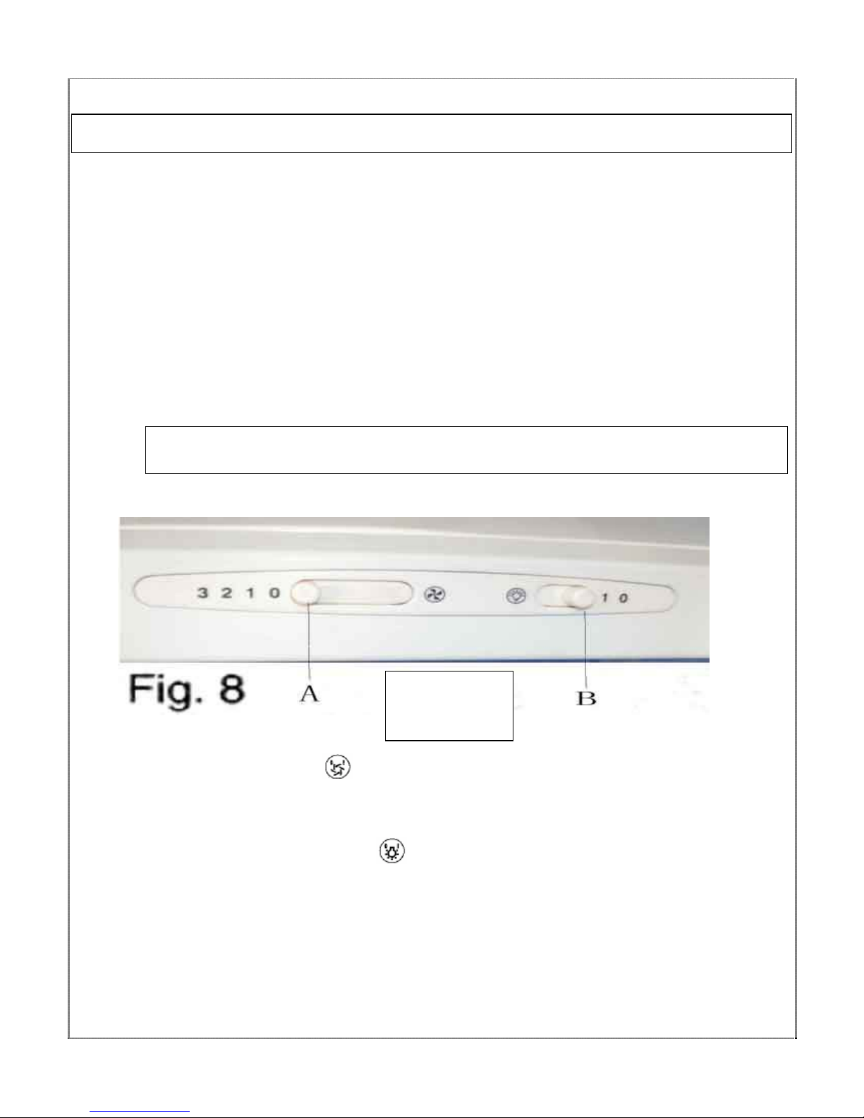
2) Find the CONTROL PANEL. It is located on the hood’s front
surface near the upper right corner of the unit.
3) The CONTROL PANEL contains switches as shown in the Figure below.
These perform separate functions. You will need to understand what
both switches do before you attempt to use your cooker hood.
Note: The hood should be switched on at least as soon as you start
cooking.
*Slider switch:
MOTOR ON /OFF switch – the ‘
’ switch (‘A’ in figure above) turns the motor
on and off and adjusts its speed. There are three speeds, pushing the switch to
the right increases the speeds.
LIGHT ON/OFF switch - Pressing the ‘
’ switch (‘B’ in figure above) turns your
cooker hood’s light on and off.
Using your Cooker Hood:
Your Cooker
Hood’s
Control Panel
Page 8
7
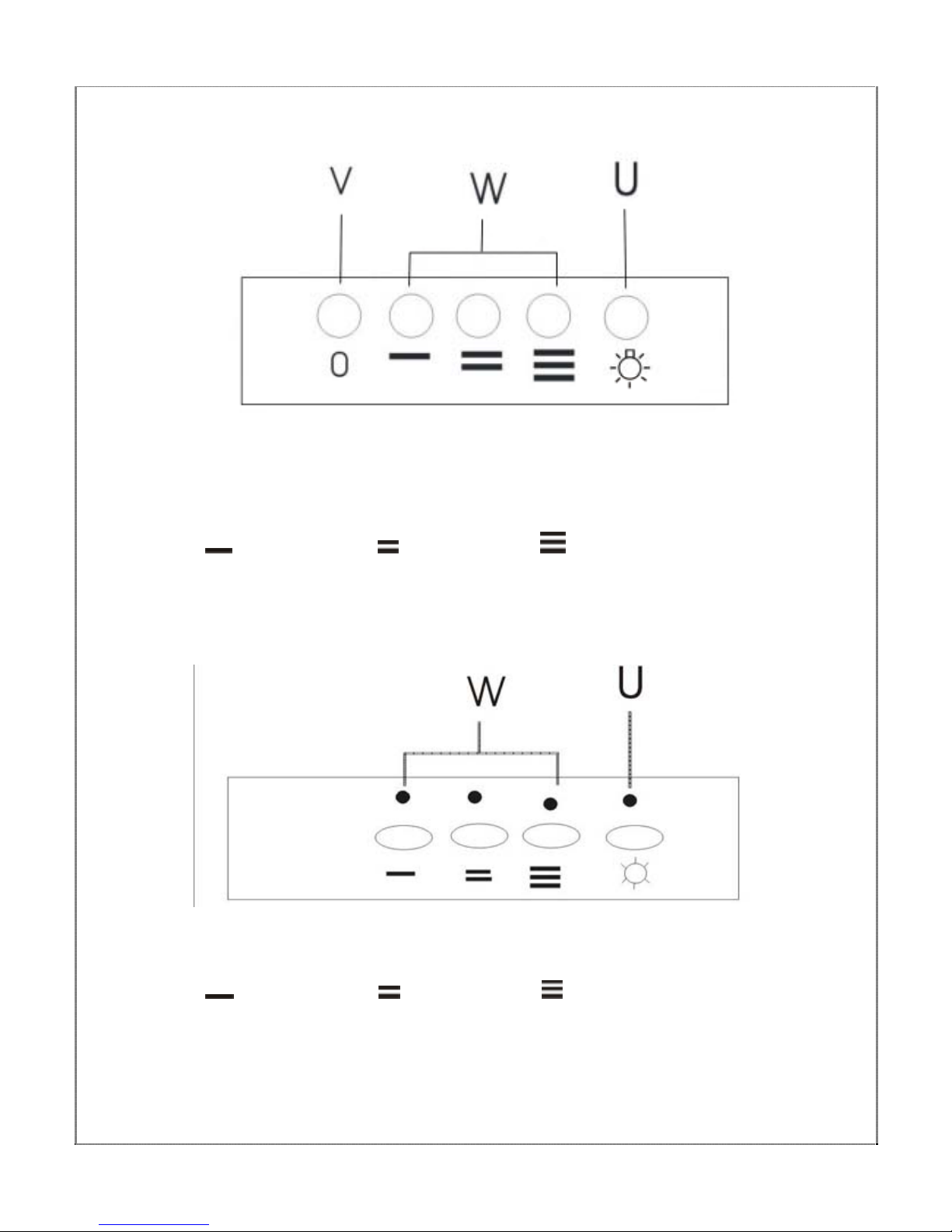
*Push button :
KEY
‘V’- Motor Off button
‘W’ - Motor operation:
= low speed, = mid speed, = high speed.
‘U’ - Light ‘ON/OFF’ button-This button controls the light
*Electronic button
KEY
‘W’ - Motor operation:
= low speed, = mid speed, = high speed.
‘U’ – Light ‘on/off’ button-This button controls the light
Page 9
8
PLEASE NOTE THAT YOUR COOKER HOOD CAN BE USED EITHER
IN RECIRCULATION MODE OR IN EXTRACTION MODE. TO USE
IN RE-CIRCULATION MODE, YOU WILL NEED TO FIT THE
CARBON FOAM.
* IMPORTANT:
Before cleaning, always ensure that you
have switched your cooker hood OFF at the omni-polar
switch, set at the wall from the cable:
Cleaning
 Clean the external parts with
mild liquid detergents on a
damp cloth.
 Never use abrasive powder,
corrosive solvents or brushes.
 Never insert pointed objects
into the motor’s protective grid.
 Only clean the control panel
and filter grill with a damp
cloth and delicate detergents.
 Be sure to replace the
carbon filters at the
recommended intervals.
Build up could cause a
fire hazard.
 Never take out the
grease filters and
attempt to clean the
space above where they
are set.
________________________________________________
Anti-Grease Grill
 Your cooker hood includes an anti-grease grill
which helps absorb vapour-suspended grease
particles to protect your kitchen & furniture from
greasy residues.
 The metal grill may become inflammable if it
becomes saturated with greasy residue.
Cleaning your Cooker Hood:
Page 10
9
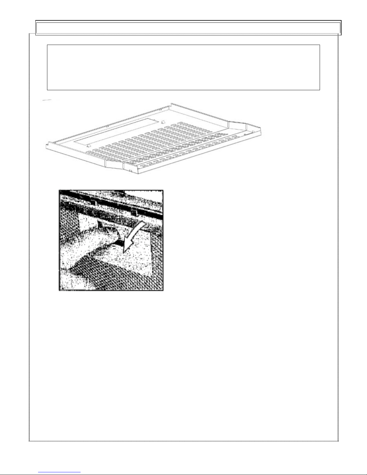
9 To prevent this fire hazard, the grill should be
cleaned regularly (depending on use) every 10-15
days and at least every three months in a dishwasher
or in hot water with normal washing-up detergent.
First remove the antigrease filter by sliding the
securing nibs at the sides
of the grille on the
underside of the hood.
You can now clean
the anti-grease grill:
To clean the grill by hand:
9 Soak it for about one hour in
hot water with a greaseloosening detergent then rinse off
thoroughly with hot water.
9 Repeat the process if needed.
Refit the grease grill once it has
dried.
Maintenance - Cleaning the Anti-grease Filters
Page 11
10
• NOTE - After carefully rinsing and drying the anti-
grease grill, put it back in place. Never put it back
in wet!
• Never attempt to use your Cooker hood without the
grease filter grill in place!
a) Changing the light bulb
9 Before changing the light bulb, ensure that the appliance is not
live (i.e., ensure that you have switched it off at the omni-polar switch on
the wall switch plate.).
9 Open the grease filter support grill (see previous page).
9 Find the bulb in its position.
9 Change the bulb
using only olive-shaped spares.
* PLEASE NOTE - Defective bulbs should be replaced
immediately.
9 Replace the grease filter support grill.
Maintenance – Changing the Light Bulb and Carbon Foam
Page 12
11
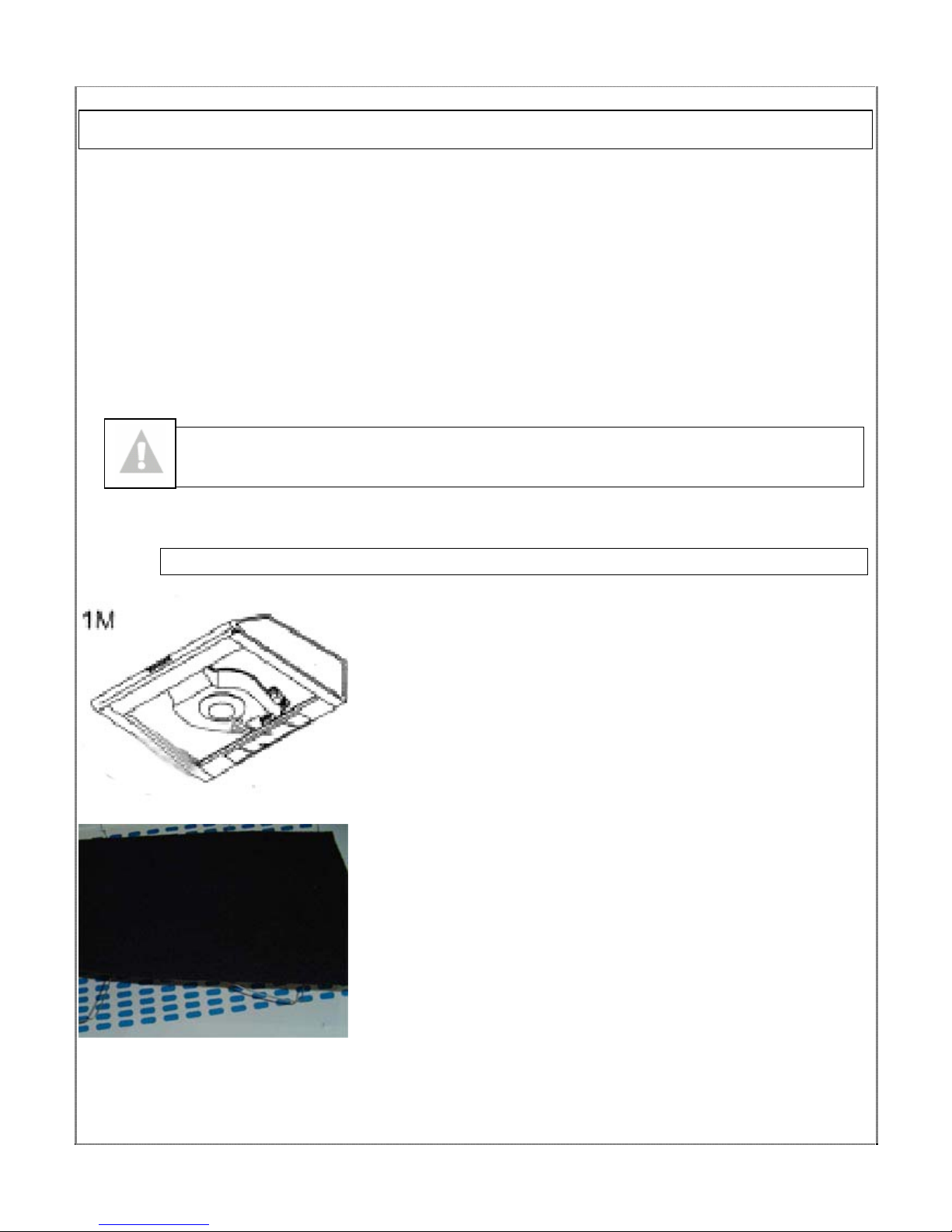
Your Cooker Hood uses a CARBON and GREASE Filter to
purify the air for the air recirculation function.
You will find that one filter will attach over the front of the
fan motor (please see figure at bottom of page).
The active carbon filter must be replaced regularly, at least once
every three months, to allow normal operation.
BBeeffoorree ssttaarrttiinngg ttoo ffiitt tthhee ffiilltteerr,, ttuurrnn tthhee oommnnii--ppoollaarr
sswwiittcchh ((wwhheerree ccaabbllee mmeeeettss wwaallll ppllaattee)) OOFFFF..
To change the Carbon and Grease Filter
1) Remove the metal grease filter grill
(see page 9).
2) Take carbon foam above the grease
filter .
3) Put the small steel wire press the
carbon foam, please make sure press
tidy and not removable.
.
4) Replace the anti-grease filter
grill.
Installing / Changing the Carbon Filter
Page 13
12
Installing / Changing the
Carbon Filter.
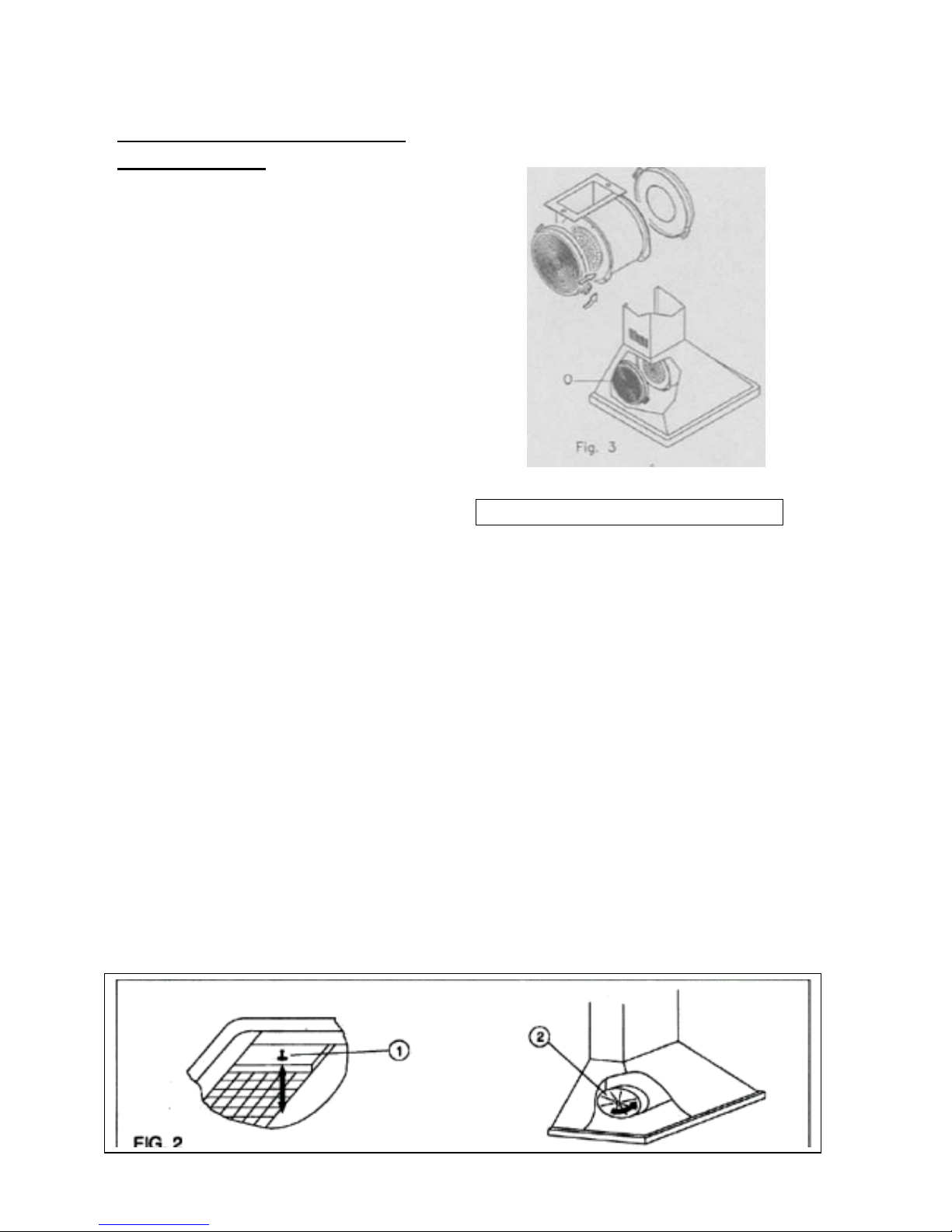
Your Cooker Hood uses a
pair of CARBON FILTERS to
purify the air for the air
recirculation function.
You will find that the filters
will attach to both sides of
the fan motor (please see
figures at bottom of page).
The active carbon filters must
be replaced regularly, at least
once every three months,
to allow normal operation.
Before starting to fit the carbon
filter, turn the omni-polar
switch off at the wall.
CHANGING THE CARBON FILTER
1)Press the handle of the metal grease
filter towards the rear part of the unit
until it is released from the front housing,
and remove it by pressing downwards (Fig.
2 - above).
2)Remove the old carbon filters by
twisting them anticlockwise until they
unlatch from the sides of the motor.
3)Place the new carbon filters (which
have two fixing tongues), turning
clockwise so that the tongues latch onto
the motor’s sides. (Fig. 3 - left).
4) Reposition the anti-grease metallic
filter grills.
Page 14
13
Before installation and usage, read all the instructions and make sure that the
voltage (V) and the frequency (Hz) indicated on the identification plate (found
inside your Cooker Hood) and all the data inside the appliance are exactly the
same as the voltage and frequency in your home.
NOTE: The manufacturer declines all responsibility in the event of failure to observe all the
accident-prevention regulations in force which are necessary for normal use and regular
operation of the electric system.
______________________________________________
ELECTRICAL CONNECTION
YYoouurr ccooookkeerr hhoooodd iiss iinntteennddeedd ffoorr ffiitttteedd aanndd ppeerrmmaanneenntt iinnssttaallllaattiioonn..
o The power cable must be
connected to the terminals
marked L (live) and N (neutral)
in the hood and fixed with a
cable clamp.
o The cooker hood’s power cable
must be fitted upstream from the
electrical connection using an
omni-polar switch with a contact
distance of at least 3mm.
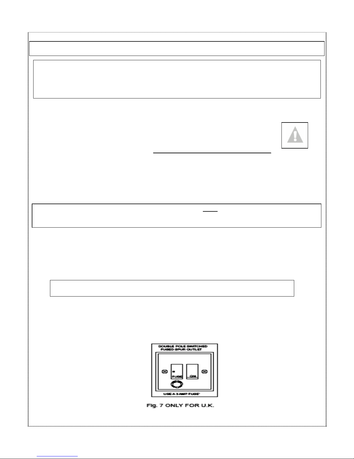
NOTE: (UK only) WARNING – THIS APPLIANCE MUST NOT
BE EARTHED. It should only be
connected by a competent person using fixed wiring via a DOUBLE POLE SWITCHED FUSED
SPUR OUTLET.
We recommend that the appliance is connected by a qualified electrician who is a member
of the N.I.C.E.I.C. and who will comply with the I.E.E. and local regulations. The wires in
the mains lead are coloured in accordance with the following U.K. code:
Blue= Neutral, Brown = Live, Green/Yellow = Ground
If you can only find two wires in the cable (blue and brown), neither must be
connected to the Earth terminal!
• As the colours of the wires in the appliance’s mains lead may not
correspond with the coloured markings identifying the terminals in
your spur box, please proceed as follows:
__________________________________________________________
1) The BLUE WIRE
must be connected
to the terminal
marked ‘N’
(Neutral), or
coloured Black.
2)
The BROWN
WIRE must be
connected to the
terminal marked
‘L’ (‘Live’), or
coloured RED
(Fig. 7 – at left
)
INSTALLATION INSTRUCTIONS - Electrical
Page 15
14
:
With the hood installed
above a hob, there should
always be a pot or pan on
the hob zone or ring that is
in use.
:
We recommend that at least
two people install this hood.
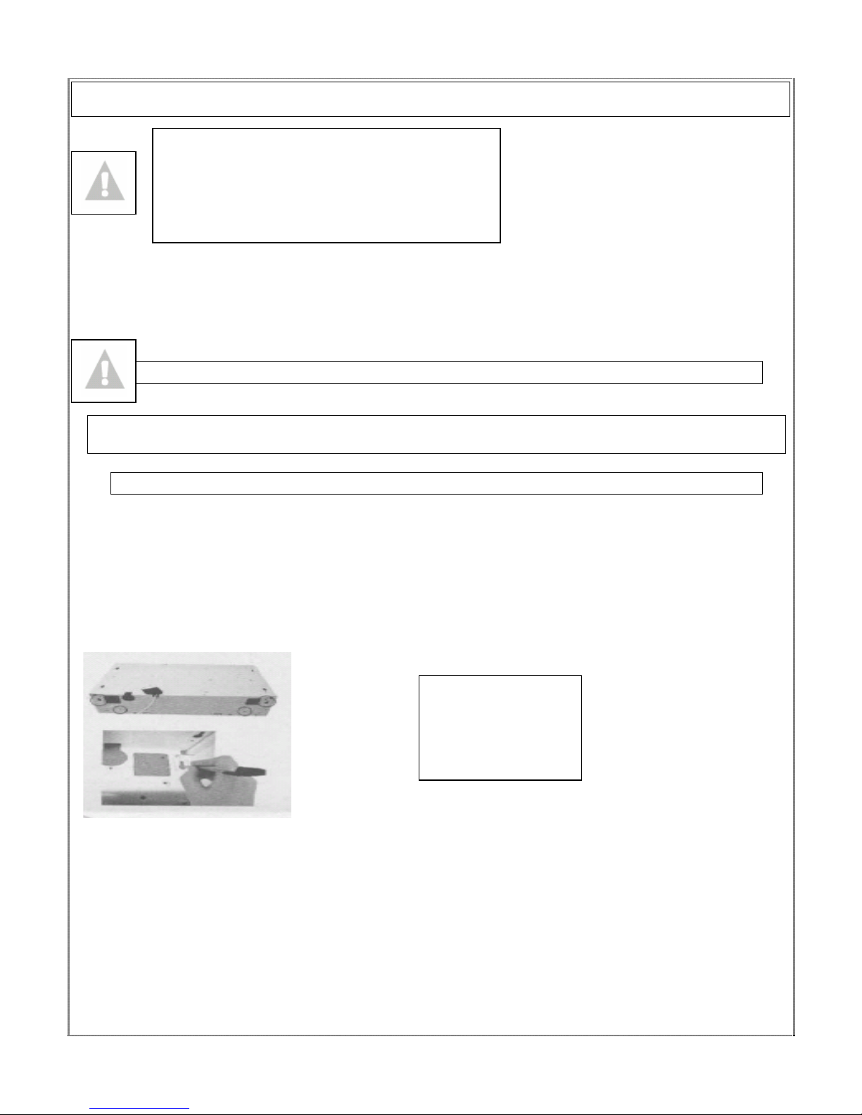
Your Cooker Hood should only be fitted on a wall on the underside of a cabinet
unit.
Do NOT position it any less than 750 mm (75 cm) above the hob.
Before Installing, Remove the metal anti-grease filter (see page 9).
NOTE: Y
OU HAVE THE CHOICE OF FITTING YOUR COOKER HOOD TO A DUCTING HOLE THAT WILL
EITHER GO ABOVE YOUR COOKER HOOD OR BEHIND IT.
(E)
WALL INSTALLATION
1) Position the hood against the wall and mark the positions for the
supporting bracket bolt holes (see Fig. 4 below) of the exhaust hole (this
hole must be 130mm in diameter).
2) Drill these holes into the wall using a 6 mm diameter drill bit. If you
intend to use your Cooker Hood as an extraction fan, you will need to fit
a ducting kit through this that will connect to your appliance.
3) Insert the raw plugs into the holes and then insert the top screws
part way, so that the screws stick out by 10mm.
4) Hang the hood up on the screws. Insert the bottom screws.
5) Tighten the screws the rest of the way in.
6) (E) For the extraction function, connect the exhaust outlet pipe to
the collar strip. Find the screw holes in the top and rear of the
cooker hood. Tighten the bolts from inside the hood.
INSTALLATION INSTRUCTIONS – installing your Cooker Hood
PLEASE NOTE THAT YOU WILL HAVE TO
DECIDE BEFORE INSTALLING YOUR
COOKER HOOD WHETHER YOU WANT IT
AS AN EXTRACTION FAN! THE
INSTRUCTIONS FOR EXTRACTION FAN
MODE WILL BE MARKED ‘(E)’ BELOW
ALL SCREWS,
RAW PLUGS,
ETC. COME
WITH YOUR
COOKER HOOD!
Page 16
15
7)
KITCHEN UNIT / UNDERSIDE OF CABINET INSTALLATION
NOTE: Ensure that the grease filter grill has been removed.
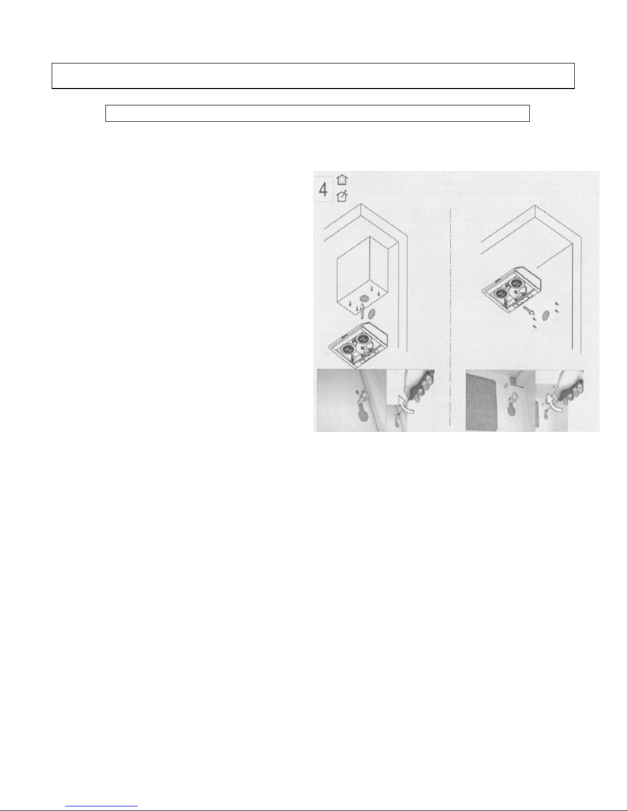
1) (E) – Extraction Function only If you
are using the top exhaust outlet
(meaning that you have plugged the
rear one), first cut a hole measuring
130mm in diameter in the floor of the
cupboard into which the hood will be
set (see Fig. 2, bottom centre of page)
so that the collar strip can be fastened.
2) If necessary, make a hole for the power
cable to feed th
rou
gh.
3) Hold the hood against the underside of
the hood and mark the points for the
supporting and fast
ening
holes.
4) Screw in the four screws supplied with
the installation
acce
ssory kit.
5) Hook the hood onto the supporting
screws and tighten them completely
(Fig. 4 – on right). Alternatively, use
the attachment holes near the previous
ones.
__________________________
6) Close the grease filter grill.
:
We recommend that at least
two people install this hood.
NOTE: Your Cooker Hood should only be fitted on a wall. Do
NOT position it any less than 750 mm (75 cm) above the hob.
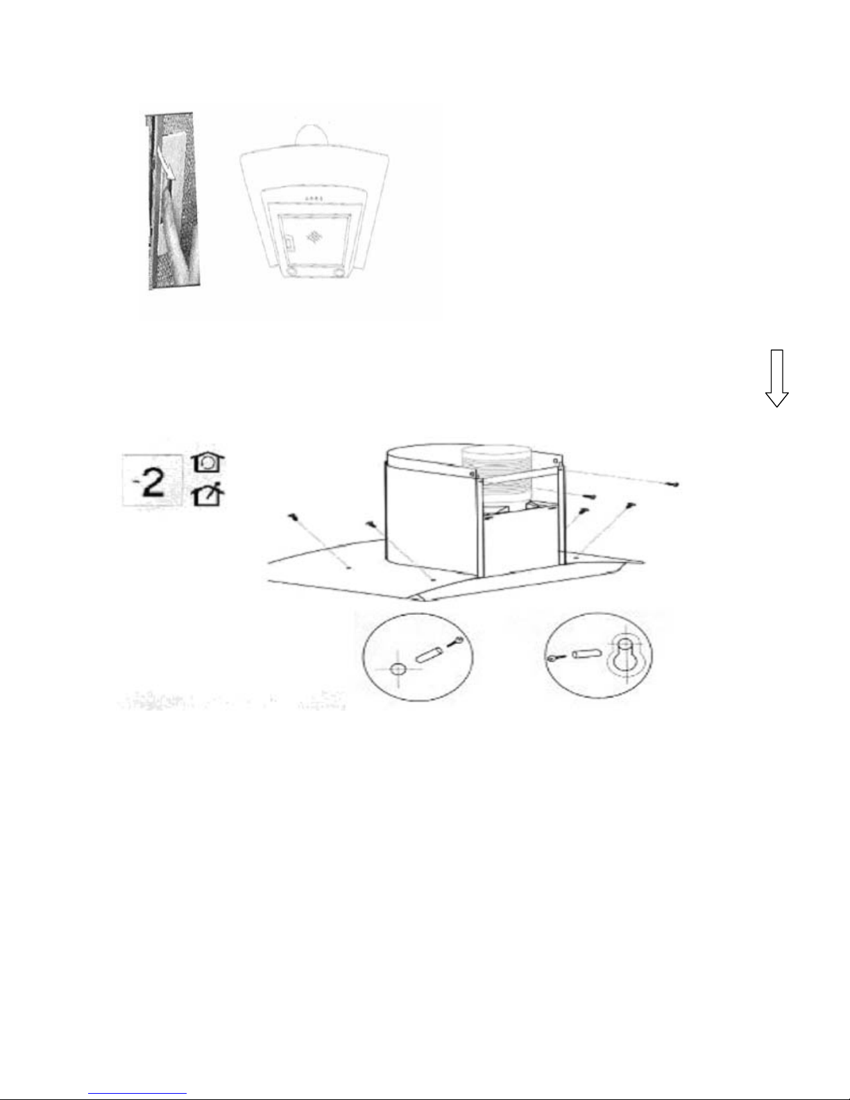
7) Remove the metal anti-grease filters
(See figure at right).
INSTALLATION INSTRUCTIONS – installing your Cooker Hood
Page 17
16
8) Position the hood against the wall and mark the position of the support
holes that are to be drilled as shown in the figure below. These support
holes can be found on Fig. 4 on next page marked as ‘D’ with the anchoring
holes marked as ‘E’ (Fig. 4 on next page). If you hood comes with an
attached jig, use that as a guide to make the marks for the screw holes.
Page 18
17
--------------------------------------------------------------------------
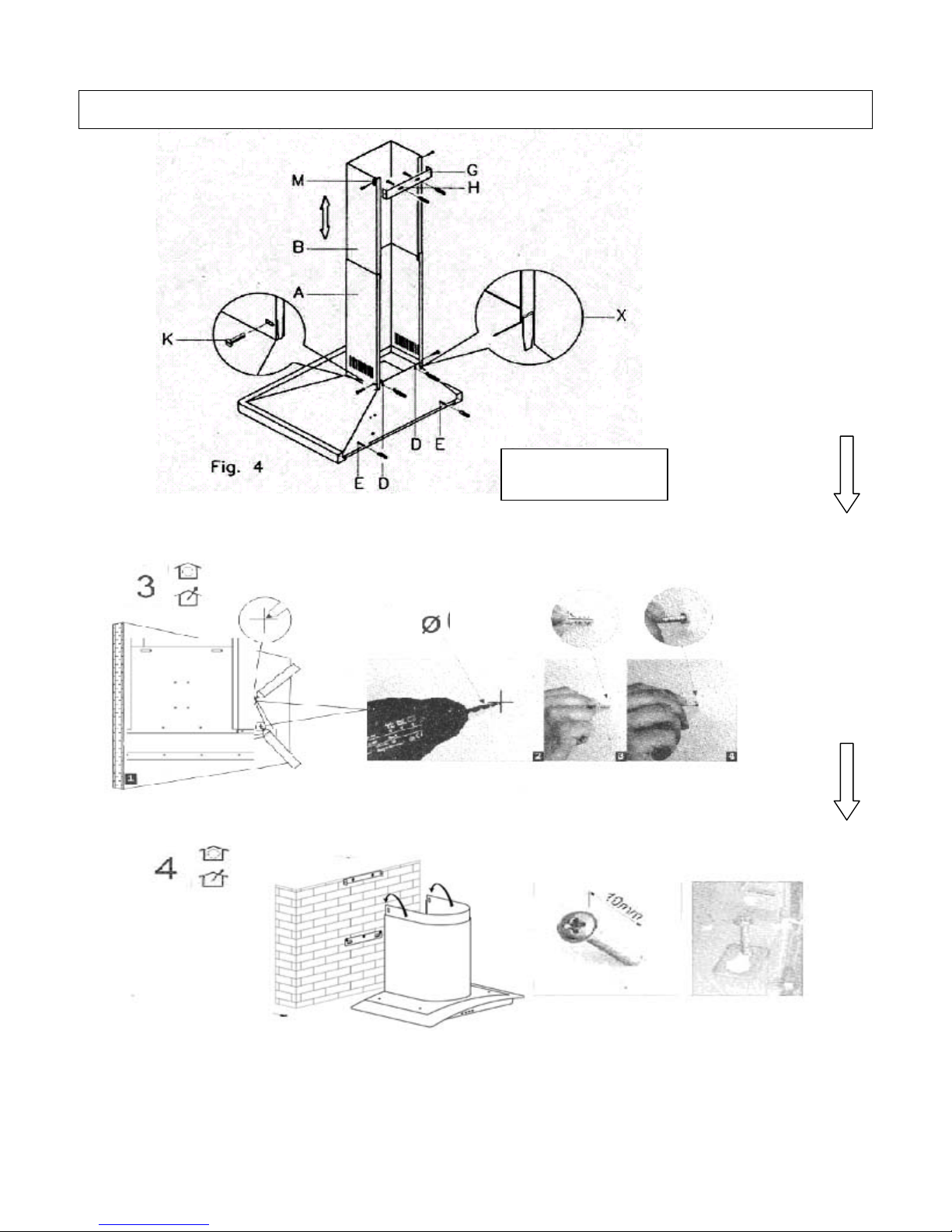
1) Using a drill bit with a 8 mm diameter, make holes in the wall where you have
marked these positions (see below).
--------------------------------------------------------------------------------------------------------------------------------------------------------------------------------------------------------------------------------------------------
2) Insert the expansion fixings (raw plugs) in the holes and then screw the
support screws halfway in (see below figure, at right).
3) Hook the hood onto the screws (see above figure) and fasten it onto the
wall, tightening the sup
port and anch
oring screws the rest of the way in (next
page, at top.)
Rear view of your
cooker hood.
INSTALLATION INSTRUCTIONS – Attachin
g
the Hood
8
Page 19
18
-------------------------------------------------------------------------------------------
-------------------------------------------------------------------------------------------
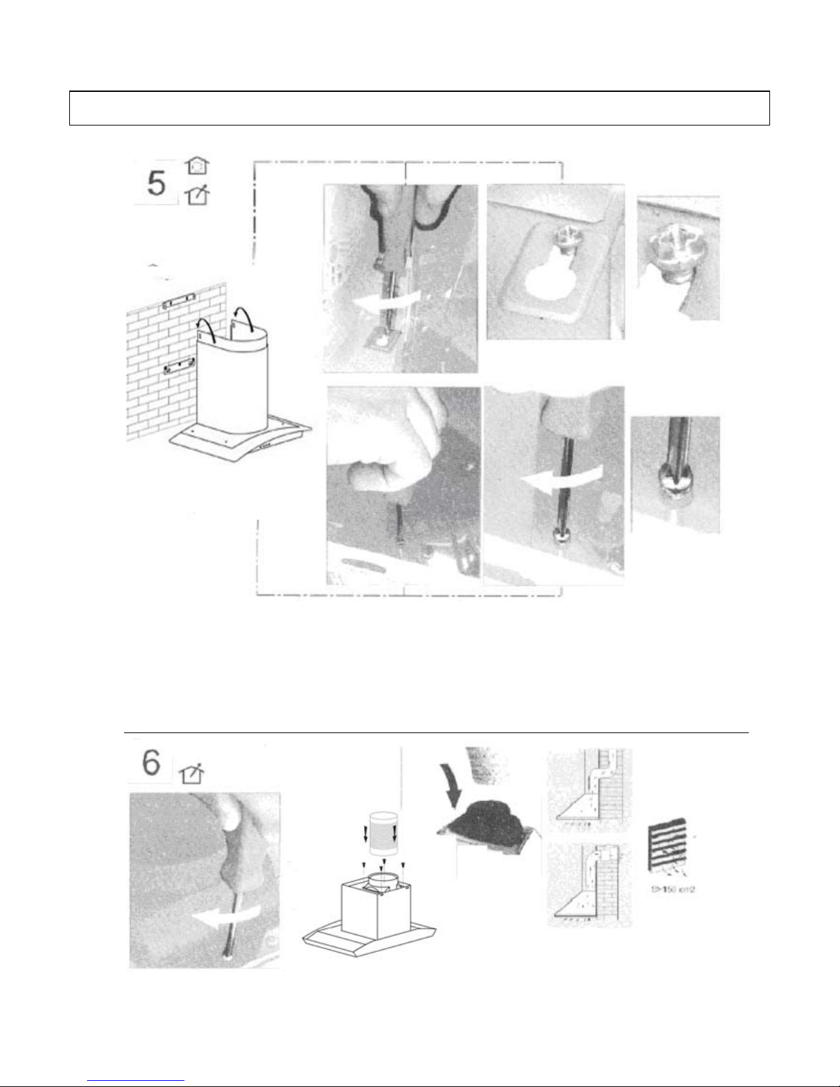
4) (EXTRACTION FUNCTION ONLY) Connect the coupling to the top of the
cooker ho
od (see below). Then connect
the discharge pipe to the coupling as
shown below. Remember that your ducting will have to match the
specifications shown in the notes on Extraction / Air Purifier (Recirculation)
Modes on p.18.
INSTALLATION INSTRUCTIONS – Attaching the Hood
Page 20
19
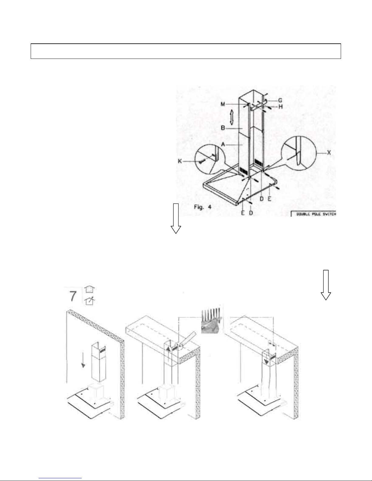
FITTING THE PIPE – Once your Cooker Hood has
been installed, you can now fit the pipe.
1) Take the two casings ‘A’ and ‘B’:
2) Rest the bottom of the casing ‘A’
on the top of the hood, taking
care to position the tabs of the
casing correctly on the back of
the hood as shown as part ‘X’ in
Figure 4 at right.
3) Fix casing ‘A’ onto the hood
using the two screws ‘K’
supplied in the bag of
accessories (Figure 4 – at right).
4) Lift the mobile part ‘B’ until it reaches the ceiling, checking
that it is perpendicular to the hood.
5) Mark the side measurement of the mobile casing ‘B’ and then
lower it (see below).
INSTALLATION INSTRUCTIONS – Fittin
g
the Chimne
y
Page 21
20
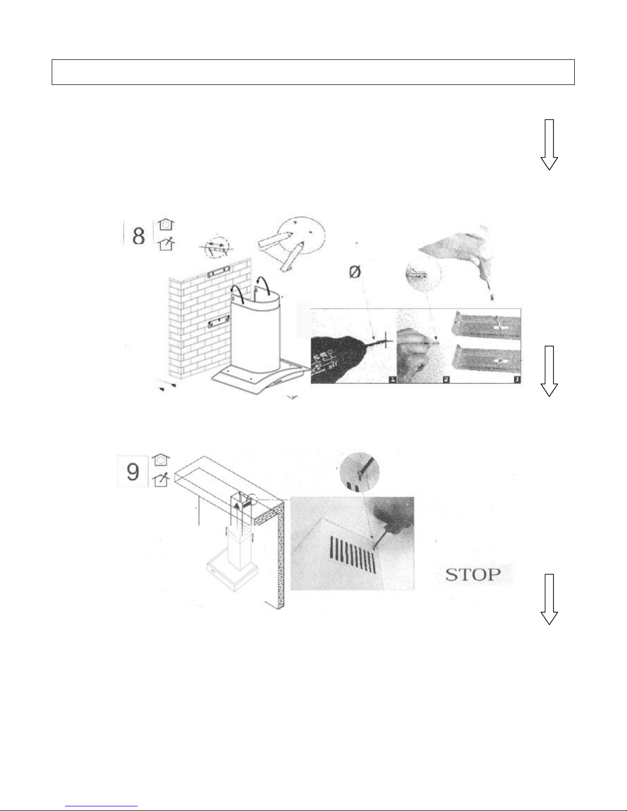
6) Take the fixing bracket ‘G’ (Fig. 4 – previous page), centre it
with respect to the mark you previously made, keeping it in
contact with the ceiling, and then mark the anchoring holes
(‘H’).
7) Using a drill bit with a 8mm diameter, make two holes on the
fixing marks you previously made (see below).
8) Insert the expansion fixings (raw plugs) provided, put bracket
‘G’ (see Fig. 4 on previous page) in position and secure it with the
screws provided.
9) Lift casing ‘B’ up to the ceiling and secure it to the bracket ‘G’,
inserting the screws provided in the holes ‘M’ (Fig. 4 – previous
page).
INSTALLATION INSTRUCTIONS – Fitting the Chimney
8
Page 22
21
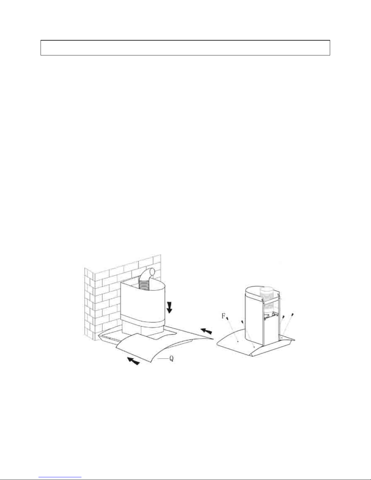
Remove the metal grease filters from the hood
Slacken both anchoring screws “F”
Place the glass ‘Q’ on the upper shelf of the hood, pushing it in
towards the wall.
Tightening the screws ‘F’ again in the hole and connecting them to
the unit.
Take care that the anchoring corner is firmly fastened, tightening it
well.
Re-insert the ventilation tube with the coupling tube ‘N’.
PLEASE NOTE * DO NOT OVERTIGHTEN THESE SCREWS OR YOU
MAY DAMAGE / DISTORT THE UNIT.
ATTACHING THE GLASS
Page 23
22
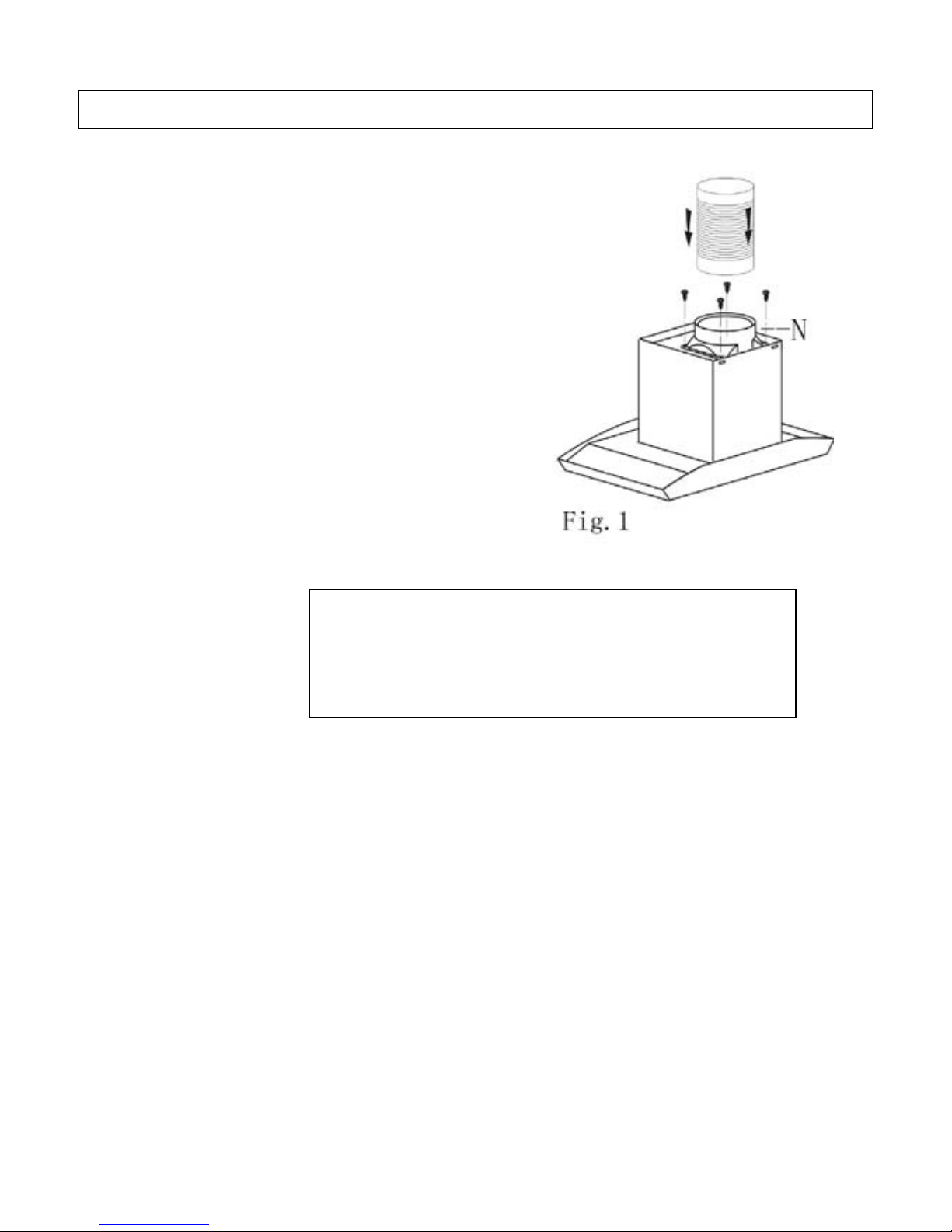
EXTRACTION OPERATION – Installation Instructions
 Ensure that you have fitted the
union (‘N’) to the upper part of the
hood using the packaged two
screws supplied inside the packing
(Fig. 1 – on right). Using a 125 mm
diameter pipe, connect the union (N)
on the upper part of the hood (see
Fig. 1) to the discharge outlet for
cooking vapours with a crosssection of at least 150 cm
².
 PLEASE NOTE: If there is no
discharge outlet and the hood is to
be fitted to an outside wall of the
building, make a hole in the wall
that is large enough to fit a wind
and rain-proof shutter with a cross
section of at least 150 cm
² and
connect this to the outlet union of
the unit by means of a pipe.
_______________________________________________ _________________________________________________________________ ________________________________________________________________________ __________________________________
.
AIR PURIFIER (RECIRCULATION) OPERATION - Installation
Instructions
The cooker hood can be
converted to work as an air
purifier in the event that there is
no provision for an external air
discharge duct.
In this case, air is recycled through
the vent ‘R’ (Fig. 1 – above). When
using the unit as an air purifier, you
need to install two active carbon
filters to absorb cooking vapours
(please see page 11).
Extraction / Air Purifier Modes of Operation
Please note: For the extraction function, you
will need to connect a 125 mm diameter
outlet chimney to the spigot ‘N’ in fig. 1
above. This pipe is not provided with your
cooker hood. See fi
g
ure on left.
Page 24
23
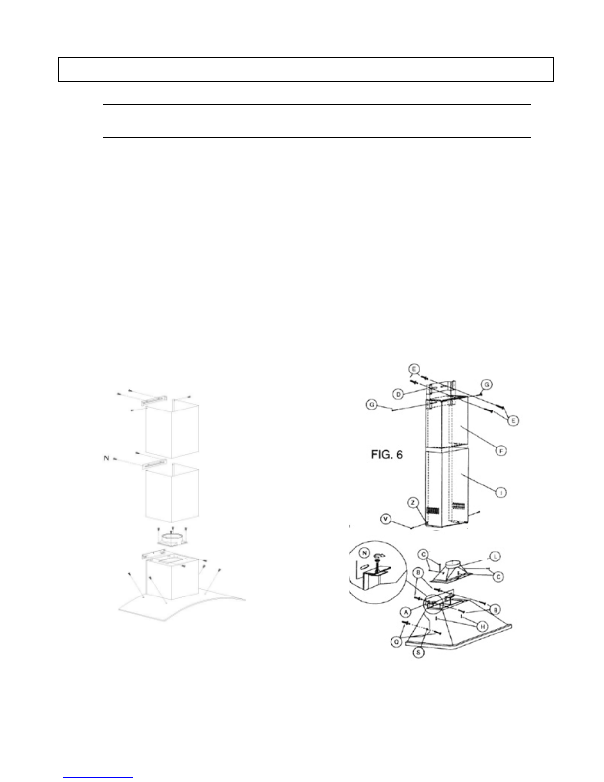
* Note on what to do if your Cooker Hood is the version that
comes with a BRACKET.
Please note that your cooker hood may include a lower bracket. If
this is the case, you will need to have it installed as such.
This will mean a slight change in how the cooker hood is to be
installed from the process shown on page 13.
In Fig. 6, below, you will see an exploded view of your cooker hood
and (inset), the bracketed connecting area of the hood (‘N’).
Hook or attach the hood to the bracket using the
screws supplied and carefully check that it has
been done properly. A few hoods may be
supplied with specific screws for vertical or
horizontal adjustment.
Fig 6:
If your Cooker Hood comes with a Lower Bracket
Page 25
24
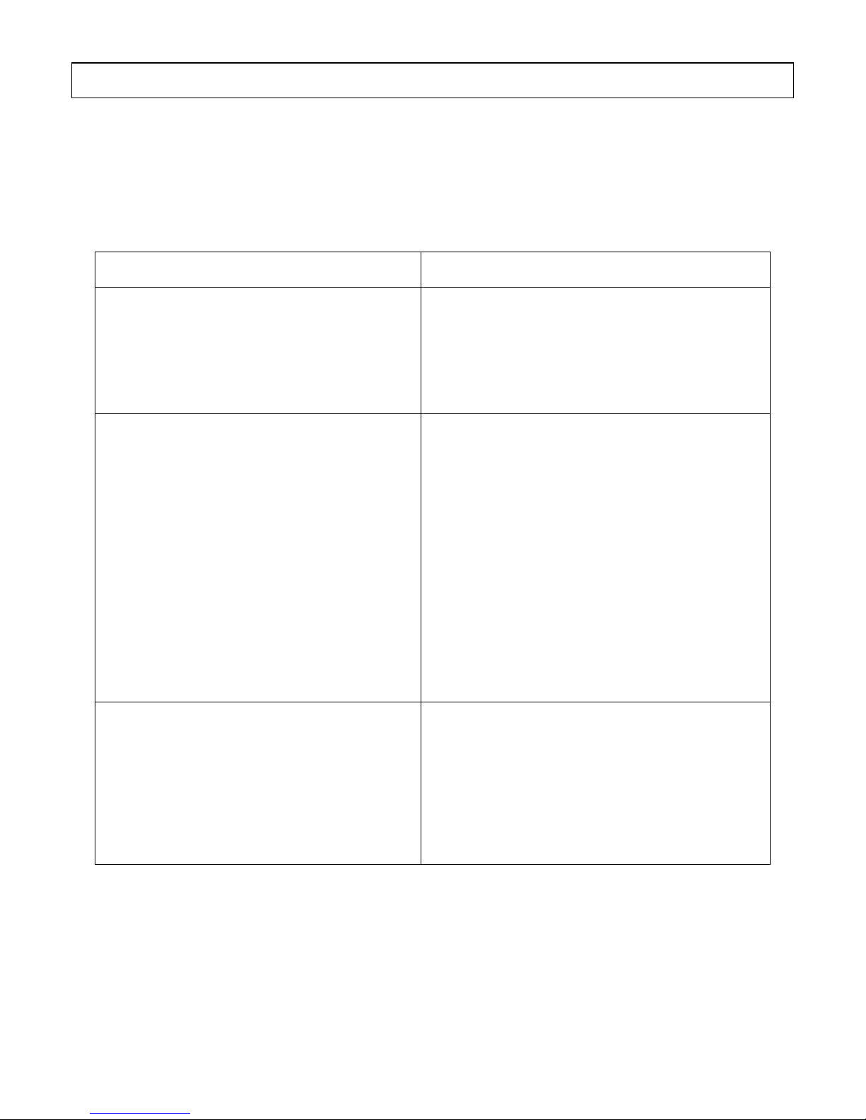
If something has gone wrong with your Cooker Hood, checking
against this chart might keep you from having to call for service.
Symptom Solution
The cooker hood will not start!
• Check that the hood is connected
to the electricity supply.
• Check that the fan speed control is
set properly.
The cooker hood is not working
effectively!
• The fan speed is not set high enough.
• The grease filter is dirty.
• The kitchen is not ventilated well
enough.
• If the hood is set for recirculation,
check that the carbon filters have not
expired.
• If the hood is set for extraction, check
that the ducting and outlets are not
blocked.
The cooker hood has switched off
during operation!
• The safety cut-out device has been
tripped.
• Turn off the hob and then wait for the
device to reset.
• Note that if you have installed your
cooker hood too low, this will happen.
If it happens frequently, it will be
damaged.
Troubleshooting
Page 26
THIS WARRANTY IS VALID IN NEW ZEALAND ONLY
Note:
Please complete the following details when you
unpack the product and return the bottom portion of
this card to:
Applico Ltd
Private Bag 92-900
Onehunga
Auckland, New Zealand
Warranty:
These products are covered by a warranty for a
period of 24 months from the date of purchase,
subject to the following conditions*. The Warranty
covers rectification free of charge of any fault arising
from defective materials or components, or faulty
workmanship or assembly.
* The conditions above mentioned are:
1. that the purchaser carefully follows all instructions
packed with the product;
2. that the purchaser carefully follows the installation
instructions provided and complies with electrical
wiring regulations, gas and or plumbing codes;
3. that the purchaser carefully follows instructions
provided in the owner’s handbook relating to the
proper use and care of the product and does not
use the product for any purpose other than the
domestic use for which it has been designed;
4. all appliances being used in a non residential
commercial situation are covered by a 3 month
warranty from the original date of purchase;
5. that the product was purchased and installed in
New Zealand;
6. that this warranty does not extend to:
a) optional glass lids for hobs apart from claims
which relate to mechanical or physical damage
thereof at the date of purchase;
b) light bulbs
c) damage to ceramic glass caused by liquid
or solid spillovers, lack of maintenance, or
impact;
d) damage to surface coatings caused by
cleaning or maintenance using products not
recommended by the owner’s handbook;
e) defects caused by normal wear and tear,
accident, negligence, alteration, misuse or
incorrect installations;
f) a product dismantled, repaired or serviced
by any serviceman other than an authorised
service agent;
g) a product not in possession of the original
purchaser;
7. that if the product is a microwave or small
appliance it must be returned to the dealer for
servicing. These products, unless stated otherwise
have a 12 month warranty from original date
of purchase with 24 months on the microwave
magnetron; Waste disposers have a 24 month
warranty;
8. The provision of service under this Warranty is
limited by a 25km boundary from the retailer
where the product was purchased. Such travelling
outside of these limits will incur commercial cost
to be paid by you, regulated by the number of
kilometres travelled beyond the 25km limit (50km
return trip).
Nothing herein contained shall be construed in any
way as excluding or limiting your rights under the
Consumer Guarantees Acts 1993.
For service please contact the dealer/retailer from
whom you purchased the product. If you are unable
to establish the date of purchase, or the fault is not
covered by this Warranty, or if the product is found to
be in working order, you will be required to bear all
service call charges.
Note: Completion of this Warranty Registration
Card constitutes acceptance of the terms and
conditions of this Warranty.
Distributed by Applico Ltd
www.applico.co.nz
Please complete this section, detach and post to:
Applico Warranty, Private Bag 92-900, Onehunga, Auckland
or register online at www.applico.co.nz
PRODUCT TYPE: ................................................. MODEL NO:...................................................................
SERIAL NO: .......................................................... DATE OF PURCHASE: ................................................
RETAILER: ............................................................ INVOICE/SALES DOCKET NO: ................................
RETAILER ADDRESS: ...........................................................................................................................
PURCHASERS’ NAME: ......................................................................................................................
ADDRESS:........................................................................................................................................
PROCLAIM APL.AD.120
WARRANTY REGISTRATION CARD
applico_warranty_card.indd 1applico_warranty_card.indd 1 19/10/06 4:17:46 PM19/10/06 4:17:46 PM
Page 27
Applico Ltd
Warranty Department
Private Bag 92-900
Onehunga
Auckland
Affix
stamp
here
applico_warranty_card.indd 2applico_warranty_card.indd 2 19/10/06 4:17:46 PM19/10/06 4:17:46 PM
 Loading...