

Classic Organ Works CMK-2 User Manual
Dmbttjd!Pshbo!Xpslt!
CMK-2
Classic MIDI Keyboard
User Manual
Version 1.5
Div. of:
ARTISAN CLASSIC ORGAN INC.


MIDI KEYBOARD CMK-2 CONTENTS MANUAL v1.5
CLASSIC MIDI KEYBOARD
CMK-2
TABLE OF CONTENTS
MIDI Volume 21
MIDI Expression 21
1. LIMITED WARRANTY ....................5
Programming Keyboard Functions ...... 22
Table 9: Programming Functions ........................22
2. INTRODUCTION .............................7
Description............................................... 7
Package Contents.................................... 8
Table 1: Package Contents 8
Figure 1: CMK-2 components: 8
Figure 2: CMK-2 connections 9
3. INSTALLATION ............................11
Physical Installation .............................. 11
Figure 3: Bracket Installation 11
Figure 4: Bracket Goes above Keyboard Mount 11
Figure 5: Install three #8 Screws in the Underside 12
Connectors............................................. 12
Figure 6: Rear View Connections 12
6. SOFTWARE CONFIGURATION .. 25
Introduction ............................................ 25
Software Installation.............................. 25
Figure 11 Installing ‘CMK-2_Setup.exe’ file. 25
Figure 12 Select a directory to install the program 26
Figure 13 Adding an icon to the start menu 26
Figure 14 Creating an icon on the desktop 26
Figure 15 Confirmation window 26
Figure 16 Setup progress window 26
Figure 17 Confirms successful installation 26
Software Startup .................................... 27
Figure 18 Config software startup screen. 27
Figure 19 Config software main menu. 27
Functions of the Menus......................... 28
Power Connections ............................... 13
Figure 7: Power Terminal Block Connections 13
MIDI Connections .................................. 14
Figure 8: Connecting Cables to a Keyboard Stack 14
Connecting Swell Shoes ....................... 15
Figure 9 Wiring Schematic for Analog inputs 15
Table 2: Connection Chart.................................. 15
Software Installation (Windows and MacIntosh
users) 16
4. MIDI SPECIFICATION ..................17
Table 7: MIDI messages relevant to Hauptwerk. 19
Table 8: Default Configuration for Hauptwerk .... 19
Figure 10: 5-pin DIN connections 20
Figure 20: Toolbars in CMK-2Config software 28
1. File Menu 28
Figure 21: Software attempting to connect 29
Figure 22: MIDI Interface device choice 29
Figure 23: Software detecting keyboards 29
Figure 24: Loading configuration. 29
Figure 25: Requesting CMK Configuration 30
Figure 26: Confirmation Window. 30
2. Edit Menu 30
3. Options Menu 31
Figure 27: MIDI Input Output Setup windows 31
4. Help Menu 31
Figure 28: Help Menu 31
Configuring Multiple Keyboards........... 32
Edit a Previously-Saved CMK
Configuration .........................................33
5. HARDWARE CONFIGURATION .. 21
Introduction............................................ 21
Power-On Self Test................................ 21
Analog Input Pins .................................. 21
MIDI Crescendo – for Ahlborn Archive modules 21
Figure 29: Configuration File selection window. 33
1. Keyboard Functions, MIDI Channels 34
Figure 30: Program window 34
2. Expression Shoe Functions 36
3. General Settings 36
4. Piston Functions 37
Figure 31: Piston function drop-down menu. 37
CMK-2 Manual 1.5.doc CMK-2 MANUAL 3

MIDI KEYBOARD CMK-2 CONTENTS MANUAL v1.5
7. REFERENCES ..............................41
8. APPENDIX A: ...............................43
9. APPENDIX B: ...............................45
10. APPENDIX C: .............................53
Figure 32: CMK-2A-SS Circuit board Silk Screen 53
Figure 33: CMK-2A Circuit Board Schematic 54
Figure 34: CMK-2 Piston Rail Screen 55
Figure 35: CMK-2 Piston Rail Schematic 56
11. APPENDIX D: .............................57
Figure 36: CMK-2 Piston Rail Front Panel 58
12. APPENDIX E:.............................. 59
13. APPENDIX F: ............................. 61
MIDI Sound Sets..................................... 61
Table 19: Sound Set Groups............................... 62
Table 20: General MIDI Program Numbers ........63
Table 21: General MIDI Percussion Key Map..... 64
14. APPENDIX G:............................. 65
Mating the Brackets............................... 65
Figure 37: Small Mounting Bracket for Top Manual65
Figure 38: Large Bracket for other Manuals 65
Figure 39: Mating the Small and Large Brackets 65
Figure 40: Connecting Two Brackets 65
Figure 41: Brackets mated and closed 66
Figure 42: A Four-Manual Stack Open 66
Figure 43: A Four-Manual Stack Closed 66
Figure 44: A Completed Four-Manual Stack 66
15. DISCLAIMER.............................. 67
16. TROUBLESHOOTING................ 69
4 2009 CLASSIC ORGAN WORKS CMK-2 Manual 1.5.doc

MIDI KEYBOARD CMK-2 WARRANTY MANUAL v1.5
CLASSIC MIDI KEYBOARD
CMK-2
1. LIMITED WARRANTY
Classic Organ Works warrants the Classic MIDI
Keyboard (CMK-2) to be free from defects in
materials and workmanship under normal use for a
period of ONE YEAR from the delivery date.
This warranty applies only if the original
purchaser who has the bill of sale owns the
product.
This warranty explicitly excludes any cables
provided with the CMK-2, which may become
defective because of normal wear and tear. The
DC power adaptor is included in the warranty
however.
As soon as a defect is detected, contact Classic
Organ Works. In particular, defects due to
shipping should be reported within 5 days for
insurance claim purposes. For all other defects,
Classic Organ Works agrees to repair or replace
all defective parts of said products, which are
returned, transportation prepaid, for inspection at
its service centre within the period of the
warranty.
In the event that Classic Organ Works
determines the product requires repair because of
user misuse or regular wear, it will assess a fair
repair or replacement fee. The customer will have
the option to pay this fee and have the unit
repaired and returned, or not pay this fee and have
the unit returned un-repaired.
Classic Organ Works will not be liable for
consequential, special, indirect, or similar
damages or claims including loss of profit or any
other commercial damage, and in no event will
Classic Organ Works’ liability for any damages
to the purchaser or any other person exceed the
price paid for the product, regardless of any form
of the claim.
Classic Organ Works specifically disclaims all
other warranties, expressed or implied.
Specifically, Classic Organ Works makes no
warranty that the product is fit for any particular
purpose.
This warranty shall be interpreted, and governed
by applicable laws in the province of Ontario,
Canada. If any provision of this warranty is found
void, invalid or unenforceable, it will not affect
the validity of the balance of the warranty, which
shall remain valid and enforceable according to its
terms. In the event any remedy hereunder is
determined to have failed of its essential purpose,
all limitations of liability and exclusion of
damages set forth herein shall remain in full force
and effect.
CMK-2 Manual 1.5.doc 2009 CLASSIC ORGAN WORKS 5


MIDI KEYBOARD CMK-2 INTRODUCTION MANUAL v1.5
CLASSIC MIDI KEYBOARD
CMK-2-1
2. INTRODUCTION
Description
The CMK-2 is a MIDI keyboard controller designed for the modern organist. It combines technology and
classical church organ ideas into an innovative MIDI device.
The keyboard features:
• Tracker organ style key action
• User-programmable pistons
• A stacking mechanism for mounting multiple manuals in a traditional organ configuration
• Inputs for expression shoes
• Velocity sensitive (optional)
With the CMK-2, MIDI software and sound modules may be controlled as if they were part of the organ. The
CMK-2 is designed to work with all of your favorite hardware and software, including:
• Crumhorn Labs’ Hauptwerk virtual organ software
• Ahlborn-Galanti’s Archive MIDI sound modules
• MidiTzer virtual organ software
• Products capable of being controlled by standard MIDI messages
Enjoy your new CMK-2!
CMK-2 Manual 1.5.doc 2009 CLASSIC ORGAN WORKS 7
MIDI KEYBOARD CMK-2 INTRODUCTION MANUAL v1.5
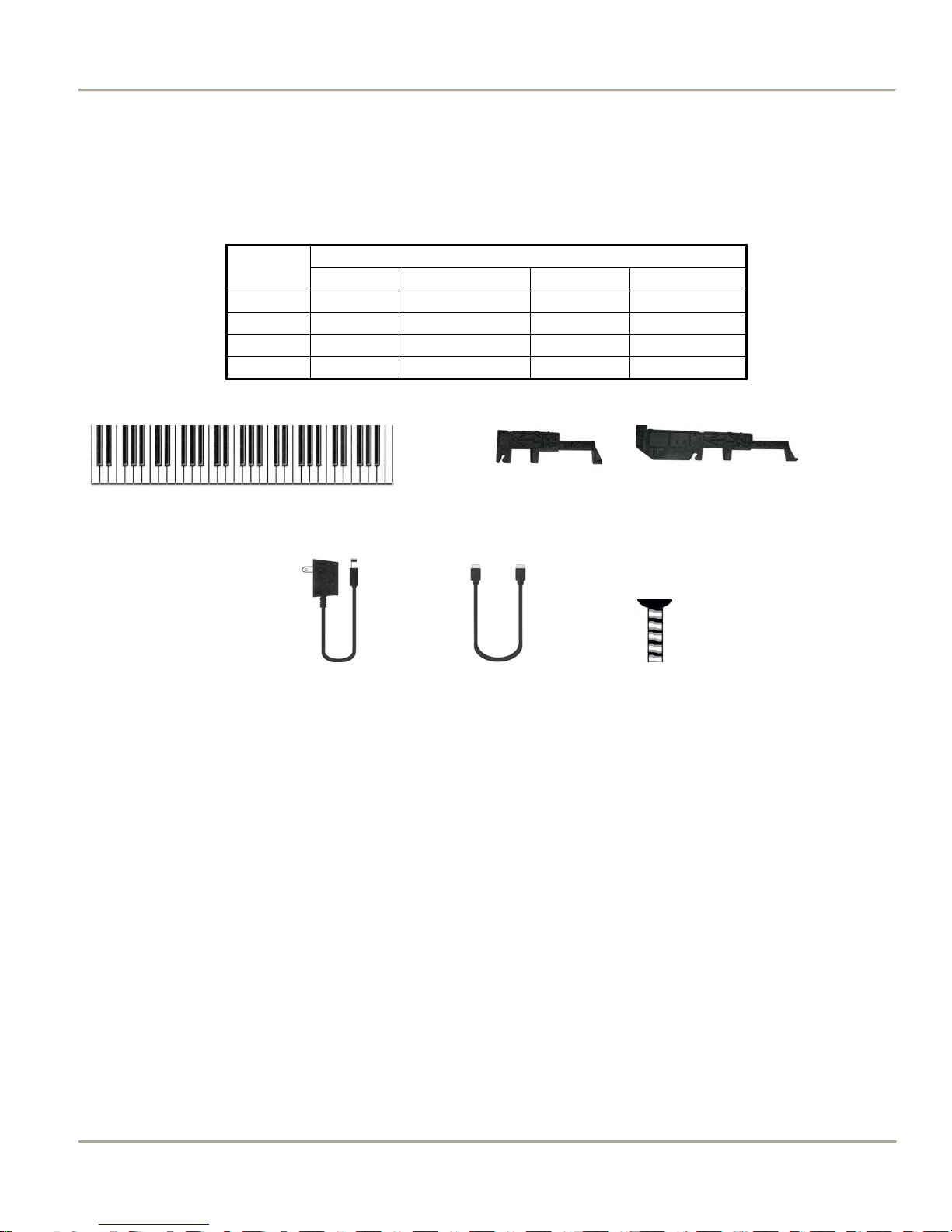
Package Contents
Table 1: Package Contents
Setup
Manual(s) Stacking Bracket DC Adapter MIDI Cable(s)
1 Manual 1 2 x B 1 1
2 Manual 2 2 x B + 2 x C 1 2
3 Manual 3 2 x B + 4 x C 1 3
4 Manual 4 2 x B + 6 x C 1 * 4
A B C
Items
D E F
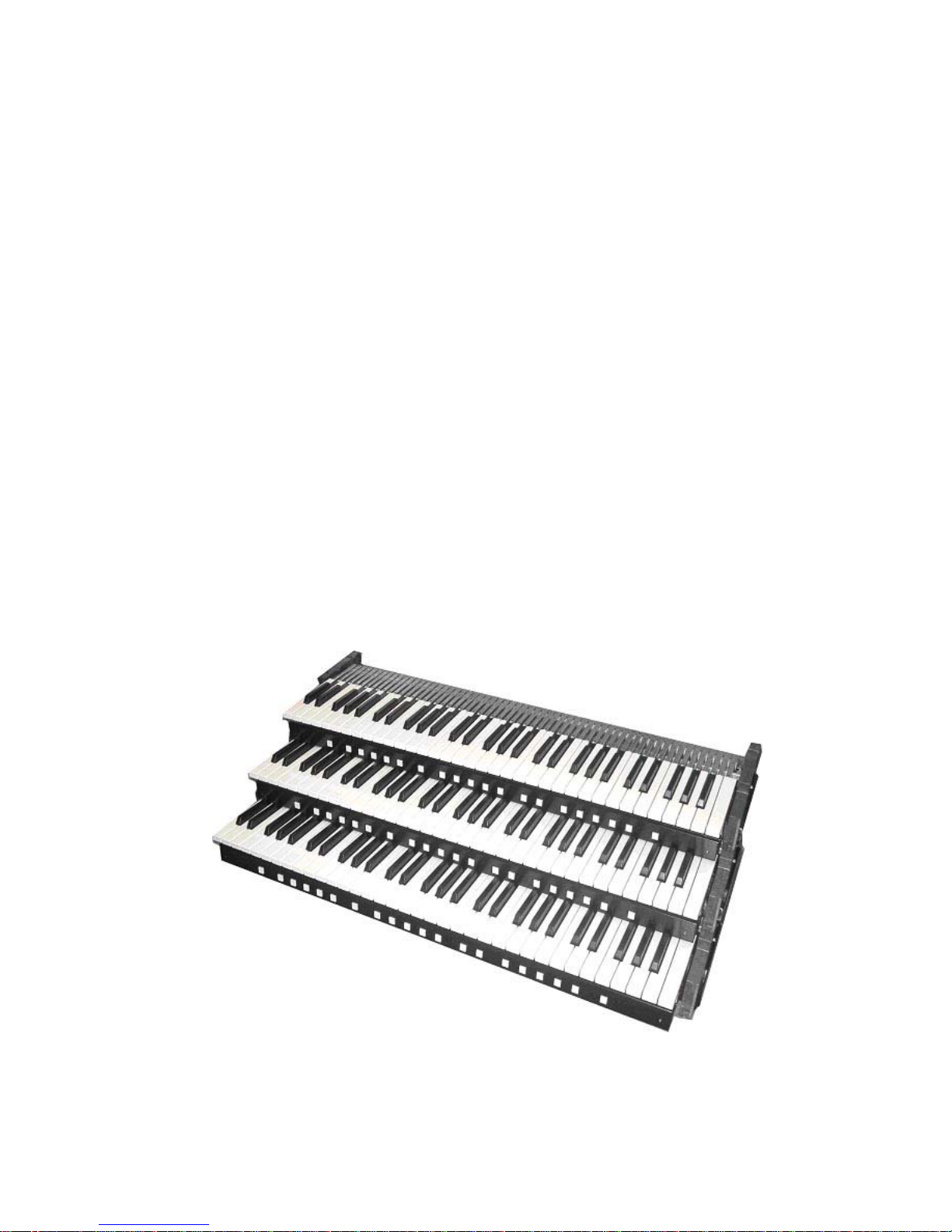
Figure 1: CMK-2 components:
A) Keyboard
B) Fatar small mounting bracket
C) Fatar large mounting bracket
D) 9 to 12V DC wall adaptor
E) 6-Ft. MIDI cable
F) Mounting screw.
* Adaptor is 9V 1A for four keyboards. Normal one is 500 mA.
8 2009 CLASSIC ORGAN WORKS CMK-2 Manual 1.5.doc
MIDI KEYBOARD CMK-2 INTRODUCTION MANUAL v1.5
CMK-2 Manual 1.5.doc 2009 CLASSIC ORGAN WORKS 9
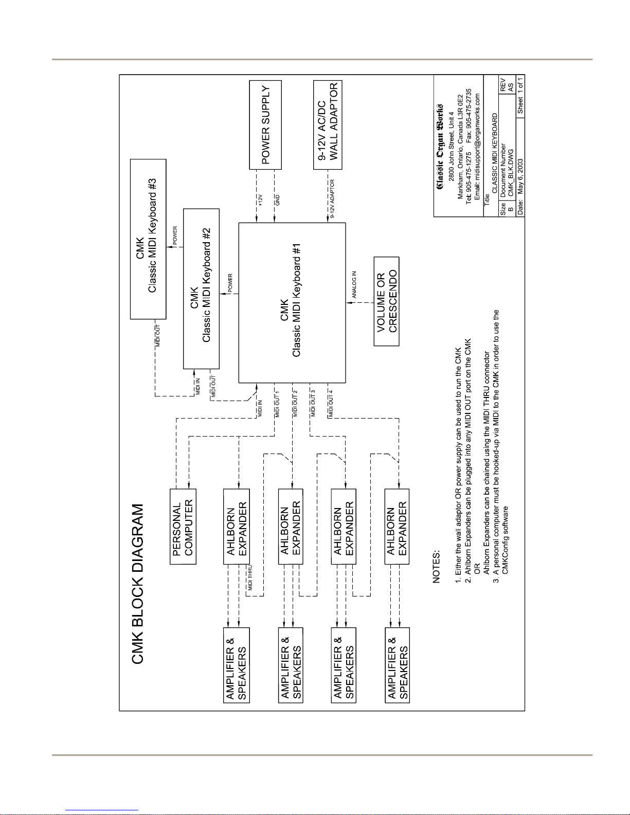
Figure 2: CMK-2 connections

MIDI KEYBOARD CMK-2 INSTALLATION MANUAL v1.5
CLASSIC MIDI KEYBOARD
CMK-2-1
3. INSTALLATION
IMPORTANT
READ THIS DOCUMENT BEFORE INSTALLATION
Upon receiving this unit, remove any packing material inside the unit that may have been included to
prevent movement of components or wiring during shipping.
(For internal access, ensure the unit is disconnected from all power sources.)
Physical Installation
The CMK-2 can be mounted into a traditional organ console or set on a table. The American Guild of Organists’
Standard Dimensions states that the top of the lowest manual’s keys must be 29.5" from the top of the E and F pedals.
If the standard Classic MIDI Pedalboard is used, the table will then be 32.5" from the floor.
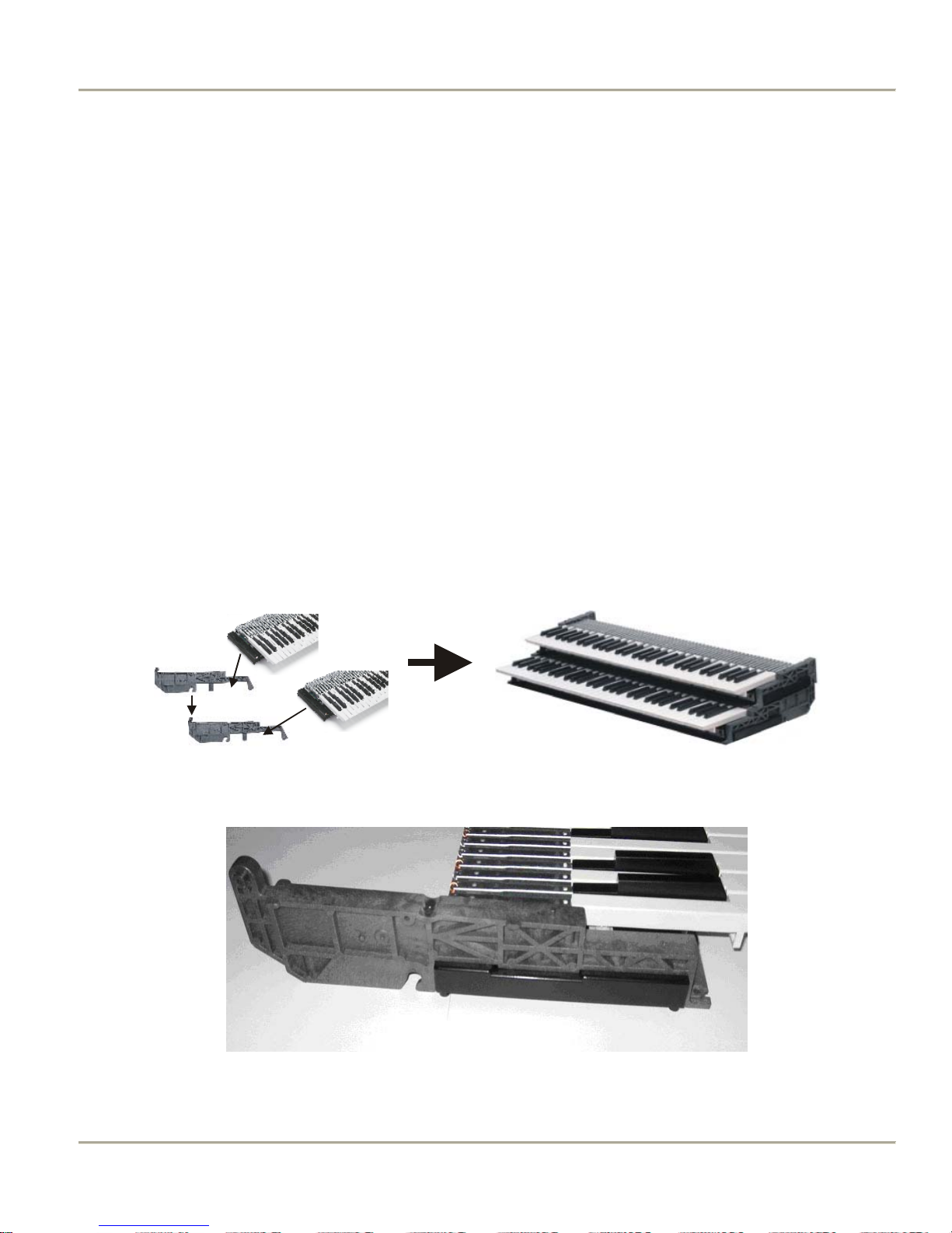
Figure 3: Bracket Installation
Figure 4: Bracket Goes above Keyboard Mount
CMK-2 Manual 1.5.doc 2009 CLASSIC ORGAN WORKS 11
MIDI KEYBOARD CMK-2 INSTALLATION MANUAL v1.5
First, note that the topmost keyboard should have the two shortest brackets. Then, sit the plastic supports on the end of
each keyboard (Figure 4) and fasten them in place with three #8 screws from underneath (Figure 5). Stack the
keyboards by sliding the slots on the upper supports over the pins on the lower supports. To slide the upper supports
into place, first tilt the keyboard up about 30 degrees. At that angle, the pins on the lower supports will slide through
the slots on the upper supports.
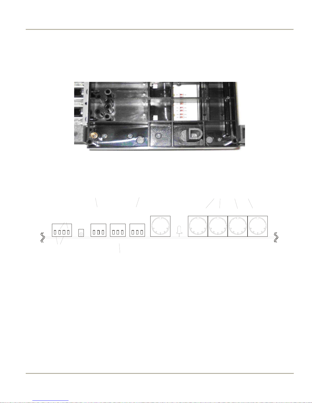
Connectors
POWER
TERMINAL
BLOCK
+12V
ABBA
GND
Figure 5: Install three #8 Screws in the Underside
not used
DC 12V INPUT 3 INP UT 2 INPUT 1
+ O - + O - + O -
Standard swell-shoe input
Swell-shoe input for Ahlborn
Archive crescendo pedal
Figure 6: Rear View Connections
HEARTBEAT
LIG HT
parallel outputs (all the same)
MIDI OUTMIDI OUT MIDI OUTMIDI IN
MIDI OUT
12 2009 CLASSIC ORGAN WORKS CMK-2 Manual 1.5.doc
MIDI KEYBOARD CMK-2 INSTALLATION MANUAL v1.5
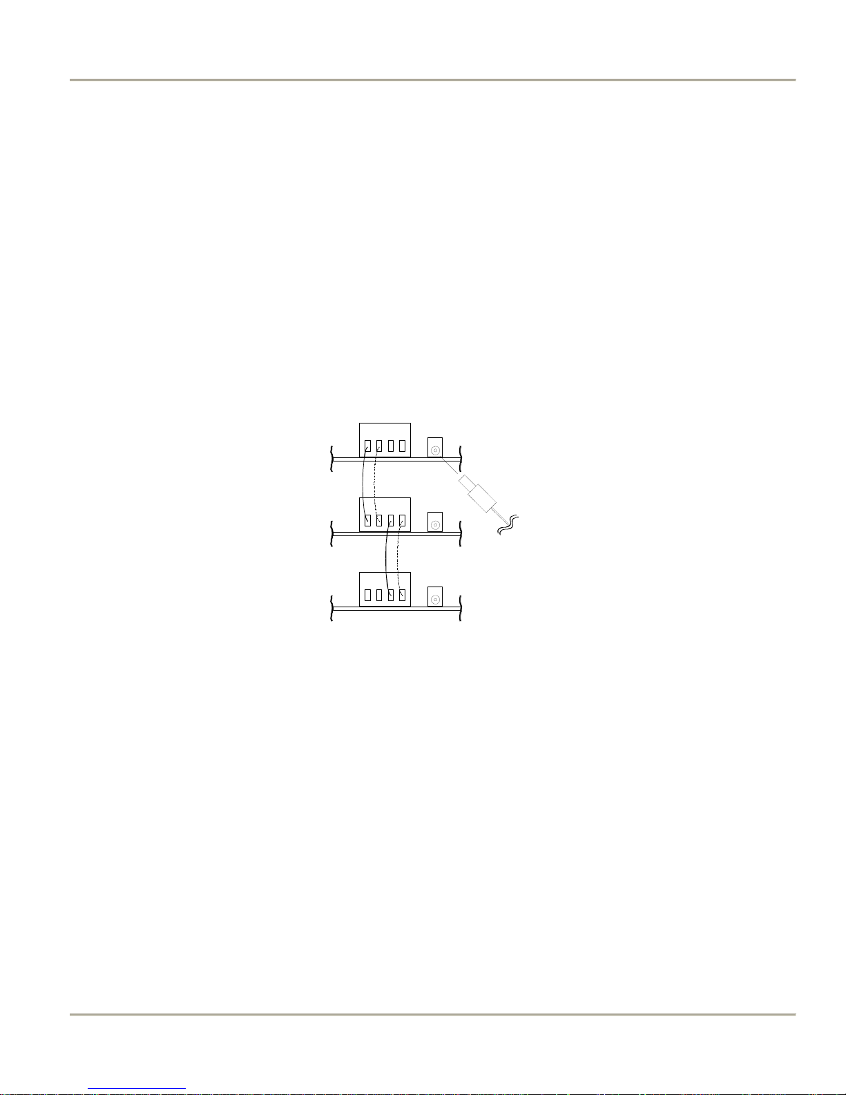
R
Power Connections
If you are using multiple keyboards, connect the red and black wires as illustrated in the diagram below (to parallel the
boards) and then connect the supplied DC power supply to the co-axial power connector on one board. The power
supply can be plugged into any one of the manuals. Make sure that you use red wires for the +12V (A terminals) and
black wires for the Ground (B terminals).
If you have a stack of four keyboards, you may use one power supply of 1 Amp capacity or two of 500 mA. If the
latter, parallel only two keyboards per power supply.
When the keyboard is powered and operating, the green ‘Heartbeat’ LED between the MIDI IN and MIDI OUT
connectors will be flashing.
POWE
TERMINAL
BLOCK
AABB
DC 12V
AABB
AABB
DC POWER
SUPPLY
Figure 7: Power Terminal Block Connections
Additional Information:
• If the CMK-2 is to be mounted in an existing organ, it can be connected to the organ power supply. See
Figure-33 in Appendix-C for details.
• The CMK-2 has a bridge-rectifier, and can accept power supplies with either positive or negative on the centre
pin of the 2.1mm (0.080") Co-axial Power Jack.
• The CMK-2 requires between +9V and +15V DC at a minimum current of 120 mA per board. The supplied
power supply (500 mA) is good for up to three keyboards. One with more current capability (typically 1 Amp)
should be used for four keyboards, or else use two smaller power supplies for two keyboards each.
• A 500mA self-resetting Polyfuse on each board provides over-current protection.
.
CMK-2 Manual 1.5.doc 2009 CLASSIC ORGAN WORKS 13
MIDI KEYBOARD CMK-2 INSTALLATION MANUAL v1.5
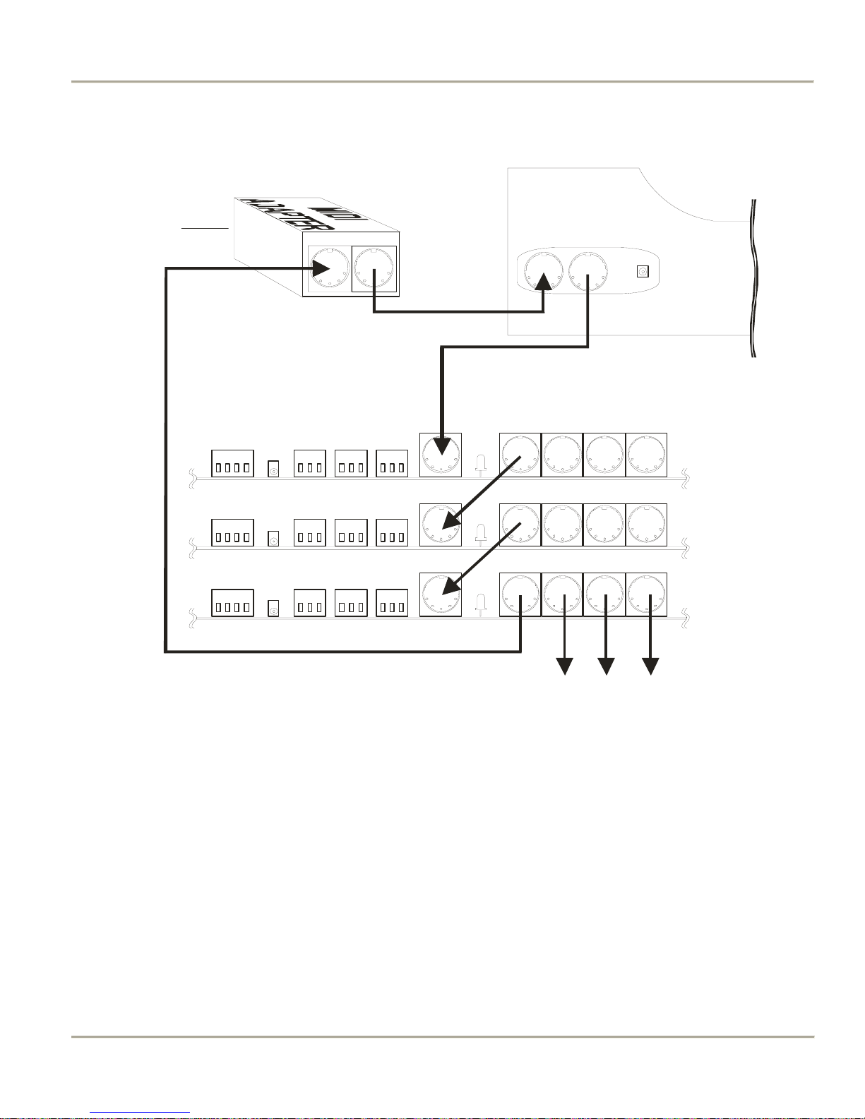
MIDI Connections
Connec ted
to PC
MIDI IN MIDI OUT
MIDI Adapter
MIDI OUTMIDI IN
Classic MIDI Pedalboard
(rear view)
MIDI OUT
MIDI OUTMIDI OUT MIDI OUTMIDI IN
Manual 1
MIDI OUT
MIDI OUTMIDI OUT MIDI OUTMIDI IN
Manual 2
MIDI OUT
MIDI OUTMIDI OUT MIDI OUTMIDI IN
Manual 3
Ahlborn Archive and
other MIDI Modules
Figure 8: Connecting Cables to a Keyboard Stack
Note: If you have more keyboards, they should be ‘daisy-chained’ in a similar manner at the bottom of the stack so
that #1(the top one) is always the first one connected to MIDI OUT on the computer (via the pedalboard if there is
one).
The MIDI OUT cable from the computer/adaptor is needed only during configuration. It should be unplugged during
normal use.
14 2009 CLASSIC ORGAN WORKS CMK-2 Manual 1.5.doc
MIDI KEYBOARD CMK-2 INSTALLATION MANUAL v1.5
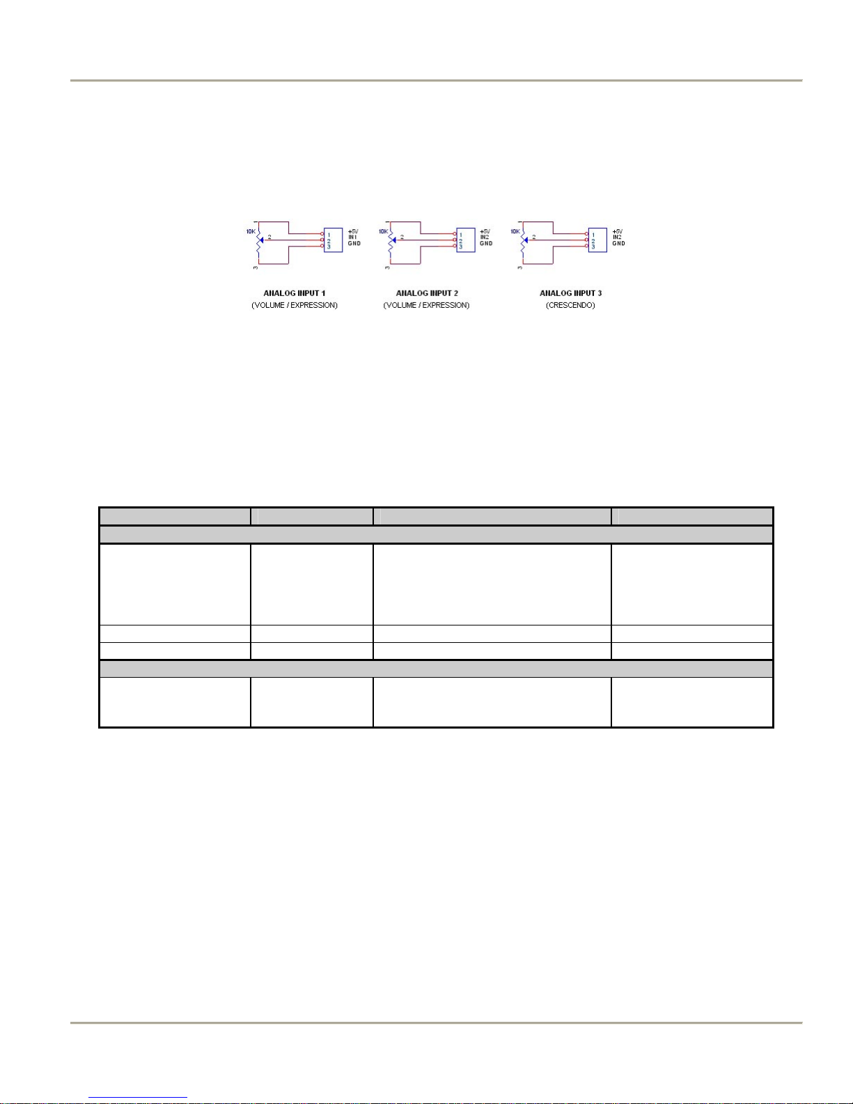
Connecting Swell Shoes
There are three terminal-blocks for analog inputs. Analog inputs are used for crescendo and volume/expression
adjustments. Schematics for analog and expression pedal inputs are shown below.
Figure 9 Wiring Schematic for Analog inputs
The +5V and Ground are supplied by the CMK board. Ensure that the slider is the centre pin of the three. Then the
control can be easily reversed if necessary.
Analog Inputs 1 to 3 can be used for any kind of analog input control and configured by the CMK-2 Config software
or the setup key sequence described in the Programming sections 5 and 6. The +5V is supplied by the CMK-2.
Table 2: Connection Chart
Connection Name Connection Type Hardware Description
Required Connections:
Power Input 1. Co-ax 2.1mm (either polarity)
MIDI IN Input DIN 5-pin socket 180° Standard MIDI signals
MIDI OUT 1-4 Output DIN 5-pin socket 180° Standard MIDI signals
Optional Connections:
Analog
JP-1, 5, 8
OR
2. 4-input Terminal Block
Input 1 for +12V, Input 2 for GND
Input 3-input terminal blocks
Screw terminals
9-12V, 120mA minimum
Per CMK-2.
Loop through to other
CMK-2s.
Three inputs available.
+5V and 0V provided by
the CMK-2
CMK-2 Manual 1.5.doc 2009 CLASSIC ORGAN WORKS 15

MIDI KEYBOARD CMK-2 INSTALLATION MANUAL v1.5
Software Installation (Windows1 and MacIntosh users2)
Software installation instructions are described in the ‘CMK Configuration Software’ section of the manual, and under
the Help menu of that software (Windows only).
Note: To use the software, the CMK-2 must be connected to a computer via MIDI. If a MIDI port is not available on
your computer, a commercial MIDI adapter for the game port, USB port, or parallel port may be used. A suitable one
is the M-Audio MIDIman 1x1 that comes with both Windows and MacIntosh drivers.
1
Windows is a registered Trademark of the Microsoft Corporation.
2
MacIntosh is a registered Trademark of Apple Computer Corporation.
16 2009 CLASSIC ORGAN WORKS CMK-2 Manual 1.5.doc
MIDI KEYBOARD CMK-2 MIDI SPECIFICATION MANUAL v1.5
CLASSIC MIDI KEYBOARD
CMK-2-1
4. MIDI SPECIFICATION
MIDI (Music Instrument Digital Interface) is a communication system between computer-controlled music
instruments and describes all the actions of a musical performance. It was originally developed for music synthesizers
but, a few years ago, organ-builders began adding MIDI capabilities to pipe organs. However, as MIDI was not
designed for a complex musical instrument such as the organ, its standards are subject to organ-builders preferences.
MIDI is composed of three components which are the language (protocol), hardware (MIDI connector), and
distribution format (MIDI file)
of bits at 31.25 KBits per second with 10 bits transmitted per byte. The 10 bits per byte consist of a start bit, 8 data
bits, and a stop bit. In the hardware domain, the MIDI 1.0 Specification (maintained by the MIDI Manufacturers
Association) recommends the 5-pin DIN 180° connector. The 5-pin DIN connector is standard and allows MIDI
equipment from differing manufacturers to be connected together. MIDI cables transmit information in a unidirectional manner so connectors are designated as either input or output. MIDI files are the standard distribution
format. They capture all the details of MIDI onto a hardcopy medium. MIDI files are similar to the MIDI language
except that they add a time-stamp for each event so that MIDI equipment can replicate the timing required to generate
accurate performances. MIDI Message information can be found at www.midi.org
The standard MIDI sounds available with General MIDI are listed in Appendix-F.
Ahlborn
The Ahlborn Archive modules allow additional pipe organ sounds to be played on an existing organ. There are four
separate Ahlborn Archive modules of 20 different stops each over three separate divisions. For more information on
Ahlborn Archive modules, please visit: http://www.ahlbornorgans.com/archive
Archive modules can be found in Appendix D. The stop list for each module is shown below.
[2]
:
Table 3: Classic Module
Description Description Description
Gemshorn 8' Principal 8' Contre Basse 32'
Gemshorn Celeste 8' Holzgedackt 8' Contre Gambe 16'
Flûte à cheminée 8' Flûte Harmonique 8' Contre Bombarde 32'
Koppelflöte 4' Flûte Octaviante 4' Bombarde 16'
Plein Jeu IV-V Octave 2' Div. A to Ped.
Bombarde 16' Cymbale III Div. B to Ped.
Harmonic Trumpet 8' Tremulant
Corno di Bassetto 8' Div. A to Div. B
Festival Trumpet 8'
Div. B to Div. A
[1]
. The MIDI language is in binary format and is a uni-directional asynchronous stream
.
. The messages for controlling Ahlborn
[3]
Division A Division B Pedal
Clarion 4'
Tremulant
CMK-2 Manual 1.5.doc 2009 CLASSIC ORGAN WORKS 17
MIDI KEYBOARD CMK-2 MIDI SPECIFICATION MANUAL v1.5
Table 4: Romantic Module
Division A Division B Pedal
Description Description Description
Cello 8' Open Diapason 8' Contre Violone 32'
Cello Celeste 8' Flauto Mirabilis 8' Contre Gambe 16'
Cornet des Bombardes IV Concert Flute 4' Contre Bassoon 32'
Cornopean 16' Quint Flute 2 2/3' Ophicleide 16'
Clarinet 8' Piccolo 2' Div. A to Ped.
Orchestral Oboe 8' Vox Humana 8' Div. B to Ped.
French Horn 8' Tremulant
Cor Anglais 8' Div. A to Div. B
Tuba Mirabilis 8'
Clarion 4'
Tremulant
Div. B to Div. A
[3]
Table 5: 201 Module
[3]
Division A Division B Pedal
Description Description Description
Bourdon 16' Gedackt 8' Subbass 16'
Principal 8' Gamba 8' Octave 8'
Flûte à cheminée 8' Nachthorn 4' Bourdon 8'
Unda Maris 8' Cymbale III Posaune 16'
Octave 4' Cornet III Div. A to Ped.
Spitzflöte 2' Oboe 8' Div. B to Ped.
Nasard 2 2/3' Tremulant
Superoctave 2' Div. A to Div. B
Mixture IV
Trompete 8'
Tremulant
Div. B to Div. A
Table 6: 202 Module
[3]
Division A Division B Pedal
Description Description Description
Contregambe 16' Bourdon 8' Soubasse 32'
Diapason 8' Flûte harmonique 8' Violone 16'
Quintadena 8' Flûte octaviante 4' Contrebombarde 32'
Terz 1 3/5' Larigot 1 1/3' Bombarde 16'
Septime 1 1/7' Corno di bassetto 8' Div. A to Ped.
Scharff III Clarion 4' Div. B to Ped.
Bombarde 16' Tremulant
Trompette 8' Div. A to Div. B
Tuba Mirabilis 8'
Chimes
Tremulant
Div. B to Div. A
18 2009 CLASSIC ORGAN WORKS CMK-2 Manual 1.5.doc
MIDI KEYBOARD CMK-2 MIDI SPECIFICATION MANUAL v1.5
HAUPTWERK II
TM [4]
The CMK-2 provides an interface for volume controls, expression controls, and pistons. MIDI messages will then be
sent through the MIDI OUT port to the personal computer where Hauptwerk software will translate the MIDI message
commands into actions on the organ. Table-7 shows the types of messages sent for the individual functions:
Table 7: MIDI messages relevant to Hauptwerk
Function MIDI command
Keyboards &
Pedalboard
Stops Note on/off
Pistons Program change
Volume Program change (Controller-7)
Expression Program change (Controller-7)
Crescendo Program change
Table 8: Default Configuration for Hauptwerk
Physical Position
Solo 5 #1 (Top) *
Swell 3 #2
Great 2 #3
Choir 4 #4 (Bottom) *
Pedal 1 n/a
Cresc. Shoe 7 any
Swell Shoe 3 #3
Choir Shoe 4 #4 *
* If you have fewer keyboards, their MIDI Channel numbers are simply omitted and the Configuration Order changed
to suit with your top keyboard as #1, but the Crescendo should remain on MIDI Channel-7. This table assumes you are
using our pedalboard and that it is wired and connected as per Figure-6. Crescendo can wired to any keyboard as long
as it sends its message on Channel-7. The setup in Hauptwerk can be configured to suit. The pedalboard does not use a
CMK-2 board so is not configurable by this software.
For more information, or to download a shareware version of Hauptwerk software, please visit:
http://www.crumhorn-labs.com
SCPOP
TM
Sound Canvas Pipe Organ Project (SCPOP) is a computer program that emulates organ features like stop changes,
keyboard coupling, tremolo, assignable memories, temperament changes, and the ability to choose different reverb
settings. All of the features can be accessed using the computer keyboard’s keys like a true organ console.
SCPOP requires a Roland Sound Canvas MIDI Expander module and is only compatible with Roland hardware
containing the ‘Sound Canvas’ label
[6]
. The messages used to control SCPOP can be found in Appendix E.
1. Note on/off
2. Channel number
3. Key number
CMK Config Software
CMK Config
MIDI Channel
CMK Config
Order *
[5]
CMK-2 Manual 1.5.doc 2009 CLASSIC ORGAN WORKS 19
MIDI KEYBOARD CMK-2 MIDI SPECIFICATION MANUAL v1.5
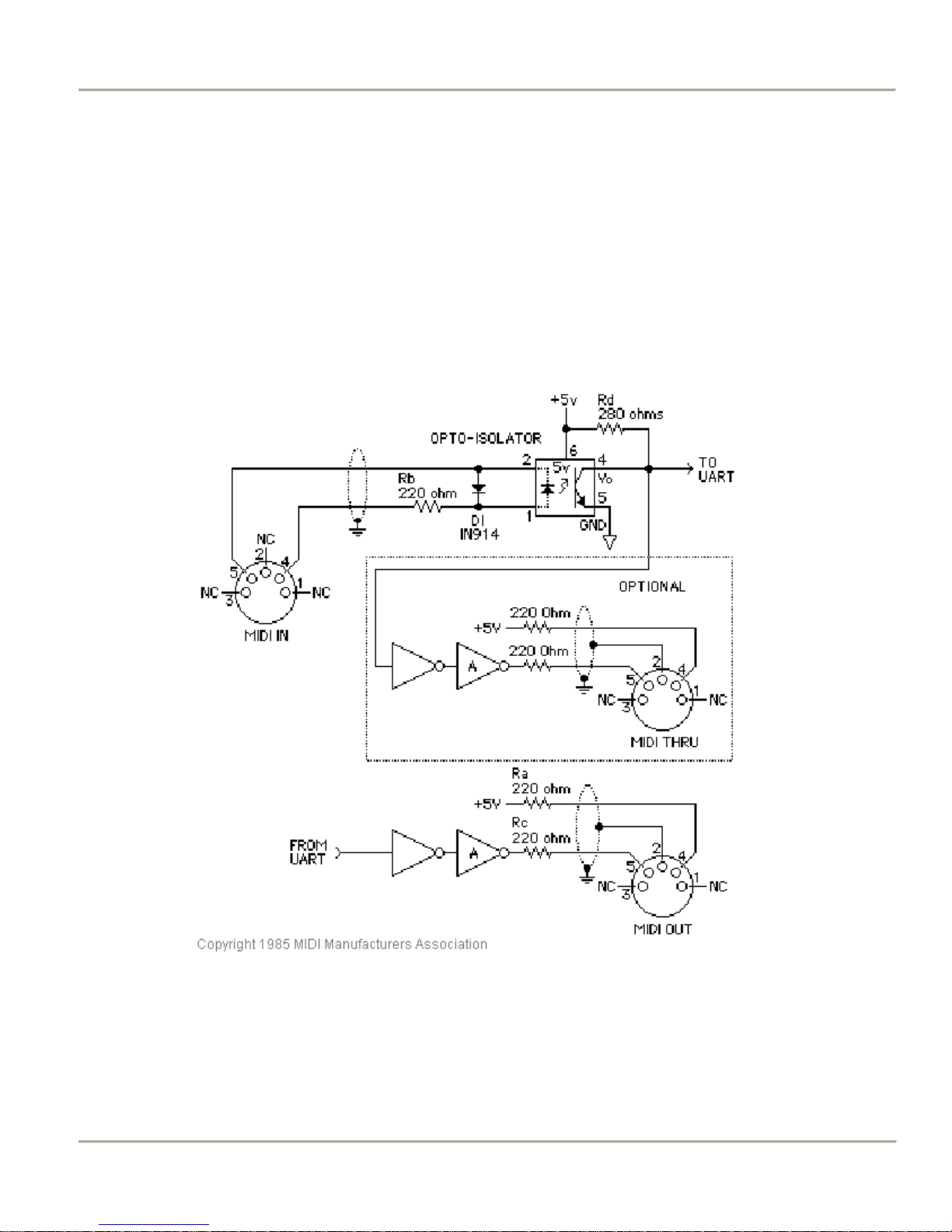
[1]
MIDI Hardware Specification
The only MIDI connector approved by the MIDI Manufacturers Association is a 5-pin 180º DIN connector. There are
other ways of connecting devices to send MIDI messages but it is easier to have compatibility between different MIDI
devices if there is a standard connector. In connecting a MIDI device to a personal computer, the simplest way is
through the MIDI ports of a computer (MIDI connectors are uni-directional from the ‘OUT’ connector to the ‘IN’
connector). Due to space limitations of computer circuit boards, most computers are not equipped with a MIDI port.
Thus, adapters must be used that connect the MIDI device to another port. The most common port is the computer’s
game port that is found on most soundcards. Adapters are also available for the serial port, parallel port, and USB port.
A schematic of the 5-pin DIN connector typical interface is shown below: The basic signal is a negative-going pulse
on pin-5.
MIDI Hardware NOTES:
1. Opto-isolator shown is Sharp PC-900. HP 6N138 or other types can be used with changes.
2. Gates ‘A’ are Integrated Circuit or transistor; Resistors are 5%.
3. Maximum cable length is fifty feet (15 meters), terminated at each end by a 5-pin 180º DIN male plug (e.g. SWITCHCRAFT
05GM5M).
4. Cable is shielded twisted-pair, with shield connected to pin 2 at both ends.
5. MIDI In ground is not connected (to avoid Ground Loops).
20 2009 CLASSIC ORGAN WORKS CMK-2 Manual 1.5.doc
Figure 10: 5-pin DIN connections

MIDI KEYBOARD CMK-2 HARDWARE CONFIGURATION MANUAL v1.5
CLASSIC MIDI KEYBOARD
CMK-2-1
5. HARDWARE CONFIGURATION
Introduction
The CMK-2 is customizable to suit many organ applications. Up to four CMK-2 keyboards may be stacked level, or
tilted if the optional mounting brackets are purchased. Each keyboard has 61-keys that serve for programming as well
as musical purposes. Three useable analog inputs are available (for volume/expression and crescendo adjustment).
Note: While you can set the keyboard functions in this way, pistons must be set up using the Configuration software.
See 6. Software Configuration.
Power-On Self Test
The CMK-2 has a built-in self-test that executes upon power up.
Analog Input Pins
There are three analog inputs on the CMK-2, each with three-pin terminal blocks. Keyboard Analog devices must be
connected to the analog input pin ‘2’, a positive voltage (+5V) on pin ‘1’, and ground potential (0V) on pin ‘3’.
Depending on the position of the analog device, a voltage will be read by the processor that will determine the setting.
In the case of a volume control, the position of the analog device will determine the loudness level. See Figure 9.
MIDI Crescendo – for Ahlborn Archive modules
MIDI messages are sent to add stops progressively to a registration. ‘Analog Input 3’ is used for Crescendo.
MIDI Volume
A MIDI controller-7 message is sent to change the loudness level of the stop or sound (typically for Ahlborn Archive
modules). The MIDI volume analog input must be configured to transmit on one or more MIDI channels as outlined in
Table 9.
MIDI Expression
A MIDI controller-11 message is sent to set the loudness level within the preset volume range (typically for
Hauptwerk). ‘Analog Input 1’ is used for Expression but can also be used for Volume. Expression messages adjust the
loudness within a range not exceeding the maximum set by volume. The MIDI Expression analog input must be
configured to transmit on one or more MIDI channels as outlined in Table 8. In multi-manual CMK-2 setups, the range
for the Expression control can be set by attaching a Volume control to one of the keyboards and attaching an
Expression control to another keyboard. If the volume and expression controls are set to produce messages on the same
MIDI channels, the volume control will set the maximum range while the expression control will change the loudness
level in the volume range.
CMK-2 Manual 1.5.doc 2009 CLASSIC ORGAN WORKS 21

MIDI KEYBOARD CMK-2 HARDWARE CONFIGURATION MANUAL v1.5
Programming Keyboard Functions
The following chart lists the functions manually settable using only the piston pushbuttons and keyboard key-switches.
Table 9: Programming Functions
Name Steps Function
1. SOFT REBOOT
2. SET MIDI
CHANNEL(S)
ACTIVE
3. SET MIDI
CHANNEL(S)
INACTIVE
4. SET DEFAULT
VELOCITY
(if keyboard is presently
in the non-velocity
mode)
Simultaneously press the first piston
from the left (SET) and last piston on
the right (CANCEL).
Hold the first piston from the left (SET)
and momentarily press the first black
key from the left (C#1). While still
holding SET, momentarily press one or
more of the first 16 white keys from the
left (C1 to D3). Afterwards, release the
SET piston.
Hold first piston from the left (SET)
and momentarily press the second black
key from the left (D#1). Afterwards,
release the SET piston.
Hold the first piston from the left (SET)
and momentarily press the third black
key from the left (F#1). Then
momentarily press any one of the 36
white keys and release the SET piston.
Repeating the above will set the next
active MIDI channel that has velocitysensing turned Off.
Performs a soft reboot. This will restart the keyboard and reload
configuration data from the on-board EEPROM.
Sets the output MIDI channels for the keyboard. For example, if
we configure the keyboard to transmit on channels 1, 3 and 5,
then all MIDI events originating from that keyboard will produce
MIDI messages on these three channels. C1 for Channel-1, E1
for Channel-3, G1 for Channel-5, etc.
Clears all output MIDI channels for the keyboard. You cannot
clear just one but must clear all and start again as above.
You can change just one by using the configuration software.
Selects the default velocity for the lowest-numbered active MIDI
channel with velocity-sensing set Off. Uses the white keys to
select a velocity level between 0 (bass end: softest) and 127
(treble end: loudest). Keys pressed in between will produce a
velocity level between 0 and 127 proportional to the location of
the key relative to the extremes. The change in velocity level
between adjacent white keys is approximately 3.
Note that if multiple keys are pressed, only the last one released
will be registered by the software.
5. SET VELOCITY
SENSING OFF
6. SET VELOCITY
SENSING ON
Hold the first piston from the left (SET)
and momentarily press the fourth black
key from the left (G#1) to turn off
velocity sensing. Afterwards, release the
SET piston.
The MIDI Channel with the lowest
active number will be set to velocitysensing Off and will use the default
velocity value.
Hold first piston from the left (SET)
and momentarily press the fifth black
key from the left (A#1) to turn on
velocity sensing. Afterwards, release the
SET piston.
The MIDI Channel with the lowest
active number that is presently in the
Velocity-sensing Off mode will be set to
velocity-sensing On.
Velocity sensing produces a different volume level corresponding
to the speed with which a key is pressed. To conform to
traditional organ consoles which are not velocity sensitive, the
CMK-2 permits users to disable velocity-sensing in the keyboard.
Velocity sensing produces a different volume level corresponding
to the speed with which a key is pressed. To conform to
traditional organ consoles which are not velocity sensitive, the
CMK-2 permits users to disable velocity-sensing in the keyboard.
22 2009 CLASSIC ORGAN WORKS CMK-2 Manual 1.5.doc
 Loading...