

Dmbttjd!Pshbo!Xpslt!
CMK-1
Classic MIDI Keyboard
User Manual
Version 1.00.05
Div. of:
ARTISAN CLASSIC ORGAN INC.


CLASSIC MIDI KEYBOARD
CMK-1
TABLE OF CONTENTS
LIMITED WARRANTY ............................................................................................... 9
INTRODUCTION ...................................................................................................... 11
Description....................................................................................................................................11
Table 1: Parts/Components List ...............................................................................................................................12
Figure 1: CMK components ..................................................................................................................................... 12
Figure 2: CMK connections .....................................................................................................................................13
INSTALLATION ....................................................................................................... 15
Springs ..........................................................................................................................................15
Figure 3: Steps in replacing a dislocated spring...................................................................................................... 15
Mounting .......................................................................................................................................15
Figure 4: Single-manual stand-alone....................................................................................................................... 16
Figure 5: Single-manual with wooden case............................................................................................................. 16
Figure 6: Two manual setup .................................................................................................................................... 16
Figure 7: Three manual setup.................................................................................................................................. 17
Figure 8: Two/Three-manual setup mounted level .................................................................................................. 17
Figure 9: Two/Three-manual setup mounted ‘tilt-up’ ............................................................................................... 18
Figure 10: Accessing keyboard electronics ............................................................................................................. 18
Connections..................................................................................................................................18
Power....................................................................................................................................................................... 18
Figure 11: Connecting Multiple CMK Keyboards, Rear View, Using Parallel Wiring and Included Power Supply . 19
MIDI .........................................................................................................................................................................19
Figure 12: MIDI Connection Jacks, Rear View........................................................................................................ 19
Analog Inputs........................................................................................................................................................... 20
Figure 13: Wiring Schematic for Analog input ......................................................................................................... 20
Table 2: Connection Chart........................................................................................................................................ 20
Software Installation (Windows users only)............................................................................................................. 21
MIDI SPECIFICATION ............................................................................................. 22
MIDI Sound Sets ...........................................................................................................................22
General MIDI............................................................................................................................................................22
Table 3: Sound Set Groups ...................................................................................................................................... 23
Table 4: General MIDI Program Numbers for MIDI Channels 1-9 and 11-16.......................................................... 24
Table 5: General MIDI Percussion Key Map for MIDI Channel 10........................................................................... 25
Ahlborn..................................................................................................................................................................... 25
Table 6: Classic Module ...........................................................................................................................................25
_________________________________________________________________________________________________________
CMK-1 Manual (Issue-1)
Page-3 October 20, 2004

Table 7: Romantic Module........................................................................................................................................ 26
Table 8: 201 Module ................................................................................................................................................. 26
Table 9: 202 Module ................................................................................................................................................. 26
HAUPTWERKTM.......................................................................................................................................................27
Table 10: MIDI messages relevant to Hauptwerk ....................................................................................................27
SCPOPTM.................................................................................................................................................................27
MIDI Hardware Specification .......................................................................................................28
Figure 14: Schematic of 5-pin DIN connector.......................................................................................................... 28
CMK HARDWARE CONFIGURATION.................................................................... 29
Introduction...................................................................................................................................29
Power-On Self Test.......................................................................................................................29
Analog Input Pins ......................................................................................................................... 29
MIDI Crescendo ....................................................................................................................................................... 29
MIDI Volume ............................................................................................................................................................ 29
MIDI Expression.......................................................................................................................................................29
Programming ................................................................................................................................30
Table 11: Piston programming functions .................................................................................................................. 30
CMK SOFTWARE CONFIGURATION..................................................................... 32
Introduction...................................................................................................................................32
Software Installation.....................................................................................................................32
Figure 15: Upon clicking on the ‘CMK_Setup.exe’ file, the above window will appear. .......................................... 33
Figure 16: Allows the user to select a directory to install the CMK program file .....................................................33
Figure 17: Setup adds an icon to the start menu for convenient access.................................................................34
Figure 18: Setup provides the option of creating an icon on the Windows desktop................................................ 34
Figure 19: Confirmation window .............................................................................................................................. 35
Figure 20: Setup progress window .......................................................................................................................... 35
Figure 21: Confirms installation was successful...................................................................................................... 36
Software Startup ...........................................................................................................................37
Figure 22: CMKConfig software startup screen....................................................................................................... 37
Figure 23: CMKConfig software main menu............................................................................................................ 37
Configure a CMK from scratch....................................................................................................38
Figure 24: CMKConfig software attempting to connect with the CMK ....................................................................38
Figure 25: CMKConfig software unable to connect................................................................................................. 38
Figure 26: CMKConfig software successfully connected to the CMK. .................................................................... 38
Figure 27: Successful connection between CMKConfig software and CMK........................................................... 39
Figure 28: Window confirms the loading of pre-configuration data from the CMK to the PC.................................. 39
Load a previously saved CMK configuration .............................................................................40
Figure 29: Configuration File selection window. ...................................................................................................... 40
Figure 30: Program window..................................................................................................................................... 40
_________________________________________________________________________________________________________
CMK-1 Manual (Issue-1)
Page-4 October 20, 2004

Functions of the Toolbars............................................................................................................41
Figure 31: Toolbars in CMKConfig software............................................................................................................ 41
1. File Menu ............................................................................................................................................................ 41
Figure 32: Loading Program Data From File Window ............................................................................................. 41
Figure 33: Save Program Data to File Window ....................................................................................................... 42
Figure 34: Confirm replacing of file window............................................................................................................. 42
Figure 35: Software attempting to make a connection with the CMK...................................................................... 43
Figure 36: Software unable to make a connection with the CMK............................................................................ 43
Figure 37: Software detecting number of keyboards............................................................................................... 43
Figure 38: Successful connection between CMK and PC software ........................................................................ 44
Figure 39: Confirms loading of configuration into CMKConfig software.................................................................. 44
Figure 40: Software attempting to communicate with CMK ...................................................................................44
Figure 41: Successful Software connection to the CMK ......................................................................................... 45
Figure 42: Confirms configuration written to CMK from CMKConfig software. .......................................................45
2. Options Menu...................................................................................................................................................... 45
Figure 43: MIDI Input Output Setup window............................................................................................................ 45
2. Help Menu...................................................................................................................................................... 46
Figure 44: Help Menu .............................................................................................................................................. 46
Keyboard Functions .....................................................................................................................46
Figure 45: Clicking on the keys of the keyboard invokes a MIDI Channel select menu.......................................... 47
Figure 46: Clicking on an individual piston invokes the Piston function select drop-down menu. ..........................47
Table 12: Customizable Functions for each piston ..................................................................................................48
Configuring Multiple Keyboards .................................................................................................49
REFERENCES ......................................................................................................... 51
APPENDIX A: .......................................................................................................... 53
DIP SWITCH CONFIGURATION TABLE ................................................................ 53
Table 13: DIP Switch settings and their corresponding Configuration numbers...................................................... 53
APPENDIX B: .......................................................................................................... 56
MIDI PROTOCOL SPECIFICATION ........................................................................ 56
MIDI Protocol Specification .........................................................................................................56
Channel Messages ..................................................................................................................................................56
System Messages.................................................................................................................................................... 57
Running Status ........................................................................................................................................................ 57
Table 14: MIDI 1.0 Specification Message Summary ..............................................................................................58
Table 15: Expanded Status Bytes List...................................................................................................................... 61
Table 16: Control Changes and Mode Changes ...................................................................................................... 64
Table 17: Registered Parameter Numbers...............................................................................................................67
APPENDIX C: .......................................................................................................... 69
SYSTEM EXCLUSIVE MESSAGE LAYOUTS ........................................................ 69
_________________________________________________________________________________________________________
CMK-1 Manual (Issue-1)
Page-5 October 20, 2004

Messages common to all products............................................................................................. 69
General Information Identity Request...................................................................................................................... 69
General Information Identity Reply .......................................................................................................................... 69
CMK -- Special layouts .................................................................................................................69
APPENDIX D: .......................................................................................................... 71
AHLBORN MESSAGES .......................................................................................... 71
Table 18: Note On/Off MIDI functions to control Ahlborn Archive sound modules ..................................................71
Table 19: Ahlborn Archive ‘ROMANTIC’ sound module commands for stops and couplers ................................... 72
Table 20: Ahlborn Archive ‘CLASSIC’ sound module commands for stops and couplers on.................................. 73
Table 21: Ahlborn Archive ‘202’ sound module commands for stops and couplers................................................. 74
Table 22: Ahlborn Archive ‘201’ sound module commands for stops and couplers................................................. 75
Table 23: Ahlborn Archive sound module Piston and Crescendo input functions for all four units.......................... 76
Table 24: Ahlborn Archive sound module additional Piston input commands .........................................................77
Table 25: Ahlborn Archive and other MIDI sound modules analog input function commands................................. 77
APPENDIX E:........................................................................................................... 79
SCPOP MESSAGES................................................................................................ 79
Table 26: General MIDI Pipe Organ Emulation Upper Manual for SCPOP ............................................................. 79
Table 27: General MIDI Pipe Organ Emulation Lower Manual SCPOP ..................................................................81
Table 28: General MIDI Pipe Organ Emulation Pedals SCPOP .............................................................................. 84
APPENDIX F:........................................................................................................... 85
CIRCUIT BOARD SCHEMATICS ............................................................................ 85
Figure 47: CMK1-1 Classic MIDI Keyboard Circuit board 1 Silk Screen................................................................. 85
Figure 48: CMK1-1 Classic MIDI Keyboard Circuit board 1 schematic................................................................... 86
Figure 49: CMK1-2 Classic MIDI Keyboard Circuit board 2 Silk Screen................................................................. 87
Figure 50: CMK1-2 Classic MIDI Keyboard Circuit board 2 schematic................................................................... 88
Figure 51: CMKPR1-1 Classic MIDI Keyboard Piston Rail board 1 Silk Screen..................................................... 89
Figure 52: CMKPR1-1 Classic MIDI Keyboard Piston Rail board 1 schematic....................................................... 90
Figure 53: CMKPR1-2 Classic MIDI Keyboard Piston Rail board 2 Silk Screen..................................................... 91
Figure 54: CMKPR1-2 Classic MIDI Keyboard Piston Rail board 2 schematic....................................................... 92
APPENDIX G: .......................................................................................................... 93
MECHANICAL DRAWINGS..................................................................................... 93
Figure 55: Two-manual CMK mounted level ........................................................................................................... 93
Figure 56: Two-manual CMK mounted tilted-up...................................................................................................... 94
Figure 57: Three-manual CMK mounted level......................................................................................................... 95
Figure 58: Three-manual CMK mounted ‘tilt-up’...................................................................................................... 96
Figure 59: CMK Piston Rail front panel mechanical drawing .................................................................................. 97
Figure 60: CMK Piston Rail Mounting rail mechanical drawing............................................................................... 98
Figure 61: CMK Piston Rail circuit board mounting rail mechanical drawing.......................................................... 99
Figure 62: CMK Side mounting bracket mechanical drawing (treble end) ............................................................ 100
Figure 63: CMK Side mounting bracket mechanical drawing (bass end)..............................................................101
_________________________________________________________________________________________________________
CMK-1 Manual (Issue-1)
Page-6 October 20, 2004

Figure 64: CMK End clamp mechanical drawing................................................................................................... 102
Figure 65: CMK two-manual mounting bracket mechanical drawing .................................................................... 103
Figure 66: CMK three-manual mounting bracket mechanical drawing.................................................................. 104
DISCLAIMER ......................................................................................................... 105
_________________________________________________________________________________________________________
CMK-1 Manual (Issue-1)
Page-7 October 20, 2004


CLASSIC MIDI KEYBOARD
CMK-1
LIMITED WARRANTY
Classic Organ Works warrants the Classic MIDI Keyboard (CMK) to be free from defects in materials and
workmanship under normal use for a period of ONE YEAR from the delivery date. This warranty applies
only if the product is owned by the original purchaser who has the bill of sale.
This warranty explicitly excludes any cables provided with the CMK, which may become defective as a
result of normal wear and tear. The DC power adaptor is included in the warranty however.
In the event of a defect in materials or workmanship, please contact Classic Organ Works immediately. In
particular, defects due to shipping should be reported within 15 days for insurance claim purposes. For all
other defects, Classic Organ Works agrees to repair or replace all defective parts of said products which are
returned, transportation prepaid, for inspection at its service centre within the period of the warranty.
In the event that Classic Organ Works determines the product requires repair because of user misuse or
regular wear, it will assess a fair repair or replacement fee. The customer will have the option to pay this fee
and have the unit repaired and returned, or not pay this fee and have the unit returned un-repaired.
Classic Organ Works will not be liable for consequential, special, indirect, or similar damages or claims
including loss of profit or any other commercial damage, and in no event will Classic Organ Works’ liability
for any damages to the purchaser or any other person exceed the price paid for the product, regardless of any
form of the claim. Classic Organ Works specifically disclaims all other warranties, expressed or implied.
Specifically, Classic Organ Works makes no warranty that the product is fit for any particular purpose.
This warranty shall be interpreted, and governed by applicable laws in the province of Ontario, Canada. If
any provision of this warranty is found void, invalid or unenforceable, it will not affect the validity of the
balance of the warranty, which shall remain valid and enforceable according to its terms. In the event any
remedy hereunder is determined to have failed of its essential purpose, all limitations of liability and
exclusion of damages set forth herein shall remain in full force and effect.
_________________________________________________________________________________________________________
CMK-1 Manual (Issue-1)
Page-9 October 20, 2004


CLASSIC MIDI KEYBOARD
CMK-1
INTRODUCTION
Description
Congratulations! You are now the proud owner of the CMK (Classic MIDI Keyboard). The CMK combines
technology and classical church organ ideas into an innovative MIDI device. With the CMK, MIDI sound modules
may be controlled as if they were part of the organ. Designed as a portable unit, it features a ‘stackable’ feature so that
users may customize a complete practice organ to their specification. With a quality construction, various structural
and electronic design elements, and user-friendly configuration software, the CMK will provide many years of worryfree musical enjoyment for all users.
The CMK is designed for organists, organ enthusiasts, and MIDI users. Key-switch information from the keyboard
and pistons is converted into MIDI control data by the on-board micro-controller. For instance, a MIDI message
defines whether a key was pressed or released, the MIDI channel that the information should be transmitted on and the
key number pressed or released. As many as three CMK keyboards may be daisy-chained.
Each CMK keyboard also has 20 pistons to control features such as coupling and effects. The CMK can
simultaneously drive up to four Ahlborn Archive Series™ modules that generate pipe-organ voices. In addition, any
MIDI-controlled sound module or PC-based synthesizer software may be connected. These pistons are also used for
programming the CMK. Combinations of pistons and keyswitches are used for functions such as a reboot, setting the
MIDI output channel, turning on and off velocity sensing, and setting the volume output.
There are two analog inputs which can be configured as volume/expression and crescendo inputs. By adjusting the
analog device, a unique voltage reading is produced on the analog input pin which is interpreted by the
microprocessor. In the case of a volume adjustment, a MIDI message will send to the MIDI-controlled device the
loudness level of the stop or sound. MIDI messages are also sent for a crescendo adjustment which will gradually add
stops to a registration.
The CMK is completely customizable using the included ‘CMKConfig’ software. Up to 128 configurations may be
programmed into the CMK. As many as three keyboards each with twenty pistons and two analog inputs may be
configured for Ahlborn Archive
software. The software is capable of customizing the CMK for use with organ computer simulation software such as
Hauptwerk and the Sound Canvas Pipe Organ Project (SCPOP).
Configurations are saved as computer files which may be stored in the user’s home computer, or in the CMK.
Configurations that are saved on the CMK will not be lost when power is turned off because the memory is nonvolatile. These configurations may be selected using DIP-switches on the CMK. Eventually, users may inexpensively
upgrade their software as well as configurations by visiting the Classic Organ Works website at
http://www.organworks.com
modules, General MIDI sound modules, and MIDI-controlled PC-based synthesizer
.
_________________________________________________________________________________________________________
CMK-1 Manual (Issue-1)
Page-11 October 20, 2004

The following is a list of parts for each CMK setup.
Table 1: Parts/Components List
Setup Items
A B C D E F
Manual(s) 2-Manual
Side Bracket
set (sold
separately)
One Manual 1 - 1 1
One Manual and
Wood Case
Two Manuals 2 2 1 2 4
Three Manuals 3 - 2 1 3 6
1 - 1 1
3-Manual
Side Bracket
set (sold
separately)
12V DC
adaptor
MIDI
Cable(s)
Mounting
Screws
A B C
D E F
Figure 1: CMK components (from L-R, Top to Bottom):
A) Keyboard
B) 2-manual side mounting brackets (sold separately)
C) 3-manual side mounting brackets (sold separately)
D) 12V DC wall adaptor
E) 6-Ft. MIDI cable
F) Mounting screw.
_________________________________________________________________________________________________________
CMK-1 Manual (Issue-1)
Page-12 October 20, 2004
_________________________________________________________________________________________________________
CMK-1 Manual (Issue-1)
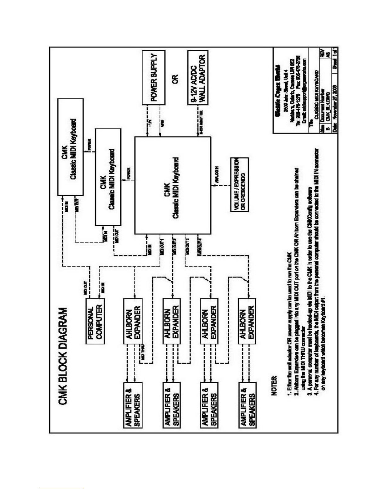
Figure 2: CMK connections
Page-13 October 20, 2004

CLASSIC MIDI KEYBOARD
CMK-1
INSTALLATION
IMPORTANT
READ THIS DOCUMENT BEFORE INSTALLATION
Upon receiving this unit, remove any packing material inside the unit that may have been included to
prevent movement of components or wiring during shipping.
(For internal access, ensure the unit is disconnected from all power sources.)
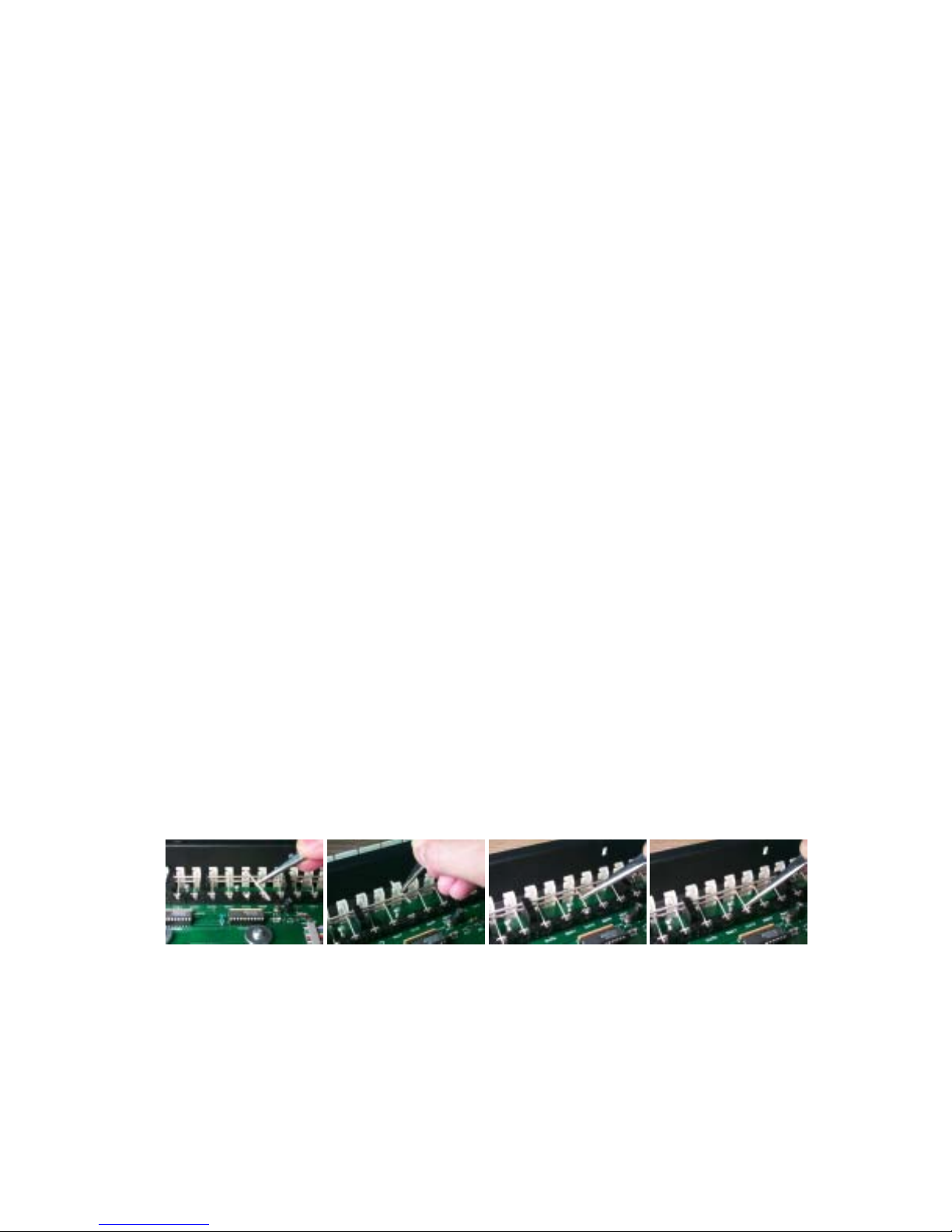
Springs
The keyboard contact springs are installed at Classic Organ Works. However, the nature of these contacts makes them
sensitive to movements during shipping. A visual inspection of the keyboard should be performed upon receiving to
determine if any of these springs have become displaced. A package of five spare springs is included with every
keyboard. To replace the missing springs you will need tweezers and gloves/paper towel. Then follow these
directions:
NOTE: DO NOT HANDLE THE SPRINGS WITH YOUR BARE FINGERS. THE SPRINGS ARE COATED WITH
A LAYER OF SILVER WHICH CAN DETERIORATE IF HANDLED.
1. Pick up the spring using tweezers to gently grip the middle of the spring.
2. Feed one end of the spring in between the two bus bars. Then slide the other end of the spring into the
upper hole (with the keyboard circuit board facing up) of the keyboard keys plastic actuator.
3. With one end of the spring firmly positioned, use the tweezers to grasp the other end of the spring roughly
0.5cm from the end of the spring.
4. SLOWLY stretch this end and position it into the metal spring holder on the circuit board. THE
SPRINGS DEFORM EASILY. USE EXTREME CAUTION TO AVOID OVER-STRETCHING
THE SPRINGS.
1 2 3 4
Mounting
Mounting of the CMK is specific to each customized setup. It can be mounted into a wooden case, into an existing
console, or using metal brackets. In the single keyboard configuration, the CMK is a stand-alone unit. In this
configuration, the keyboard is mounted using metal brackets. However, for a professional finish, an optional wooden
_________________________________________________________________________________________________________
CMK-1 Manual (Issue-1)
Figure 3: Steps in replacing a dislocated spring
Page-15 October 20, 2004
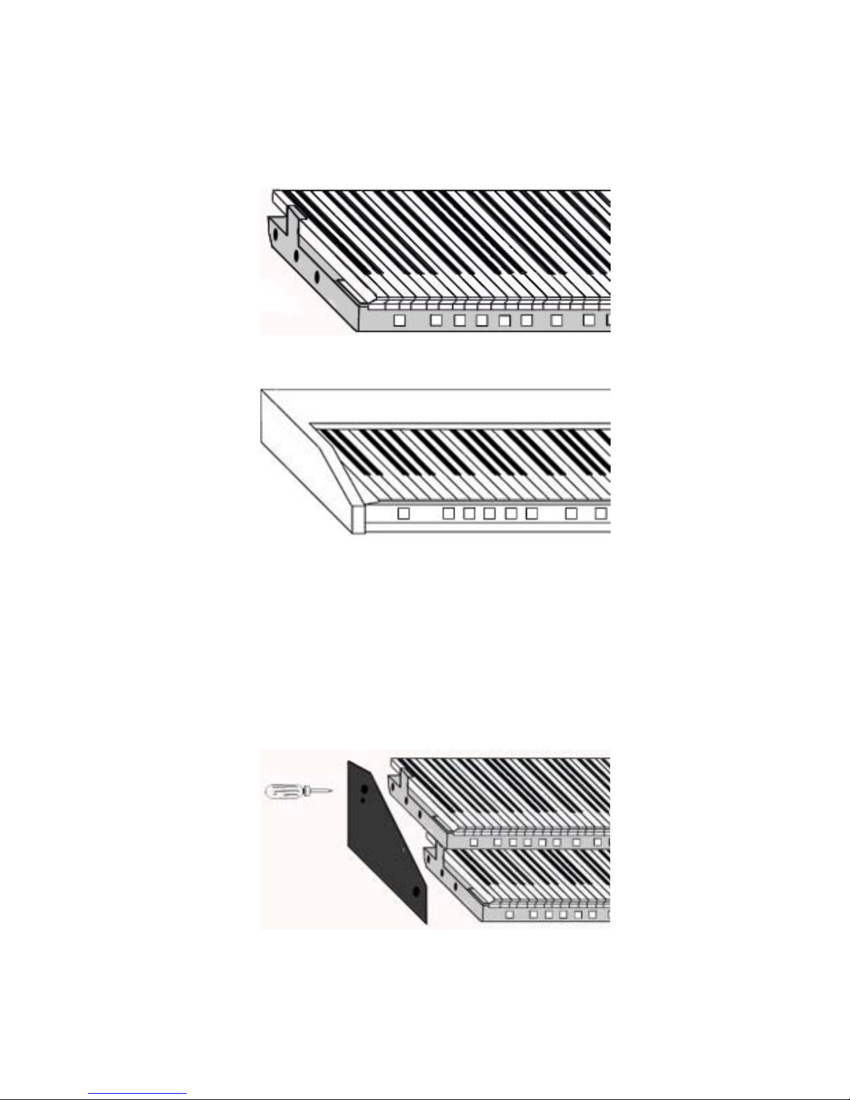
mounting box may be purchased. When mounted in the wooden mounting box, the electronics may be accessed by
removing four screws on the bottom of the wooden case. The CMK keyboard then slides out easily. In both the single
manual and wooden mounting box versions, the CMK is a ready-to-play keyboard requiring only power and MIDI
connections.
Figure 4: Single-manual stand-alone
Figure 5: Single-manual with wooden case
If the CMK is to be mounted into an existing console, the metal pieces at the ends of the keyboard have holes of 0.156
inch diameter to allow the CMK to be fastened to wooden end cheeks using #6 screws.
In the two-keyboard and three keyboard configurations, a separate mounting bracket may be purchased. There are
three threaded holes on the sides of the keyboards for mounting purposes. The holes permit mounting of the keyboards
into the brackets either level or tilted as shown in Figures 8 and 9. The entire two/three keyboard configuration with
mounting brackets may be installed in a console using #6 screws. The electronics are accessible by flipping the
keyboards as shown in Figure 10.
_________________________________________________________________________________________________________
CMK-1 Manual (Issue-1)
Figure 6: Two manual setup
Page-16 October 20, 2004
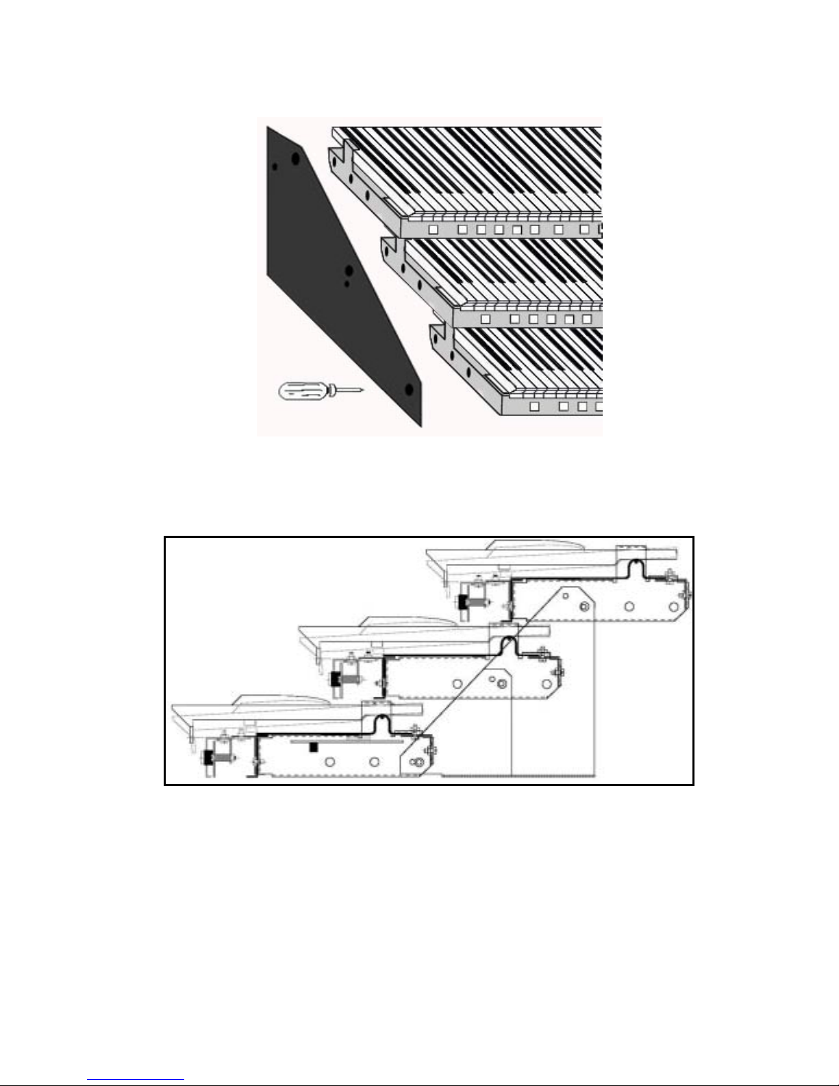
Figure 7: Three manual setup
Figure 8: Two/Three-manual setup mounted level
(Note the pivoting screw positions on each end bracket are different)
_________________________________________________________________________________________________________
CMK-1 Manual (Issue-1)
Page-17 October 20, 2004
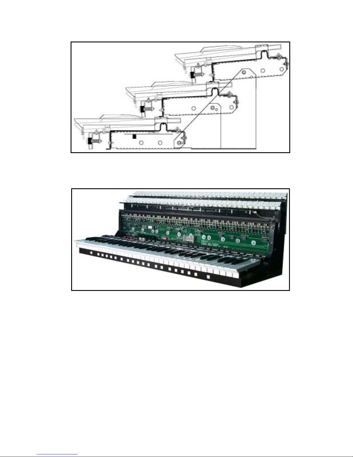
Figure 9: Two/Three-manual setup mounted ‘tilt-up’
Figure 10: Accessing keyboard electronics
Connections
Power
The user must connect Power and MIDI for each keyboard. There are several ways to provide power to the CMK
which will depend on the application. The CMK requires between +9V and +15V DC power at a minimum current of
400mA. If the CMK is to be used as a standalone unit, the most convenient method of providing power would be to
use the supplied 2.1mm Co-axial DC adaptor.
_________________________________________________________________________________________________________
CMK-1 Manual (Issue-1)
Page-18 October 20, 2004
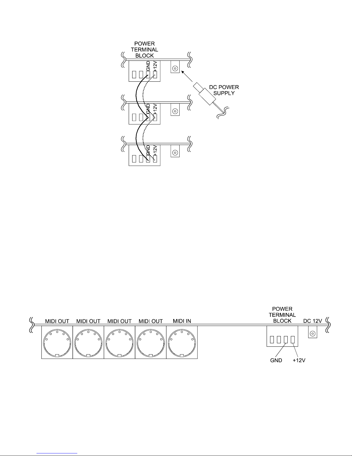
Figure 11: Connecting Multiple CMK Keyboards, Rear View, Using Parallel Wiring and Included Power Supply
However, if multiple keyboards are used or if the CMK is to be mounted inside an organ console, the 4-input terminal
block can be connected to an existing organ power supply. Power and ground are connected to terminal block inputs 1
and 2 respectively. Terminal block inputs 3 and 4 are for grounding the case. One power supply can power up to three
CMK keyboards by paralleling the terminal block connections.
The CMK has a number of safety features. For easy operation, an isolated +12 Volt, DC adaptor of either positive or
negative polarity may be used. It must have a 2.1mm co-axial power jack. A bridge-rectifier is present within the
CMK to ensure the proper polarity. A 500mA self-resetting Polyfuse provides over-current protection from the
common power supply.
MIDI
The CMK has one MIDI input and four paralleled MIDI outputs so that it can be connected to several MIDI devices
and/or a personal computer. All four MIDI OUT connectors produce the same messages and can be used for long
distance applications. The MIDI IN connector allows another MIDI source to be merged with the MIDI signal from
this unit.
The CMK has the capability to simultaneously drive up to four different Ahlborn Archive Series
can be controlled through the general pistons on the CMK. Thus, additional stops and sounds on multiple Ahlborn
Archive modules may be controlled as though they were part of the organ.
_________________________________________________________________________________________________________
CMK-1 Manual (Issue-1)
Figure 12: MIDI Connection Jacks, Rear View
Page-19 October 20, 2004
TM
modules. These
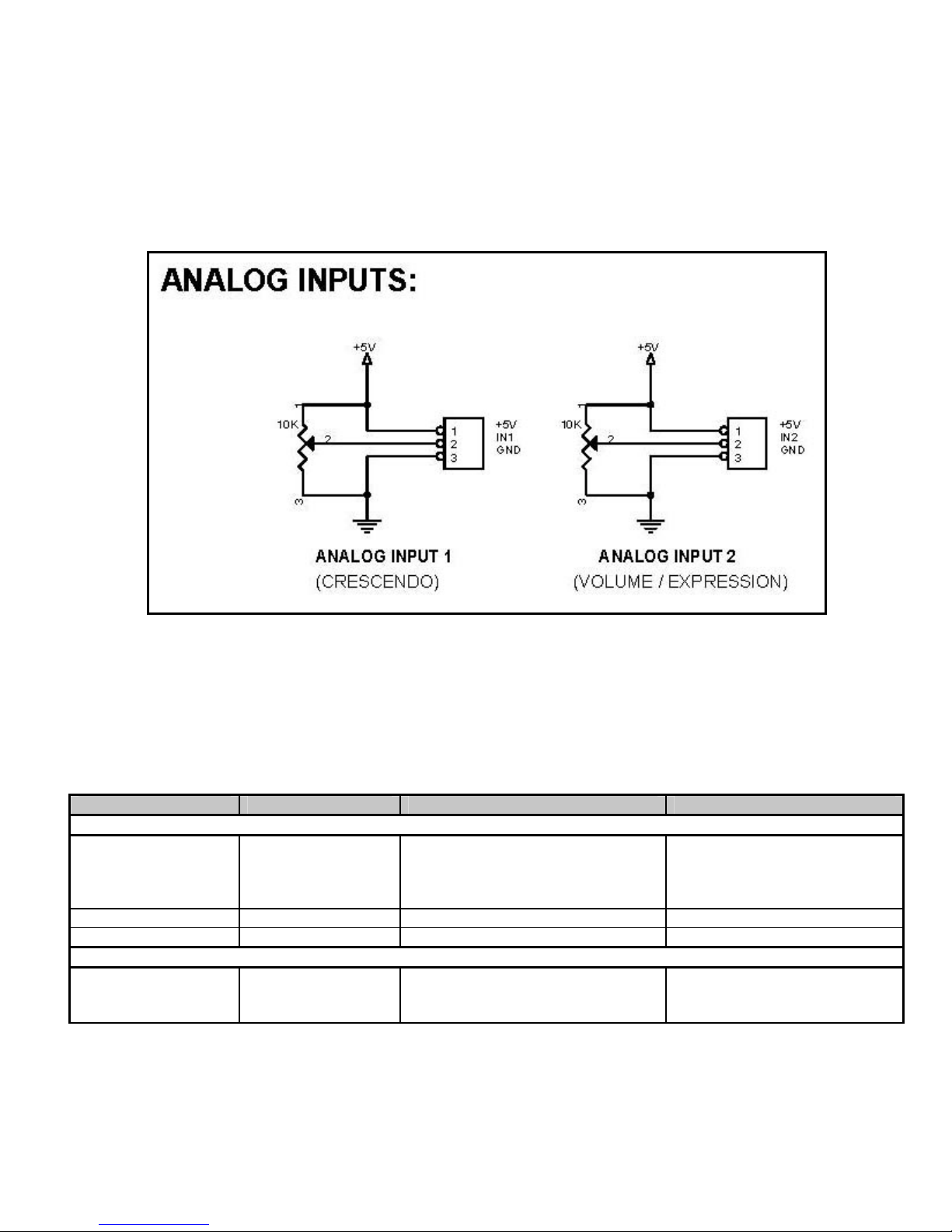
Analog Inputs
Two analog inputs are present on the CMK. The user must ensure that there is one connection to Ground on pin ‘3’,
one connection to an appropriate positive voltage (usually +5V) on pin ‘1’, and one connection to an analog input pin.
Analog inputs are used for crescendo and volume/expression adjustment as shown in Figure 13.
Figure 13: Wiring Schematic for Analog input
The CMK has provision for up to four extra input functions on the circuit board. These inputs are reserved for future
use.
Table 2: Connection Chart
Connection Name Connection Type Hardware Description
Required Connections
Power Input 1. Co-ax 2.1mm (either polarity)
OR
2. 4-input Terminal Block
Input 1 for +12V, Input 2 for GND
MIDI IN Input DIN 5-pin socket 180° Standard MIDI signals
MIDI OUT 1-4 Output DIN 5-pin socket 180° Standard MIDI signals
Optional Connections
Analog Input
Pins, 0.025” Square,
0.3” long, 0.1” pitch
9-12V, 400mA minimum
‘Analog Input 1’ is used for
crescendo and ‘Analog Input 2’ is
used for volume/expression.
_________________________________________________________________________________________________________
CMK-1 Manual (Issue-1)
Page-20 October 20, 2004

Software Installation (Windows1 users only)
Software installation instructions are described in the ‘CMK Configuration Software’ section of the manual.
Note: To use the software, the CMK must be connected to a computer via MIDI. If a MIDI port is not available on
your computer, a commercial MIDI adapter for the game port, USB port, or parallel port may be used.
1
Windows is a registered Trademark of the Microsoft Corporation.
_________________________________________________________________________________________________________
CMK-1 Manual (Issue-1)
Page-21 October 20, 2004

CLASSIC MIDI KEYBOARD
CMK-1
MIDI SPECIFICATION
MIDI (Music Instrument Digital Interface) is a communication system between computer-controlled music
instruments and describes all the actions of a musical performance. It was originally developed for music synthesizers
but, a few years ago, organ-builders began adding MIDI capabilities to pipe organs. However, as MIDI was not
designed for a complex musical instrument such as the organ, its standards are subject to organ-builders preferences.
MIDI is composed of three components which are the language (protocol), hardware (MIDI connector), and
distribution format (MIDI file) [1]. The MIDI language is in binary format and is a uni-directional asynchronous
stream of bits at 31.25 Kbits per second with 10 bits transmitted per byte. The 10 bits per byte consist of a start bit, 8
data bits, and a stop bit. In the hardware domain, the MIDI 1.0 Specification (maintained by the MIDI Manufacturers
Association) recommends the 5-pin DIN 180° connector. The 5-pin DIN connector is standard and allows MIDI
equipment from differing manufacturers to be connected together. MIDI cables transmit information in a unidirectional manner so connectors are designated as either input or output. MIDI files are the standard distribution
format. They capture all the details of MIDI onto a hardcopy medium. MIDI files are similar to the MIDI language
except that they add a time-stamp for each event so that MIDI equipment can replicate the timing required to generate
accurate performances. [1] MIDI Message information can be found in Appendix B and Appendix C.
MIDI Sound Sets
General MIDI [2]
The MIDI Manufacturers Association (MMA) developed General MIDI (GM) to provide a standard relationship
between commands and sounds generated by synthesizers. A serious problem developed as the number of MIDI
device manufacturers grew. Every manufacturer associated different commands with different sounds. Users were
confused when they used a command to play a piano sound but ended up with some other instrument. To alleviate the
confusion, the MIDI Manufacturers Association dictated that commands termed ‘Patch numbers’ would be the
standard reference to a sound. A ‘Patch Map’ shows Patch numbers and their respective sounds. In addition, since
MIDI transmits using MIDI channels, every MIDI sequence begins by assigning a MIDI channel for each sound that is
transmitted. This assignment is termed ‘Program Change’.
In addition to standardizing the mapping of patch numbers to their respective sounds, the General MIDI protocol
defines a set of capabilities for General MIDI instruments. Included are a General MIDI Sound Set (patch map), a
General MIDI Percussion map (maps percussion sounds to note numbers), and a set of General MIDI performance
capabilities (number of voices, MIDI messages recognized, etc.).
MIDI channels 1-9 and 11-16 are used for chromatic instrument sounds, while MIDI channel 10 is used for ‘keybased’ percussion sounds. Furthermore, the 128 program numbers are grouped into 16 related sets. For example,
program numbers 1-8 are for piano sounds, 25-32 are guitar sounds, etc. (a chart is shown on the next page). The pitch
of the sound is indicated by a note number. Note numbers on the ‘key-based’ percussion sounds of MIDI Channel 10
represent different percussion instruments. It should be noted that although sounds may have the same label, they may
_________________________________________________________________________________________________________
CMK-1 Manual (Issue-1)
Page-22 October 20, 2004

not necessarily produce the same sound. The sound output depends on the recorded sound source which is not
standard (an ‘Acoustic Grand Piano’ will sound different depending on the instrument used to produce the sound).
Only the patch numbers and their labels are standardized.
Table 3: Sound Set Groups [3]
Set Sound
1-8 Piano
9-16 Chromatic Percussion
17-24 Organ
25-32 Guitar
33-40 Bass
41-48 Strings
49-56 Ensemble
57-64 Brass
65-72 Reed
73-80 Pipe
81-88 Synthesizer Lead
89-96 Synthesizer Pad
97-104 Synthesizer Effects
105-112 Ethnic
113-120 Percussive
121-128 Sound Effects
_________________________________________________________________________________________________________
CMK-1 Manual (Issue-1)
Page-23 October 20, 2004

Table 4: General MIDI Program Numbers for MIDI Channels 1-9 and 11-16
Patch
Number
1 Acou Grand Piano 44 Contrabass 87 Lead 7 (fifths)
2 Bright Acou Piano 45 Tremolo Strings 88 Lead 8 (bass+lead)
3 Electric Grand Piano 46 Pizzicato Strings 89 Pad 1 (new age)
4 Honky-tonk Piano 47 Orchestral Harp 90 Pad 2 (warm)
5 Electric Piano 1 48 Timpani 91 Pad 3 (polysynth)
6 Electric Piano 2 49 String Ensemble 1 92 Pad 4 (choir)
7 Harpsichord 50 String Ensemble 2 93 Pad 5 (bowed)
8 Clavinet 51 SynthStrings 1 94 Pad 6 (metallic)
9 Celesta 52 SynthStrings 2 95 Pad 7 (halo)
10 Glockenspiel 53 Choir Aahs 96 Pad 8 (sweep)
11 Music Box 54 Voice Oohs 97 FX 1 (train)
12 Vibraphone 55 Synth Voice 98 FX 2 (soundtrack)
13 Marimba 56 Orchestra Hit 99 FX 3 (crystal)
14 Xylophone 57 Trumpet 100 FX 4 (atmosphere)
15 Tubular Bells 58 Trombone 101 FX 5 (brightness)
16 Dulcimer 59 Tuba 102 FX 6 (goblins)
17 Drawbar Organ 60 Muted Trumpet 103 FX 7 (echoes)
18 Percussive Organ 61 French Horn 104 FX 8 (sci-fi)
19 Rock Organ 62 Brass Section 105 Sitar
20 Church Organ 63 Synth Brass 1 106 Banjo
21 Reed Organ 64 Synth Brass 2 107 Shamisen
22 Accordion 65 Soprano Sax 108 Koto
23 Harmonica 66 Alto Sax 109 Kalimba
24 Tango Accordion 67 Tenor Sax 110 Bagpipe
25 Acoustic Guitar (nylon) 68 Baritone Sax 111 Fiddle
26 Acoustic Guitar (steel) 69 Oboe 112 Shanai
27 Electric Guitar (jazz) 70 English Horn 113 Tinkle Bell
28 Electric Guitar (clean) 71 Bassoon 114 Agogo
29 Electric Guitar (muted) 72 Clarinet 115 Steel Drums
30 Overdriven Guitar 73 Piccolo 116 Woodblock
31 Distortion Guitar 74 Flute 117 Tailo Drum
32 Guitar Harmonics 75 Recorder 118 Melodic Drum
33 Acoustic Bass 76 Pan Flute 119 Synth Drum
34 Electric Bass (finger) 77 Blown Bottle 120 Reverse Cymbal
35 Electric Bass (pick) 78 Shakuhachi 121 Guitar Fret Noise
36 Fretless Bass 79 Whistle 122 Breath Noise
37 Slap Bass 1 80 Ocarina 123 Seashore
38 Slap Bass 2 81 Lead 1 (square) 124 Bird Tweet
39 Synth Bass 1 82 Lead 2 (sawtooth) 125 Telephone Ring
40 Synth Bass 2 83 Lead 3 (calliope) 126 Helicopter
41 Violin 84 Lead 4 (chiff) 127 Applause
42 Viola 85 Lead 5 (charang) 128 Gunshot
43 Cello 86 Lead 6 (voice)
Name Patch
Number
Name Patch
[3]
Name
Number
_________________________________________________________________________________________________________
CMK-1 Manual (Issue-1)
Page-24 October 20, 2004
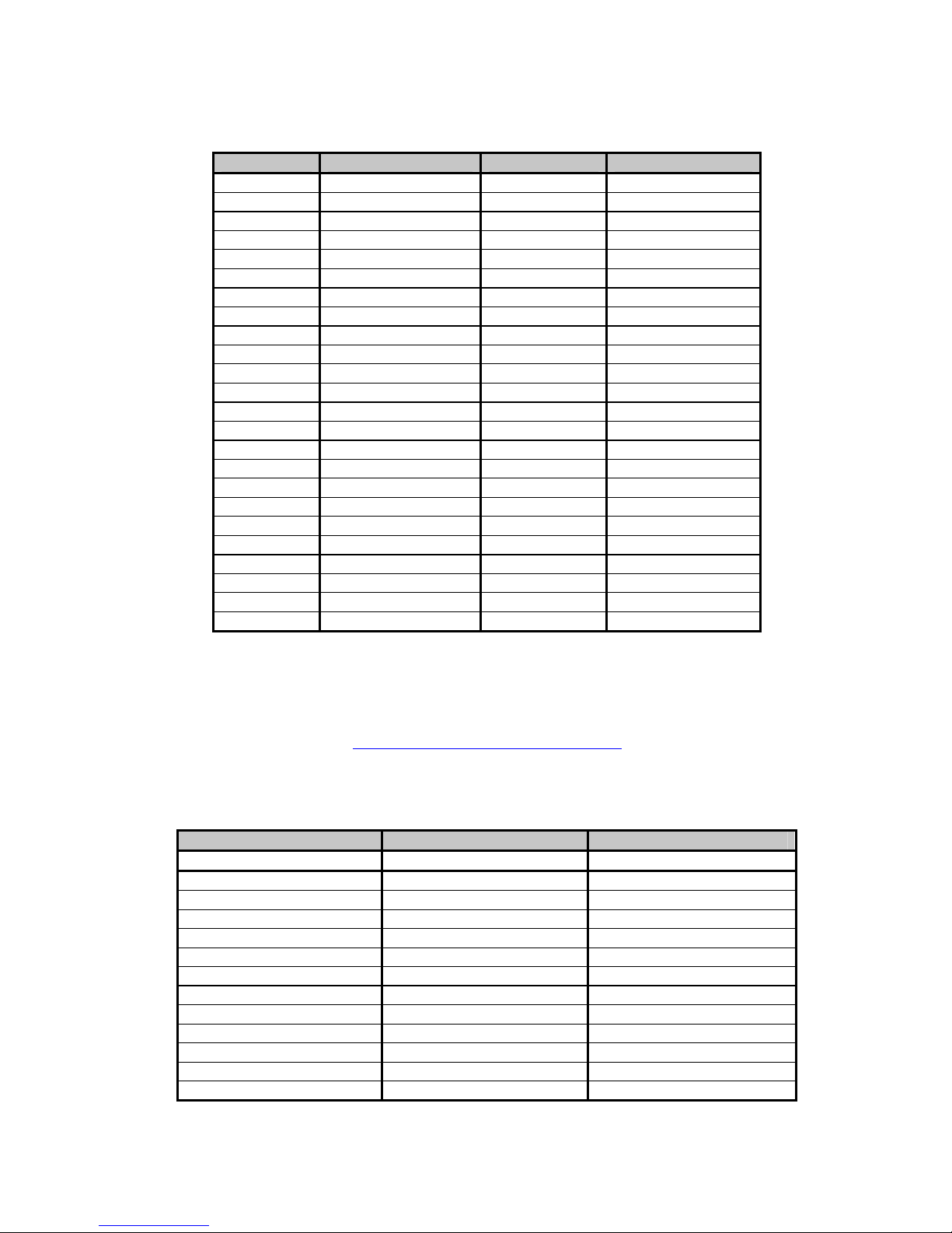
Table 5: General MIDI Percussion Key Map for MIDI Channel 10
MIDI Key Drum Sound MIDI Key Drum Sound
35 Acoustic Bass Drum 59 Ride Cymbal 2
36 Bass Drum 1 60 Hi Bongo
37 Side Stick 61 Low Bongo
38 Acoustic Snare 62 Mute Hi Conga
39 Hand Clap 63 Open Hi Conga
40 Electric Snare 64 Low Conga
41 Low Floor Tom 65 High Timbale
42 Closed Hi-Hat 66 Low Timbale
43 High Floor Tom 67 High Agogo
44 Pedal Hi-Hat 68 Low Agogo
45 Low Tom 69 Cabasa
46 Open Hi-Hat 70 Maracas
47 Low-Mid Tom 71 Short Whistle
48 Hi-Mid Tom 72 Long Whistle
49 Crash Cymbal 1 73 Short Guiro
50 High Tom 74 Long Guiro
51 Ride Cymbal 1 75 Claves
52 Chinese Cymbal 76 Hi Wood Block
53 Ride Bell 77 Low Wood Block
54 Tambourine 78 Mute Cuica
55 Splash Cymbal 79 Open Cuica
56 Cowbell 80 Mute Triangle
57 Crash Cymbal 2 81 Open Triangle
58 Vibraslap
[4]
Ahlborn [5]:
The Ahlborn Archive modules allow additional pipe organ sounds to be played on an existing organ. There are four
separate Ahlborn Archive modules of 20 different stops each over three separate divisions. For more information on
Ahlborn Archive modules, please visit: http://www.ahlbornorgans.com/archive
Archive modules can be found in Appendix D. The stop list for each module is shown below.
Table 6: Classic Module [6]
Division A Division B Pedal
Description Description Description
Gemshorn 8’ Principal 8’ Contre Basse 32’
Gemshorn Celeste 8’ Holzgedackt 8’ Contre Gambe 16’
Flûte à cheminée 8’ Flûte Harmonique 8’ Contre Bombarde 32’
Koppelflöte 4’ Flûte Octaviante 4’ Bombarde 16’
Plein Jeu IV-V Octave 2’ Div. A to Ped.
Bombarde 16’ Cymbale III Div. B to Ped.
Harmonic Trumpet 8’ Tremulant
Corno di Bassetto 8’ Div. A to Div. B
Festival Trumpet 8’
Clarion 4’
Tremulant
Div. B to Div. A
. The messages for controlling Ahlborn
_________________________________________________________________________________________________________
CMK-1 Manual (Issue-1)
Page-25 October 20, 2004
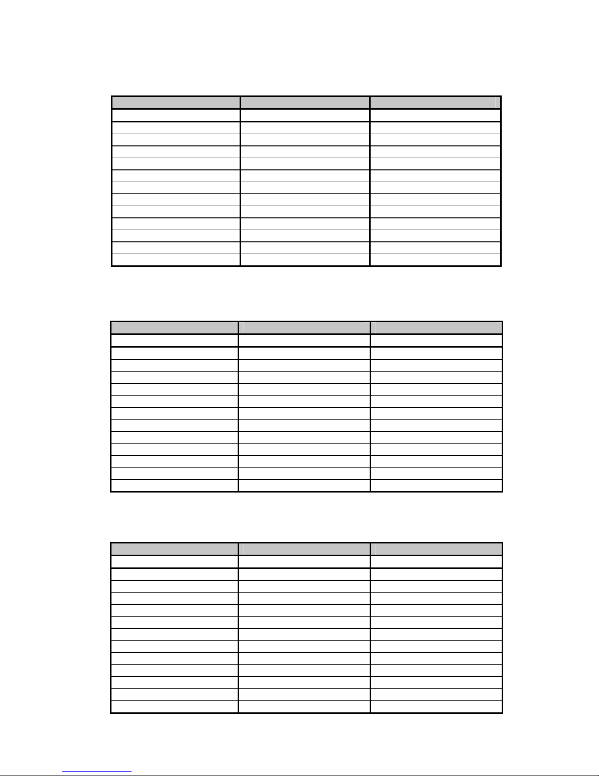
Table 7: Romantic Module
Division A Division B Pedal
Description Description Description
Cello 8’ Open Diapason 8’ Contre Violone 32’
Cello Celeste 8’ Flauto Mirabilis 8’ Contre Gambe 16’
Cornet des Bombardes IV Concert Flute 4’ Contre Bassoon 32’
Cornopean 16’ Quint Flute 2 2/3’ Ophicleide 16’
Clarinet 8’ Piccolo 2’ Div. A to Ped.
Orchestral Oboe 8’ Vox Humana 8’ Div. B to Ped.
French Horn 8’ Tremulant
Cor Anglais 8’ Div. A to Div. B
Tuba Mirabilis 8’
Clarion 4’
Tremulant
Div. B to Div. A
[6]
Table 8: 201 Module [6]
Division A Division B Pedal
Description Description Description
Bourdon 16’ Gedackt 8’ Subbass 16’
Principal 8’ Gamba 8’ Octave 8’
Flûte à cheminée 8’ Nachthorn 4’ Bourdon 8’
Unda Maris 8’ Cymbale III Posaune 16’
Octave 4’ Cornet III Div. A to Ped.
Spitzflöte 2’ Oboe 8’ Div. B to Ped.
Nasard 2 2/3’ Tremulant
Superoctave 2’ Div. A to Div. B
Mixture IV
Trompete 8’
Tremulant
Div. B to Div. A
Table 9: 202 Module
[6]
Division A Division B Pedal
Description Description Description
Contregambe 16’ Bourdon 8’ Soubasse 32’
Diapason 8’ Flûte harmonique 8’ Violone 16’
Quintadena 8’ Flûte octaviante 4’ Contrebombarde 32’
Terz 1 3/5’ Larigot 1 1/3’ Bombarde 16’
Septime 1 1/7’ Corno di bassetto 8’ Div. A to Ped.
Scharff III Clarion 4’ Div. B to Ped.
Bombarde 16’ Tremulant
Trompette 8’ Div. A to Div. B
Tuba Mirabilis 8’
Chimes
Tremulant
Div. B to Div. A
_________________________________________________________________________________________________________
CMK-1 Manual (Issue-1)
Page-26 October 20, 2004
HAUPTWERK
TM
[7]
Hauptwerk (German for ‘Great Organ’) is a computer simulation of a pipe organ. It produces a realistic organ sound
by use of a ‘virtual sampler’ technique. Traditionally, synthesizers used a small number of samples by recording keys
at intervals across the keyboard. In order to simulate all the keys, the samples were time-stretched. Hauptwerk uses a
three-to-five second sample of every pipe in the organ. To accommodate the intensive requirement for memory, a
high-speed personal computer must be used. With current technology, thousands of individual sample sounds can be
stored and recalled when a key is pressed. Thus, the software is able to capture many different and customizable organ
configurations and sounds which can be loaded via ‘.organ’ files. The ‘.organ’ file contains information regarding
number of stops, pistons, and keyboards in addition to other organ-related details.
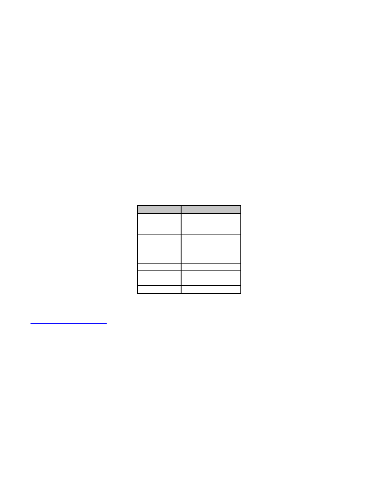
Hauptwerk was initially designed for use with one MIDI keyboard which would be connected to the personal computer
through the sound card game port. If numerous keyboards were required, a MIDI merge box would have to be
purchased. However, the CMK not only performs the MIDI merge function but, also provides an interface for volume
controls, expression controls, and pistons. MIDI messages will then be sent through the MIDI out port to the personal
computer where Hauptwerk software will translate the MIDI message commands into actions on the organ. A table
listing the types of messages sent for the individual functions is shown below.
Table 10: MIDI messages relevant to Hauptwerk
Function MIDI command
Keyboards 1. Note on/off
2. Channel number
3. Key number
Pedalboard 1. Note on/off
2. Channel number
3. Key number
Stops Note on/off
Pistons Program change
Volume Program change
Expression Program change
Crescendo Program change
For more information or to download a shareware version of Hauptwerk software, please visit:
http://www.hauptwerk.co.uk
SCPOP
TM
(not supported on the current version of the CMK)
Sound Canvas Pipe Organ Project (SCPOP) is a computer program that emulates organ features like stop changes,
keyboard coupling, tremolo, assignable memories, temperament changes, and the ability to choose different reverb
settings. All of the features can be accessed using the computer keyboard’s keys like a true organ console. [8]
SCPOP requires a Roland Sound Canvas MIDI Expander module and is only compatible with Roland hardware
containing the ‘Sound Canvas’ label [9]. The messages used to control SCPOP can be found in Appendix E.
_________________________________________________________________________________________________________
CMK-1 Manual (Issue-1)
Page-27 October 20, 2004
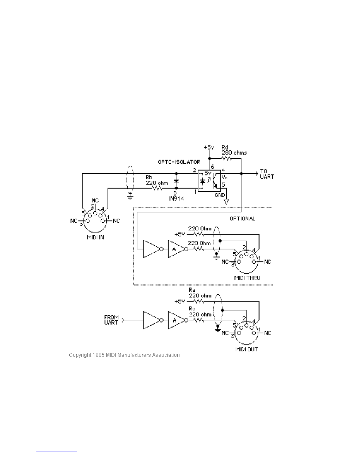
MIDI Hardware Specification [1]
The only MIDI connector approved by the MIDI Manufacturers Association is a 5-pin 180º DIN connector. There are
other ways of connecting devices to send MIDI messages but, it is easier to have compatibility between different MIDI
devices if there is a standard connector. In connecting a MIDI device to a personal computer, the simplest way is
through the MIDI ports of a computer (MIDI connectors are uni-directional from the ‘OUT’ connector to the ‘IN’
connector). Due to space limitations of computer circuit boards, most computers are not equipped with a MIDI port.
Thus, adapters must be used which connect the MIDI device to another port. The most common port is the computer’s
game port which is found on most soundcards. Adapters are also available for the serial port, parallel port, and USB
port.
A schematic of the 5-pin DIN connector typical interface is shown below:
Figure 14: Schematic of 5-pin DIN connector
MIDI Hardware NOTES:
1. Opto-isolator shown is Sharp PC-900. HP 6N138 or other types can be used with changes.
2. Gates "A" are Integrated Circuit or transistor; Resistors are 5%.
3. Maximum cable length is fifty feet (15 meters), terminated at each end by a 5-pin 180º DIN male plug (e.g. SWITCHCRAFT
05GM5M).
4. Cable is shielded twisted-pair, with shield connected to pin 2 at both ends.
_________________________________________________________________________________________________________
CMK-1 Manual (Issue-1)
Page-28 October 20, 2004

CLASSIC MIDI KEYBOARD
CMK-1
CMK HARDWARE CONFIGURATION
Introduction
The CMK is customizable to suit many organ applications. Up to three CMK keyboards may be stacked level or tilted
if the optional mounting brackets are purchased. Each keyboard has 61-keys which serve programming purposes as
well as musical purposes. Two analog inputs are available (for volume/expression and crescendo adjustment).
Power-On Self Test
The CMK has a built-in self test that executes upon power up. This power-on self test serves to detect the presence of
hardware for velocity sensing. The test also checks that all 61 key-switch contacts are functioning properly. If
hardware is not present or is malfunctioning, velocity sensing is automatically disabled. The user can also disable
velocity sensing manually by pressing any keyboard key before connecting power.
Analog Input Pins
There are two analog inputs which can be configured for volume/expression and crescendo. Analog devices must be
connected to the analog input pin, a positive voltage (+5V) on pin ‘1’, and ground potential (0V) on pin ‘3’.
Depending on the position of the analog device, a unique voltage will be read by the processor which will determine
the setting. In the case of a volume control, the position of the analog device will determine the loudness level. See
Figure 13.
MIDI Crescendo
A MIDI program change message is sent to gradually add stops to a registration. ‘Analog Input 1’ is used for
Crescendo.
MIDI Volume
A MIDI program change message is sent to change the loudness level of the stop or sound. The MIDI volume analog
input must be configured to transmit on one or more MIDI channels as outlined in Table 11. ‘Analog input 2’ is used
for Volume but can also be used for Expression.
MIDI Expression
A MIDI program change message is sent to set the loudness level within the preset volume range. ‘Analog Input 2’ is
used for Expression but can also be used for Volume. Expression messages adjust the loudness within a range not
exceeding the maximum set by volume. The MIDI Expression analog input must be configured to transmit on one or
more MIDI channels as outlined in Table 11. In multi-manual CMK setups, the range for the Expression control can
be set by attaching a Volume control to one of the keyboards and attaching an Expression control to another keyboard.
_________________________________________________________________________________________________________
CMK-1 Manual (Issue-1)
Page-29 October 20, 2004

If the volume and expression controls are set to produce messages on the same MIDI channels, the volume control will
set the maximum range while the expression control will change the loudness level in the volume range.
Programming
The following chart lists different functions achievable using the piston pushbuttons and keyboard key-switches.
Table 11: Piston programming functions
Name Steps Function
SOFT
REBOOT
SET MIDI
CHANNELS
FOR THE
KEYBOARD
CLEAR MIDI
CHANNELS
FOR THE
KEYBOARD
Press the 1st piston
from the left (SET)
st
and 1
piston from
the right
(CANCEL)
simultaneously
Hold the 1st piston
from the left (SET)
and the 1
st
black
key from the left
(C#1). Then select
any combination of
the 1
st
16 white
keys from the left
(C1 to D3).
Afterwards, release
the SET piston.
Hold 1st piston from
the left (SET) and
nd
2
black key from
the left (D#1).
Afterwards, release
the SET piston.
Performs a soft reboot. This will restart the keyboard
and reload configuration data from the on-board
EEPROM.
Sets the output MIDI channels for the keyboard. For
example, if we configure the keyboard to output on
channels 1, 3 and 5, then all MIDI events originating
from that keyboard will produce MIDI messages
transmitted on these three channels.
Clears the output MIDI channels for the keyboard.
DEFAULT
VELOCITY
(if keyboard is
in non-velocity
mode)
Hold the 1st piston
from the left (SET)
rd
and 3
from the left (F#1).
Then press one of
the white keys and
release the SET
piston.
_________________________________________________________________________________________________________
CMK-1 Manual (Issue-1)
black key
If the keyboard is set to non-velocity mode, the
default velocity output of the keyboard can be
selected. This is accomplished by using the white
keys select a velocity level between 0 (bass end:
softest) and 127 (treble end: loudest). Keys pressed
in between will produce a velocity level between 0
and 127 depending on the location of the key
relative to the extremes. The change in velocity level
between adjacent white keys is approximately 3.
Note that in the event multiple keys are pressed,
only the last one released will be registered by the
software.
Page-30 October 20, 2004

Table 11: Piston programming functions (cont’d)
Name Steps Function
VELOCITY
SENSING
ON/OFF
ANALOG
INPUT –
VOLUME
SETUP
DISABLING
ANALOG
INPUT –
VOLUME
Hold 1st piston from
the left (SET) and 4
black key from the
left (G#1) to turn off
velocity sensing.
st
Hold 1
piston (SET)
th
and 5
black key
from the left (A#1) to
turn on velocity
sensing. Afterwards,
release the SET
piston.
Hold the 1st piston
from the left (SET)
and the 6
th
black key
from the left (C#2).
Then select any
combination of the 1
16 white keys from
the left (C1 to D3).
Afterwards, release
the SET piston.
Hold the 1st piston
from the left (SET)
and the 6
th
black key
from the left (C#2).
Afterwards, release
the SET piston.
th
Velocity sensing produces a different volume level
corresponding to the force with which a key is pressed.
To conform to traditional organ consoles which are not
velocity sensitive, the CMK permits users to disable
velocity sensing in the keyboard.
Sets the output MIDI channels for the volume analog
input. For example, if we configure the analog input to
produce General MIDI volume information on channels
1, 3 and 5, then all MIDI events originating from that
analog input will produce MIDI messages transmitted on
st
these three channels. Please note that the crescendo input
does not require setup because it produces messages for
the Ahlborn Archive modules.
MIDI messages describing volume information from the
analog input will not be transmitted on any MIDI
channel.
ANALOG
INPUT –
EXPRESSION
SETUP
Hold the 1st piston
from the left (SET)
and the 7
th
black key
from the left (D#2).
Then select any
combination of the 1
16 white keys from
the left (C1 to D3).
Sets the output MIDI channels for the expression analog
input. For example, if we configure the analog input to
produce General MIDI expression information on
channels 1, 3 and 5, then all MIDI events originating
from that analog input will produce MIDI messages
st
transmitted on these three channels. Please note that the
crescendo input does not require setup because it
produces messages for the Ahlborn Archive modules.
Afterwards, release
the SET piston.
DISABLING
ANALOG
INPUT -
EXPRESSION
Hold the 1st piston
from the left (SET)
and the 7
th
black key
from the left (D#2).
Afterwards, release
MIDI messages describing expression information from
the analog input will not be transmitted on any MIDI
channel.
the SET piston.
_________________________________________________________________________________________________________
CMK-1 Manual (Issue-1)
Page-31 October 20, 2004

CLASSIC MIDI KEYBOARD
CMK-1
CMK SOFTWARE CONFIGURATION
(PC WindowsTM USERS ONLY)
Introduction
Users with access to a personal computer running Windows
(contained in the compact disc) to program additional configurations. These configuration files describe the features
of each keyboard such as output MIDI channel and the function of each piston. The software allows users to create
configuration files, change existing configuration files, and use existing configuration files.
TM 1
operating system can use the ‘CMKConfig’ software
Software Installation
The CMK includes a compact disc (CD) with software allowing users to create custom configurations. To use the
software, the CMK must be connected to a personal computer running Windows operating system software
(Windows 98, 2000, XP). The CMK must be connected to a computer using MIDI. If a MIDI port is not available
on your computer, commercial MIDI adapters for the game port, USB port, and parallel port may be used. When the
installation CD is placed in the optical drive of your computer (CD drive), the software installation wizard should
automatically run. If however, the software installation wizard does not automatically run follow the steps below:
1. Open the ‘Start’ menu and click on ‘Run’.
2. Click on ‘Browse’ and select the optical drive (CD drive) from the ‘Look in:’ drop down menu.
3. Locate and click on a file named ‘CMK_Setup.exe’.
4. Follow the instructions in the software installation wizard (screen captures are shown below).
1
Windows is a registered Trademark of the Microsoft Corporation.
_________________________________________________________________________________________________________
CMK-1 Manual (Issue-1)
Page-32 October 20, 2004

Figure 15: Upon clicking on the ‘CMK_Setup.exe’ file, the above window will appear.
Figure 16: Allows the user to select a directory to install the CMK program file
_________________________________________________________________________________________________________
CMK-1 Manual (Issue-1)
Page-33 October 20, 2004

Figure 17: Setup adds an icon to the start menu for convenient access
Figure 18: Setup provides the option of creating an icon on the Windows desktop
_________________________________________________________________________________________________________
CMK-1 Manual (Issue-1)
Page-34 October 20, 2004

Figure 19: Confirmation window
_________________________________________________________________________________________________________
CMK-1 Manual (Issue-1)
Figure 20: Setup progress window
Page-35 October 20, 2004

Figure 21: Confirms installation was successful
_________________________________________________________________________________________________________
CMK-1 Manual (Issue-1)
Page-36 October 20, 2004

Software Startup
After installation, a shortcut titled ‘CMKConfig’ will be created in the ‘Classic Organ Works’ folder (Start menu→
Programs→ Classic Organ Works→ CMKConfig). To start using the software, click your left mouse button on this
‘CMKConfig’ shortcut. You should see a screen as shown below:
Figure 22: CMKConfig software startup screen.
Press a key on your computer keyboard or click on any mouse button and the main menu selection will appear:
The main menu allows you to select one of two editing types:
1. Configure a Classic MIDI Keyboard from scratch: This mode allows you to create a new file for storing on
the CMK memory or for generating a file on your PC.
2. Load a previously saved CMK configuration: This mode allows you to edit a file stored on your PC.
_________________________________________________________________________________________________________
CMK-1 Manual (Issue-1)
Figure 23: CMKConfig software main menu.
Page-37 October 20, 2004

Configure a CMK from scratch
This editing mode allows the user to create a new configuration for the CMK. The user can then choose to save the
new settings on a computer or transfer the file to the CMK memory as a new configuration. When a user selects the
‘Configure a Classic CMK from scratch’ option from the main menu, the software attempts to make a connection to
the CMK as shown below. Note: If this is the first time you run CMKConfig, the software will prompt the user for the
computer’s MIDI configuration. See ‘MIDI I/O Setup’ on page 45.
Figure 24: CMKConfig software attempting to connect with the CMK
If a connection is not made, the following window appears:
Figure 25: CMKConfig software unable to connect
If a connection is made, the CMKConfig software will indicate the number of keyboards connected.
Figure 26: CMKConfig software successfully connected to the CMK.
_________________________________________________________________________________________________________
CMK-1 Manual (Issue-1)
Page-38 October 20, 2004

Afterwards, the following window appears. The software defaults to reading the DIP switch. However, the user can
specify another configuration number for the new configuration.
Figure 27: Successful connection between CMKConfig software and CMK.
When the user has specified the configuration number, CMKConfig software will load data from the CMK to start the
configuration process.
Figure 28: Window confirms the loading of pre-configuration data from the CMK to the PC.
The user can then design a custom configuration to the required specification.
_________________________________________________________________________________________________________
CMK-1 Manual (Issue-1)
Page-39 October 20, 2004

Load a previously saved CMK configuration
CMK configuration files are saved on a PC in the format: filename.cmk. In this editing type, a configuration file that
exists on your computer may be edited to the new specifications. The user can then choose to save the new settings on
a computer or transfer the file to the CMK memory as a new configuration. When a user selects the ‘Load a
previously saved CMK configuration’ option from the main menu, the software prompts for a filename through the
following window:
Figure 29: Configuration File selection window.
After selecting the appropriate file, click on the ‘Open’ button. A window should appear like the one shown below:
Figure 30: Program window
At this point, the user may customize each of the drop-down menus to their specifications.
_________________________________________________________________________________________________________
CMK-1 Manual (Issue-1)
Page-40 October 20, 2004

Functions of the Toolbars
The software has toolbars which contain four main functions:
Figure 31: Toolbars in CMKConfig software
1. File Menu
• Open Program Data File – Loads a configuration file (with a ‘.cmk’ extension) from the PC to the
CMKConfig software. The user may then edit the file to their specifications.
Icon:
Keyboard shortcut: Ctrl+O
To begin loading a configuration go to File → Open Program Data File, or use the Keyboard shortcut,
or icon shown above. A window prompting the user for a filename should appear:
Figure 32: Loading Program Data From File Window
The user can then select the filename and click on the ‘O
• Save Program Data File – Saves a configuration file to be stored on the PC. All configuration files
have a ‘.cmk’ extension.
Icon:
Keyboard shortcut: Ctrl+S
To save a configuration file to the PC, go to File → Save Program Data File, or use the Keyboard
shortcut or icon shown above.
_________________________________________________________________________________________________________
CMK-1 Manual (Issue-1)
pen’ button.
Page-41 October 20, 2004

A window prompting the user for a filename should appear:
Figure 33: Save Program Data to File Window
If the configuration uses the same name as a previous configuration, a warning window will ask the
user for confirmation in replacing the old file with the newly revised one.
Icon:
Figure 34: Confirm replacing of file window
• Load Program Data From CMK – Loads a configuration file from the CMK memory chip. A CMK
may contain numerous configuration files which are selectable by changing the DIP-switch so, the
software displays an initial configuration number as set in the DIP-switch. If a configuration number
different from the DIP switch is required, it may be specified by the user.
Keyboard shortcut: Ctrl+L
To load a configuration from the CMK memory chip, the user must ensure that the CMK is connected
to power and to a computer using a MIDI cable (please see software installation for details on
connecting MIDI devices to computers). Then go to File → Load Program Data From CMK, or use
the keyboard shortcut or icon as shown above. A window appears attempting to make a connection
with the CMK as shown in Figure 35.
_________________________________________________________________________________________________________
CMK-1 Manual (Issue-1)
Page-42 October 20, 2004

Figure 35: Software attempting to make a connection with the CMK
If a connection is not available, a window will appear as a reminder to make connections to the CMK:
Figure 36: Software unable to make a connection with the CMK
If a connection is made, a window will appear to confirm the communication.
Figure 37: Software detecting number of keyboards
_________________________________________________________________________________________________________
CMK-1 Manual (Issue-1)
Page-43 October 20, 2004

A window will then appear and the program will read the DIP switch to get the configuration number
(see table 12 in Appendix A for DIP switch codes). The user may change the configuration number to
be loaded if desired.
Figure 38: Successful connection between CMK and PC software
After the user has the desired configuration number, pressing ‘OK’ will display a window to confirm
the selection:
Icon:
Figure 39: Confirms loading of configuration into CMKConfig software.
• Write Program Data to CMK – Saves a configuration file to the CMK memory chip. Typical CMK
units will have numerous configuration files so the user should specify the configuration number of
the current file.
Keyboard shortcut: Ctrl+W
To save a configuration to the CMK, go to File → Write Program Data to CMK or, use the keyboard
shortcut or icon as shown above. The Software attempts to make a connection to the CMK.
Figure 40: Software attempting to communicate with CMK
_________________________________________________________________________________________________________
CMK-1 Manual (Issue-1)
Page-44 October 20, 2004

Figure 41: Successful Software connection to the CMK
NOTE: The ‘DIP Switch is set to’ field reflects the current DIP Switch setting. Care must be taken
when choosing a new ‘Configuration Number’. If a ‘Configuration Number’ already contains settings,
writing to the same ‘Configuration Number’ will overwrite this information.
A window should appear to confirm that the contents were written.
2. Options Menu
• MIDI I/O Setup – This function sets the MIDI input and output ports on your PC.
Icon:
Keyboard shortcut: Ctrl+M
Figure 42: Confirms configuration written to CMK from CMKConfig software.
_________________________________________________________________________________________________________
CMK-1 Manual (Issue-1)
Figure 43: MIDI Input Output Setup window
Page-45 October 20, 2004

2. Help Menu
• View CMKConfig Documentation – This function displays the CMK documentation in a web
• About CMKConfig – This function contains the software title, company and version number.
browser.
Figure 44: Help Menu
Keyboard Functions
The keyboard is a physical representation of the items that a user needs to specify when configuring the CMK. The
user must specify functions for two categories: ‘MIDI channel output’ and ‘Piston function’.
• MIDI Channel output - This function controls the MIDI Channel(s) on which the keyboard can send
messages. To specify the MIDI channel(s), click on the keys of the keyboard and a menu such as the
one shown on the next page will appear. To select the MIDI Channel(s), use the mouse cursor to point
and click on the numbered buttons inside the blue bubble. These numbers correspond to the MIDI
Channels from 1-16 since the keyboard can send on multiple channels. Clicking on a selected
numbered button again will deselect it.
_________________________________________________________________________________________________________
CMK-1 Manual (Issue-1)
Page-46 October 20, 2004

Figure 45: Clicking on the keys of the keyboard invokes a MIDI Channel select menu.
• Piston Function – Each piston can be configured for a particular function. To select these functions
from a menu, click on any one of the twenty piston buttons and navigate through the resulting dropdown menus.
Figure 46: Clicking on an individual piston invokes the Piston function select drop-down menu.
_________________________________________________________________________________________________________
CMK-1 Manual (Issue-1)
Page-47 October 20, 2004

Note that configuring these pistons in software does not affect the use of the two end buttons to set keyboard hardware
parameters as discussed on page 29.
Three drop-down menus enable the user to select the MIDI device being controlled, specific functions of these devices,
and the MIDI output channel for the command.
Table 12: Customizable Functions for each piston
Ahlborn Coupler: Allows a keyboard to play stops from another division
A to Pedal B to Pedal B to A A to B A to Aux B to Aux
Ahlborn Tremulant
Swell Tremulant Great Tremulant Choir Tremulant
Ahlborn Cancel
General Cancel Swell
Divisional Cancel
Great
Divisional Cancel
Choir
Divisional Cancel
Ahlborn General: associates a combination of stops to a memory level.
These combinations can be from different divisions.
Memory A
General #1
Memory B
General #1
Memory C
General #1
Memory D
General #1
Memory E
General #1
Memory A
General #2
Memory B
General #2
Memory C
General #2
Memory D
General #2
Memory E
General #2
Memory A
General #3
Memory B
General #3
Memory C
General #3
Memory D
General #3
Memory E
General #3
Memory A
General #4
Memory B
General #4
Memory C
General #4
Memory D
General #4
Memory E
General #4
Memory A
General #5
Memory B
General #5
Memory C
General #5
Memory D
General #5
Memory E
General #5
Memory A
General #6
Memory B
General #6
Memory C
General #6
Memory D
General #6
Memory E
General #6
Ahlborn SET: confirms assignment of stops to a piston
Ahlborn SFZ: activates all stops of the organ
Hauptwerk/Program Change: Allows users to control Hauptwerk functions or send program change
commands using the pistons
Any Program Change number from 1 to 128
_________________________________________________________________________________________________________
CMK-1 Manual (Issue-1)
Page-48 October 20, 2004

Table 12: Customizable Functions for each piston (cont’d)
SCPOP function: Allows user to control SCPOP functions
Left Up Center Down Right Clear
Great Flues Swell Flues Great Mixture Great Reeds Swell Reeds Pedal Stops
Great to Swell Great to Pedal Swell to Great Swell to Pedal Tremolo Swell Tremolo Great
Panic Rec Thru Reset Cancel
Free
Memory # 1
Free
Memory # 6
Fixed
Memory # 1
Fixed
Memory # 7
Go Flues Mute Sw Flues Mute Go Reeds
Free
Memory # 2
Free
Memory # 7
Fixed
Memory # 2
Fixed
Memory # 8
Free
Memory # 3
Free
Memory # 8
Fixed
Memory # 3
Fixed
Memory # 9
Free
Free Memory # 5
Memory # 4
Free
Free Memory #10
Memory # 9
Fixed
Memory # 4
Fixed
Memory # 10
Fixed Memory # 5 Fixed
Fixed
Memory # 11
Sw Reeds Mute Unused
Memory # 6
Fixed
Memory # 12
Mute
Temper
Type –
Temper
Type +
Temper
Key –
Temper
Key +
Reverb
Configuring Multiple Keyboards
The software supports the two-manual and three-manual CMK setups. For multi-manual setups, the software screen
will show multiple keyboards rather than a single keyboard. In the single keyboard setup, the keyboard is labeled
‘Manual #1’ in the CMKconfig program window. However, for a multi-manual setup, the keyboards are numbered
according to their place in the daisy-chain. Therefore, the keyboard labeled ‘Manual #1’ represents the keyboard
connected directly to the MIDI OUT port of the personal computer. ‘Manual #2’ would be connected to the MIDI
OUT port of ‘Manual #1’ and so forth. The final keyboard in the chain will have one MIDI OUT port connected to the
MIDI IN port from the personal computer. The final keyboard also connects to any Ahlborn Archive and General
MIDI sound modules. Using the software for setup of multiple keyboards is exactly the same as for the single-manual.
For more details on correct installation, please see Figure 2 in the ‘Introduction’ section.
_________________________________________________________________________________________________________
CMK-1 Manual (Issue-1)
Page-49 October 20, 2004


MIDI CONTROL UNIT
CMK-1
REFERENCES
[1] “What is MIDI” [Online Document], 1995, [cited 2002 December 12], Available HTTP:
http://www.midi.org/about-midi/abtmidi.htm
[2] “Tutorial on MIDI and Music Synthesis” [Online Document], 1995, [cited 2002 December 12], Available
HTTP: http://www.midi.org/about-midi/tutorial/tutor.htm
[3] “General MIDI Patch Map” [Online Document], [cited 2002 December 16], Available HTTP:
http://www.people.virginia.edu/~pdr4h/gmpatch.html
[4] “General MIDI Standards, Table 2 – General MIDI Percussion Key Map” [Online Document], 1998 August 9,
[cited 2002 December 16], Available HTTP: http://midistudio.com/Help/GMSpecs_PercMap.htm
[5] “Archive Technical Specifications” [Online Document], 2002, [cited 2002 December 17], Available HTTP:
http://www.ahlborn-galanti.com/archive/techspec.html
[6] “Archive Stops” [Online Document], 2002, [cited 2002 December 17], Available HTTP:
http://www.ahlborn-galanti.com/archive/stops.html
[7] “Hauptwerk: a Virtual Pipe Organ Project” [Online Document], 2003, [cited 2003 January 6], Available
HTTP: http://www.hauptwerk.co.uk
[8] “What is SCPOP?” [Online Document], 2002 December, [cited 2002 December 17], Available HTTP:
http://www.chsinet.via.t-online.de/Project_all.htm
[9] Filippo Tigli, “Frequently Asked Questions” [Online Document], 2002 October, [cited 2003 January 7],
Available HTTP: http://www.chsinet.via.t-online.de/faq.htm
[10] “Summary of MIDI Messages” [Online Document], 1995, [cited 2002 December 12],
Available HTTP: http://www.midi.org/about-midi/table1.htm
[11] “Expanded Status Bytes List” [Online Document], 1995, [cited 2002 December 12],
Available Http: http://www.midi.org/about-midi/table2.htm
[12] “Summary of Control Change Messages (Data Bytes)” [Online Document], 1995, [cited 2002 December 12],
Available HTTP: http://www.midi.org/about-midi/table3.htm
[13] R. Sung, System Exclusive Message layouts
[14] H. Wemekamp, Classic MIDI Keyboard Interface System Software, Classic Organ Works, Markham, Canada:
2002
[15] B. Tubb, “General MIDI Pipe Organ Emulation” [Online Document], 1998, [cited 2002 December 12],
Available by contacting author at: brtubb@cybertron.com
_________________________________________________________________________________________________________
CMK-1 Manual (Issue-1)
, Classic Organ Works, Markham, Canada: 2002
Page-51 October 20, 2004

_________________________________________________________________________________________________________
CMK-1 Manual (Issue-1)
Page-52 October 20, 2004

CLASSIC MIDI KEYBOARD
DIP SWITCH CONFIGURATION TABLE
Table 13: DIP Switch settings and their corresponding Configuration numbers
Configuration
Number
1
2
3
4
5
6
7
8
9
10
11
12
13
14
15
16
17
18
19
20
21
22
23
24
25
26
27
28
29
30
31
32
33
34
35
36
Note: DIP-Switch settings: Off = 0, On = 1
Switch 1 Switch 2 Switch 3 Switch 4 Switch 5 Switch 6 Switch 7 Switch
0 0 0 0 0 0 0 0
1 0 0 0 0 0 0 0
0 1 0 0 0 0 0 0
1 1 0 0 0 0 0 0
0 0 1 0 0 0 0 0
1 0 1 0 0 0 0 0
0 1 1 0 0 0 0 0
1 1 1 0 0 0 0 0
0 0 0 1 0 0 0 0
1 0 0 1 0 0 0 0
0 1 0 1 0 0 0 0
1 1 0 1 0 0 0 0
0 0 1 1 0 0 0 0
1 0 1 1 0 0 0 0
0 1 1 1 0 0 0 0
1 1 1 1 0 0 0 0
0 0 0 0 1 0 0 0
1 0 0 0 1 0 0 0
0 1 0 0 1 0 0 0
1 1 0 0 1 0 0 0
0 0 1 0 1 0 0 0
1 0 1 0 1 0 0 0
0 1 1 0 1 0 0 0
1 1 1 0 1 0 0 0
0 0 0 1 1 0 0 0
1 0 0 1 1 0 0 0
0 1 0 1 1 0 0 0
1 1 0 1 1 0 0 0
0 0 1 1 1 0 0 0
1 0 1 1 1 0 0 0
0 1 1 1 1 0 0 0
1 1 1 1 1 0 0 0
0 0 0 0 0 1 0 0
1 0 0 0 0 1 0 0
0 1 0 0 0 1 0 0
1 1 0 0 0 1 0 0
CMK-1
APPENDIX A:
8
_________________________________________________________________________________________________________
CMK-1 Manual (Issue-1)
Page-53 October 20, 2004

Table 13: DIP Switch settings and their corresponding Configuration numbers (cont’d)
Configuration
Switch 1 Switch 2 Switch 3 Switch 4 Switch 5 Switch 6 Switch 7 Switch
Number
37
38
39
40
41
42
43
44
45
46
47
48
49
50
51
52
53
54
55
56
57
58
59
60
61
62
63
64
65
66
67
68
69
70
71
72
73
74
75
76
77
78
79
80
81
82
83
84
85
86
87
88
0 0 1 0 0 1 0 0
1 0 1 0 0 1 0 0
0 1 1 0 0 1 0 0
1 1 1 0 0 1 0 0
0 0 0 1 0 1 0 0
1 0 0 1 0 1 0 0
0 1 0 1 0 1 0 0
1 1 0 1 0 1 0 0
0 0 1 1 0 1 0 0
1 0 1 1 0 1 0 0
0 1 1 1 0 1 0 0
1 1 1 1 0 1 0 0
0 0 0 0 1 1 0 0
1 0 0 0 1 1 0 0
0 1 0 0 1 1 0 0
1 1 0 0 1 1 0 0
0 0 1 0 1 1 0 0
1 0 1 0 1 1 0 0
0 1 1 0 1 1 0 0
1 1 1 0 1 1 0 0
0 0 0 1 1 1 0 0
1 0 0 1 1 1 0 0
0 1 0 1 1 1 0 0
1 1 0 1 1 1 0 0
0 0 1 1 1 1 0 0
1 0 1 1 1 1 0 0
0 1 1 1 1 1 0 0
1 1 1 1 1 1 0 0
0 0 0 0 0 0 1 0
1 0 0 0 0 0 1 0
0 1 0 0 0 0 1 0
1 1 0 0 0 0 1 0
0 0 1 0 0 0 1 0
1 0 1 0 0 0 1 0
0 1 1 0 0 0 1 0
1 1 1 0 0 0 1 0
0 0 0 1 0 0 1 0
1 0 0 1 0 0 1 0
0 1 0 1 0 0 1 0
1 1 0 1 0 0 1 0
0 0 1 1 0 0 1 0
1 0 1 1 0 0 1 0
0 1 1 1 0 0 1 0
1 1 1 1 0 0 1 0
0 0 0 0 1 0 1 0
1 0 0 0 1 0 1 0
0 1 0 0 1 0 1 0
1 1 0 0 1 0 1 0
0 0 1 0 1 0 1 0
1 0 1 0 1 0 1 0
0 1 1 0 1 0 1 0
1 1 1 0 1 0 1 0
Note: DIP-Switch settings: Off = 0, On = 1
8
_________________________________________________________________________________________________________
CMK-1 Manual (Issue-1)
Page-54 October 20, 2004

Table 13: DIP Switch settings and their corresponding Configuration numbers (cont’d)
Configuration
Number
89
90
91
92
93
94
95
96
97
98
99
100
101
102
103
104
105
106
107
108
109
110
111
112
113
114
115
116
117
118
119
120
121
122
123
124
125
126
127
128
Switch 1 Switch 2 Switch 3 Switch 4 Switch 5 Switch 6 Switch 7 Switch
8
0 0 0 1 1 0 1 0
1 0 0 1 1 0 1 0
0 1 0 1 1 0 1 0
1 1 0 1 1 0 1 0
0 0 1 1 1 0 1 0
1 0 1 1 1 0 1 0
0 1 1 1 1 0 1 0
1 1 1 1 1 0 1 0
0 0 0 0 0 1 1 0
1 0 0 0 0 1 1 0
0 1 0 0 0 1 1 0
1 1 0 0 0 1 1 0
0 0 1 0 0 1 1 0
1 0 1 0 0 1 1 0
0 1 1 0 0 1 1 0
1 1 1 0 0 1 1 0
0 0 0 1 0 1 1 0
1 0 0 1 0 1 1 0
0 1 0 1 0 1 1 0
1 1 0 1 0 1 1 0
0 0 1 1 0 1 1 0
1 0 1 1 0 1 1 0
0 1 1 1 0 1 1 0
1 1 1 1 0 1 1 0
0 0 0 0 1 1 1 0
1 0 0 0 1 1 1 0
0 1 0 0 1 1 1 0
1 1 0 0 1 1 1 0
0 0 1 0 1 1 1 0
1 0 1 0 1 1 1 0
0 1 1 0 1 1 1 0
1 1 1 0 1 1 1 0
0 0 0 1 1 1 1 0
1 0 0 1 1 1 1 0
0 1 0 1 1 1 1 0
1 1 0 1 1 1 1 0
0 0 1 1 1 1 1 0
1 0 1 1 1 1 1 0
0 1 1 1 1 1 1 0
1 1 1 1 1 1 1 0
Note: DIP-Switch settings: Off = 0, On = 1
_________________________________________________________________________________________________________
CMK-1 Manual (Issue-1)
Page-55 October 20, 2004

CLASSIC MIDI KEYBOARD
CMK-1
APPENDIX B:
MIDI PROTOCOL SPECIFICATION
MIDI Protocol Specification
MIDI is a convenient method of electronically recording performances and transferring them to a number of audio
devices supporting MIDI software and hardware. MIDI files are smaller than their counterparts in the electronic audio
music category. In the simplest form, MIDI is a sequence of messages that describe the exact steps that a soundcard
plays. The two primary message types are ‘Channel’ and ‘System’.
[2]
Channel Messages
Channel Messages apply to a specific MIDI channel and include the MIDI channel number in their status byte.
Note On, Note Off, and Velocity messages are transmitted on any of the sixteen logical MIDI channels. The
message is sent as three data bytes. The first byte termed the ‘status’ byte indicates the Channel number. The
second byte specifies the key number. The third byte specifies the velocity which is the amount of force
applied to a key, or the volume of the key pressed.
Aftertouch is a message that is transmitted to describe the amount of pressure applied to keys after they are
pressed to control aspects of sound production such as vibrato. The message is in the form of one data byte
specifying the pressure value.
Pitch Bend modifies the sound on a given MIDI channel. The message is in the form of two data bytes which
specify the position of the pitch wheel.
Program Change allows the user to control and change the type of instrument being played on a given MIDI
channel. The message is in the form of one data byte.
Control Change allows the user to specify the function of the synthesizer. The message is in the form of two
bytes, the first is a Status Byte indicating the controller number, and the second is a data byte indicating the
control value.
Bank Select expands the number of different instrument sounds that may be selected. A Control Change
message usually precedes a Program Change message allowing 16,384 banks of 128 sounds to be played.
Mapping of the sounds is dependent upon the manufacturer, which have adopted their own standards.
RPN and NRPN are Registered Parameter Number and Non-Registered Parameter Number respectively.
These messages allow expansion of the number of controllers available via MIDI. Registered Parameters are
numbers assigned for functions like control pitch bend sensitivity and master tuning. Non-Registered
Parameters are those which can be assigned by manufacturers to handle other functions.
_________________________________________________________________________________________________________
CMK-1 Manual (Issue-1)
Page-56 October 20, 2004

Channel Mode messages affect the way in which a synthesizer responds to MIDI data. Controller number 121
represents a reset. Channel number 122 represents an enable/disable local control. Channel numbers 124-127
select whether a synthesizer responds to MIDI data on all channels or on one channel only (Omni Mode On or
Omni Mode Off). The notes are then played polyphonically or monophonically (Poly Mode and Mono Mode)
respectively.
System Messages
These are messages which are not Channel specific, and thus do not indicate the channel number in their status bytes.
System Common Messages serve to synchronize MIDI equipment (MIDI Time code), select songs (for MIDI
equipment with the capability to store and recall a number of different songs), select the playback point (for
MIDI equipment with MIDI system real time message recognition), tune internal oscillators, and flag the end
of a System Exclusive Message.
System Real Time Messages are used to set the playback tempo (timing clock), control the playback start
position (start), continue playback (continue), set the stop position (stop), eliminate ‘stuck notes’ (active
sensing) in the event of a MIDI cable disconnection, and reset and initialize the equipment receiving a message
(system reset).
System Exclusive Messages are specific to a manufacturer. Each manufacturer of MIDI equipment is granted
a unique identification number by the MIDI Manufacturers association which is the first byte of the message.
Afterwards, a manufacturer can send data and patch commands.
Running Status
In addition to the messages sent between MIDI devices, the MIDI language has a ‘Running Status’ feature which
eliminates the delayed effect caused by a large number of musical events occurring ‘simultaneously’. The Running
Status does this by omitting the status byte if the current status byte is the same as the previous status byte. So, one
less byte is sent which will vacate that byte for other data. Often, to make use of the Running Status feature, the ‘Note
On’ message is utilized for both ‘Note on’ and ‘Note off’ functions. Since the ‘Note On’ and ‘Note Off’ messages
have differing status bytes, by making use of a ‘velocity = 0’ command in place of the ‘Note Off’ command, running
status is utilized.
_________________________________________________________________________________________________________
CMK-1 Manual (Issue-1)
Page-57 October 20, 2004

Table 14: MIDI 1.0 Specification Message Summary
Status
D7----D0
1000nnnn 0kkkkkkk
1001nnnn 0kkkkkkk
1010nnnn 0kkkkkkk
1011nnnn 0ccccccc
1100nnnn 0ppppppp
1101nnnn 0vvvvvvv
1110nnnn 0lllllll
Data Byte(s)
D7----D0
Channel Voice Messages [nnnn = 0-15 (MIDI Channel Number 1-16)]
0vvvvvvv
0vvvvvvv
0vvvvvvv
0vvvvvvv
0mmmmmmm
Note Off event.
This message is sent when a note is released (ended).
(kkkkkkk) is the key (note) number.
(vvvvvvv) is the velocity.
Note On event.
This message is sent when a note is depressed (start).
(kkkkkkk) is the key (note) number.
(vvvvvvv) is the velocity.
Polyphonic Key Pressure (Aftertouch).
This message is most often sent by pressing down on the key after it "bottoms out".
(kkkkkkk) is the key (note) number.
(vvvvvvv) is the pressure value.
Control Change.
This message is sent when a controller value changes. Controllers include devices such
as pedals and levers. Controller numbers 120-127 are reserved as "Channel Mode
Messages" (on the next page).
(ccccccc) is the controller number.
(vvvvvvv) is the new value (0-119).
Program Change.
This message is sent when the patch number changes.
(ppppppp) is the new program number.
Channel Pressure (After-touch).
This message is most often sent by pressing down on the key after it "bottoms out".
This message is different from polyphonic after-touch. Use this message to send the
single greatest pressure value (of all the current depressed keys).
(vvvvvvv) is the pressure value.
Pitch Wheel Change.
This message is sent to indicate a change in the pitch wheel. The pitch wheel is
measured by a fourteen bit value. Center (no pitch change) is 2000H. Sensitivity is a
function of the transmitter.
(lllllll) are the least significant 7 bits.
(mmmmmmm) are the most significant 7 bits.
[10]
Description
_________________________________________________________________________________________________________
CMK-1 Manual (Issue-1)
Page-58 October 20, 2004

Table 14: MIDI 1.0 Specification Message Summary (cont’d)
Status
D7----D0
1011nnnn 0ccccccc
Data Byte(s)
D7----D0
Channel Mode Messages (See also Control Change, previous page)
0vvvvvvv
Channel Mode Messages.
This the same code as the Control Change, but implements Mode control and special
message by using reserved controller numbers 120-127. The commands are:
All Sound Off.
When All Sound Off is received all oscillators will turn off, and their volume envelopes
are set to zero as soon as possible.
c = 120, v = 0: All Sound Off
Reset All Controllers. When Reset All Controllers is received, all controller values are
reset to their default values. (See specific Recommended Practices for defaults).
c = 121, v = x: Value must only be zero unless otherwise allowed in a specific
Recommended Practice.
Local Control. When Local Control is Off, all devices on a given channel will respond
only to data received over MIDI. Played data, etc. will be ignored. Local Control On
restores the functions of the normal controllers.
c = 122, v = 0: Local Control Off.
c = 122, v = 127: Local Control On
All Notes Off.
When an All Notes Off is received, all oscillators will turn off.
c = 123, v = 0: All Notes Off (See text for description of actual mode commands).
c = 124, v = 0: Omni Mode Off.
c = 125, v = 0: Omni Mode On
c = 126, v = M: Mono Mode On (Poly Off) where M is the number of channels (Omni
Off) or 0 (Omni On)
c = 127, v = 0: Poly Mode On (Mono Off) (Note: These four messages also cause All
Notes Off)
Description
_________________________________________________________________________________________________________
CMK-1 Manual (Issue-1)
Page-59 October 20, 2004

Table 14: MIDI 1.0 Specification Message Summary (cont’d)
Status
D7----D0
11110000 0iiiiiii
11110001
11110010 0lllllll
11110011 0sssssss
11110100
11110101
11110110
11110111
11111000
11111001
11111010
11111011
11111100
11111101
11111110
11111111
Data Byte(s)
D7----D0
System Common Messages
System Exclusive.
0ddddddd
..
..
0ddddddd
11110111
0mmmmmmm
Timing Clock.
Undefined. (Reserved)
Start.
This message makes up for all that MIDI doesn't support. (iiiiiii) is usually a seven-bit
Manufacturer's I.D. code. If the synthesizer recognizes the I.D. code as its own, it will
listen to the rest of the message (ddddddd). Otherwise, the message will be ignored.
System Exclusive is used to send bulk dumps such as patch parameters and other nonspec data. (Note: Real-Time messages ONLY may be interleaved with a System
Exclusive.) This message also is used for extensions called Universal Exclusive
Messages.
Undefined. (Reserved)
Song Position Pointer.
This is an internal 14 bit register that holds the number of MIDI beats (1 beat= six MIDI
clocks) since the start of the song.
l is the LSB, m the MSB.
Song Select.
The Song Select specifies which sequence or song is to be played.
Undefined. (Reserved)
Undefined. (Reserved)
Tune Request. Upon receiving a Tune Request, all analog synthesizers should tune
their oscillators.
End of Exclusive.
Used to terminate a System Exclusive dump (see above).
System Real-Time Messages
Sent 24 times per quarter note when synchronization is required (see text).
Start the current sequence playing. (This message will be followed with Timing
Clocks).
Continue.
Continue at the point the sequence was Stopped.
Stop.
Stop the current sequence.
Undefined. (Reserved)
Active Sensing.
Use of this message is optional. When initially sent, the receiver will expect to receive
another Active Sensing message each 300ms (max), or it will be assume that the
connection has been terminated. At termination, the receiver will turn off all voices and
return to normal (non-active sensing) operation.
Reset.
Reset all receivers in the system to power-up status. This should be used sparingly,
preferably under manual control. In particular, it should not be sent on power-up.
Description
_________________________________________________________________________________________________________
CMK-1 Manual (Issue-1)
Page-60 October 20, 2004

Table 15: Expanded Status Bytes List
(adapted from "MIDI by the Numbers" by D. Valenti, Electronic Musician 2/88) [11]
STATUS BYTE DATA BYTES
1st Byte Value
Function 2
Binary Hex Dec
10000000 80 128 Chan 1 Note Off Note Number Note Velocity
10000001 81 129 Chan 2
10000010 82 130 Chan 3
10000011 83 131 Chan 4
10000100 84 132 Chan 5
10000101 85 133 Chan 6
10000110 86 134 Chan 7
10000111 87 135 Chan 8
10001000 88 136 Chan 9
10001001 89 137 Chan 10
10001010 8A 138 Chan 11
10001011 8B 139 Chan 12
10001100 8C 140 Chan 13
10001101 8D 141 Chan 14
10001110 8E 142 Chan 15
10001111 8F 143 Chan 16
"
"
"
"
" " "
" " "
" " "
" " "
" " "
" " "
" " "
" " "
" " "
" " "
" " "
10010000 90 144 Chan 1 Note on
10010001 91 145 Chan 2
10010010 92 146 Chan 3
10010011 93 147 Chan 4
10010100 94 148 Chan 5
10010101 95 149 Chan 6
10010110 96 150 Chan 7
10010111 97 151 Chan 8
10011000 98 152 Chan 9
10011001 99 153 Chan 10
10011010 9A 154 Chan 11
10011011 9B 155 Chan 12
10011100 9C 156 Chan 13
10011101 9D 157 Chan 14
10011110 9E 158 Chan 15
10011111 9F 159 Chan 16
" " "
" " "
" " "
" " "
" " "
" " "
" " "
" " "
" " "
" " "
" " "
" " "
" " "
" " "
" " "
10100000 A0 160 Chan 1 Polyphonic
10100001 A1 161 Chan 2 Aftertouch
10100010 A2 162 Chan 3
10100011 A3 163 Chan 4
10100100 A4 164 Chan 5
10100101 A5 165 Chan 6
10100110 A6 166 Chan 7
10100111 A7 167 Chan 8
10101000 A8 168 Chan 9
10101001 A9 169 Chan 10
10101010 AA 170 Chan 11
10101011 AB 171 Chan 12
10101100 AC 172 Chan 13
10101101 AD 173 Chan 14
" "
" " "
" " "
" " "
" " "
" " "
" " "
" " "
" " "
" " "
" " "
" " "
_________________________________________________________________________________________________________
CMK-1 Manual (Issue-1)
Page-61 October 20, 2004
nd
Byte 3rd Byte
(0-127) (0-127)
see
Table
4
"
"
"
" "
"
"
Aftertouch
Amount
(0-127)

Table 15: Expanded Status Bytes List (Cont’d)
STATUS BYTE DATA BYTES
1st Byte Value
Function 2
nd
Byte 3rd Byte
Binary Hex Dec
10101110 AE 174 Chan 15
10101111 AF 175 Chan 16
" " "
" " "
10110000 B0 176 Chan 1 Control/ See See
10110001 B1 177 Chan 2 Mode change Table Table
10110010 B2 178 Chan 3
10110011 B3 179 Chan 4
10110100 B4 180 Chan 5
10110101 B5 181 Chan 6
10110110 B6 182 Chan 7
10110111 B7 183 Chan 8
10111000 B8 184 Chan 9
10111001 B9 185 Chan 10
10111010 BA 186 Chan 11
10111011 BB 187 Chan 12
10111100 BC 188 Chan 13
10111101 BD 189 Chan 14
10111110 BE 190 Chan 15
10111111 BF 191 Chan 16
“
“ “ “
“ “ “
“ “ “
" " "
" " "
" " "
" " "
" " "
" " "
" " "
" " "
" " "
" " "
3 3
11000000 C0 192 Chan 1 Program Program # NONE
11000001 C1 193 Chan 2 change (0-127)
11000010 C2 194 Chan 3
11000011 C3 195 Chan 4
11000100 C4 196 Chan 5
11000101 C5 197 Chan 6
11000110 C6 198 Chan 7
11000111 C7 199 Chan 8
11001000 C8 200 Chan 9
11001001 C9 201 Chan 10
11001010 CA 202 Chan 11
11001011 CB 203 Chan 12
11001100 CC 204 Chan 13
11001101 CD 205 Chan 14
11001110 CE 206 Chan 15
11001111 CF 207 Chan 16
" " "
" " "
" " "
" " "
" " "
" " "
" " "
" " "
" " "
" " "
" " "
" " "
" " "
" " "
11010000 D0 208 Chan 1 Channel Aftertouch
11010001 D1 209 Chan 2 Aftertouch amount
11010010 D2 210 Chan 3
11010011 D3 211 Chan 4
11010100 D4 212 Chan 5
11010101 D5 213 Chan 6
11010110 D6 214 Chan 7
11010111 D7 215 Chan 8
11011000 D8 216 Chan 9
11011001 D9 217 Chan 10
11011010 DA 218 Chan 11
11011011 DB 219 Chan 12
11011100 DC 220 Chan 13
"
" " "
" " "
" " "
" " "
" " "
" " "
" " "
" " "
" " "
" " "
(0-127)
"
"
"
"
_________________________________________________________________________________________________________
CMK-1 Manual (Issue-1)
Page-62 October 20, 2004

Table 15: Expanded Status Bytes List (Cont’d)
STATUS BYTE DATA BYTES
1st Byte Value
Binary Hex Dec
11011101 DD 221 Chan 14
11011110 DE 222 Chan 15
11011111 DF 223 Chan 16
11100000 E0 224 Chan 1 Pitch Pitch Pitch
11100001 E1 225 Chan 2 Wheel wheel Wheel
11100010 E2 226 Chan 3 Control LSB MSB
11100011 E3 227 Chan 4
11100100 E4 228 Chan 5
11100101 E5 229 Chan 6
11100110 E6 230 Chan 7
11100111 E7 231 Chan 8
11101000 E8 232 Chan 9
11101001 E9 233 Chan 10
11101010 EA 234 Chan 11
11101011 EB 235 Chan 12
11101100 EC 236 Chan 13
11101101 ED 237 Chan 14
11101110 EE 238 Chan 15
11101111 EF 239 Chan 16
11110000 F0 240 System Exclusive ** **
11110001 F1 241 MIDI Time Code Qtr. Frame -see spec- -see spec11110010 F2 242 Song Position Pointer LSB MSB
11110011 F3 243 Song Select(Song #) (0-127) NONE
11110100 F4 244 Undefined (Reserved) ? ?
11110101 F5 245 Undefined (Reserved) ? ?
11110110 F6 246 Tune request NONE NONE
11110111 F7 247 End of SysEx (EOX)
11111000 F8 248 Timing clock
11111001 F9 249 Undefined (Reserved)
11111010 FA 250 Start
11111011 FB 251 Continue
11111100 FC 252 Stop
11111101 FD 253 Undefined (Reserved)
11111110 FE 254 Active Sensing
11111111 FF 255 System Reset
Function 2
" " "
" " "
" " "
"
" " "
" " "
" " "
" " "
" " "
" " "
" " "
" " "
" " "
" " "
" " "
" " "
nd
Byte 3rd Byte
(0-127) (0-127)
" "
" "
" "
" "
" "
" "
" "
" "
" "
** Note: System Exclusive (data dump) 2nd byte= Vendor ID (or Universal Exclusive) followed by more data
bytes and ending with EOX.
_________________________________________________________________________________________________________
CMK-1 Manual (Issue-1)
Page-63 October 20, 2004

Table 16: Control Changes and Mode Changes (Status Bytes 176-191)
Adapted from "MIDI by the Numbers" by D. Valenti-Electronic Musician 2/88, updated 1995/1999/2002 by the MIDI
Manufacturers Association [12]
Control Number
(2nd Byte Value)
Decimal Binary Hex
0 00000000 00 Bank Select 0-127 MSB
1 00000001 01 Modulation Wheel or Lever 0-127 MSB
2 00000010 02 Breath Controller 0-127 MSB
3 00000011 03 Undefined 0-127 MSB
4 00000100 04 Foot Controller 0-127 MSB
5 00000101 05 Portamento Time 0-127 MSB
6 00000110 06 Data Entry MSB 0-127 MSB
7 00000111 07 Channel Volume (formerly Main Volume) 0-127 MSB
8 00001000 08 Balance 0-127 MSB
9 00001001 09 Undefined 0-127 MSB
10 00001010 0A Pan 0-127 MSB
11 00001011 0B Expression Controller 0-127 MSB
12 00001100 0C Effect Control 1 0-127 MSB
13 00001101 0D Effect Control 2 0-127 MSB
14 00001110 0E Undefined 0-127 MSB
15 00001111 0F Undefined 0-127 MSB
16 00010000 10 General Purpose Controller 1 0-127 MSB
17 00010001 11 General Purpose Controller 2 0-127 MSB
18 00010010 12 General Purpose Controller 3 0-127 MSB
19 00010011 13 General Purpose Controller 4 0-127 MSB
20 00010100 14 Undefined 0-127 MSB
21 00010101 15 Undefined 0-127 MSB
22 00010110 16 Undefined 0-127 MSB
23 00010111 17 Undefined 0-127 MSB
24 00011000 18 Undefined 0-127 MSB
25 00011001 19 Undefined 0-127 MSB
26 00011010 1A Undefined 0-127 MSB
27 00011011 1B Undefined 0-127 MSB
28 00011100 1C Undefined 0-127 MSB
29 00011101 1D Undefined 0-127 MSB
30 00011110 1E Undefined 0-127 MSB
31 00011111 1F Undefined 0-127 MSB
32 00100000 20 LSB for Control 0 (Bank Select) 0-127 LSB
33 00100001 21 LSB for Control 1 (Modulation Wheel or Lever) 0-127 LSB
34 00100010 22 LSB for Control 2 (Breath Controller) 0-127 LSB
35 00100011 23 LSB for Control 3 (Undefined) 0-127 LSB
36 00100100 24 LSB for Control 4 (Foot Controller) 0-127 LSB
37 00100101 25 LSB for Control 5 (Portamento Time) 0-127 LSB
38 00100110 26 LSB for Control 6 (Data Entry) 0-127 LSB
39 00100111 27 LSB for Control 7 (Channel Volume, formerly Main Volume) 0-127 LSB
40 00101000 28 LSB for Control 8 (Balance) 0-127 LSB
41 00101001 29 LSB for Control 9 (Undefined) 0-127 LSB
42 00101010 2A LSB for Control 10 (Pan) 0-127 LSB
43 00101011 2B LSB for Control 11 (Expression Controller) 0-127 LSB
44 00101100 2C LSB for Control 12 (Effect control 1) 0-127 LSB
Control Function
3rd Byte Value
Value Used
As
_________________________________________________________________________________________________________
CMK-1 Manual (Issue-1)
Page-64 October 20, 2004

Table 16: Control Changes and Mode Changes (Cont’d)
Control Number
Control Function
3rd Byte Value
(2nd Byte Value)
Decimal Binary Hex
Value Used
As
45 00101101 2D LSB for Control 13 (Effect control 2) 0-127 LSB
46 00101110 2E LSB for Control 14 (Undefined) 0-127 LSB
47 00101111 2F LSB for Control 15 (Undefined) 0-127 LSB
48 00110000 30 LSB for Control 16 (General Purpose Controller 1) 0-127 LSB
49 00110001 31 LSB for Control 17 (General Purpose Controller 2) 0-127 LSB
50 00110010 32 LSB for Control 18 (General Purpose Controller 3) 0-127 LSB
51 00110011 33 LSB for Control 19 (General Purpose Controller 4) 0-127 LSB
52 00110100 34 LSB for Control 20 (Undefined) 0-127 LSB
53 00110101 35 LSB for Control 21 (Undefined) 0-127 LSB
54 00110110 36 LSB for Control 22 (Undefined) 0-127 LSB
55 00110111 37 LSB for Control 23 (Undefined) 0-127 LSB
56 00111000 38 LSB for Control 24 (Undefined) 0-127 LSB
57 00111001 39 LSB for Control 25 (Undefined) 0-127 LSB
58 00111010 3A LSB for Control 26 (Undefined) 0-127 LSB
59 00111011 3B LSB for Control 27 (Undefined) 0-127 LSB
60 00111100 3C LSB for Control 28 (Undefined) 0-127 LSB
61 00111101 3D LSB for Control 29 (Undefined) 0-127 LSB
62 00111110 3E LSB for Control 30 (Undefined) 0-127 LSB
63 00111111 3F LSB for Control 31 (Undefined) 0-127 LSB
64 01000000 40 Damper Pedal on/off (Sustain) <63 off, >64 on --65 01000001 41 Portamento On/Off <63 off, >64 on --66 01000010 42 Sustenuto On/Off <63 off, >64 on --67 01000011 43 Soft Pedal On/Off <63 off, >64 on --68 01000100 44 Legato Footswitch <63 Normal, >64 Legato --69 01000101 45 Hold 2 <63 off, >64 on --70 01000110 46 Sound Controller 1 (default: Sound Variation) 0-127 LSB
71 01000111 47 Sound Controller 2 (default: Timbre/Harmonic Intensity) 0-127 LSB
72 01001000 48 Sound Controller 3 (default: Release Time) 0-127 LSB
73 01001001 49 Sound Controller 4 (default: Attack Time) 0-127 LSB
74 01001010 4A Sound Controller 5 (default: Brightness) 0-127 LSB
75 01001011 4B Sound Controller 6 (default: Decay Time - see MMA RP-021) 0-127 LSB
76 01001100 4C Sound Controller 7 (default: Vibrato Rate - see MMA RP-021) 0-127 LSB
77 01001101 4D Sound Controller 8 (default: Vibrato Depth - see MMA RP-021) 0-127 LSB
78 01001110 4E Sound Controller 9 (default: Vibrato Delay - see MMA RP-021) 0-127 LSB
79 01001111 4F Sound Controller 10 (default undefined - see MMA RP-021) 0-127 LSB
80 01010000 50 General Purpose Controller 5 0-127 LSB
81 01010001 51 General Purpose Controller 6 0-127 LSB
82 01010010 52 General Purpose Controller 7 0-127 LSB
83 01010011 53 General Purpose Controller 8 0-127 LSB
84 01010100 54 Portamento Control 0-127 LSB
85 01010101 55 Undefined --- --86 01010110 56 Undefined --- ---
_________________________________________________________________________________________________________
CMK-1 Manual (Issue-1)
Page-65 October 20, 2004

Table 16: Control Changes and Mode Changes (Cont’d)
Control Number
Control Function
3rd Byte Value
(2nd Byte Value)
Decimal Binary Hex
87 01010111 57 Undefined --- --88 01011000 58 Undefined --- --89 01011001 59 Undefined --- --90 01011010 5A Undefined --- --91 01011011 5B Effects 1 Depth
(default: Reverb Send Level - see MMA RP-023)
(formerly External Effects Depth)
92 01011100 5C Effects 2 Depth (formerly Tremolo Depth) 0-127 LSB
93 01011101 5D Effects 3 Depth
(default: Chorus Send Level - see MMA RP-023)
(formerly Chorus Depth)
94 01011110 5E Effects 4 Depth (formerly Celeste [Detune] Depth) 0-127 LSB
95 01011111 5F Effects 5 Depth (formerly Phaser Depth) 0-127 LSB
96 01100000 60 Data Increment (Data Entry +1) (see MMA RP-018) N/A --97 01100001 61 Data Decrement (Data Entry -1) (see MMA RP-018) N/A --98 01100010 62 Non-Registered Parameter Number (NRPN) – LSB 0-127 LSB
99 01100011 63 Non-Registered Parameter Number (NRPN) – MSB 0-127 MSB
100 01100100 64 Registered Parameter Number (RPN) – LSB* 0-127 LSB
101 01100101 65 Registered Parameter Number (RPN) - MSB* 0-127 MSB
102 01100110 66 Undefined --- --103 01100111 67 Undefined --- --104 01101000 68 Undefined --- --105 01101001 69 Undefined --- --106 01101010 6A Undefined --- --107 01101011 6B Undefined --- --108 01101100 6C Undefined --- --109 01101101 6D Undefined --- --110 01101110 6E Undefined --- --111 01101111 6F Undefined --- --112 01110000 70 Undefined --- --113 01110001 71 Undefined --- --114 01110010 72 Undefined --- --115 01110011 73 Undefined --- --116 01110100 74 Undefined --- --117 01110101 75 Undefined --- --118 01110110 76 Undefined --- --119 01110111 77 Undefined --- ---
Note: Controller numbers 120-127 are reserved for Channel Mode Messages, which rather than controlling sound parameters,
affect the channel's operating mode.
120 01111000 78 [Channel Mode Message] All Sound Off 0 --121 01111001 79 [Channel Mode Message] Reset All Controllers (See MMA RP-015) 0 --122 01111010 7A [Channel Mode Message] Local Control On/Off 0 off, 127 on --123 01111011 7B [Channel Mode Message] All Notes Off 0 --124 01111100 7C [Channel Mode Message] Omni Mode Off (+ all notes off) 0 --125 01111101 7D [Channel Mode Message] Omni Mode On (+ all notes off) 0 --126 01111110 7E [Channel Mode Message] Poly Mode On/Off (+ all notes off) ** --127 01111111 7F [Channel Mode Message] Poly Mode On (+ mono off +all notes off) 0 ---
Value Used As
0-127 LSB
0-127 LSB
** Note: This equals the number of channels or zero if the number of channels equals the number of voices in the
receiver.
_________________________________________________________________________________________________________
CMK-1 Manual (Issue-1)
Page-66 October 20, 2004

Table 17: Registered Parameter Numbers
To set or change the value of a Registered Parameter:
1. Send two Control Change messages using Control Numbers 101 (65H) and 100 (64H) to select the desired Registered Parameter
Number, as per the following table.
2. To set the selected Registered Parameter to a specific value, send Control Change messages to the Data Entry MSB controller
(Control Number 6). If the selected Registered Parameter requires the LSB to be set, send another Control Change message to the
Data Entry LSB controller (Control Number 38).
3. To make a relative adjustment to the selected Registered Parameter's current value, use the Data Increment or Data Decrement
controllers (Control Numbers 96 and 97).
Parameter Number
Decimal Control 101 Value
(MSB)
0 00H = 0 00H = 0 Pitch Bend
1 00H = 0 01H = 1 Channel Fine
2 00H = 0 02H = 2 Channel
3 00H = 0 03H = 3 Tuning
4 00H = 0 04H = 4 Tuning Bank
5 00H = 0 05H = 5 Modulation
[12]
Control 100 Value
(LSB)
Parameter
Function
Sensitivity
Tuning
(formerly Fine
Tuning - see
MMA RP-022)
Coarse Tuning
(formerly
Coarse Tuning
- see MMA
RP-022)
Program
Change
Select
Depth Range
(see MMA
General MIDI
Level 2
Specification)
Data Entry Value
MSB = +/- semitones
LSB =+/--cents
Resolution 100/8192 cents
00H 00H = -100 cents
40H 00H = A440
7FH 7FH = +100 cents
Only MSB used
Resolution 100 cents
00H = -6400 cents
40H = A440
7FH = +6300 cents
Tuning Program Number
Tuning Bank Number
For GM2, defined in GM2 Specification.
For other systems, defined by
manufacturer
_________________________________________________________________________________________________________
CMK-1 Manual (Issue-1)
Page-67 October 20, 2004


CLASSIC MIDI KEYBOARD
CMK-1
APPENDIX C:
SYSTEM EXCLUSIVE MESSAGE LAYOUTS
Messages common to all products [13]
General Information Identity Request
F0 7E dd 06 01 F7
Request the identity and special characteristics of a device. dd selects a particular device in the MIDI chain.
dd = 7Fh selects any and all devices at once.
General Information Identity Reply
F0 7E dd 06 02 00 20 1C pp pp mm mm ss ss tt tt F7
dd: identifies the device which is responding.
pp pp = 04 03 for MKSC v3
mm mm: gives the organ model number
ss ss: identifies the major and minor software revision level, as it affects data format compatibility.
tt tt: identifies the major and minor software revision level, as it affects program capabilities.
In the case of the MKSC v3, after the tt tt, also pass two bytes indicated the current DIPSWITCH
setting
CMK -- Special layouts [13]
Config Memory
The config memory contains a number of 256-byte blocks. Each contains CMK configuration information.
The message formats are:
F0 00 20 1C dd 04 01 03 aa aa aa ss ss F7
Request Config Memory data. This message should be sent by an external sequencer or by the CMK config
application.
dd: identifies the device which is responding.
aa aa aa: starting offset (21-bit address) of the config block (packed 7 bits).
ss ss: number of bytes of original data to be retrieved (packed 14 bits)
_________________________________________________________________________________________________________
CMK-1 Manual (Issue-1)
Page-69 October 20, 2004

F0 00 20 1C dd 04 01 04 bb bb ss <data, 8-for-7 format> F7
Transfer Config Memory data. This message should be sent from the CMK in response to a request message.
dd: identifies the device which is responding.
bb bb: block-count within the sequence of saved data blocks' memory data, low-order 7 bits first. The
first message in a restore sequence must have a block-count of 00 00.
ss: number of bytes of original data transferred in this block.
data: 8-for-7 coded bytes of data.
F0 00 20 1C dd 04 01 08 bb bb aa aa aa ss <data, 8-for-7 format> F7
Update Config Memory data. The message with subcommand 08 will be generated by the external CMK
config application.
dd: identifies the device which is responding.
bb bb: block-count within the sequence of saved data blocks' memory data, low-order 7 bits first. The
first message in a restore sequence must have a block-count of 00 00.
aa aa aa: starting offset (21-bit address) of the config block (packed 7 bits).
ss: number of bytes of original data transferred in this block.
data: 8-for-7 coded bytes of data.
F0 00 20 1C dd 04 01 20 F7
Soft reboot CMK. The message with cause the CMK to resume operation and reload the PIC's EEPROM with
the contents of the FLASH ROM indicated by the DIPSWITCH.
dd: identifies the device which is responding.
F0 00 20 1c dd 04 02 ii F7
Provides an identification number for each keyboard to identify the number of keyboards and configure each
one separately. The first device is set to 0 and increments this number before passing the message to the next
device.
dd: not used in this command.
ii: device identification.
_________________________________________________________________________________________________________
CMK-1 Manual (Issue-1)
Page-70 October 20, 2004

CLASSIC MIDI KEYBOARD
CMK-1
APPENDIX D:
AHLBORN MESSAGES
Table 18: Note On/Off MIDI functions to control Ahlborn Archive sound modules
[14]
Slot Pins:
Key On/Off Data
1 1-61 90 kk 40 90 kk 00 Sw Ahlborn - Note On / Off 1
2 1-61 91 kk 40 91 kk 00 Gt Ahlborn - Note On / Off 2
3 1-61 92 kk 40 92 kk 00 Ch Ahlborn - Note On / Off 3
4 1-32 93 kk 40 93 kk 00 Pd Ahlborn - Note On / Off 4
NOTES:
1) "Swell Channel" defaults to 1 (0h) - usually the Ahlborn "A" division for key On/Off messages. kk = Note
number 0-127 (00h to 7Fh) where 60 (3Ch) = middle "C". Normal (untransposed) output from key inputs 161 = 36-96 (24h - 60h). Transposer may shift this down or up in the range of -24 to +31.
2) "Great Channel" defaults to 2 (1h) - usually the Ahlborn "B" division for key On/Off messages.
3) "Choir Channel" defaults to 3 (2h) - usually the Ahlborn "AUX" division for key On/Off messages.
4) "Pedal Channel" defaults to 4 (3h) - usually the Ahlborn "Pedal" division for key On/Off messages. Normal
(untransposed) output from key inputs 1-32 = 36-67 (24h - 43h). Transposer may shift this down or up in the
range of -24 to +31.
5) Ahlborn modules respond only in the range - kk = 30-99 (1Eh to 63h) for A and B divisions and kk = 30-70
(1Eh to 46h) for the Pedal division.
Data sent:
Off ----> On
Data sent:
On ----> Off
Description: Note:
_________________________________________________________________________________________________________
CMK-1 Manual (Issue-1)
Page-71 October 20, 2004

Table 19: Ahlborn Archive ‘ROMANTIC’ sound module commands for stops and couplers
Group No.
0 0 Bn 49 00 Bn 4A 00 Pd Contre Gamba 16' 1
1 Bn 49 01 Bn 4A 01 Ophicleide 16'
2 Bn 49 02 Bn 4A 02 Contre Violone 32'
3 Bn 49 03 Bn 4A 03 Contre Bassoon 32'
4 Bn 49 04 Bn 4A 04 A/P coupler
5 Bn 49 05 Bn 4A 05 B to Pd coupler
6 Bn 49 06 Bn 4A 06 A Cornopean 16'
7 Bn 49 07 Bn 4A 07 Cornet des Bombardes IV
8 Bn 49 08 Bn 4A 08 Tuba Mirabilis 8'
9 Bn 49 09 Bn 4A 09 Clarion 4'
A Bn 49 0A Bn 4A 0A Orchestral Oboe 8'
B Bn 49 0B Bn 4A 0B Clarinet 8'
C Bn 49 0C Bn 4A 0C French Horn 8'
D Bn 49 0D Bn 4A 0D Cor Anglais 8'
E Bn 49 0E Bn 4A 0E Cello 8'
F Bn 49 0F Bn 4A 0F Cello Celeste 8'
10 Bn 49 10 Bn 4A 10 B to A coupler
11 Bn 49 11 Bn 4A 11 B Quint Flute 2 2/3'
12 Bn 49 12 Bn 4A 12 Piccolo 2'
13 Bn 49 13 Bn 4A 13 Vox Humana 8'
14 Bn 49 14 Bn 4A 14 Open Diapason 8'
15 Bn 49 15 Bn 4A 15 Flauto Mirabilis 8'
16 Bn 49 16 Bn 4A 16 Concert Flute 4'
17 Bn 49 17 Bn 4A 17 A to B coupler
18 Bn 49 18 Bn 4A 18 A to Aux coupler
19 Bn 49 19 Bn 4A 19 B to Aux coupler
NOTES:
1) n = Channel number used by Ahlborn stop On/Off messages; defaults to 16 (Fh).
2) Controls "A" or "B" division Tremulant on corresponding channel number used by Ahlborn divisions.
Data sent
Off ----> On
Controller 73 Controller 74 Ahlborn ROMANTIC stops
Data sent
On ----> Off
Description Note
[14]
_________________________________________________________________________________________________________
CMK-1 Manual (Issue-1)
Page-72 October 20, 2004

Table 20: Ahlborn Archive ‘CLASSIC’ sound module commands for stops and couplers on
Group No.
3 1A Bn 49 1A Bn 4A 1A Pd Contre Gambe 16' 1
1B Bn 49 1B Bn 4A 1B Bombarde 16'
1C Bn 49 1C Bn 4A 1C Contre Basse 32'
1D Bn 49 1D Bn 4A 1D Contre Bombarde 32'
1E Bn 49 1E Bn 4A 1E A Corno di Bassetto 8'
1F Bn 49 1F Bn 4A 1F Plein Jeu IV-V
20 Bn 49 20 Bn 4A 20 Clarion 4'
21 Bn 49 21 Bn 4A 21 Festival Trumpet 8'
22 Bn 49 22 Bn 4A 22 Gemshorn Celeste 8'
23 Bn 49 23 Bn 4A 23 Koppelflote 4'
24 Bn 49 24 Bn 4A 24 Bombarde 16'
25 Bn 49 25 Bn 4A 25 Harmonic Trumpet 8'
26 Bn 49 26 Bn 4A 26 Gemshorn 8'
27 Bn 49 27 Bn 4A 27 Flute a Cheminee 8'
28 Bn 49 28 Bn 4A 28 B Flute Octaviante 4'
29 Bn 49 29 Bn 4A 29 Octave 2'
2A Bn 49 2A Bn 4A 2A Cymbale III
2B Bn 49 2B Bn 4A 2B Principal 8'
2C Bn 49 2C Bn 4A 2C Holzgedackt 8'
2D Bn 49 2D Bn 4A 2D Flute Harmonique 8'
NOTES:
1) n = Channel number used by Ahlborn stop On/Off messages; defaults to 16 (Fh).
2) Controls "A" or "B" division Tremulant on corresponding channel number used by Ahlborn divisions.
Data sent:
Off ----> On
Controller 73 Controller 74 Ahlborn CLASSIC stops
Data sent:
On ----> Off
Description Note
[14]
_________________________________________________________________________________________________________
CMK-1 Manual (Issue-1)
Page-73 October 20, 2004

Table 21: Ahlborn Archive ‘202’ sound module commands for stops and couplers
Group No.
Controller 73 Controller 74 Ahlborn 202 stops:
2E Bn 49 2E Bn 4A 2E Pd Soubasse 32' 1
2F Bn 49 2F Bn 4A 2F Violone 16'
30 Bn 49 30 Bn 4A 30 Contrebombarde 32'
31 Bn 49 31 Bn 4A 31 Bombarde 16'
32 Bn 49 32 Bn 4A 32 A Contregambe 16'
33 Bn 49 33 Bn 4A 33 Diapason 8'
34 Bn 49 34 Bn 4A 34 Quintadena 8'
35 Bn 49 35 Bn 4A 35 Terz 1 3/5'
36 Bn 49 36 Bn 4A 36 Septime 1 1/7'
37 Bn 49 37 Bn 4A 37 Scharff III
38 Bn 49 38 Bn 4A 38 Bombarde 16'
39 Bn 49 39 Bn 4A 39 Trompette 8'
3A Bn 49 3A Bn 4A 3A Tuba Mirabilis 8'
3B Bn 49 3B Bn 4A 3B Chimes
3C Bn 49 3C Bn 4A 3C B Bourdon 8'
3D Bn 49 3D Bn 4A 3D Flute Harmonique 8'
3E Bn 49 3E Bn 4A 3E Flute Octaviante 4'
3F Bn 49 3F Bn 4A 3F Larigot 1 1/3'
40 Bn 49 40 Bn 4A 40 Corno di Bassetto 8'
41 Bn 49 41 Bn 4A 41 Clarion 4'
NOTES:
1) n = Channel number used by Ahlborn stop On/Off messages; defaults to 16 (Fh).
2) Controls "A" or "B" division Tremulant on corresponding channel number used by Ahlborn divisions.
Data sent:
Off ----> On
Data sent:
On ----> Off
Description Note
[14]
_________________________________________________________________________________________________________
CMK-1 Manual (Issue-1)
Page-74 October 20, 2004

Table 22: Ahlborn Archive ‘201’ sound module commands for stops and couplers
Group No.
Controller 73 Controller 74 Ahlborn 201 stops:
42 Bn 49 42 Bn 4A 42 Pd Subbass 16' 1
43 Bn 49 43 Bn 4A 43 Octave 8'
44 Bn 49 44 Bn 4A 44 Bourdon 8'
45 Bn 49 45 Bn 4A 45 Posaune 16'
46 Bn 49 46 Bn 4A 46 A Bourdon 16'
47 Bn 49 47 Bn 4A 47 Principal 8'
48 Bn 49 48 Bn 4A 48 Flute a cheminee 8'
49 Bn 49 49 Bn 4A 49 Unda Maris 8'
4A Bn 49 4A Bn 4A 4A Octave 4'
4B Bn 49 4B Bn 4A 4B Spitzflote 4'
4C Bn 49 4C Bn 4A 4C Nasard 2 2/3'
4D Bn 49 4D Bn 4A 4D Superoctave 2'
4E Bn 49 4E Bn 4A 4E Mixture IV
4F Bn 49 4F Bn 4A 4F Trompete 8'
50 Bn 49 50 Bn 4A 50 B Gedackt 8'
51 Bn 49 51 Bn 4A 51 Gamba 8'
52 Bn 49 52 Bn 4A 52 Nachthorn 4'
53 Bn 49 53 Bn 4A 53 Cymbale/Scharff III
54 Bn 49 54 Bn 4A 54 Cornet III
55 Bn 49 55 Bn 4A 55 Oboe 8'
56 Bn 49 7F Bn 4A 7F All stops On / Off
Ahlborn Tremulants:
57 Bn 5C 7F Bn 5C 00 Swell Tremulant 2
58 Bn 5C 7F Bn 5C 00 Great Tremulant 2
59 Bn 5C 7F Bn 5C 00 Choir Tremulant 2
NOTES:
1) n = Channel number used by Ahlborn stop On/Off messages; defaults to 16 (Fh).
2) Controls "A" or "B" division Tremulant on corresponding channel number used by Ahlborn divisions.
Data sent:
Off ----> On
Data sent:
On ----> Off
Description Note
[14]
_________________________________________________________________________________________________________
CMK-1 Manual (Issue-1)
Page-75 October 20, 2004

Table 23: Ahlborn Archive sound module Piston and Crescendo input functions for all four units
Group No.
A0 CF 20 Ahlborn - General Cancel 1
81 CF 01 Ahlborn - Mem. A Gen. #1 2
82 CF 02 Ahlborn - Mem. A Gen. #2
83 CF 03 Ahlborn - Mem. A Gen. #3
84 CF 04 Ahlborn - Mem. A Gen. #4
85 CF 05 Ahlborn - Mem. A Gen. #5
86 CF 06 Ahlborn - Mem. A Gen. #6
87 CF 07 Ahlborn - Mem. B Gen. #1
……. etc.
9E CF 1E Ahlborn - Mem. E Gen. #6
E4 CF 64 Cancel Crescendo
E5 CF 65 CF 64 Crescendo Stage #1 / Off 3
E6 CF 66 CF 65 Crescendo Stage #2 / 1
E7 CF 67 CF 66 Crescendo Stage #3 / 2
……. etc.
EF CF 6F CF 6E Crescendo Stage #11/10
F7 CF 77 CF 6F Crescendo Stage #12/11
F8 CF 78 CF 77 Crescendo Stage #13/12
……. etc.
FF CF 7F CF 7E Crescendo Stage #20/19
Data sent:
Off ----> On
Data sent:
On ----> Off
Description Note
[14]
NOTES:
1) Prog#1 (00h) on the Control Channel will actually act as a "Recall Hand Registration", but will correspond to a General
Cancel if hand registration is not used.
2) Ahlborn Archive Modules have 6 Programmable Presets on 5 Memory levels, accessed by sending Prog#1-30 (01h - 1Eh).
3) These functions are presumed to be connected to a "shade roller" Crescendo switch, which provides sequential switch
closures and releases. These messages can also be generated by an analog input.
_________________________________________________________________________________________________________
CMK-1 Manual (Issue-1)
Page-76 October 20, 2004

Table 24: Ahlborn Archive sound module additional Piston input commands
Group No.
5A Cn 40 Ahlborn – Division Cancel 1
5E BF 47 46 BF 47 06 SET piston 2
5F BF 47 42 BF 47 02 SFZ control 3
NOTES:
1) Prog. Change 51-85 (32h - 54h) on a Division Channel (1-4) will actually act as a Divisional Cancel.
2) Works with General Pistons to allow setting them via remote (MIDI) control, i.e., press & hold SET; press and release a
General, then release SET; to store a new registration.
3) Should allow for a lamp output for this. Also, possible another input function which would act as a "reversible"; i.e., push-
ON, push-OFF.:
4) n = Channel number used by Ahlborn stop On/Off messages; defaults to 16 (Fh).
Data sent:
Off ----> On
Data sent:
On ----> Off
Description Note
[14]
Table 25: Ahlborn Archive and other MIDI sound modules analog input function commands [14]
Input Data sent Function Description Note
1 CF ss Crescendo Crescendo 1
2 B0 07 aa Sw Ahlborn – Division Volume 2
3 B1 07 aa Gt Ahlborn – Division Volume 2
4 B2 07 aa Ch Ahlborn – Division Volume 2
5 B3 07 aa Pd Ahlborn – Division Volume 2
6
Bn 65 00 64
01 06 xx 26
yy
Tuning
Tuning and/or Temperature
Sensor
3
NOTES:
1) "ss" is the Crescendo stage, where Off=64h, Stage#1=65h, #2=66h, etc., #11=6Fh, #12=77h, #13=78h, etc., #20=7Fh.
2) Ahlborn modules use Controller #7 for expression. Outputs on Ahlborn channels (1-4) must be configurable, connecting to
analog inputs 2-5. aa = volume value from an analog input, where 0<aa<127.
_________________________________________________________________________________________________________
CMK-1 Manual (Issue-1)
Page-77 October 20, 2004


CLASSIC MIDI KEYBOARD
CMK-1
APPENDIX E:
SCPOP MESSAGES
Table 26: General MIDI Pipe Organ Emulation Upper Manual for SCPOP
(General MIDI patch commands converted from SYSEX messages of SCPOP) [15]
Upper Manual [using Parts 1-6]
1 Principale 8
2 Flauto cuspide 8
3 Principali 16-8
4 Fondi 16-4
5 Flauti 8-4
6 Fondi 16-2
7 Fondi 8-2
_________________________________________________________________________________________________________
CMK-1 Manual (Issue-1)
GM Patch 73 77 78
Volume 110 70 60
Panning R10 L10 0
Reverb 100 100 80
Key Shift -12 -12 -12
GM Patch 74 85
Volume 100 80
Panning R15 L15
Reverb 100 100
Key Shift -12 -12
GM Patch 73 77 78 74
Volume 110 70 60 100
Panning R10 L10 0 0
Reverb 100 100 80 80
Key Shift -12 -12 -12 -24
GM Patch 73 77 78 74
Volume 105 70 60 95
Panning R10 L10 0 0
Reverb 76 100 80 80
Key Shift 0 -12 -12 -24
GM Patch 74 78 74
Volume 90 80 105
Panning R15 L15 0
Reverb 100 100 100
Key Shift -12 0 0
GM Patch 73 77 78 74
Volume 110 80 80 95
Panning R10 R10 L10 0
Reverb 115 100 80 80
Key Shift 12 -12 -12 -24
GM Patch 74 78 75
Volume 90 85 100
Panning R15 L15 0
Reverb 100 100 105
Key Shift -12 0 12
Page-79 October 20, 2004

Table 26: General MIDI Pipe Organ Emulation Upper Manual for SCPOP (cont’d)
Upper Manual [Using parts 1-6]
8 Fondi 8-2-1
GM Patch 74 78 75 73
Volume 90 100 95 90
Panning R10 L10 L20 R20
Reverb 100 100 110 100
Key Shift -12 0 12 24
9 Mutazioni 2
GM Patch 74 78 76 75
Volume 95 100 95 100
Panning 0 0 R24 L24
Reverb 100 100 100 110
Key Shift -12 -12 7 12
10 Mutazioni 1
GM Patch 74 78 75 76 73
Volume 90 106 90 90 80
Panning 0 L15 R12 L25 R25
Reverb 90 100 100 110 110
Key Shift -12 0 0 19 24
11 Mutazioni in
Terza
GM Patch 76 74 78 75 73
Volume 80 100 105 85 85
Panning 0 R10 L10 L63 R63
Reverb 110 90 90 100 100
Key Shift 16 -12 -12 12 12
12 Pienino
GM Patch 78 79 20 73 76
Volume 100 70 85 80 82
Panning 0 0 0 R20 L20
Reverb 100 90 100 110 100
Chorus 0 3 0 0 0
Key Shift -12 -12 -12 12 19
13 Ripieno Leggero
GM Patch 74 79 20 73 76
Volume 105 110 110 110 115
Panning L15 R12 R30 0 L30
Reverb 90 90 110 100 110
Chorus 0 3 0 0 0
Key Shift -12 -12 12 0 19
14 Ripieno forte
GM Patch 74 20 74 20 21 76
Volume 120 124 112 107 109 100
Panning 0 0 0 L30 R10 R30
Reverb 90 80 90 110 110 0
Chorus 3 0 0 0 0 0
Key Shift 0 -12 -24 19 7 24
15 Grand Jeux
GM Patch 58 20 74 73 59 73
Volume 125 125 110 110 120 110
Panning 0 L24 0 L44 R24 R44
Reverb 85 100 80 100 85 100
Chorus 3 0 0 0 0 0
Key Shift -12 0 -12 24 0 19
_________________________________________________________________________________________________________
CMK-1 Manual (Issue-1)
Page-80 October 20, 2004

Table 26: General MIDI Pipe Organ Emulation Upper Manual for SCPOP (cont’d)
Upper Manual [Using parts 1-6]
16 Petit Jeux
GM Patch 58 20 73 73 70 73
Volume 115 100 95 95 115 90
Panning R12 0 R24 L24 L12 0
Reverb 105 100 103 103 105 100
Reverb 3 0 0 0 0 0
Key Shift -12 -12 0 7 -12 19
17 Recit des Ances
GM Patch 58 70 67
Volume 105 90 120
Panning 2 L20 R20
Reverb 100 100 100
Key Shift -12 -12 -12
18 Salicionale 8
GM Patch 75 75 76
Volume 85 85 45
Panning R63 L63 0
Reverb 115 115 100
Key Shift 0 0 0
19 Principale 8 in
Tremolo
GM Patch 73 77 76
Volume 110 70 60
Panning R10 L10 0
Reverb 100 100 80
Key Shift -12 -12 -12
Table 27: General MIDI Pipe Organ Emulation Lower Manual SCPOP
(General MIDI patch commands converted from SYSEX messages of SCPOP) [15]
Lower Manual [using Parts 7-11]
1 Flauto Camino 8
GM Patch 74 74 76
Volume 85 85 80
Panning R63 L63 0
Reverb 103 103 95
Key Shift -12 -12 0
2 Quintadena 8
GM Patch 73 76 77 73
Volume 75 80 51 75
Panning R63 0 0 L63
Reverb 90 90 90 90
Key Shift -12 -12 0 -12
3 Flauti 8-4
GM Patch 74 76 74 74
Volume 85 75 85 85
Panning L63 R12 R63 L12
Reverb 100 90 100 90
Key Shift 0 0 0 -12
_________________________________________________________________________________________________________
CMK-1 Manual (Issue-1)
Page-81 October 20, 2004

Table 27: General MIDI Pipe Organ Emulation Lower Manual SCPOP (cont’d)
Lower Manual [using Parts 7-11]
4 Flauti 16-4
GM Patch 74 74 76
Volume 95 85 75
Panning R20 L20 0
Reverb 90 103 80
Key Shift -24 0 0
5 Fondi 8-2
GM Patch 76 73 74 74
Volume 75 82 82 82
Panning L15 R63 L63 R15
Reverb 90 100 100 90
Key Shift 0 12 12 -12
6 Fondi 4-2
GM Patch 73 74 77 73 76
Volume 80 100 90 100 60
Panning L63 R63 0 0 0
Reverb 103 103 103 110 103
Key Shift 12 12 12 0 12
7 Septade
GM Patch 76 74 73 74
Volume 80 80 45 100
Panning L15 0 0 R15
Reverb 103 103 80 103
Key Shift 0 24 14 -12
8 Nazardo
GM Patch 76 74 80 79 80
Volume 90 100 90 100 80
Panning 0 L20 0 R20 0
Reverb 90 100 115 90 100
Key Shift 0 0 7 -12 19
9 Fondi 8-4-1
GM Patch 74 76 73
Volume 100 100 100
Panning R15 L15 0
Reverb 100 100 105
Key Shift -12 12 24
10 Sesquialtera
GM Patch 76 73 73 74 73
Volume 105 100 53 100 105
Panning L15 L24 R24 0 R15
Reverb 100 100 90 90 100
Key Shift 0 7 23 -12 0
11 Pienino Flauti
GM Patch 76 73 73 74 74
Volume 95 70 70 100 85
Panning L15 L63 R63 R10 0
Reverb 90 100 100 90 100
Key Shift 0 24 24 -12 0
12 Ripieno I
GM Patch 73 76 73 73 20
Volume 90 100 90 85 80
Panning 0 0 0 L35 R30
Reverb 100 100 100 100 100
Key Shift -12 0 0 19 12
_________________________________________________________________________________________________________
CMK-1 Manual (Issue-1)
Page-82 October 20, 2004

Table 27: General MIDI Pipe Organ Emulation Lower Manual SCPOP (cont’d)
Lower Manual [using Parts 7-11]
13 Ripieno II
14 Cromorno
15 Jeux
16 Jeux Doux
17 Vox Umana 8
18 Flauto 4 in
Tremolo
GM Patch 74 76 73 73 20
Volume 105 120 115 110 105
Panning 0 0 0 L35 R35
Reverb 100 90 110 110 110
Key Shift -12 0 7 24 0
GM Patch 60 70
Volume 110 100
Panning 0 0
Reverb 115 115
Key Shift -12 -12
GM Patch 70 74 73 60 73
Volume 120 110 120 127 105
Panning R20 0 0 L20 0
Reverb 103 95 103 103 115
Key Shift -12 -12 0 -12 19
GM Patch 70 76 73 60
Volume 110 110 125 115
Panning L12 0 0 R12
Reverb 103 100 90 103
Key Shift -12 -12 -12 -12
GM Patch 73 74 76
Volume 75 75 55
Panning R12 L12 0
Reverb 95 95 95
Chorus 3 0 0
Key Shift -12 -12 -12
GM Patch 73 73 76
Volume 85 85 70
Panning R63 L63 0
Reverb 127 127 70
Key Shift 0 0 0
_________________________________________________________________________________________________________
CMK-1 Manual (Issue-1)
Page-83 October 20, 2004

Table 28: General MIDI Pipe Organ Emulation Pedals SCPOP
(General MIDI patch commands converted from SYSEX messages of SCPOP) [15]
Pedals [using parts 12-16]
1 Principale 16
GM Patch 74 74 73
Volume 95 85 80
Panning 0 R12 L12
Reverb 91 91 91
Key Shift -24 -12 -12
2 Subbasso 16
GM Patch 73 79 74
Volume 110 110 105
Panning 0 0 0
Reverb 65 80 80
Key Shift -24 -12 -24
3 Fondi 16-8
GM Patch 74 74 73 73 76
Volume 90 75 80 100 60
Panning 0 L63 0 R63 0
Reverb 91 91 91 90 90
Key Shift -24 -12 -12 -12 0
4 Quintadena
GM Patch 73 79 74 73
Volume 110 110 105 100
Panning 0 0 0 0
Reverb 65 80 80 80
Key Shift -24 -12 -24 0
5 Fondi 16-4
GM Patch 74 74 73 73 74
Volume 95 90 68 100 95
Panning 0 L36 0 R36 0
Reverb 90 90 90 90 90
Key Shift -12 0 -12 0 0
6 Ancia da 8
GM Patch 74 74 73 59 65
Volume 90 75 70 80 100
Panning 0 0 0 R12 L12
Reverb 91 91 91 90 90
Key Shift -24 -12 -12 0 0
7 Ripieno I
GM Patch 74 74 73 20 73
Volume 90 125 80 112 110
Panning 0 0 0 L20 R20
Reverb 105 110 90 110 100
Key Shift 7 -12 -12 -12 12
8 Ripieno II
GM Patch 58 73 74 20 20
Volume 125 90 120 120 120
Panning 0 0 0 L63 R63
Reverb 120 110 115 125 125
Key Shift -12 -12 0 0 0
9 Tutte le Ancie
GM Patch 20 73 73 70 59
Volume 120 90 70 86 115
Panning 0 0 0 L48 R48
Reverb 125 110 100 125 127
Key Shift -12 -12 -12 0 0
_________________________________________________________________________________________________________
CMK-1 Manual (Issue-1)
Page-84 October 20, 2004

CLASSIC MIDI KEYBOARD
CMK-1
APPENDIX F:
CIRCUIT BOARD SCHEMATICS
Figure 47: CMK1-1 Classic MIDI Keyboard Circuit board 1 Silk Screen
_________________________________________________________________________________________________________
CMK-1 Manual (Issue-1)
Page-85 October 20, 2004

Figure 48: CMK1-1 Classic MIDI Keyboard Circuit board 1 schematic
_________________________________________________________________________________________________________
CMK-1 Manual (Issue-1)
Page-86 October 20, 2004

Figure 49: CMK1-2 Classic MIDI Keyboard Circuit board 2 Silk Screen
_________________________________________________________________________________________________________
CMK-1 Manual (Issue-1)
Page-87 October 20, 2004

Figure 50: CMK1-2 Classic MIDI Keyboard Circuit board 2 schematic
_________________________________________________________________________________________________________
CMK-1 Manual (Issue-1)
Page-88 October 20, 2004

Figure 51: CMKPR1-1 Classic MIDI Keyboard Piston Rail board 1 Silk Screen
_________________________________________________________________________________________________________
CMK-1 Manual (Issue-1)
Page-89 October 20, 2004

Figure 52: CMKPR1-1 Classic MIDI Keyboard Piston Rail board 1 schematic
_________________________________________________________________________________________________________
CMK-1 Manual (Issue-1)
Page-90 October 20, 2004

Figure 53: CMKPR1-2 Classic MIDI Keyboard Piston Rail board 2 Silk Screen
_________________________________________________________________________________________________________
CMK-1 Manual (Issue-1)
Page-91 October 20, 2004

Figure 54: CMKPR1-2 Classic MIDI Keyboard Piston Rail board 2 schematic
_________________________________________________________________________________________________________
CMK-1 Manual (Issue-1)
Page-92 October 20, 2004

CLASSIC MIDI KEYBOARD
CMK-1
APPENDIX G:
MECHANICAL DRAWINGS
_________________________________________________________________________________________________________
CMK-1 Manual (Issue-1)
Figure 55: Two-manual CMK mounted level
Page-93 October 20, 2004

_________________________________________________________________________________________________________
CMK-1 Manual (Issue-1)
Figure 56: Two-manual CMK mounted tilted-up
Page-94 October 20, 2004

_________________________________________________________________________________________________________
CMK-1 Manual (Issue-1)
Figure 57: Three-manual CMK mounted level
Page-95 October 20, 2004

_________________________________________________________________________________________________________
CMK-1 Manual (Issue-1)
Figure 58: Three-manual CMK mounted ‘tilt-up’
Page-96 October 20, 2004

Figure 59: CMK Piston Rail front panel mechanical drawing
_________________________________________________________________________________________________________
CMK-1 Manual (Issue-1)
Page-97 October 20, 2004

Figure 60: CMK Piston Rail Mounting rail mechanical drawing
_________________________________________________________________________________________________________
CMK-1 Manual (Issue-1)
Page-98 October 20, 2004

Figure 61: CMK Piston Rail circuit board mounting rail mechanical drawing
_________________________________________________________________________________________________________
CMK-1 Manual (Issue-1)
Page-99 October 20, 2004

Figure 62: CMK Side mounting bracket mechanical drawing (treble end)
_________________________________________________________________________________________________________
CMK-1 Manual (Issue-1)
Page-100 October 20, 2004
 Loading...