

Page 1
1
“PERFECT FIT SERIES”
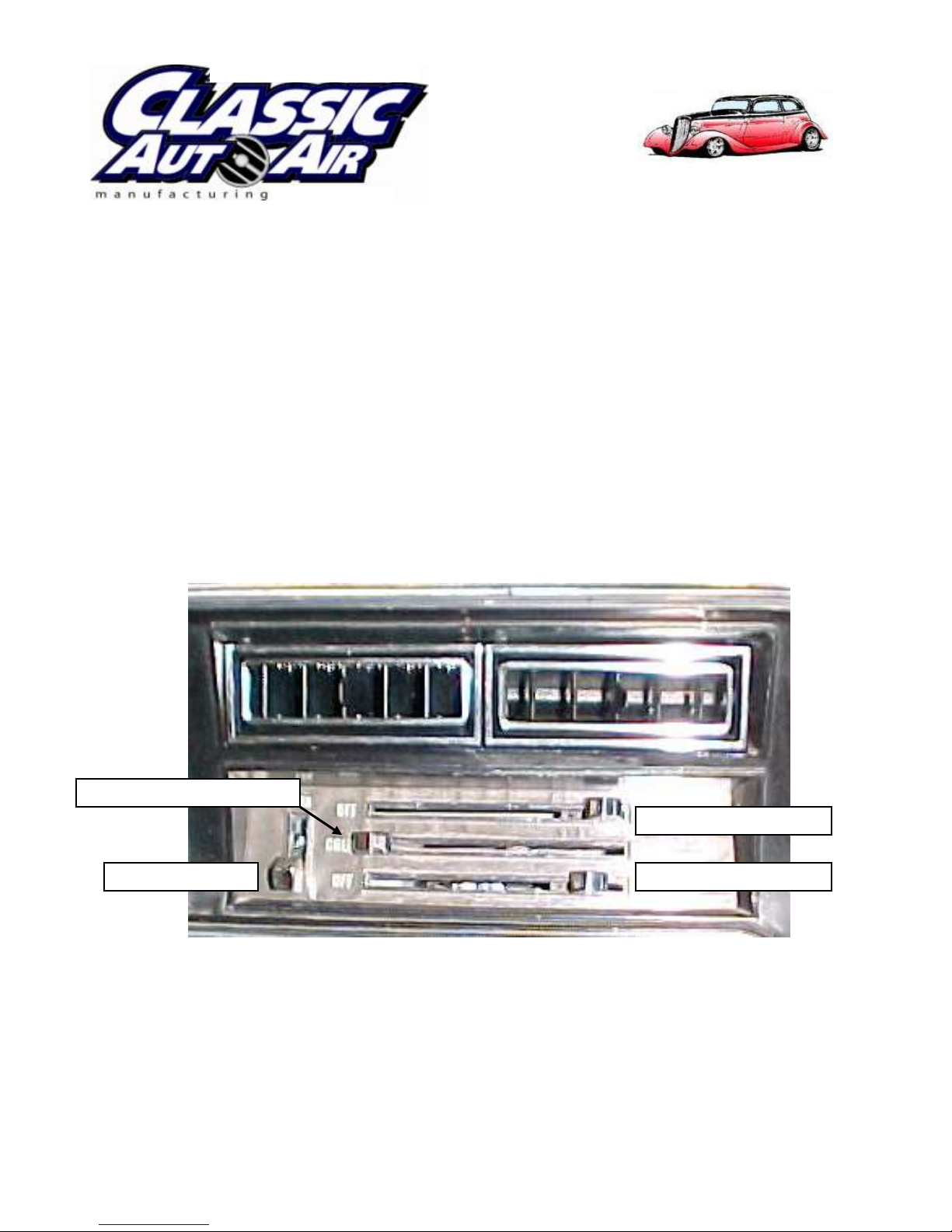
FACE / DEFROST DOOR
HEAT / DEFROST DOOR
BLOWER SWITCH
TEMPERATURE LEVER
specializing in “AIR CONDITIONING, PARTS AND SYSTEMS” for your classic
IN-DASH
HEAT/ COOL/ DEFROST
1970-72 CHEVROLET CHEVELLE/ EL CAMINO
NOTE: INSTRUCTIONS DEPICT CHEVELLE
CONTROL & OPERATING INSTRUCTIONS
The controls on your new “Perfect Fit” system. Offers complete comfort capabilities in
virtually every driving condition. This includes Temperature control in all of the modes.
This system also provides the ability to blend the air between Face, Heat, and Defrost
modes simultaneously.
THE PICTURE YOU SEE ABOVE SHOWS THE CONTROLS IN THE DEFROST
MODE. THIS MEANS THAT ALL OF THE AIR WILL BE DISTRIBUTED
THROUGH THE DEFROST DUCT ASSEMBLY. THIS ALSO HAS THE
TEMPERATURE LEVER IN THE COLD POSITION. WITH THE CONTROLS IN
THIS POSITION YOU WILL GET THE AIR THROUGH THE SYSTEM AT ROOM
TEMPERATURE.
Page 2

2
CAUTION: ALL OF THE OUTSIDE VENTS MUST BE CLOSED WHEN THE
SYSTEM IS IN THE A/C MODE. THIS WILL ALLOW THE A/C SYSTEM TO
FUCTION AT ITS MAXIMUM PERFORMANCE LEVEL.
THE FOLLOWING SUMMARY WILL DESCRIBE EACH OF THE CONTROL
LEVERS FUNCTION.
FAN SPEED SWITCH: There are 3 speeds plus Off. When the switch is in the off
position it will disconnect the 12V power to the Blower Motor and the A/C Clutch. This
will shut down the entire system. When the switch is moved to any of the blower speeds
1,2 or 3 there is 12V supplied to the Micro-Switch which is mounted on the defrost air
housing.
HEAT MODE: When the heat lever is moved towards the right, it will allow the air to
go between the floor ducts and the face louvers. Only when the lever is in the far right
position will all of the air stop coming out of the face louvers and blow on the floor.
TEMPERATURE CONTROL: The temperature lever as shown is in the
COLDEST temperature position. As the lever is pushed to the right the temperature of
the discharged air will rise to the HOTTEST point.
Note: The temperature lever will function in any of the modes.
DEFROST MODE: This system allows for Dehumidification of the air in the
Defrost mode. The Heat lever must be in the right position. The bottom lever must be at
the far right position in order to get the maximum air flow to the windshield and to trip
the Micro-Switch. This will activate the Compressor Clutch.
AIR CONDITIONING MODE: The picture shows the controls in the
Defrost Mode (air-flow to the windshield).
When Air Conditioning is required the compressor clutch must be activated. This is
accomplished by pushing the top lever to the far left position. The bottom lever must be
in the far right position to activate the clutch. When the compressor is activated the
Temperature Lever will control the air from maximum cold through maximum heat.
Page 3

3
specializing in “AIR CONDITIONING, PARTS AND SYSTEMS” for your classic
INSTALLATION INSTRUCTIONS
1970-72 CHEVROLET CHEVELLE/ EL CAMINO
NOTE: INSTRUCTIONS DEPICT CHEVELLE
Congratulations!! You have just purchased the highest quality, best performing A/C
system ever designed for you Classic Car. To obtain the high level of performance and
dependability our systems are known for, pay close attention to the following
instructions.
Before beginning the installation check the box for the correct components.
Evaporator
Face Duct Assembly
Defrost / Heat Duct Assembly
Inlet Air Blockoff Assembly
Firewall Blockoff Assembly
Flex hose 2” dia. x 2ft. – 2ea.
Flex hose 2” dia. x 3ft. – 1ea.
Flex Hose 2 ½”dia. x 2ft. – 2ea.
Flex Hose 2 ½”dia. x 3ft. – 1ea.
Sack Kit Hardware
Sack Kit Control
Center Air Plenum
IMPORTANT INFORMATION
1. Before starting, read the instructions carefully and follow proper sequence.
2. Check condition of engine mounts. Excessive engine movement can damage hoses to A/C, heater,
radiator, transcooler, and power steering systems.
3. Before starting, check vehicle interior electrical functions. i.e. interior lights, radio, horn, etc. When
ready to start installation, disconnect battery.
4. Fittings. Use one or two drops of lubricant on O’rings, threads and rear of bump for O’ring where
female nut rides. Do not use thread tape or sealants.
5. Always use two wrenches to tighten fittings. Try holding in one hand while squeezing together while
other hand holds fitting in position.
6. Shaft seals in a small percentage of compressors will require as much as 3-4 hours run time to
become leak free.
7. Compressors supplied in our complete systems are filled with proper amount of oil.
Page 4
4
8. Compressor requires technician to hand turn 15-20 revolutions before and after charging with
liquid from a charging station before running system. Compressors with damaged reed valves
cannot be warranted.
9. Should you have any technical questions, or are suspect of missing, or defective parts, call us
immediately. Our knowledgeable staff will be glad to assist you.
YOU CAN NOW BEGIN THE INSTALLATION
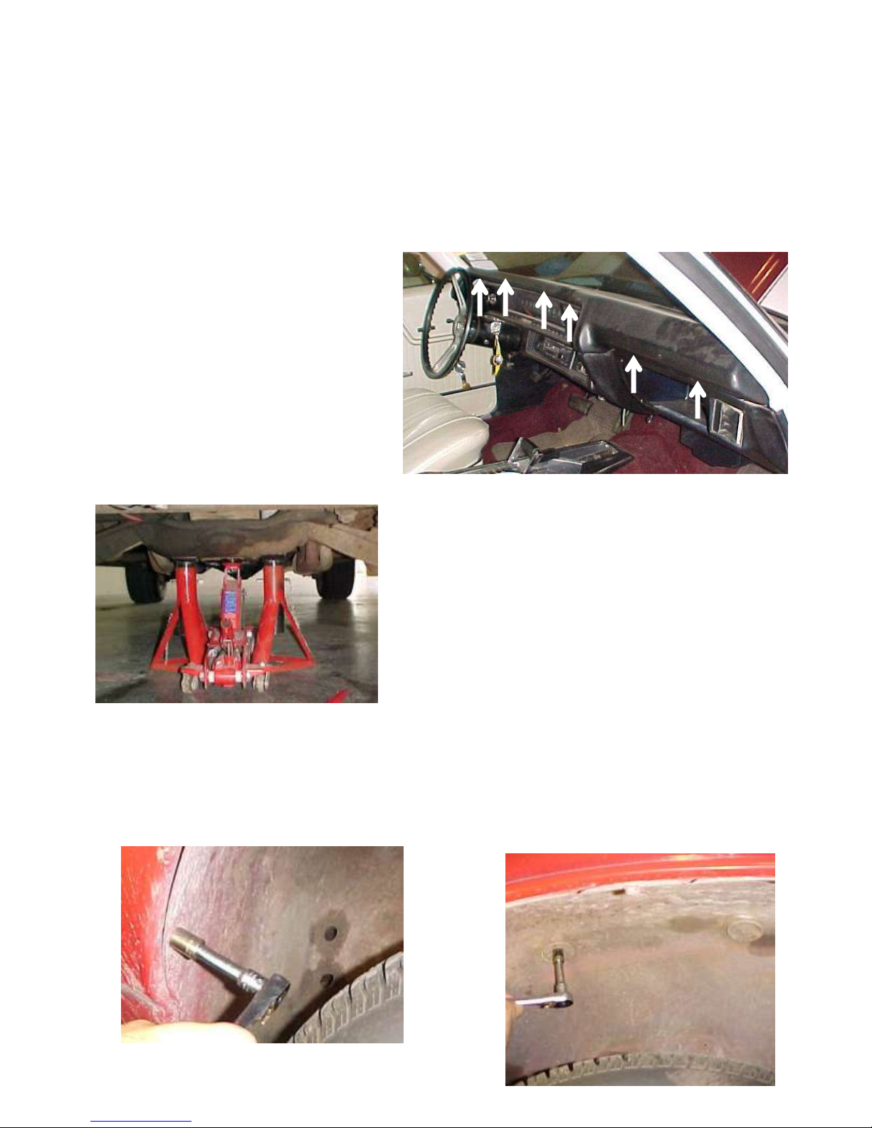
Remove (6) screws at locations
shown to remove the dash pad.
In order to remove the heater assembly. It is
necessary to remove Blower Housing Assembly
from the engine side of the firewall.
Carefully lift vehicle and place support stands under
center of the vehicle as shown.
Remove the (8) bolts. Lower the inner fender well on the passenger side.
Page 5
5
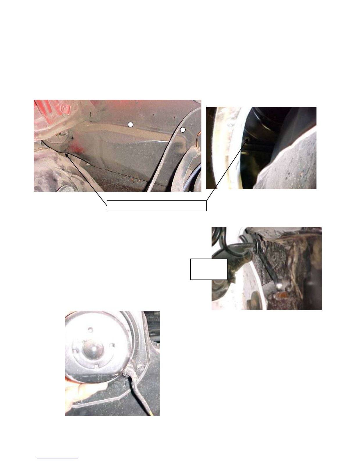
Screw location behind fender well
Hood hinge
assembly
Remove (7) screws around the perimeter of the Blower Housing. The lower left screw is
located behind the fender well.
On engine side of Firewall behind Hood hinge
assembly is one of the (7) screws holding the blower
housing. Remove and retain all of the original
hardware.
Unplug electricals from the blower motor and remove
blower assembly from the vehicle.
Page 6
6
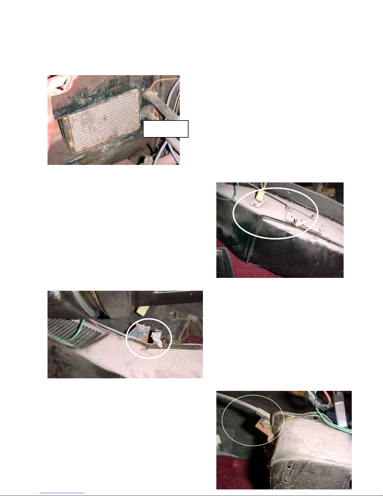
Heater Hoses
Reinstall Inner Fender Well using the original hardware.
DRAIN COOLANT FROM RADIATOR.
Remove Heater hoses from heater coil at
firewall.
Lower heater box on inside of car to the floor
board. To remove heater box from the vehicle (3)
control cables and the electrical must be
disconnected from the housing. Disconnect (1)
control cable and electrical plug located on top of
the heater box.
Disconnect (1) control cable located
next to the defrost outlet.
Disconnect final control cable located all the way
to the left of the heater assembly.
Page 7
7
You can now remove heater assembly from inside of the vehicle.
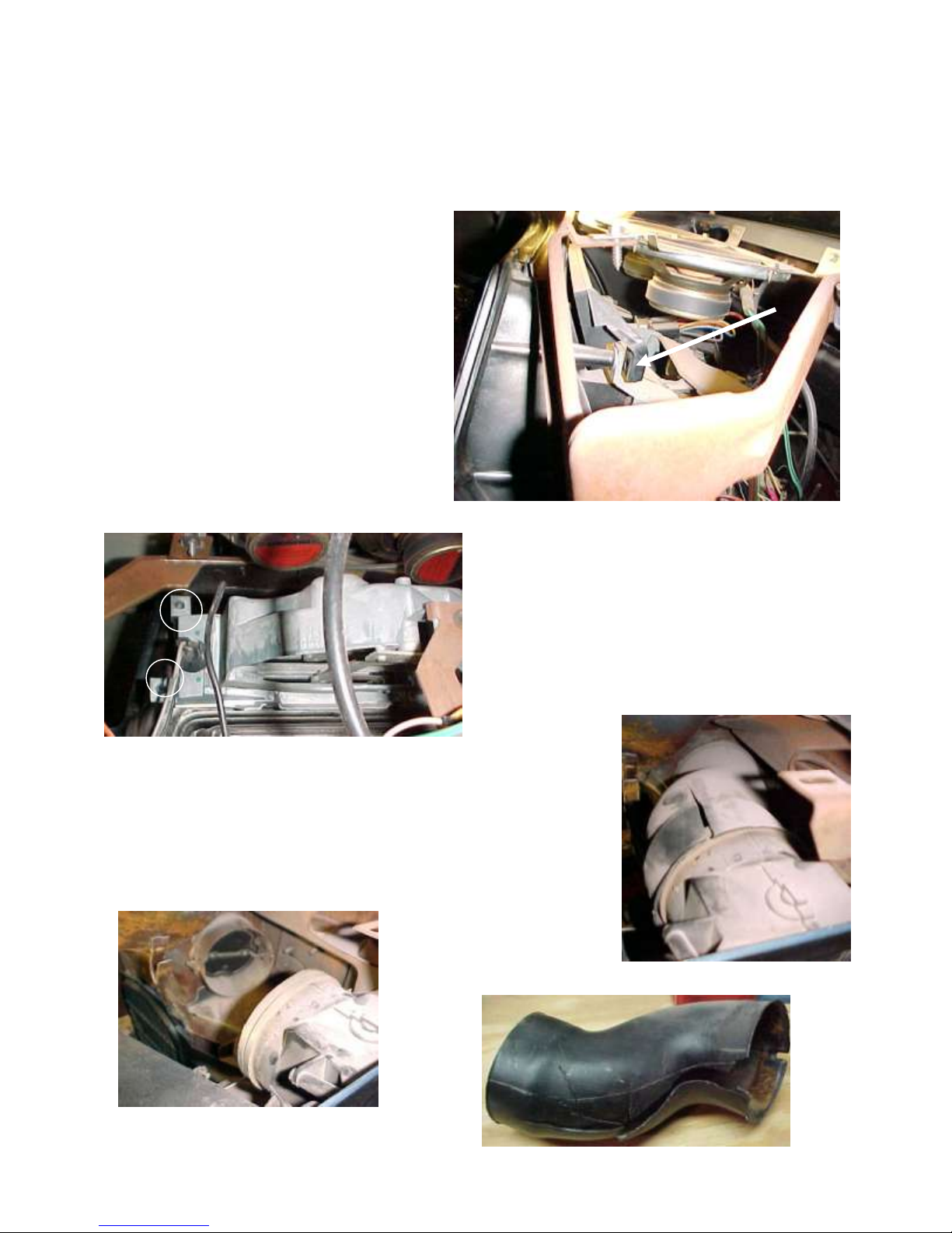
The blockoff plate above the control
head can be removed by (2) screws.
One as shown and the other on driver’s
side of the blockoff. Retain original
hardware. Remove the center speaker
assembly and retain all original
hardware.
The control head can be removed by pulling (4)
screws behind the dash. There are (2) screws on
each side of the control head. The (2) shown are on
the passenger side of the control head. Retain
original hardware.
The fresh air duct on the passenger side of the vehicle can be
removed by cutting duct with a knife and removing it from the
vehicle. The driver’s side fresh air duct can also be removed
by cutting it.
Page 8
8
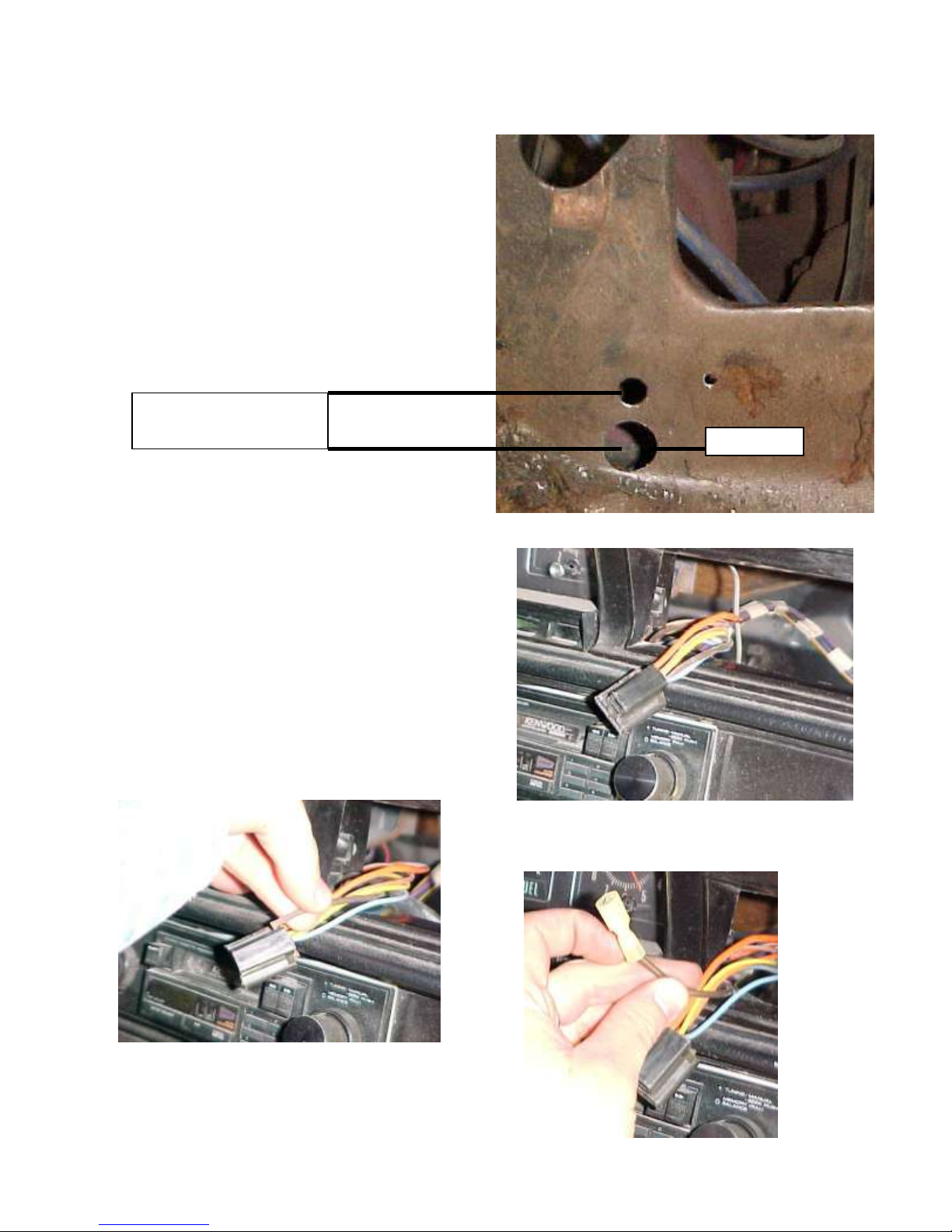
DRILL ¾” DIA. HOLE
¾” BETWEEN CENTRES
¾ “DIA.
Locate behind glove box and on firewall the
hole that previously mounted the heater box.
Drill (1) ¾” dia. hole for the drain tube as
shown.
Locate wire harness that powered the original
heater assembly and pull through the control
head hole in the dash. Locate the brown wire
and cut it at the plug. Attach (1) male insulated
spade connector to the brown wire.
Page 9
9
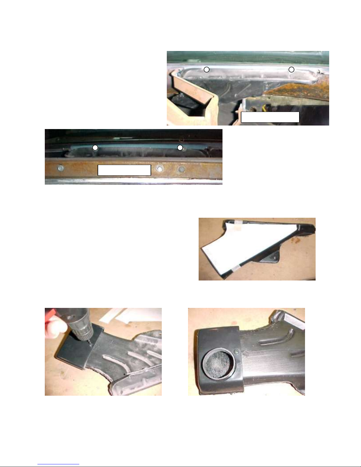
PASSENGER SIDE
DRIVERS SIDE
Remove the original defrost duct.
This is done by removing (4) screws
at top edge of the dash.
It will be necessary to cut the defrost
duct in half to remove it.
Attach passenger side defrost template to
passenger side of the defrost duct. Cut the duct
as shown. Attach ¼ x ½ open cell foam around
the duct inlet. Slide passenger side defrost duct
adapter over the foamed inlet to the edge of the
foam. Pre-Drill duct with a 5/32 drill bit on both
sides of the duct. Attach the adapter to the duct
using (2) #10 x 5/8 PHP screws.
Page 10
10
The driver’s side defrost duct can be modified using the driver’s side template and
adapter.
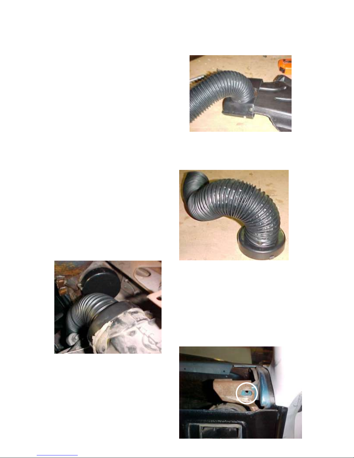
Cut off 17” of 2” flex hose and attach to the
passenger side defrost adapter with (2) #10 x
5/8 PHP screws
Cut off 20” of 2” flex hose and attach to
Drivers side defrost adapter with (2) #10 x
5/8 PHP screws
All of the modifications to the vehicle are complete we will now begin the
installation of the Unit.
Attach 30” of 2 ½” flex hose to the
passenger side louver adapter using (2) #10
x 5/8 php. Press louver adapter over the
back of the original passenger side louver.
Make sure that the flange on the dash
inserts into the s-clips. Press air inlet
blockoff over the air inlet making sure that
the s-clips are inserted correctly.
Remove (2) dash mounting bolts at
locations shown.
Driver’s side louver and air inlet blockoff can be
installed the same way. Attach 32” of 2” duct
hose to the driver’s side louver adapter.
Page 11
11
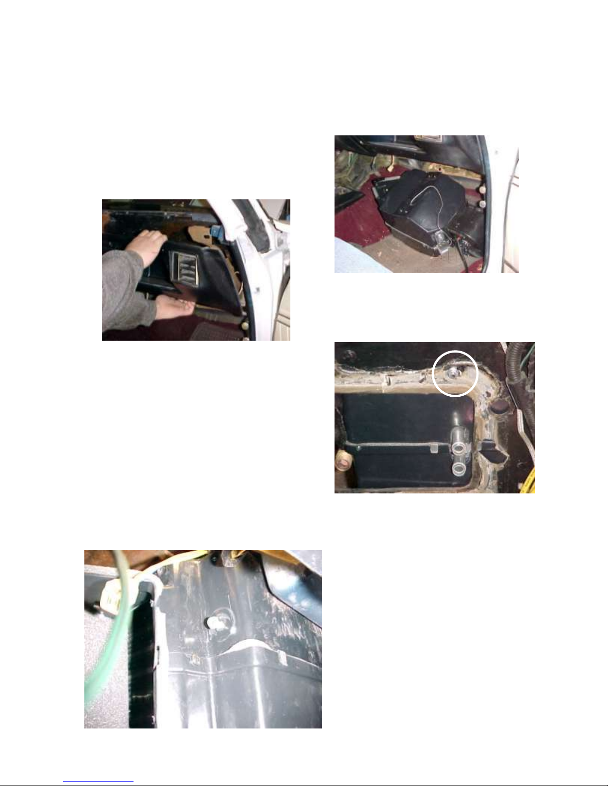
Set evaporator on floorboard of the vehicle.
Have one person carefully flex the dash towards
rear of the car while another person slides unit
behind the glove box.
Insert stud on top mounting bracket through hole
that original heater mounted to. Attach (1) ¼-20
flange nut to the stud. The drain tube should
insert through the previously drilled ¾” hole.
Reattach dash to the mounting points.
Remove #10 x ¾ hex head screw that
is located behind bottom edge of dash
on the evaporator.
Page 12
12
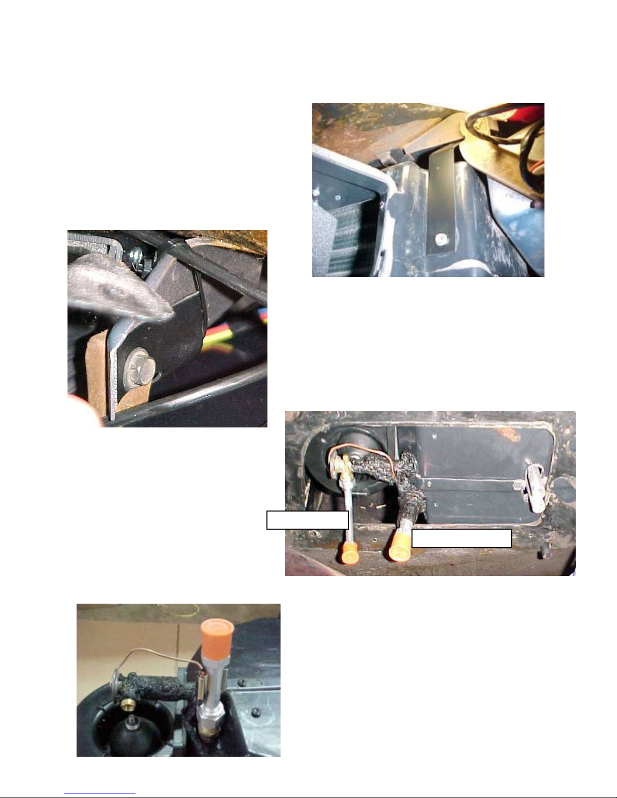
LIQUID TUBE
SUCTION TUBE
Attach the front support bracket with the
previously removed hex head screw.
Remove screw from dash support bracket. Attach
front support bracket with screw to the dash
support.
Attach suction tube to the evaporator
using (1) #10 o-ring and a few drops
of mineral oil. Attach the liquid tube
to the TXV using (1) #6 o-ring
and a few drops of mineral oil.
Locate Sensing Coil attached to the TXV and utilizing
Bulb Clamp, attach it to the Suction Tube.
CAUTION: SYSTEM WILL NOT FUNCTION
PROPERLY IF SENSING COIL IS NOT CLAMPED
IN THE CORRECT POSITION. SEE PICTURE.
Page 13
13
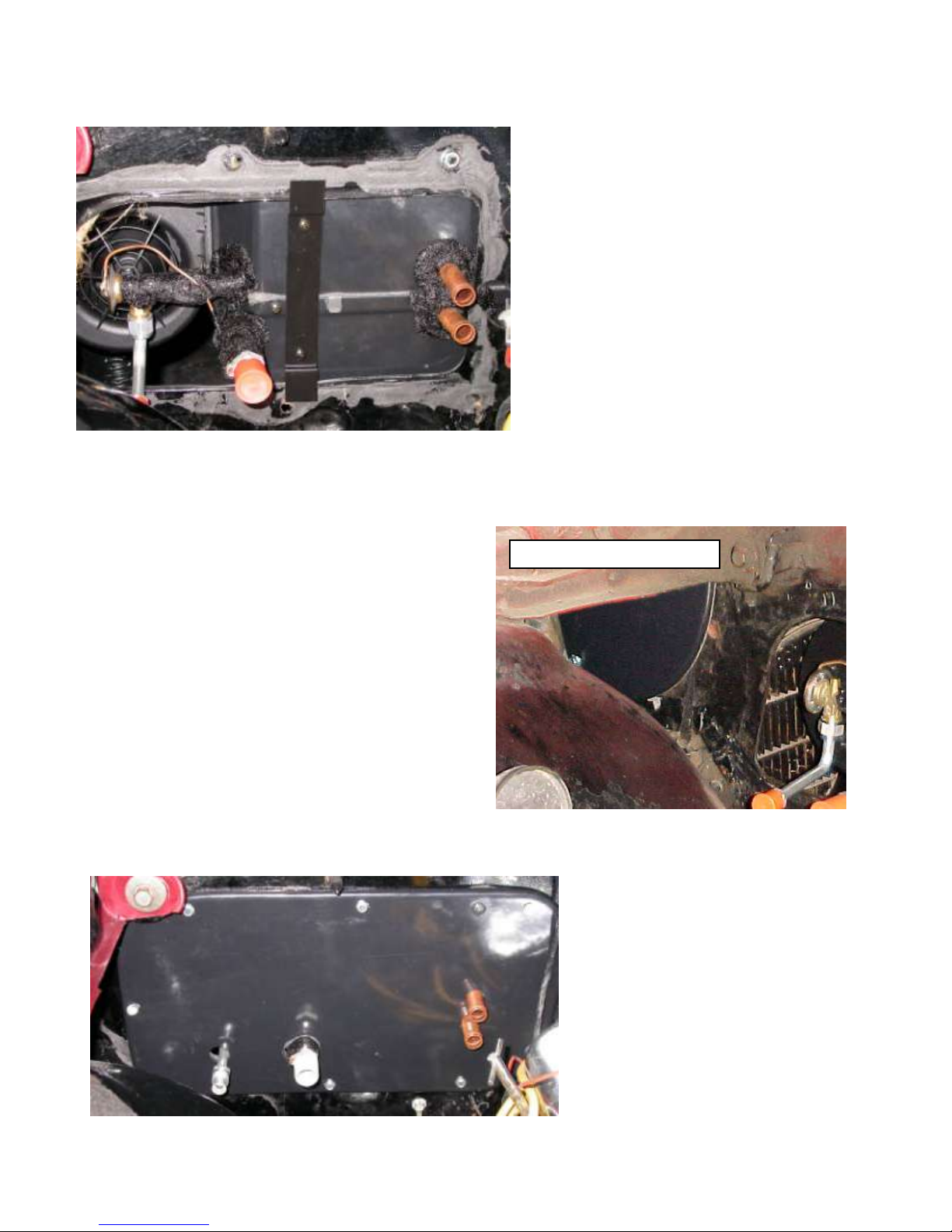
HOOD HINGE ASSEMBLY
Locate the Inlet Blockoff Plate.
Attach the blockoff behind the Hood Hinge
assembly. Use the original hardware.
Wrap Suction Tube and Sensing Coil with
refrigerant tape provided. Be sure that all of
the exposed metal is covered.
Locate in hardware sack kit is rear unit
support bracket, and (2) #10 x 5/8” pan head
Philips screws.
Using a non powered screw driver. Install
screws through bracket and into Evaporator
housing. Do not over tighten.
NOTE LOCATION OF BRACKET.
Locate the Firewall Blockoff plate, and
(6) #10 x ¾” hex head tek screws.
On engine side of firewall attach over
hookup tubes from the evaporator
using (6) #10 x ¾” hex washer head
Tek screws.
Locate refrigeration tape provided and
seal around the hookup tubes.
Page 14
14
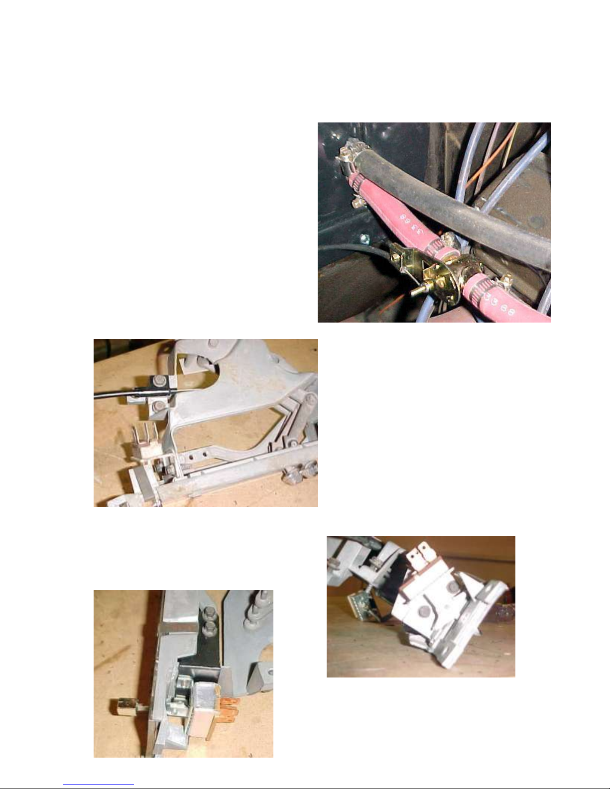
Locate the Water Valve and (3) worm gear
clamps.
Supply line from engine is attached to the
upper heater hookup tube. Cut 6” off the end
of the return line and install the water valve
using (3) worn gear clamps as shown above.
Note: It is recommended that you
replace heater hoses from the engine
to the hookup tubes.
Remove the original blower switch. Using
original switch mounting hardware install the
switch assembly as shown. Press chrome knob
onto switch lever.
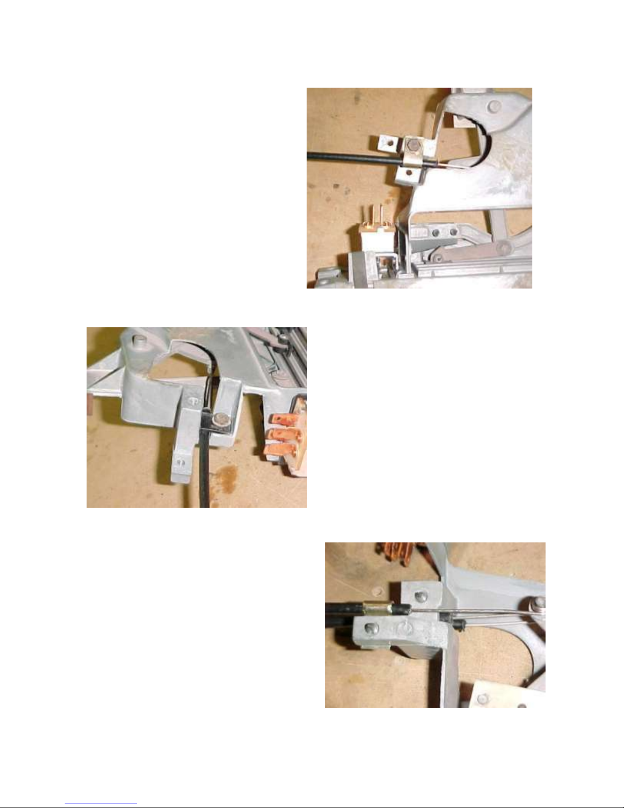
Remove three original cables from the control
head and retain all original hardware.
Page 15
15
Attach face/defrost cable to the control
head using a cable clip. This will
be the middle sized cable in the kit. This
cable will be placed on the control lever
labeled OFF to AIR on face of the control
head.
The shortest cable supplied in kit will be
installed onto the final mounting point using
a cable clip and the original hardware.
Install longest of the (3) cables supplied in
kit onto the middle mounting point of
control head using original hardware and
cable attachment bracket in the control sack
kit.
Page 16
16
Center Air Plenum
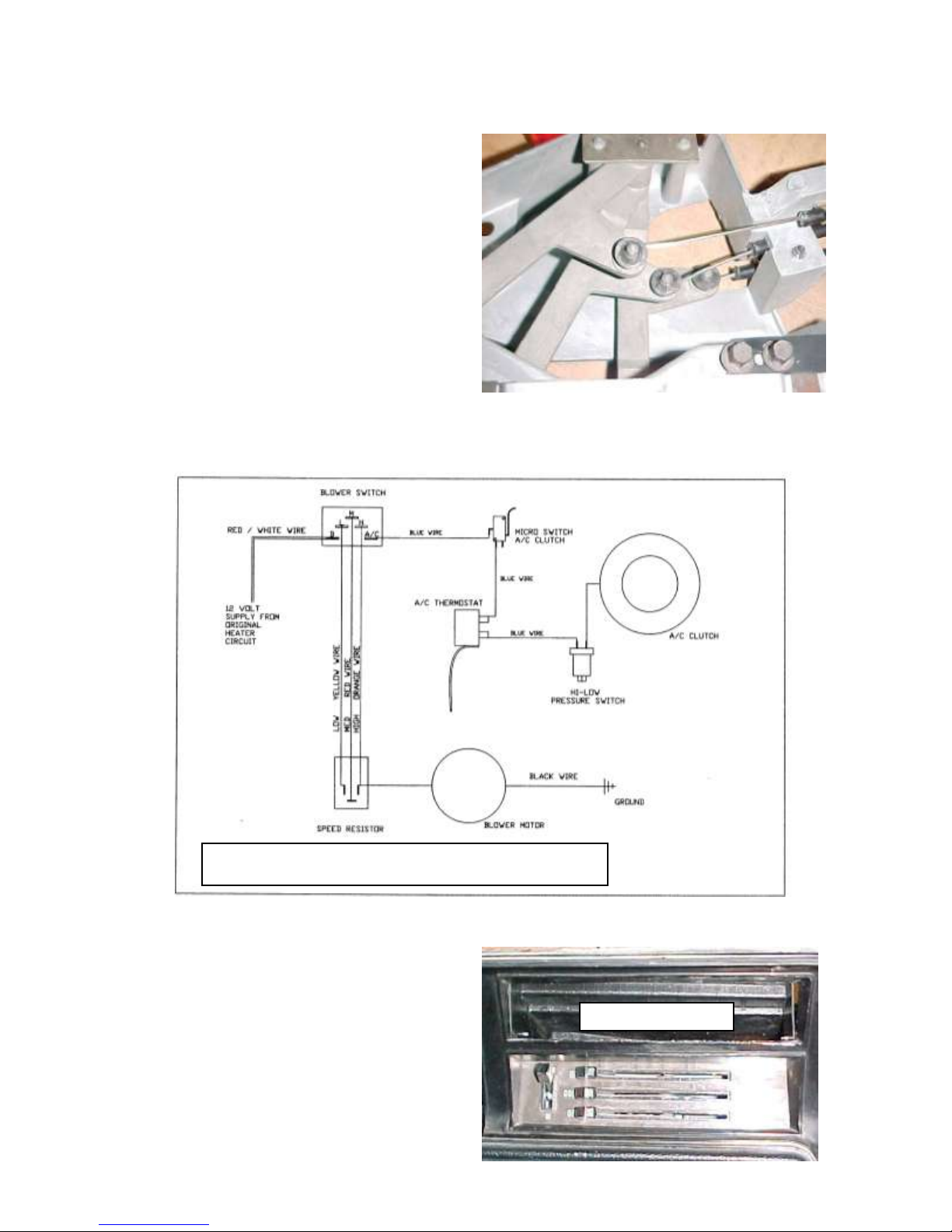
WIRING DIAGRAM 1970 CHEVY CHEVELLE
Slide the loop on the cables over the levers.
Press (3) push nuts onto the levers to hold
the cables in place.
Attach wire harness to switch on control head per the wiring diagram.
Reinstall control head using the original
hardware. Set the center air plenum into
place above the control head.
Page 17
17
Center air plenum
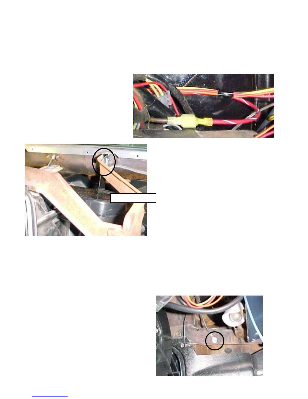
Connect power wire (brown /
from the original harness) to the
Red / White stripe from the new
harness supplied.
Attach support bracket on center air plenum
to the dash support.
Reinstall the front speakers.
Attach wire harness to the resistor block, blower motor, and thermostat per the wiring diagram
on the previous page.
Ground blower motor using the ring
terminal attached to black wire on the wire
harness. Use (1) #10 x ¾ hex head self
tapping screw behind dash on the passenger
side wall.
Page 18
18
PASSENGER SIDE
DRIVERS SIDE
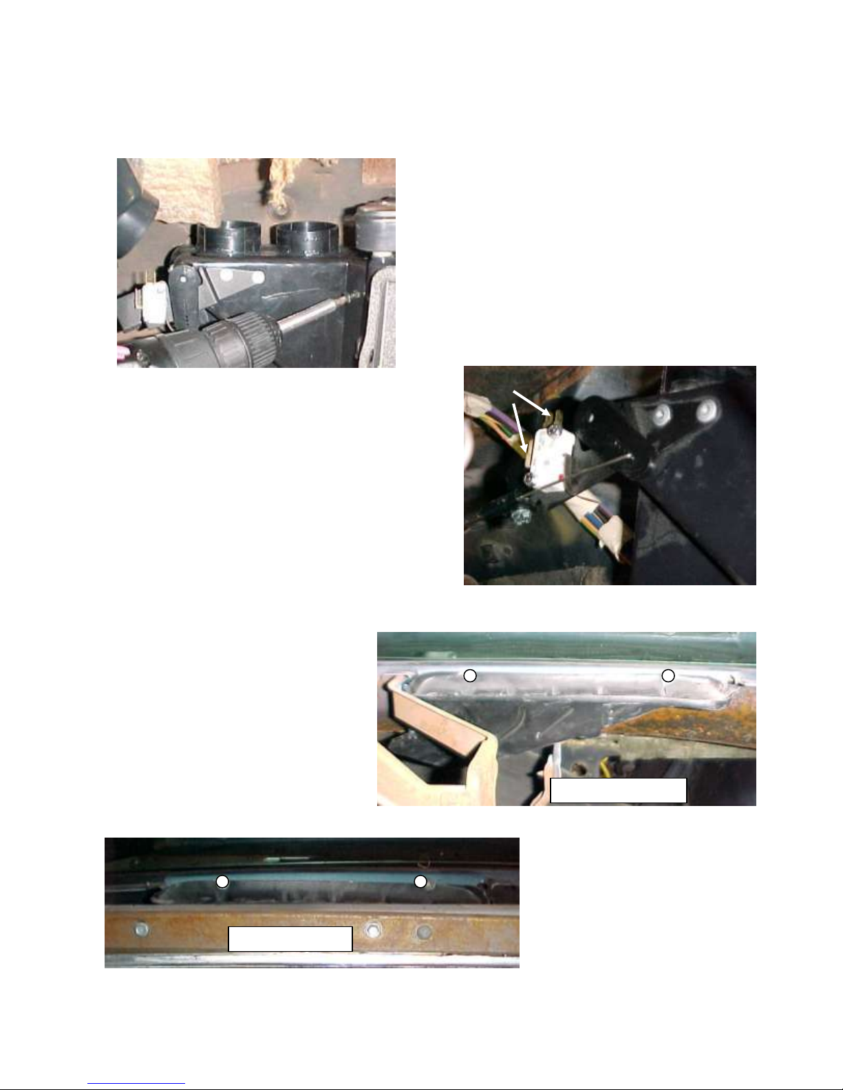
Locate the Defrost / Heat Duct Assembly.
Attach to evaporator using (2) #10 x 5/8 pan
head Philips screws. Be sure that S-clips are
pressed over the rear flange. This helps secure
the duct assembly.
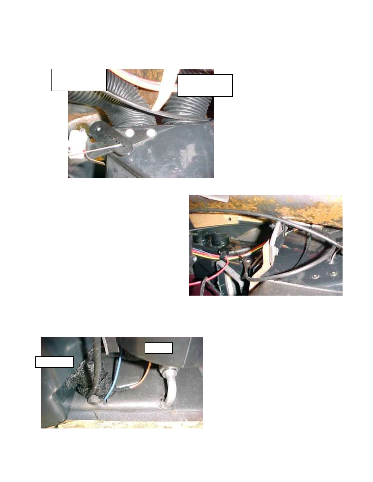
Insert defrost heat cable (bottom lever on control
head) into second hole from end of the defrost
heat duct crank arm. Attach cable to bracket
using (1) #8 x ½ PHP screw. Plug (2) blue wire
leads from wire harness into micro switch as
indicated by the white arrows. Check the lever
on control head to insure that when door is in
defrost position the micro switch is engaged.
Install defrost ducts using the
original hardware.
Page 19
19
blower
Power pack
To Driver’s Side
Defrost Duct
To Passenger’s
Side Defrost Duct
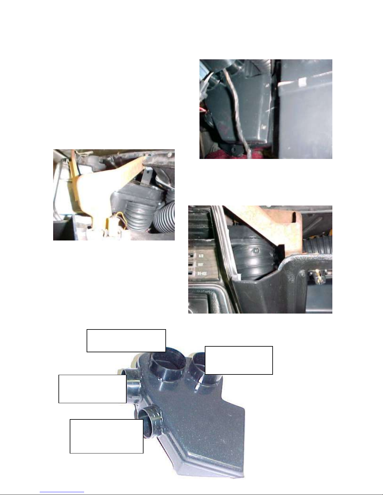
Route the face defrost cable (top cable on
the control head) around dash support and
insert cable into 3rd hole from end of crank
arm on the defrost face door. Attach cable
to the cable attachment bracket using (1) #8
x ½ PHP screw.
Route the defrost flex hose.
Route the final control cable (the longest
cable) over top of unit and through firewall
under the blower. Also insert long blue
clutch wire through firewall at the same
location.
Use a small piece of refrigeration tape to
seal the firewall.
Page 20
20
From the passenger’s
side louver (see
routing below.)
From the driver’s side
louver. Route the hose
up and behind the
instrument panel.
From the front hose
adapter on the center
air plenum
From the rear hose adapter
on the center air plenum.
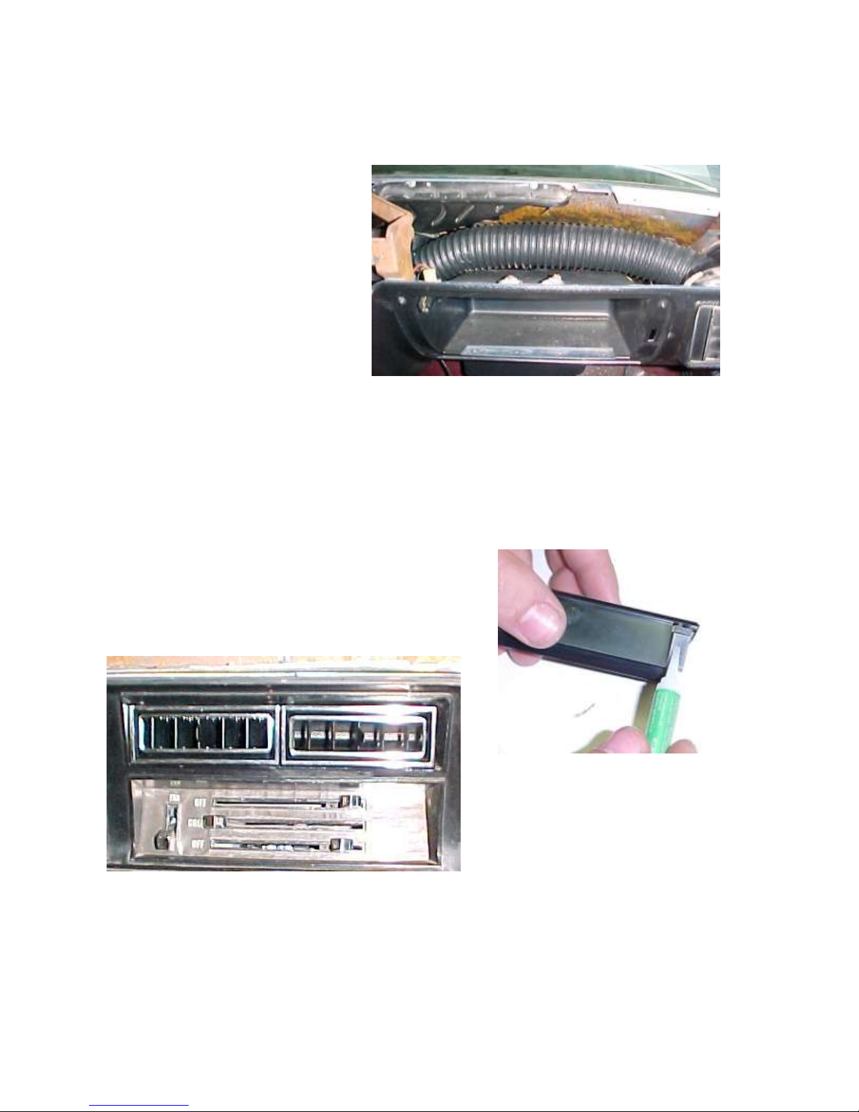
Locate the center air distribution duct.
Attach to evaporator using (2) #10 x 5/8 pan
head Philips screws. Be sure that S-clips are
pressed over the rear flange. This helps
secure the duct assembly.
Attach 16” of 2 ½” flex hose to rear hose adapter on the
center air plenum.
Attach 22” of 2 ½” flex hose to front hose
adapter of the center air plenum. Attach
duct hose to the hose adapter using (2)
#10 x 5/8 PHP screws.
Route the flex hoses as shown.
Page 21
21
Route the passenger side louver
flex hose over the glove box.
Caution: Carefully check under Instrument Panel for all cables, electrical harness,
or Flex Hose that might interfere with the safe operation of the vehicle.
Install dash pad using the original hardware.
Apply a small bead of adhesive to all (4) clips on the
(2) chrome louvers in the hardware sack kit. Insert
louvers into dash opening above the control head.
Installation of the interior components is complete. We will now install under hood
portion of the system.
Drain and remove the radiator and fan shroud.
Page 22
22
TOP
3RD HOLE FROM BOTTOM
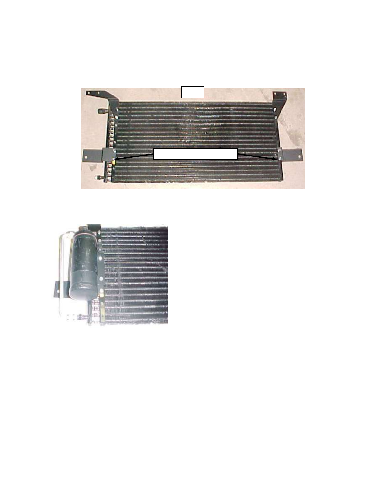
Locate the condenser, (4) condenser mounting brackets, and (8) #10 x 3/8 hex head screws.
Attach brackets to the condenser as shown.
Using (2) #10 x 3/8 hex head screws attach the drier and
drier bracket to the condenser so that the condenser-drier
tube fits properly.
Slide condenser in front of the bulkhead and behind the hood latch assembly. Attach
condenser to the existing holes in the bulkhead using (6) 5/16 x ½ hex head bolts.
Locate the discharge tube and (1) #8 o-ring. Apply a few drops of lubricating oil to o-ring fitting
on discharge tube and attach tube to top fitting on the condenser utilizing a 1” wrench on the tube
fitting and a 7/8” backup wrench on the condenser fitting. The tube should travel along the top
edge of the condenser.
Page 23
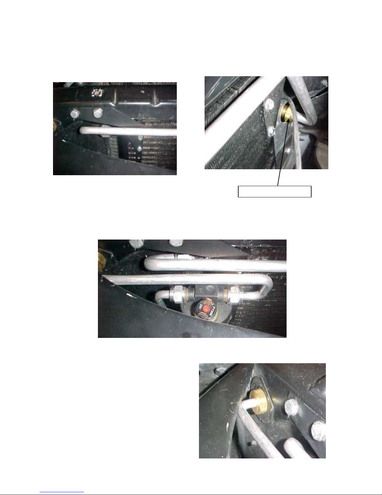
23
Locate (2) discharge bulkhead flat washers. Slide one flat washer over bulkhead fitting and
BULKHEAD FITTING
insert the bulkhead fitting through existing hole on driver’s side of the bulkhead. Attach
bulkhead nut on engine side of the bulkhead.
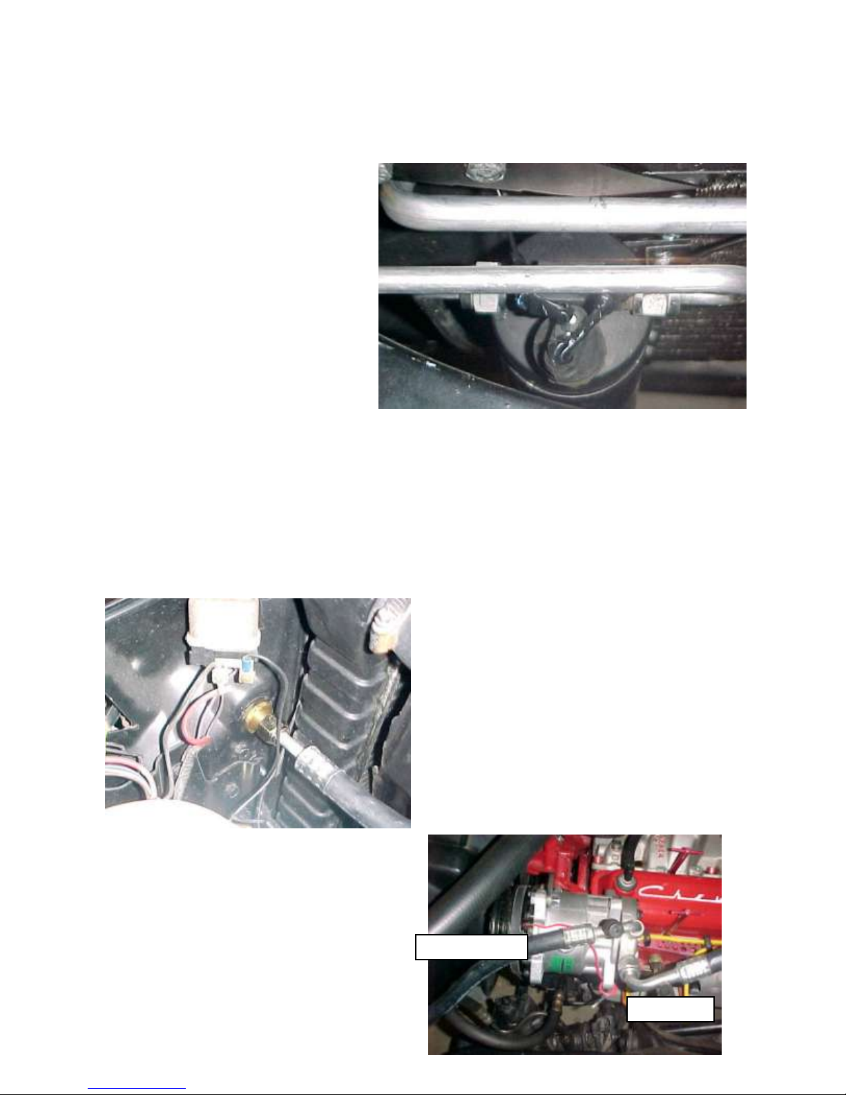
Locate the liquid bulkhead tube, (1) #6 o-ring, and hi/low pressure switch. Attach liquid
tube to the drier using (1) #6 o-ring and few drops of lubricating oil and a ¾” open end
wrench.
Attach bulkhead fitting on the liquid tube to
original hole on passenger side of the
bulkhead. Use one bulkhead flat washer on
each side of the bulkhead.
Page 24
24
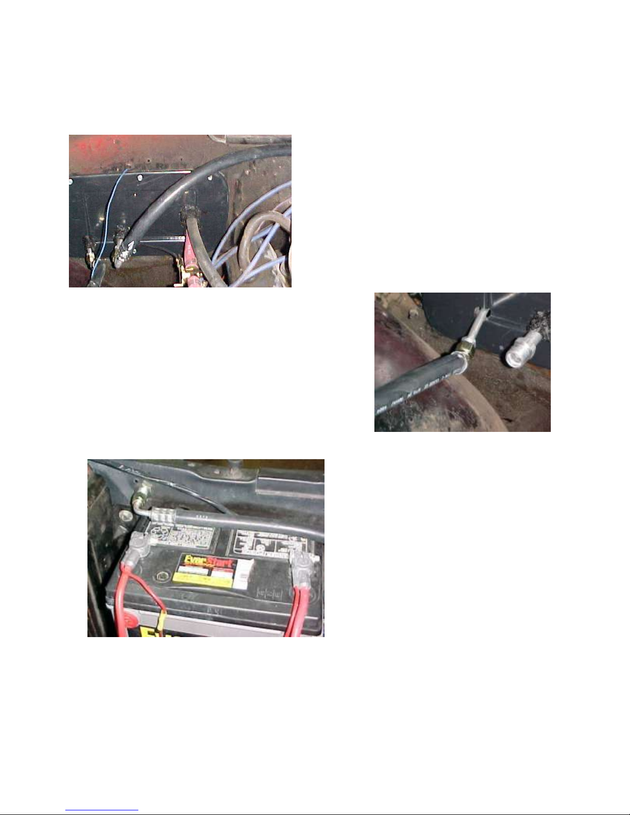
DISCHARGE
SUCTION
Plug in hi/low pressure switch wires
into top of the hi/low pressure
switch.
Route the (2) white wires through
the grommet along with #6
refrigerant hose. One of the wires
attaches to Blue Clutch wire from
thermostat and the other to the
compressor clutch.
INSTALL THE COMPRESSOR ADAPTOR KIT AND COMPRESSOR AT THIS
TIME PER THE MANUFACTURERS DIRECTIONS.
NOTE: THIS INSTALL IS CORRECT FOR A 350CID V8 ENGINE, WITH
ALTERNATOR ON PASSENGER SIDE OF VEHICLE.
IF YOUR VEHICLE IS EQUIPTED WITH A DIFFERENT ENGINE PACKAGE
IT WILL BE NECESSARY TO ROUTE THE HOSES DIFFERENT
Locate the #8 discharge hose. Attach
straight fitting to the previously installed
bulkhead fitting on driver’s side of the
vehicle.
Route hose to the compressor and attach the
90 degrees fitting with service port to
appropriate outlet on the compressor. .
Attach using (1) #10 o-ring and a few drops
of lubricating oil.
Attach 90 degree fitting with service port
on #10 suction hose to the compressor.
Attach using (1) #10 o-ring and a few
drops of lubricating oil.
Page 25
25
Attach 90 deg. end of the #10 suction
hose that does not have the service port to
#10 fitting at the firewall. Attach using
(1) #10 o-ring and a few drops of mineral
oil.
Tighten securely.
Locate the #6 liquid hose. Attach the 45 degree fitting
to the firewall using (1) #6 o-ring and a few drops of
mineral oil.
Route the liquid hose across fender well
and behind the battery. Attach 90 degree
fitting on liquid hose to bulkhead fitting
next to radiator on passenger side of the
vehicle using (1) #6 o-ring and a few
drops of lubricating oil.
Reinstall the battery, radiator and fan shroud using original hardware.
THE ENGINE COMPARTMENT OF YOUR SYSTEM IS COMPLETE.
THE UNIT IS READY FOR EVACUATION AND CHARGING.
Page 26

26
THIS SHOULD BE DONE BY A QUALIFIED AND CERTIFIED AIR
NOTE: COMPRESSOR IS SUPPLIED WITH THE
CORRECT OIL CHARGE. DO NOT ADD OIL TO SYSTEM.
134A SYSTEMS 24 oz OF REFRIGERANT
CONDITIONING TECHNICIAN.
Congratulations you have completed the install of your
CLASSIC AUTO AIR PERFECT FIT SERIES climate
control system.
Page 27
27
NOTE: COMPRESSOR PURCHASED WITH KIT IS
SUPPLIED WITH THE CORRECT OIL CHARGE. DO NOT
ADD OIL TO SYSTEM.
134A SYSTEMS 24 oz OF REFRIGERANT
Recommend that power fuse is 25amp minimum
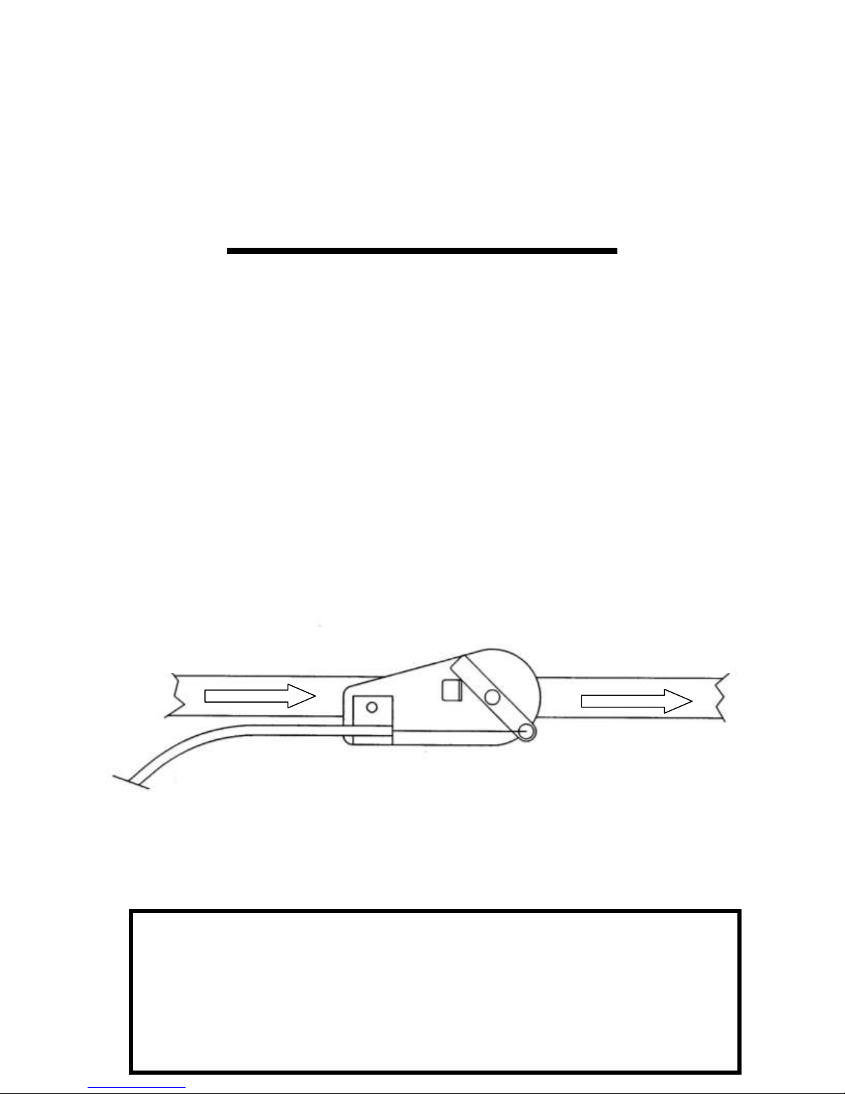
TO WATER PUMP
FROM HEATER CORE
COOLANT FLOW
IMPORTANT
CAUTION: WATER VALVE MUST BE INSTALLED PER
THE INSTRUCTIONS.
Classic Auto Air has done extensive testing on the correct method to install the water valve in order to get a
repeatable and progressive temperature control.
Locate the bottom connection from the evaporator/heater unit off of the firewall and attach a 6” piece of
5/8” dia. heater hose with the supplied hose clamp. Next attach the inlet side of the water valve using
another supplied hose clamp, (make sure the arrow on the water valve points toward the engine) Attach a
heater hose from the outlet side of the water valve and route to the connection on the water pump.
NOTE: WATER VALVE = WATER PUMP
CAUTION: WATER VALVE MUST BE INSTALLED ON HEATER LINE ROUTED TO
WATER PUMP.
 Loading...