

Classic AutoAir Perfect Fit-Elite Series Installation Manual
DOCUMENT #1-2079
©2012 ClassicAutoAir / 6.12revA
©
1964-1967 Pontiac GTO


You have just purchased the highest quality, best performing
A/C system ever designed for your Classic Vehicle.
To obtain the high level of performance and dependability our systems are known for, please pay close attention to the
following instructions. Our installation steps and procedures are derived from a long history of research and
development and the combined experience achieved thru thousands of successful installations (and feedback from
customers like you). Please remember that our #1 goal is that you’ll have a successful installation and a system that
performs at a very high level for many years to come.
Before starting, read the instructions carefully, from beginning to end, and follow the proper sequence. On the next
page you’ll find a safety and general checklist that you should read before starting your installation.
Again, thank you from our entire staff.
Congratulations...
www.classicautoair.com • 866.435.7801

4
Check List, Pre-Installation:
Procedures, During Installation:
Before beginning the installation check the shipping box for the correct components. YOUR BOXED UNIT INCLUDES A LIST OF
MAJOR COMPONENTS AND A LIST OF BAGGED PARTS. We have a 5 stage check process to make sure you have everything you’ll
need.
If your vehicle has been or is being modified, some procedures will need to be adjusted to fit your particular application.
A basic cleaning of the engine compartment and interior before beginning will make things go more smoothly.
Check condition of engine mounts. Excessive engine movement can damage hoses to A/C and/or heater.
Before starting, check vehicle interior electrical functions (interior lights, radio, horn, etc). Make a note of anything that does not work as
it’s supposed to. During the installation you might find the opportunity to repair or upgrade non-working or out of date components.
When you’re ready to start the installation, DISCONNECT THE BATTERY FIRST.
Drain the radiator. Retain the coolant and reuse, or dispose of properly.
SAFETY FIRST: Wear eye protection while drilling/cutting, deburr sharp edges, and never get in a hurry or force a part.
Tools: Your installation only requires the basic tools everyone has in their garage, nothing exotic or specific to A/C or Heat equipment.
Fittings: Use one or two drops of mineral oil (supplied with your kit) on ALL rubber o-rings, threads and rear of bump for o-ring where
female nut rides. Do not use thread tape or sealants.
Measure twice (or more), cut once
Should you have any technical questions, or feel you have defective components (or missing items), call us immediately,
we will be glad to assist you. Our toll-free number is listed on every page, we’re here to help!
YOU CAN NOW BEGIN THE INSTALLATION...
www.classicautoair.com •
866.435.7801
5
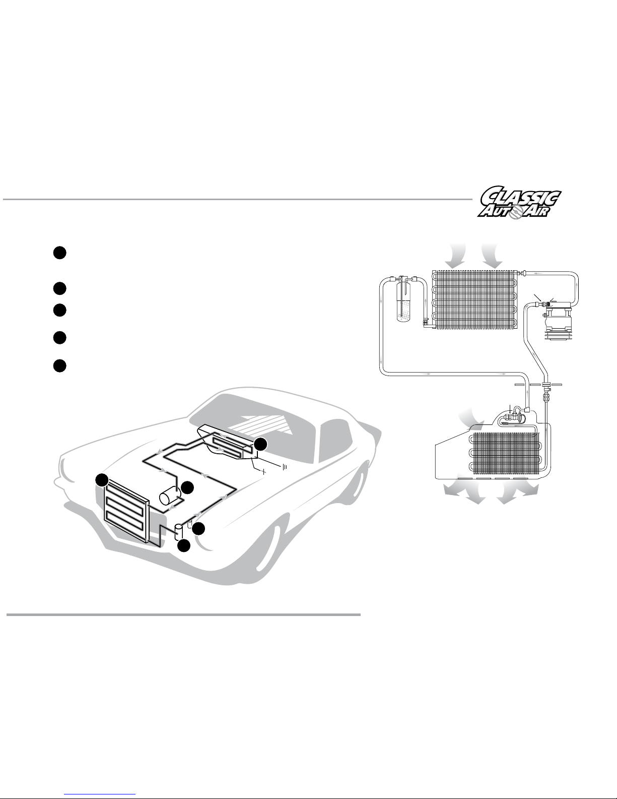
The air conditioning system in your car is comprised of a compressor, condenser,
expansion valve, receiver/drier, and evaporator. Refrigerant (also known as Freon) is
compressed in the compressor and turns into a gas. In the condenser, this gas is cooled to a
liquid state and travels to the expansion valve. As the liquid refrigerant goes through the
expansion valve it rapidly cools in the evaporator. A fan blows over the evaporator and cools the
air that blows out your vents. The receiver-drier separates gas and liquid.
Evaporator with Blower Fan
In order to remove the heat from the air in the vehicle, the A/C
evaporator allows the refrigerant to absorb the heat from the air passing over it. The blower fan moves cool air out into the car
interior.
Compressor
The compressor pumps and circulates the refrigerant through the system.
Condenser
The condenser is a heat exchanger mounted at the front of the vehicle. Heat drawn out of the interior of
the car is expelled here.
Receiver/Drier
The drier not only dries refrigerant, it also filters the refrigerant and stores it under certain
operating conditions.
High Pressure Switch
A pressure switch is used to shut down the system if high or low pressure is
detected, basically it acts as a safety switch.
A Basic A/C Overview
www.classicautoair.com • 866.435.7801 • OVERVIEW
Receiver
Drier
Compressor
Evaporator Unit
Expansion Valve
Condenser
Suction
Valve
Discharge
Valve
Firewall
OUTSIDE AIR
COLD AIR INTO V EHICLE
AIR FROM INSIDE VEHICLE
GROUND
POWER
SUCTION HOSE
DISCHARGE HOSE
LIQUID HOSE
1
1
2
3
4
5
2
3
4
5
COOLED AIR
6
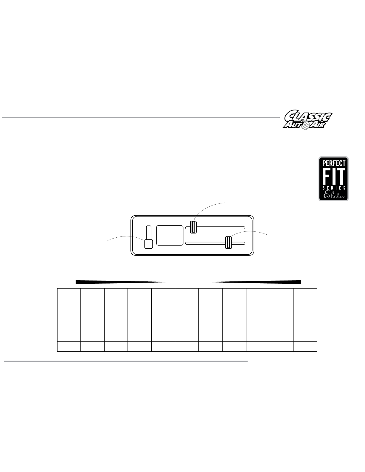
Control & Operating Instructions
Your new Perfect Fit-Elite system offers complete comfort capabilities in virtually every driving condition. This
includes temperature control in all of the modes. This system also provides the ability to blend the air between Face,
Heat, and Defrost modes simultaneously. To illustrate the various ways you can adjust the airflow direction and
temperature - we’ve provided these handy illustrations and chart to show exactly how you can adjust your
Perfect Fit-Elite for maximum comfort...
ON ON
Lever Postion
Distribution
Compressor State
1 2345678 91011
Face A/C
100%
Face A/C
80%
Defrost
20%
Face A/C
60%
Defrost
40%
Face A/C
40%
Defrost
60%
Face A/C
20%
Defrost
80%
Defrost
100%
Floor
20%
Defrost
80%
Floor
40%
Defrost
60%
Floor
60%
Defrost
40%
Floor
80%
Defrost
20%
Floor
100%
DASHFLOOR DEF
www.classicautoair.com • 866.435.7801
There are 11 levels of adjustment within
the range of the DASH/FLOOR lever
HI
MED
LO
OFF
AIR
TEMP
NORMAL – DE-ICE
WARMER
FAN
TEMP
MODE
The FAN switch works like the OEM switch,
the lowest position is OFF (all power to the
system is OFF in this position)
The COLD/HOT positions works like any
traditional adjustment lever
7
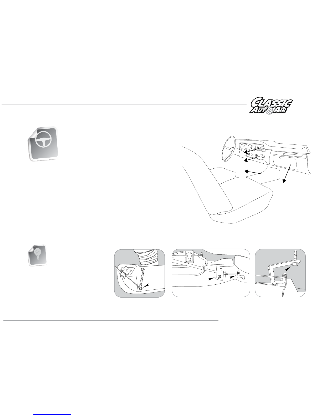
Remove Glovebox, Console (if
equipped, optional) Radio, Heater
Control Head, and Bezel, and set
them aside for reinstall later
(see figure 1).
The removal of the Original Heater Assembly can be
accomplished by disconnecting three control cables. One is
attached to the Heat/Defrost door (see figure 2). One is
attached to the Temperature door, and one is attached to the
Vent / Heat door (see figure 3). Disconnect the electrical
harness from the assembly. Also remove attachment screw
located in front of the air inlet (see figure 4).
Remove the OEM heater assembly, it will not be reinstalled.
FIGURE 4
FIGURE 3
FIGURE 2
INTERIOR
COMPARTMENT
When retaining parts it’s a
good idea to store parts in a
zip lock bag, labeled with
info where the parts came
from and what size/type of
tool is needed to reinstall. Cleaning
the parts before you need to reinstall
them is a good idea too.
GOOD IDEA
www.classicautoair.com •
866.435.7801

NOTE: Illustrations NOT shown actual size
Blower Switch
PN#3T-325
Push Nuts
PN#PD156007PG
Two Cable Clips
PN#25-1015
One U-Clip
Ground
Ground
OEM Power
Supply
ECU
Pressure Switch
(engine compartment)
Thermostat
Relay
Blower Switch
Connection
Fan
Plug
THESE ARE THE PARTS YOU WILL FIND IN BAG KIT A
You will use all of these parts and hardware during the next series of installation steps.
Cable Integrators
PN#16-2030
Wire Harness -
Power Supply
PN#0105-36
Two #6 - 20x3/8" Screws
Two Washers
Blower Switch Knob
www.classicautoair.com • 866.435.7801
PAGE
8
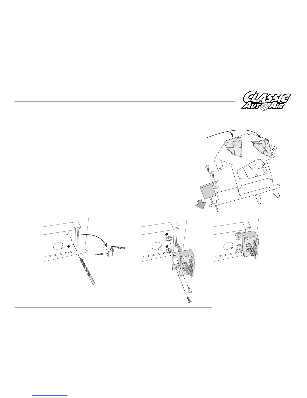
Modifying the Heater Control Head
1) Remove the OEM blower switch knob. Retain the screws, you will use them
again shortly. Remove the control cables and the original blower switch and set
aside (these will not be reused). Also, you will need to remove the two OEM
plastic cable cams (as shown to the right).
2) You will need to drill one new hole in order to attach the new blower switch.
You can use the new switch as a guide as to where to drill the new hole. Drill a
1/8” dia. hole.
3) Attach the new blower switch with bracket as shown below, utilizing the
included two #6 - 20x3/8" screws, and use the two included washers under the
bracket also.
4) Attach the new blower switch knob.
(OEM switch
not reinstalled)
This completes the new blower switch installation.
Remove
both cams
www.classicautoair.com • 866.435.7801
PAGE
9
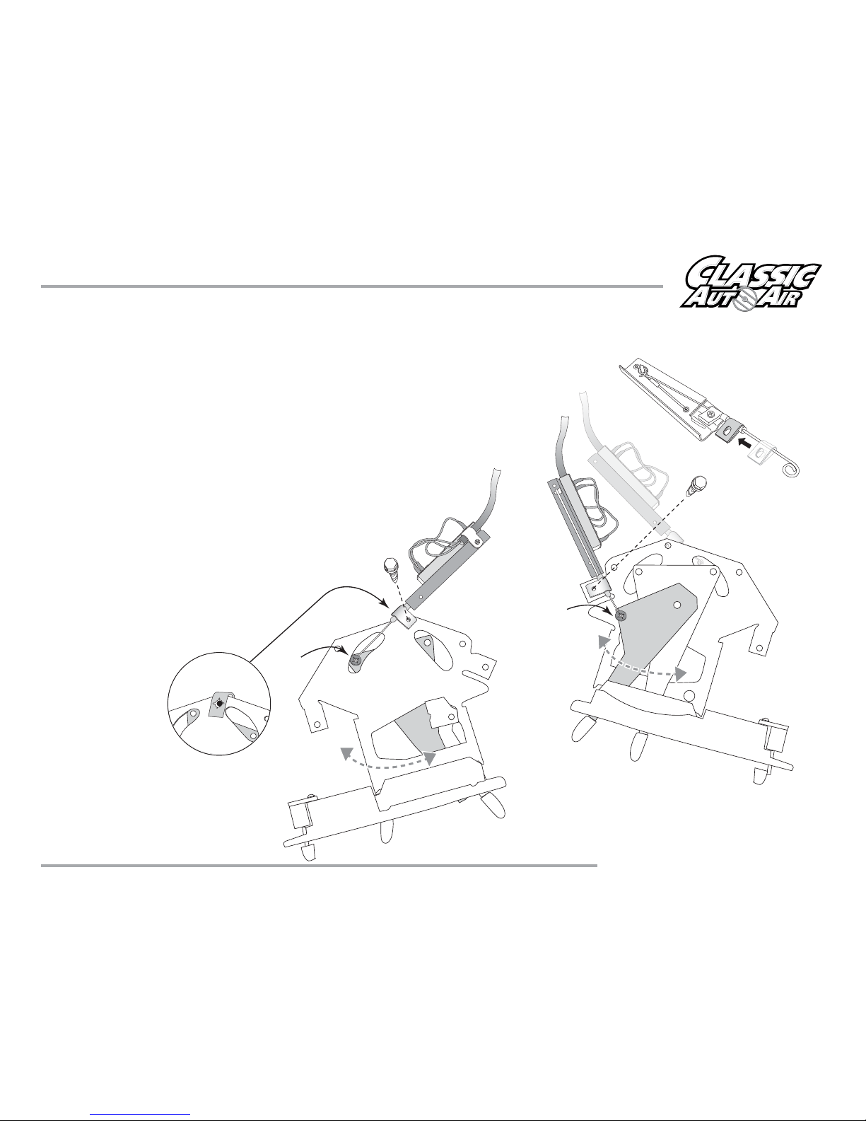
Preparing the EZ Cable Integrators for installation: First place the included cable clips
over the ends of the EZ Integrators (as shown in figure 5). Prepare both integrators the same
way.
Next, attach the TEMP EZ Cable Integrator to the control head as show in figure 6. Attach
to the body (utilizing an OEM screw that held a cable). The loop ends of the integrator
will be secured with an included push-nuts.
Flip the control head over and follow the same procedure for
mounting the MODE EZ Cable Integrator. Place the included
U-Clip over the OEM hole in the control head (see inset
below on figure 7). Mount the Intergrator utilizing the
OEM screw that held a cable. Use the remaining
push-nut to secure the cable end over the post on
the OEM control arm.
With this completed you can
attach the included harness
to the blower switch and
reinstall the control head
back in the dash.
FIGURE 6
PUSH-NUT
FIGURE 7
FIGURE 5
BOTTOM
TOP
MODE
PUSH-NUT
OEM SCREW
U-Clip
TEMP
OEM SCREW
www.classicautoair.com • 866.435.7801
PAGE
10
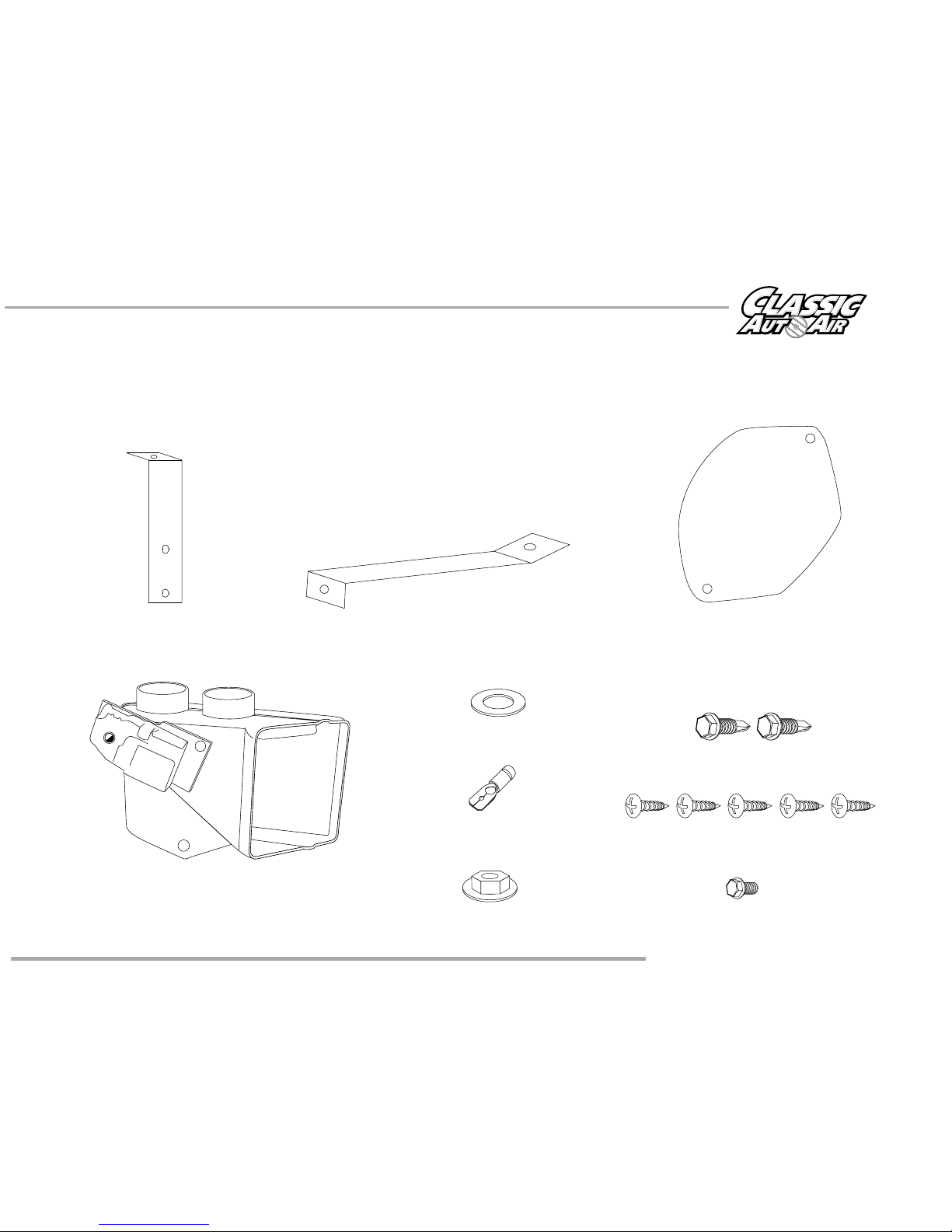
11
Illustrations NOT shown actual size
Two #10 - 16 x 3/4" Tek Screw
Five #10 - 10 x 5/8" Phillips Screws
Evaporator Support Bracket
PN#0040-10
Fresh Air Inlet Block Off
PN#10-1048-2
Defrost/Heat Duct Assembly
PN#2-2025-2
One Flange Nut
One Male Spade Connector
One 1/4 #20 x 5/8” Hex Head Screw
THESE ARE THE PARTS YOU WILL FIND IN BAG KIT B
You will use all of these parts and hardware during the next series of installation steps.
Evaporator Support Bracket
PN#0040-11
www.classicautoair.com • 866.435.7801
One Washer
12
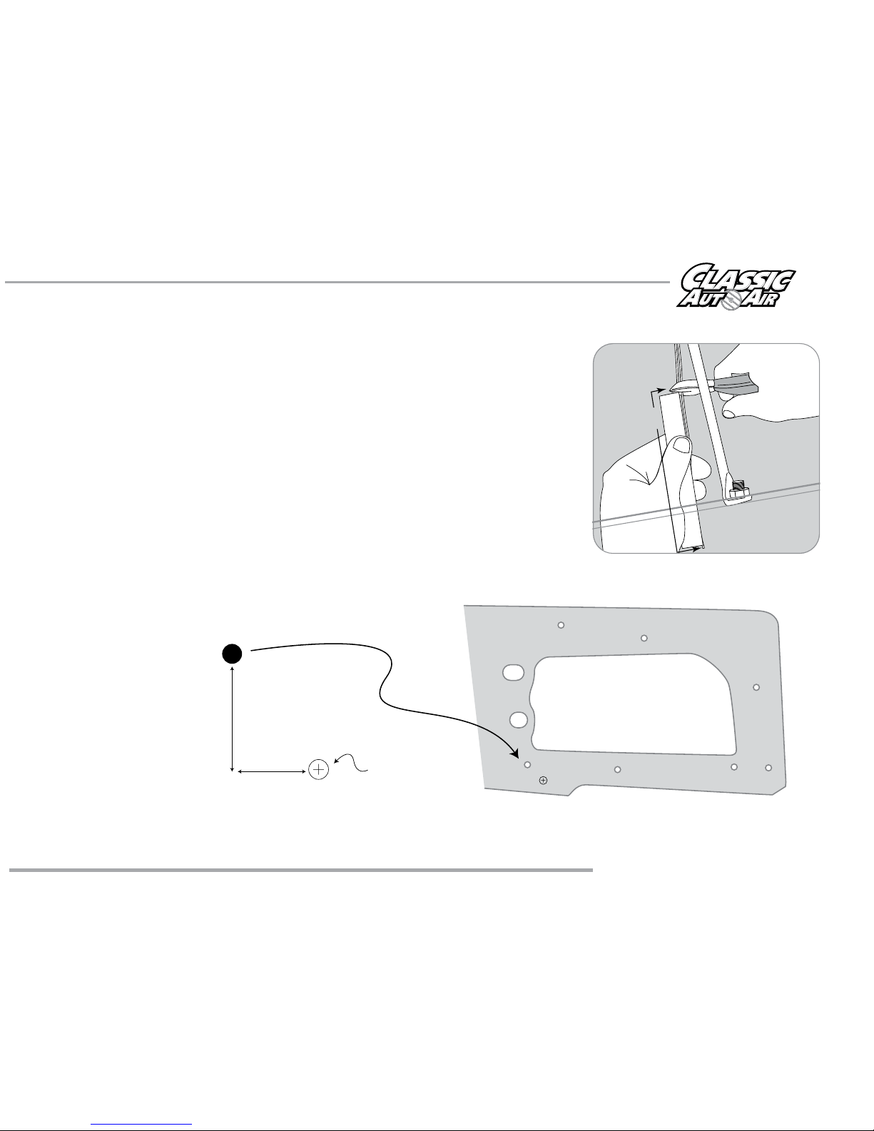
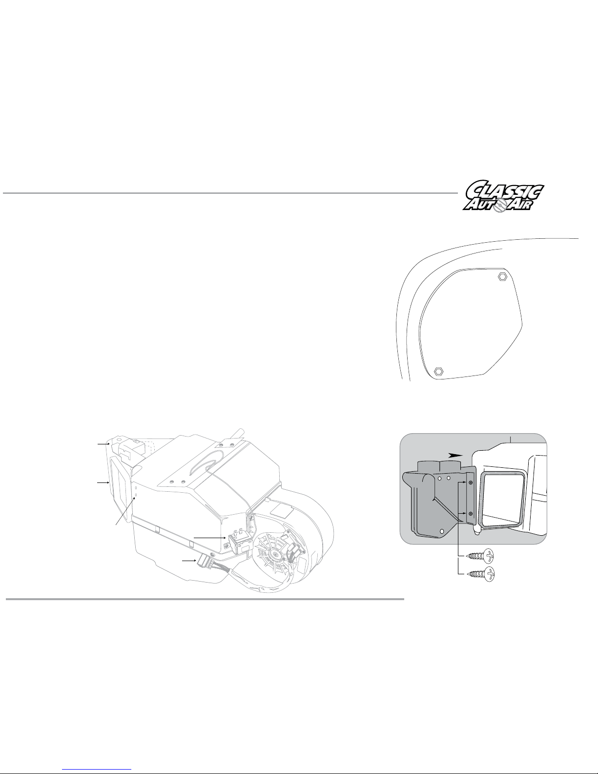
You can now begin installing your Classic Air Perfect Fit Elite System.
Remove the blower assembly in the engine compartment and discard. Locate
the block off plate we’ve included and install it over the hole. It will need to be
tucked in behind the hood hinge.
Locate the original wiring harness that supplied power to the original heater
motor. Reaching thru the glove box opening pull these wires out of their
grommet (see figure 6). (GM normally used a brown wire for power). On the
OEM power supply wire attach a 1/4” insulated male spade connector. Within
the OEM fuse box upgrade the factory HEATER fuse with a 20 amp fuse (VERY
IMPORTANT).
Looking thru the glove box door opening, locate the bottom left mounting hole
in the firewall that attached the original heater motor, and follow the directions
for drilling as shown below. From inside of the vehicle drill a 5/8” dia. hole for
the drain tube.
www.classicautoair.com • 866.435.7801
1 1/2”
7/8”
5/8” drain hole
FIGURE 6
4"
OEM HOLE for mounting
heater box (lower left side
from inside of car)
13
Take a minute to familiarize yourself with the evaporator unit:
Evaporator
Support Bracket
Holes
Blower Motor Plug
Thermostat
Actuator Motor
Evaporator Mouting Stud
Floor/Face
Vent Door
Within the engine compartment area, install a Fresh Air inlet block off over the
OEM vent opening using the original nuts.
Remove evaporator unit from box and place on a flat work surface.
Locate defrost / heat duct assembly and attach to the evaporator using two
#10 - 10 x 5/8" Phillips screws (see figure 7). NOTE: Be sure that the s-clips are
pushed over rear flange on evaporator.
FIGURE 7
www.classicautoair.com • 866.435.7801
COWL
 Loading...