


ENGINEERS MANUAL CST MACHINES AND DRYER UNIT
Drawn up: 05/10/2018
Document number : 30008893
Page 1 of 48
Revision: C
CST Machines

ENGINEERS MANUAL CST MACHINES AND DRYER UNIT
Drawn up: 05/10/2018
Document number : 30008893
Page 2 of 48
Revision: C

ENGINEERS MANUAL CST MACHINES AND DRYER UNIT
Drawn up: 05/10/2018
Document number : 30008893
Page 3 of 48
Revision: C
Contents
1. Introduction ................................................................................................................................. 4
2. Recommended Tool Kit .............................................................................................................. 5
3. Machine Specifications ............................................................................................................... 6
4. Installation Instructions ............................................................................................................... 7
5. Know your unit ............................................................................................................................ 7
6. Warning and safety information .................................................................................................. 9
7. Site requirements ...................................................................................................................... 10
8. Commissioning Instructions ...................................................................................................... 14
9. Water Systems ......................................................................................................................... 18
10. Electrical Component Data ....................................................................................................... 19
11. Changing orientation ................................................................................................................. 20
12. Speed setting ............................................................................................................................ 24
13. Setting basket arm .................................................................................................................... 26
14. Machine wiring and layout ........................................................................................................ 27
15. Dryer unit wiring and layout ...................................................................................................... 41
16. Trouble shooting ....................................................................................................................... 46

ENGINEERS MANUAL CST MACHINES AND DRYER UNIT
Drawn up: 05/10/2018
Document number : 30008893
Page 4 of 48
Revision: C
1. Introduction
Introduction:
Prior to reading this manual, it is essential that you are familiar with the contents and subject matter
covered within the ‘Installation & Operators Manual’ or ‘Installation instruction’.
Installation:
Installation should only be carried out by a Classeq approved technician, in accordance with current
regulations and within our instructions.
Repairs and spare parts:
The appliance must only be repaired by a Classeq approved technician, using genuine Classeq
spare parts, failure to do so could invalidate any warranty and relieve the manufacture of all liability.
Modification:
Classeq reserves the right to modify either the appliance or the contents of these instructions without
notice.
CAREFULLY READ THESE INSTRUCTIONS, BEFORE INSTALLING AND OPERATING OR REPAIRING
THIS APPLIANCE.
INCORRECT INSTALLATION, ADAPTATIONS OR ALTERATIONS COULD RESULT IN INJURY OR
DAMAGE TO PROPERTY.
MALICIOUS DAMAGE, DAMAGE DUE TO NEGLIGENCE, OR FAILURE TO COMPLY WITH THESE
INSTRUCTIONS AND LOCAL LEGISALTION, OR UNAUTHORISED TAMPERING WILL INVALIDATE
ANY WARRANTY AND RELIEVE THE MANUFACTURER OF ALL LIABILITY
DAMAGE CAUSED DUE TO THE LACK OF, OR INCORRECT USE OF A WATER SOFTNER, OR
LIMESCALE DAMAGE WILL NOT BE COVERED BY THE MANUFACTURES WARRANTY

ENGINEERS MANUAL CST MACHINES AND DRYER UNIT
Drawn up: 05/10/2018
Document number : 30008893
Page 5 of 48
Revision: C
2. Recommended Tool Kit
Recommended hand tools
Specification
5.5mm - Spanner / nut runner / socket
7.0mm - Spanner / nut runner / socket
8.0mm - Spanner / nut runner / socket
10.0mm - Spanner / nut runner / socket
13.0mm – Spanner / nut runner / socket
24.0mm - Spanner / nut runner / socket
32.0mm - Spanner / nut runner / socket
10mm to 18mm - Adjustable spanner
Pliers
2.5mm Hex key
3mm Hex key
No. 2 - Pozi screw driver
Electric screw driver (small)
Flat bladed screw driver (large)
Wire cutters
Wire crimpers
Multi meter capable of measuring:
Volts (10V ~ 240V AC)
Amps (0 ~ 50 Amps)
Ohms (0 ~ 30MΩ)
Continuity

ENGINEERS MANUAL CST MACHINES AND DRYER UNIT
Drawn up: 05/10/2018
Document number : 30008893
Page 6 of 48
Revision: C
3. Machine Specifications
Door opening angle
180°
Maximum clear entry height
492mm
Operating noise level*
<70dB
Net weight
180kg
Gross weight
268kg
Built in air gap (WRAS Approved)
Yes
Rinse booster pump
Yes
Built in Detergent dispenser
No
Built in Rinse aid dispenser
No
Auto timer
Yes
Racks per hour
100 - 130
Water connection
G¾” (¾” BSP)
Water inlet height from floor level
170 - 240mm
Required water pressure
2 – 4 bar
Maximum drain height from floor
270 – 320mm
Drain size
Ø40
Amps required – 3 phase
Water fed @ 40°C
32A
Water fed @ 10°C
45A
Total connected load
Water fed @ 40°C
13.74kW
Water fed @ 10°C
25.74kW
Operating voltage
380-415V
Wash tank element
2x6kW
Rinse boiler element
4x6kW
Rinse boiler capacity
7Lts
Wash pump power
1.1kW
Wash tank capacity
80Lts
Wash water operating temperature
55°C – 60°C
Rinse pump power
0.25kW
Rinse water operating temperature
>82°C
Rinse water consumption
4.7Lts/min
Drive motor
0.37kW
Dryer air temperature
60°C
Blower power
0.5kW
Dryer tunnel amps
+12A
Dryer tunnel connected load
+4.5kW
Water consuption
282Ltrs/hour

ENGINEERS MANUAL CST MACHINES AND DRYER UNIT
Drawn up: 05/10/2018
Document number : 30008893
Page 7 of 48
Revision: C
4. Installation Instructions
The site:
Ensure that there is sufficient space for the installation, servicing and easy access to
all mains isolator switches / valves (i.e. electricity and water).
Ensure that the surface the appliance is going to be installed onto is adequately stable
and capable of supporting the appliance during normal operation (see site
requirements).
Once installed ensure the appliance is stable, with its weight being distributed equally
and does not tilt more than 3° in any direction.
Adjuster feet:
After removing the machine from the transport pallet ensure all the feet are adjusted to suit the
surface where the appliance is being installed.
For further instructions see installation and operation manual.
5. Know your unit
Machine layout
* Take note of safety information regarding these components (►6)
Wash pump
Rinse boiler
Rinse pump
Control panel (dryer
controls on rear)
Wash arms and
fitting tubes
Rinse arms
Curtain
Gear box &
Drive motor*
Cassette
assembly
Filter
Fascia and controls
Serial number /
Electrical rating plate
Wash tunnel*
Thermostats
Curtain
bracket
Dryer terminal
block (TB3)

ENGINEERS MANUAL CST MACHINES AND DRYER UNIT
Drawn up: 05/10/2018
Document number : 30008893
Page 8 of 48
Revision: C
Dryer unit layout
Dryer cassette
Blower unit
Dryer element*
Dryer thermostat
Blower terminal block (TB4)
ENGINEERS MANUAL CST MACHINES AND DRYER UNIT
Drawn up: 05/10/2018
Document number : 30008893
Page 9 of 48
Revision: C
6. Warning and safety information
The machine should only be operated at or within the voltage specified on the rating plate (►5). The
installer and user are responsible for ensuring the installation and operation of this machine are in
accordance with local and national regulations.
The machine is not fitted with a heat interlock but should be allowed to fully heat to the correct
temperatures before use.
Only use commercial grade detergents and rinse-aids within your machine.
DO NOT use electrical extension lead(s) to supply power to your machine.
Damage to the machine caused by lime scale, or poor water quality will NOT be covered by the
Manufacturer’s Warranty.
Children should be supervised to ensure that they do not play with, or operate the machine.
When disconnecting your machine from the mains electrical supply:
Machines hard wired (i.e. no plug), this must be disconnected in accordance with local and national
regulations; Classeq recommends this is performed by a qualified electrician.
Always remove excess food from the dishes before loading.
Caution
DO NOT use the machine
as a waste disposal unit.
Do not insert any items or parts of your body between moving components, as this could cause injury.
Beware of touching or placing items onto the wash tunnel of the machine, as this can get hot during use.
The drive motor and gearbox assembly weighs over 15kg. When removing these items care must be
taken to ensure that the weight is supported correctly.
The dryer unit weighs more than 50kg and should be handled with care. When installing the unit a lifting
trolley should be used.

ENGINEERS MANUAL CST MACHINES AND DRYER UNIT
Drawn up: 05/10/2018
Document number : 30008893
Page 10 of 48
Revision: C
7. Site requirements
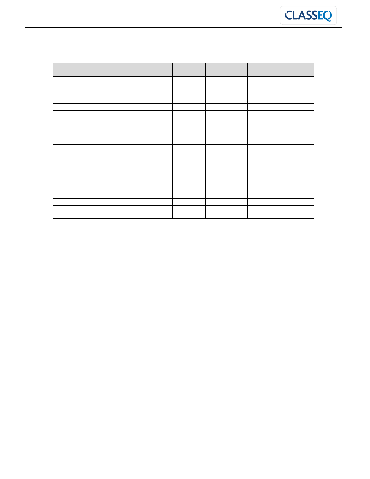
Machine dimensions:
Dishwashers
CST
With dyer
Machine
(mm)
A = width
(mm)
1300
2000
B = depth
Closed (mm)
810
Open (mm)
1490
C = height
(mm)
1380-1440
1730-1790
Basket size (mm) (square basket)
500
Load capacity (dishes)
18
Load capacity (pint glass)
30
Basket rate (Baskets/hour)
100 / 130
Rinse running water temperature
82°C
Rinse standby water temperature
60°C
Wash water temperature
55°C
B C A
B

ENGINEERS MANUAL CST MACHINES AND DRYER UNIT
Drawn up: 05/10/2018
Document number : 30008893
Page 11 of 48
Revision: C
Electric Supply:
Electrical connection:
Electrical connections MUST be carried out by an authorized technician and in accordance with local
and national regulations.
As a minimum Classeq recommends the following standards are maintained:
All appliances are connected via a residual current device (R.C.D.) or earth leakage protection device.
EN60204:
Supply isolator switch has all pole separation of more than 3mm.
EN60335:
Connect to an equi-potential conductor, connection stud located at bottom of the appliance to the rear;
this is in addition to the earthed electrical supply.
Prior to connecting the appliance, ensure voltage and supply fuse comply with rating plate.
Electrical rating:
Note: Electrical supply can be
either side of the appliance. The
appliance not supplied with the
electrical plugs.
If the supply cable is damaged ,
it must be replaced by a cable or
cord assembly supplied by
Classeq or its service agents or
to the following minimum
specification.
Cable type
Temperature
rating
Length of cable
Confirm to /
standard
H07RN-F
5G10
80°C minimum
5m
IEC 60335-2-58
&
IEC 60227 types
56 & 57
Electrics
CST
Dryer unit
Volts
380 – 415V (3
Phase)
380 – 415V (3
Phase)
Amps
Hot fill
32A per phase
+12A per phase
Cold Fill
45A per phase
Max total load
Hot fill
13.74kW
+4.5kW
Cold Fill
25.74kW

ENGINEERS MANUAL CST MACHINES AND DRYER UNIT
Drawn up: 05/10/2018
Document number : 30008893
Page 12 of 48
Revision: C
Water Inlet and Waste out let:
Water connection:
The appliance comes with a water supply hose requiring
a G¾” (¾” BSP) male threaded connection at the mains
water supply, upon installation and commissioning all
water joints must be checked for leaks.
Old existing, defective or damaged water supply hoses
are NOT to be used when installing the appliance.
Commercial appliance wash results will be affected by
external conditions such as incoming water
temperature, pressure, harness and choice of
chemicals.
For the longevity of any water related devices and to
ensure you get consistently good results it is essential your machine is either fed from a soft water
supply , or your Classeq appliance is connected to an appropriate water softener.
Note: Water supply can be either side of the machine.
IMPORTANT:
All supplier warranties are void if lime scale is present within an appliance
If the above requirements are not adhered to, the performance of the appliance will be impaired
CST 100 / 130
Temperature range
5-55°C
Pressure
0~2 bar
Booster pump required
2~4 bar
No modification
4~6 bar
Flow restrictor required
6 bar +
Pressure reducing valve
required
Flow rate
4.7 Lts / min
Water connection
G ¾” (¾” BSP)
Inlet valve
Waste outlet / Drain hose

ENGINEERS MANUAL CST MACHINES AND DRYER UNIT
Drawn up: 05/10/2018
Document number : 30008893
Page 13 of 48
Revision: C
Waste outlet:
The CST is a gravity drain machine, upon installation the
waste must be configured as stated in this manual.
All installations should be fitted with a running ‘P’ trap to
ensure hygiene.
Ø40mm (1 ½”) standpipe required, must be lower than
the baseline of the wash tank.
Drain hose must be a close / tight fit into the drain pipe
to reduce odours from the drain system.
To ensure correct drainage, the height the sites drain is from the floor / surface the machine sits
upon MUST be within the following
Waste hose must flow down from the waste outlet to the drain.
Joint between standpipe and waste hose must be water tight.
If you have any doubts about the drainage system on the machine, please contact either Classeq or
your dealer/agent.
Terminal block layout
Terminal block (TB1) configuration (Mains supply):
Drainage dimensions
(mm)
CST
Drain stand pipe diameter
Ø40
Maximum drain pipe
height (Gravity drain)
(Depending on height
adjustment)
270 - 330mm
4mm² wires for heating
10mm² incoming mains cable
0.75mm² cable to pumps
0.5mm² neutral cable to Filter
4A
1.5mm² cable to control
harness and pumps
1.5mm² earth cable
0.75mm² cable to dryer
unit (if fitted)

ENGINEERS MANUAL CST MACHINES AND DRYER UNIT
Drawn up: 05/10/2018
Document number : 30008893
Page 14 of 48
Revision: C
8. Commissioning Instructions
Rinse aid & Detergent:
The CST is not fitted with internal chemical dosing pumps, these will need to be fitted during the
installation.
A terminal block is provided on right hand side of the wash tank for connecting the electrics of the
chemical pumps.
Note: Isolate the machine prior to the access and connection of the chemical pump terminal block.
WARNING: Only rinse aids and detergents developed for commercial glass and
dishwashers are to be used, rinse aids must be suitable for water temperatures down to
40°C.
Terminal block configuration (Chemical pumps):
Yellow/green
Blue
orange
Purple
Brown
Earth
Neutral
Running
WT full
Live

ENGINEERS MANUAL CST MACHINES AND DRYER UNIT
Drawn up: 05/10/2018
Document number : 30008893
Page 15 of 48
Revision: C
Machine temperature settings:
The water temperatures on ’Classeq’ range of machines are adjustable, but have been pre-set to:
Thermostat positions
Rinse thermostat –
standby (ST1)
Rinse thermostat –
Running (ST2)
Wash thermostat
(ST3)
60ºC
82ºC
55ºC – 60°C
Dryer temperature setting
The air temperature on the ’Classeq’ dryer range is adjustable, but have been pre-set to:
Dryer air temperature
(ST4)
60ºC
The manual reset safety thermal trips on the machine are set to the following values and cannot be
adjusted:
Wash tank – 85°C
Rinse boiler – 95°C
Air blower – 85°C
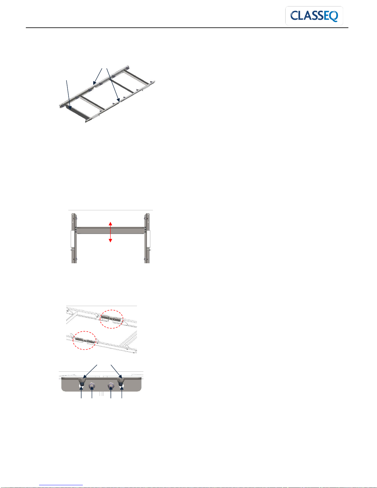
Table end limit switch
It is very important that the table end limit switch be installed at the end of the exit table and the arm
adjusted so that it is activated by the basket before it reaches the end of the table. The cable should
be routed through the small cable gland at the rear of the machine and plugged into the harness at the
connector near the small terminal block. The switch should be wired on the normally closed circuit.

ENGINEERS MANUAL CST MACHINES AND DRYER UNIT
Drawn up: 05/10/2018
Document number : 30008893
Page 16 of 48
Revision: C
This switch will stop the machine when activated allowing the operator time to remove the clean
baskets before more baskets are pushed through the machine.
Min. 50mm
Adjustable 20-70mm
Cable gland
Terminal
block

ENGINEERS MANUAL CST MACHINES AND DRYER UNIT
Drawn up: 05/10/2018
Document number : 30008893
Page 17 of 48
Revision: C
Electrical supply setup
If the machine is fitted to a hot water supply (maximum temperature of 55°C) then the electrical supply
to the machine can be changed (►7). This is done by turning off CB2, this turns off one of the banks
of elements used in the rinse boiler and reduces the current required.
Cold fill (45A per phase)
Hot fill (32A per phase)
Installing the splash guard (only if not dryer fitted)
Once the machine has been installed and all tabling has been aligned the splash guards should be
fitted to the exit of the machine.
Remove the 3x M5 screws on either side of the exit and use these to fasten the splash guard in place.
Align the splash guard to the front of the machine and the side of the exit as best as possible. Once
fitted the splash guards should be sealed against the tabling.
CB2 OFF
CB2 ON

ENGINEERS MANUAL CST MACHINES AND DRYER UNIT
Drawn up: 05/10/2018
Document number : 30008893
Page 18 of 48
Revision: C
9. Water Systems
Rinse system (Also used for filling the wash tank):
Wash system:
ENGINEERS MANUAL CST MACHINES AND DRYER UNIT
Drawn up: 05/10/2018
Document number : 30008893
Page 19 of 48
Revision: C
10. Electrical Component Data
Component
Voltage
(V)
Frequancy
(Hz)
Current
(A)
Power
(W)
Resistance
(Ω)
Inlet solenoid
valve
220 ~ 240
50 ~ 60
- - -
Rinse elements
4 x (3x2kW)
230
50 ~ 60
8.7 / leg
2000 / leg
26.42 / leg
Wash elements
2 x (3x2kW)
230
50 ~ 60
8.7 / leg
2000 / leg
26.42 / leg
Rinse pump
220 ~ 240
50
1.2 (Running)
250
Wash pump
380 ~ 415
50
2.8
1100
Drive motor
380 ~ 415
50
1.23
370
Contactors
220 ~ 240
50
Timer
220 ~ 240
50
Relays - (Finder)
220 ~ 240
50
Indicator lamps
White (LED)
220 ~ 240
50 ~ 60
Amber
220 ~ 240
50 ~ 60
Blue
220 ~ 240
50 ~ 60 Red
220 ~ 240
50 ~ 60
Air pressure
switches
220 ~ 240
50 ~ 60
Temperature
display
220 ~ 240
50 ~ 60
Blower unit
380 ~ 415
50
1.05
500
Air heater
element
3x 2kW
230
50 ~ 60
8.7
2000
26.42

ENGINEERS MANUAL CST MACHINES AND DRYER UNIT
Drawn up: 05/10/2018
Document number : 30008893
Page 20 of 48
Revision: C
11. Changing orientation
CST is designed to allow adaption to a change in direction of travel during the commissioning of the
machine.
Ensure the machine is fully drained prior to commencing any changes.
Remove all the curtains and the cassette assembly from the machine.
Danger
For safety reason turn
off all electrical
supplies to your
machine before
following these steps.
Remove rear top and rear bottom panels in order to get access to wash and rinse hoses.
When changing the direction of the CST care must be taken not to misplace or damage the sealing Orings.
11.1 Changing wash and rinse arms system.
Remove the wash arms and cassette from the machine.
Remove wash arm brackets and fixing tubes. Take note shorter fixing tubes used at bottom and
longer fixing tube used at top.
Remove rinse arm hose from rinse bush.
Remove rinse arms and associated brackets.
Loosen and remove the top wash manifold.
Remove the blanking covers from the remaining holes
Loosen the jubilee clips for the bottom wash manifold.
Rotate the bottom wash manifold 180° to the new position and fasten using long fixing tubes.
C= CST Middle wash hose
C

ENGINEERS MANUAL CST MACHINES AND DRYER UNIT
Drawn up: 05/10/2018
Document number : 30008893
Page 21 of 48
Revision: C
Tighten jubilee clips
Replace wash top wash hose with the hose required for the direction of travel.
Fit top manifold and wash arm. Fasten into place using short fixing tubes and tighten jubilee clips.
Fit rinse arms into outer most holes. Align holes to face directly vertical and fasten into place.
Fit rinse hose to rinse bushes and tighten jubilee clips.
Fit blanking covers into remaining holes.
Fit rinse and wash arm brackets. Note fixing ring orientation.
Fit wash arms.
Move curtain bracket to front edge of entry side of machine (►5).
The below image shows the orientation of the wash arms, rinse arms and blanking covers for both
directions of travel.
Caution
Classeq recommend that
any changes to the
machine be carried out by
trained field technician.
A B
A= Right hand CST Top wash hose
(PN)
B= Left hand CST Top wash hose
(PN)
Wash
Rinse
Blanking
Right to left
Left to right
ENGINEERS MANUAL CST MACHINES AND DRYER UNIT
Drawn up: 05/10/2018
Document number : 30008893
Page 22 of 48
Revision: C
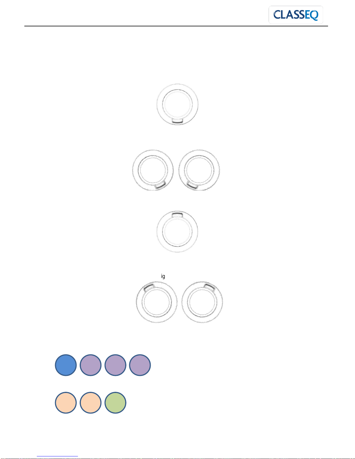
11.2 Setting orientation of the wash arms
Note the orientation of the locating ring for the wash arms. These are fitted in different orientations in
the machine as show below
Orientation 1:
Pointing directly down
Orientation 2:
Tilted slightly inward from entrance
Orientation 3:
Pointing directly up
Orientation 4:
Tilted slightly outward towards entrance
The above orientations are used in the assembly of the wash arms as below:
Top wash arms shown with entrance to the left:
Bottom wash arms shown with entrance to the left:
Left to right Right to left
Left to right Right to left
2 1 1
1
3 3 4
ENGINEERS MANUAL CST MACHINES AND DRYER UNIT
Drawn up: 05/10/2018
Document number : 30008893
Page 23 of 48
Revision: C
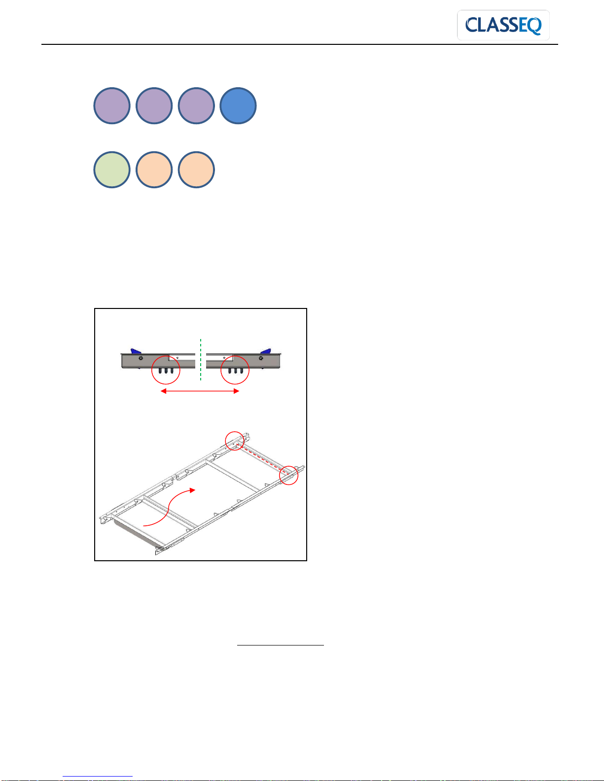
Top wash arms shown with entrance to the right:
Bottom wash arms shown with entrance to the right:
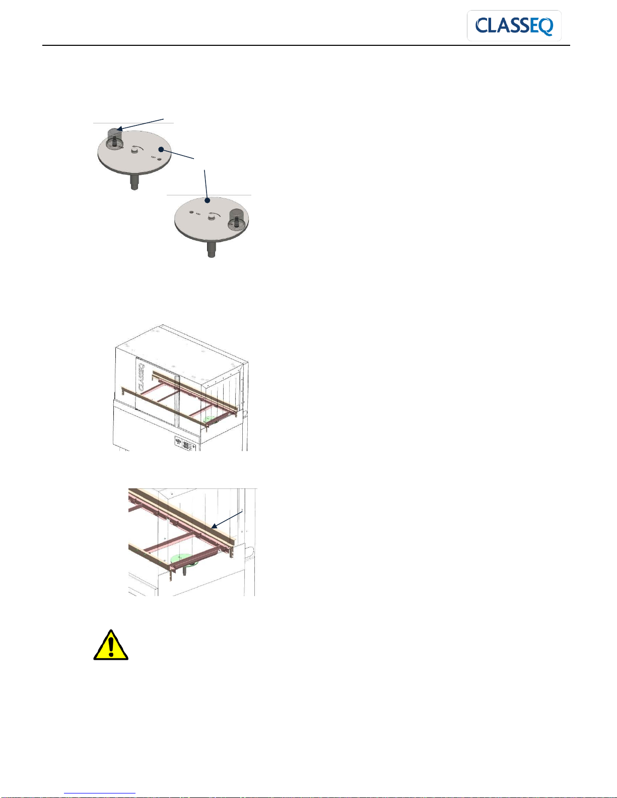
11.3 Changing cassette assembly setting.
Once CST’s hoses have been changed, the cassette assembly needs to be rotated to move the
baskets in the required direction.
Remove the nuts holding centre plate.
Relocate the centre plate to opposite side of cassette assembly and fasten it with nuts. Ensure centre
plate is fitted to the correct speed setting (►10).
Place cassette assembly back into machine and fasten into place with the fixing screws.
Fit the curtains back into machine
Turn on all electrical supplies to your machine.
Damage to the machine caused by failure to follow steps will NOT be covered by the Manufacturer’s
Warranty.
Symmetric
℄
1 1 1 2 4 3 3
ENGINEERS MANUAL CST MACHINES AND DRYER UNIT
Drawn up: 05/10/2018
Document number : 30008893
Page 24 of 48
Revision: C
12. Speed setting
F = 1 x Centre plate
G = 2 x Speed variable plate
The CST is available at two speed settings of 100 or 130 baskets per hour. In order to change the
setting, remove cassette assembly from the machine and follow the steps below:
Step 1: Remove 4x M5 nuts holding centre plate (F) then re-locate centre plate (F) to the correlating
stud and tighten it back with the 4 x M5 nuts.
Step 2: Loosen the 2 nuts attached to the slot of speed adjustment plate (G) on each side. Then
remove socket button head screws (M5x12) and M5 nuts from the hole and re-locate it to required
speed hole of symmetrically on each side.
F
130
100
100
130
Nuts
100
130
130
100
G
ENGINEERS MANUAL CST MACHINES AND DRYER UNIT
Drawn up: 05/10/2018
Document number : 30008893
Page 25 of 48
Revision: C
Step 3: Remove bolt attaching rotating cap (I) to drive plate (J) in the machine and re-locate rotating
cap (I) to require speed setting onto drive plate (J) and tighten the bolt.
I = Rotating cap
J = Drive plate
Step 4: Place cassette assembly back into the machine as follow. Ensure centre plate (F) fits onto
rotating cap (I) and plastic guides (H) sit into the drive rail (K) properly.
K = Drive rail
Caution
It is very important to follow the
steps; failure to it will lead to
potential damage to the cassette
assembly.
If in doubt then contact Classeq or your local dealer.
I J K

ENGINEERS MANUAL CST MACHINES AND DRYER UNIT
Drawn up: 05/10/2018
Document number : 30008893
Page 26 of 48
Revision: C
13. Setting basket arm
The basket arm is factory set to work with all Classeq baskets and should not need to be adjusted.
However should baskets from a different manufacturer be used that is not being picked up by the
machine or are causing the machine to stop in the cylce then the arm can be adjusted to suite these.
At the right hand side of the basket arm is a bracket to allow for adjustment.
1. Isolate the machine.
2. Insert the off sized basket into the centre of the machine
3. Remove the M3 screw and nylock nut.
4. Rotate the magnet arm so that the hooked end is in line with the bend in the cabinet.
5. Find a matching pair of holes for the fastener and tighten in place.
6. Turn on machine, fill and test operation. Readjust if required.

ENGINEERS MANUAL CST MACHINES AND DRYER UNIT
Drawn up: 05/10/2018
Document number : 30008893
Page 27 of 48
Revision: C
14. Machine wiring and layout
Machine control panel layout
Rinse heater contactors
(CT1 & CT2)
Wash heater contactors
(CT3 & CT6)
Rinse heater contactors
(CT4 & CT5)
Three phase
breakers (1-3) 25A
Three phase
breaker (4) 6A
Breaker (5) 6A
Timer (TM1)
On/Off relay (RL1)
Door relay (RL2)
Wash pump relay (RL3)
Machine full relay (RL4)
Basket present relay (RL5)
Drive motor relay (RL6)
Wash heater relay (RL7)
Timer (TM2)
Control Panel
RC Filter
Timer (TM3)

ENGINEERS MANUAL CST MACHINES AND DRYER UNIT
Drawn up: 05/10/2018
Document number : 30008893
Page 28 of 48
Revision: C
Front panel
Z
On/Off switch
On/Off lamp (L1)
Double
Red
Double
Blue
Pump running lamp (L2)
Heating lamp (L3)
Error lamp (L4)
Purple
Brown
Double
Blue
Double
Blue
Brown
Brown
Double
Blue
Orange
L
N
Wash temperature
Double
Double
L
N
Rinse temperature
Double
Double
Orange
Brown

ENGINEERS MANUAL CST MACHINES AND DRYER UNIT
Drawn up: 05/10/2018
Document number : 30008893
Page 29 of 48
Revision: C
Machine breakers and timer wiring
Type
Breaker
size
Breaker
number
Wire colour / Connection configuration
6A
Circuit
breaker 5
Incoming wire from Filter 4A (P1)
Out going wire to On/Off switch
6A
Breaker 4
(3 phase
breaker)
Incoming wire from Terminal block (TB1)
Out going wire to Drive motor relay (RL6)
Incoming wire from Terminal block (TB1)
Out going wire to Drive motor relay (RL6)
Incoming wire from Terminal block (TB1)
Out going wire to Drive motor relay (RL6)
25A
Breaker 1
Incoming wire from terminal block (TB1)
Out going wire to heating contactor (CT1)
Incoming wire from Terminal block (TB1)
Out going wire to heating contactor (CT1)
Incoming wire from Terminal block (TB1)
Out going wire to heating contactor (CT1)
Breaker 2
Incoming wire from Terminal block (TB1)
Out going wire to heating contactor (CT2)
Incoming wire from Terminal block (TB1)
Out going wire to heating contactor (CT2)
Incoming wire from Terminal block (TB1)
Out going wire to heating contactor (CT2)
Breaker 3
Incoming wire from Terminal block (TB1)
Out going wire to heating contactor (CT3)
Incoming wire from Terminal block (TB1)
Out going wire to heating contactor (CT3)
Incoming wire from Terminal block (TB1)
Out going wire to heating contactor (CT3)

ENGINEERS MANUAL CST MACHINES AND DRYER UNIT
Drawn up: 05/10/2018
Document number : 30008893
Page 30 of 48
Revision: C
Motor timer (TM1)
A2
Neutral from Terminal block (TB1)
A1
From timer (TM2)
B1
Incoming wire from Door relay (RL2)
18
To Drive motor (DM1)
15
Incoming wire from Door relay (RL2)
Time segment
Select time
segment to
be used
Default:
2m (2 minutes)
Time
Adjust time
within time
segment
Default:
20 (Full)
Timer type
Select type
of timer
Default:
BE (On delay)
DO NOT CHANGE
Delay timer (TM2)
A2
Neutral from Terminal block (TB1)
A1
Incoming wire from Door relay (RL2)
B1
Incoming wire from Basket switch
(Sw4)
18
To Basket pressent relay (RL5)
15
From timer (TM2)
Time segment
Select time
segment to
be used
Default:
2m (2 minutes)
Time
Adjust time
within time
segment
Default:
10 (Half)(1 minute)
Timer type
Select type
of timer
Default:
BE (On delay)
DO NOT CHANGE

ENGINEERS MANUAL CST MACHINES AND DRYER UNIT
Drawn up: 05/10/2018
Document number : 30008893
Page 31 of 48
Revision: C
Delay timer (TM3)
A2
Neutral from Terminal block (TB1)
A1
From CB5
B1
From on/off switch
18
To Basket pressent relay (RL5)
16
To Control circuit
15
From timer (TM2)
Time segment
Select time
segment to
be used
Default:
20s (20 seconds)
Time
Adjust time
within time
segment
Default:
5 (Quarter)(5 Seconds)
Timer type
Select type
of timer
Default:
BE (On delay)
DO NOT CHANGE

ENGINEERS MANUAL CST MACHINES AND DRYER UNIT
Drawn up: 05/10/2018
Document number : 30008893
Page 32 of 48
Revision: C
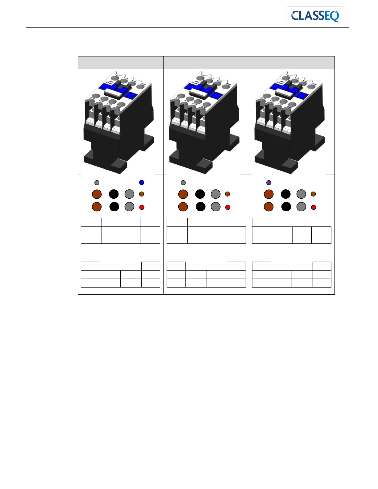
Machine contactors
Rinse heating contactor (CT1)
Rinse heating contactor (CT2)
Wash heating contactor (CT3)
Red
Blue
Brown
Black
Grey
Brown
Black
Grey
Red
Blue
Brown
Black
Grey
Brown
Black
Grey
Red
Blue
Brown
Black
Grey
Brown
Black
Grey
A1
A2
2T1
4T2
6T3
14NO
1L1
3L2
5L3
13NO A1
A2
2T1
4T2
6T3
14NO
1L1
3L2
5L3
13NO A1
A2
2T1
4T2
6T3
14NO
1L1
3L2
5L3
13NO
ENGINEERS MANUAL CST MACHINES AND DRYER UNIT
Drawn up: 05/10/2018
Document number : 30008893
Page 33 of 48
Revision: C
Machine contactors
Rinse heating contactor (CT4)
Rinse heating contactor (CT5)
Wash heating contactor (CT6)
Grey
Blue
Brown
Black
Grey
Brown
Brown
Black
Grey
Red Grey
Brown
Black
Grey
Brown
Brown
Black
Grey
Red Purple
Brown
Black
Grey
Brown
Brown
Black
Grey
Red
A1
A2
2T1
4T2
6T3
14NO
1L1
3L2
5L3
13NO
A1
A2
2T1
4T2
6T3
14NO
1L1
3L2
5L3
13NO
A1
A2
2T1
4T2
6T3
14NO
1L1
3L2
5L3
13NO

ENGINEERS MANUAL CST MACHINES AND DRYER UNIT
Drawn up: 05/10/2018
Document number : 30008893
Page 34 of 48
Revision: C
Machine relays
Wash heater Relay (RL7)
Door Relay (RL2)
Wash pump Relay (RL3)
Red cover
Black cover
White cover
Green cover
Purple
Purple
Red
Blue
White
Black
Orange
Red
Purple
Purple
Brown
Orange
Blue
Black
Grey
Grey
Black
Purple
Purple
Grey
Blue
22
32
24
34
21
31
12
14
11
A1
A2
22
32
24
34
21
31
12
14
11
A1
22
32
24
34
21
31
12
14
11
A1
A2
Normally closed
Normally open
Common
Coil
A2
Red cover
Black cover
White cover
Green cover
ENGINEERS MANUAL CST MACHINES AND DRYER UNIT
Drawn up: 05/10/2018
Document number : 30008893
Page 35 of 48
Revision: C
Machine relays
Machine full Relay (RL4)
Basket present Relay (RL5)
Drive motor Relay (RL6)
Machine relays
ON / OFF Relay (RL1)
Purple
Purple
Brown
Blue
White
Grey
Orange
Black
Black
Brown
Brown
White
Blue
Black
Grey
Grey
Black
Purple
White
White
Blue
Red
White
22
32
24
34
21
31
12
14
11
A1
A2
22
32
24
34
21
31
12
14
11
A1
22
32
24
34
21
31
12
14
11
A1
A2
Normally closed
Normally open
Common
Coil
A2
Red cover
Black cover
White cover
Green cover
Red cover
Black cover
White cover
Green cover
Blue
Brown
White
From SW3
From CB5
To control unit
ENGINEERS MANUAL CST MACHINES AND DRYER UNIT
Drawn up: 05/10/2018
Document number : 30008893
Page 36 of 48
Revision: C
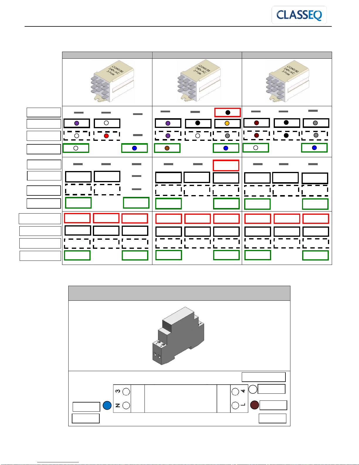
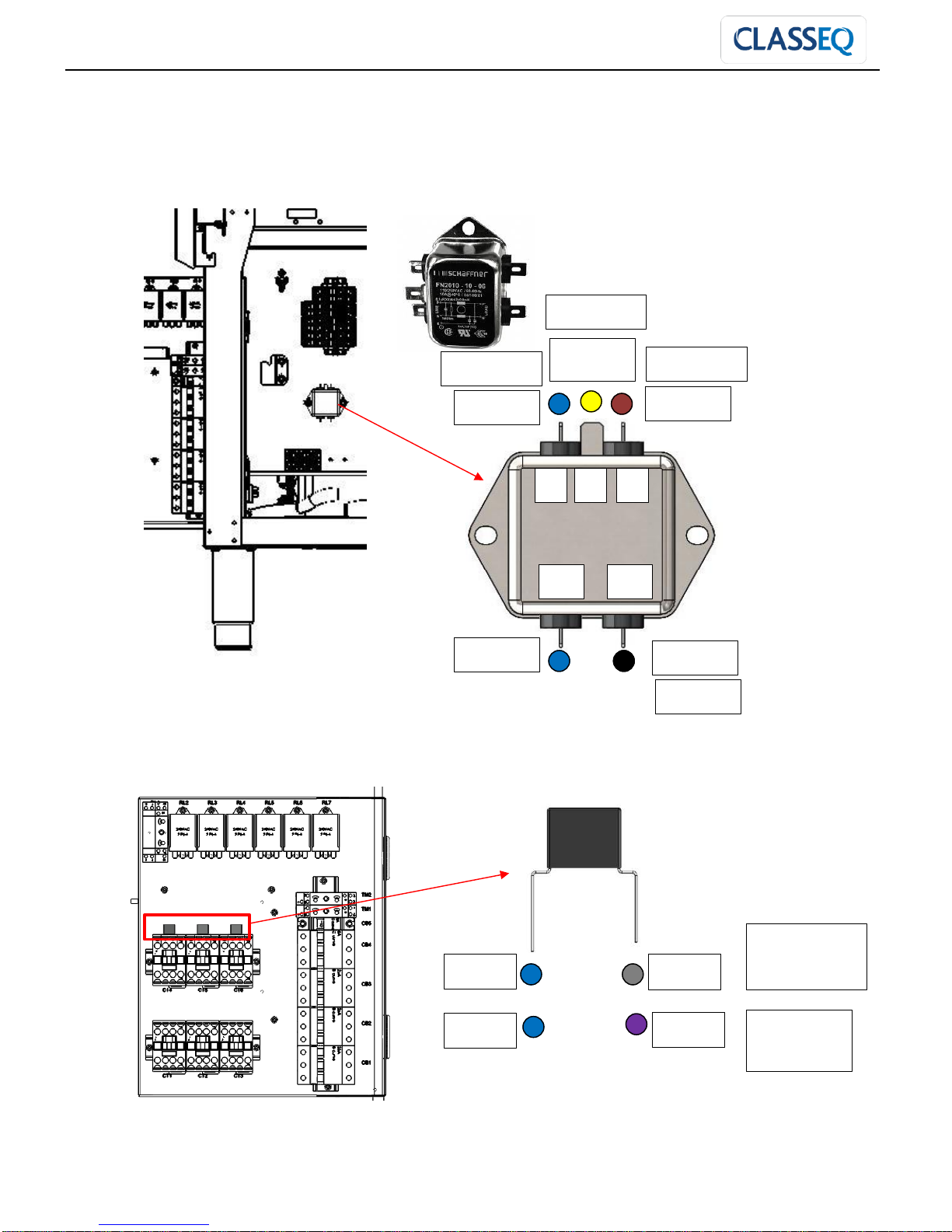
Machine Filters
1) Suppression filter (4 Amp)
2) RC Filters
Brown
Blue
Black
Blue
P
P1
N1
N
E
Yellow -
Earth
CT4 & CT5
Rinse heating
contactor
CT6 Wash
heating
contactor
Grey
Purple
Blue
Blue
To CB5
From TB1
From TB1
From TB1
ENGINEERS MANUAL CST MACHINES AND DRYER UNIT
Drawn up: 05/10/2018
Document number : 30008893
Page 37 of 48
Revision: C
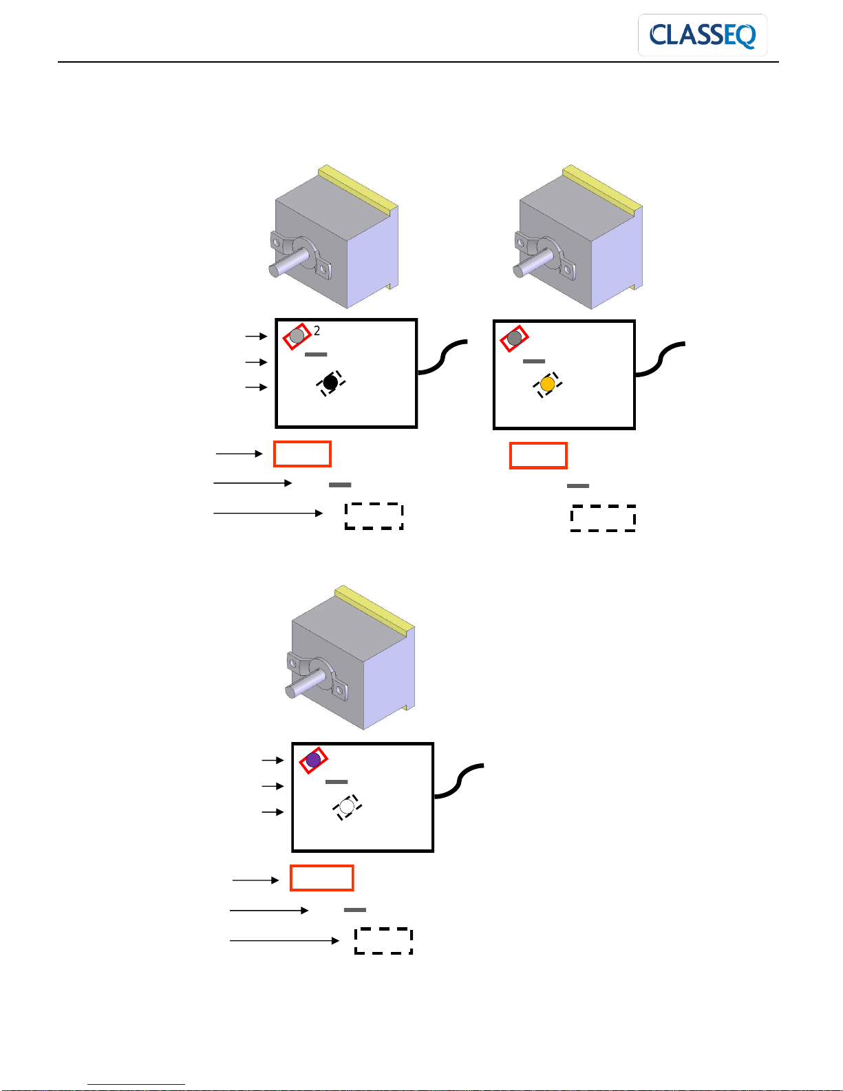
Machine thermostat wiring
Rinse standby thermostat (ST1) Rinse run thermostat (ST2)
Wash thermostat (ST3)
Grey
Orange
2 1 2
Grey
Black
Red cover / Normally Closed
Black cover / Normally Open
White cover / Common
1
Red cover
Black cover
White cover
Red cover
Black cover
White cover
2
1
Red cover / Normally Closed
Black cover / Normally Open
White cover / Common
Purple
White
ENGINEERS MANUAL CST MACHINES AND DRYER UNIT
Drawn up: 05/10/2018
Document number : 30008893
Page 38 of 48
Revision: C
Machine options / Selection
Table end switch (CC4 and CC5) connector plug
Basket present switch (SW4) connector plug
Motor clutch switch (SW2) connector plug
Door switch (SW3) connector plug
Purple
Black
Grey
Blue
Brown
Red
Red
Red
Brown
Red
Grey
Red
Brown
Common
Air break
Pressurised
Purple
Brown
Brown
Grey
Red
White

ENGINEERS MANUAL CST MACHINES AND DRYER UNIT
Drawn up: 05/10/2018
Document number : 30008893
Page 39 of 48
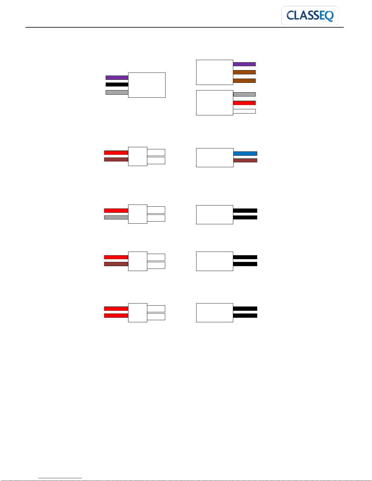
Revision: C
Note: Connect capacitor terminals with
the wires coming from Rinse pump
Components wiring
Component
Part number &
Description
Wiring configuration
Inlet Solenoid Valve
Rinse safety
Thermostat (95°C)
Wash safety
Thermostat (85°C)
Wash Air
pressure Switch
Rinse Air
pressure Switch
Rinse Pump
Wash pump
Drive motor
11 / 14 / 12 22 / 24 / 21
Purple Black
Blue Wire
White Crimp
Grey wire
White Crimp
Blue Wire
White Crimp
Double blue Wire
White Crimp
Blue Wire
White Crimp
Double blue Wire
White Crimp
11 / 14 / 12 22 / 24 / 21
Grey Red
Red Brown
U1
V1
W1
U1
V1
W1
Purple
Black
Grey
Brown
Black
Grey
Brown
Blue
D Purple
Blue
Brown White
ENGINEERS MANUAL CST MACHINES AND DRYER UNIT
Drawn up: 05/10/2018
Document number : 30008893
Page 40 of 48
Revision: C
Element wiring
6kW Rinse elements, using LM-CST-HEATING
Element 1, 2, 3 & 4:
6kW Wash elements, using LM-CST-HEATING
Element 5 & 6:
Temperature probes:
Brown wire (Thick)
Black wire (Thick)
Grey wire (Thick)
Brown wire (Thick)
Black wire (Thick)
Grey wire (Thick)
Temperature gauge
Running temperature:
82-85 degrees
Standy Temperature:
55-58 degrees

ENGINEERS MANUAL CST MACHINES AND DRYER UNIT
Drawn up: 05/10/2018
Document number : 30008893
Page 41 of 48
Revision: C
15. Dryer unit wiring and layout
Dryer control panel layout
Tempraure rdfd
Air heater relay (RL8)
Heater safety relay (RL9)
Blower relay (RL10)
Dryer breaker (CB6)

ENGINEERS MANUAL CST MACHINES AND DRYER UNIT
Drawn up: 05/10/2018
Document number : 30008893
Page 42 of 48
Revision: C
Dryer terminal block (TB3)
Earth
1.5mm
Black
0.5mm
Orange
0.5mm
White
0.5mm
Grey
0.75mm
Black
0.75mm
Brown
0.75mm
White
1.5mm
Purple
1.5mm
Brown
1.5mm

ENGINEERS MANUAL CST MACHINES AND DRYER UNIT
Drawn up: 05/10/2018
Document number : 30008893
Page 43 of 48
Revision: C
Blower terminal block
From TB3
From thermal
safety trip
To TB3
From TB3
Brown
Black
Grey
White
Red
Earth
Linked
1 2 3 4 5 6 7 8 9
10
11
12
13
14
15
Blue
Brown
Black
White
White
Earth
Red
Grey
Orange
To blower motor
Dryer breakers
Type
Breaker
size
Breaker
number
Wire colour / Connection configuration
16A
Breaker 6
(3 phase
breaker)
Incoming wire from Terminal block (TB3)
Out going wire to Drive motor relay (RL8)
Incoming wire from Terminal block (TB3)
Out going wire to Drive motor relay (RL8)
Incoming wire from Terminal block (TB3)
Out going wire to Drive motor relay (RL8)

ENGINEERS MANUAL CST MACHINES AND DRYER UNIT
Drawn up: 05/10/2018
Document number : 30008893
Page 44 of 48
Revision: C
Dryer relays
Air heater relay (RL8)
Heater safety relay (RL9)
Blower relay (RL10)
Dryer thermostat
Red cover
Black cover
White cover
Green cover
Brown
Brown
Black
Blue
Purple
White
White
Purple
Brown
Brown
Black
Blue
Black
Grey
Grey
Black
Brown
Brown
Orange
Blue
Grey
White
22
32
24
34
21
31
12
14
11
A1
A2
22
32
24
34
21
31
12
14
11
A1
22
32
24
34
21
31
12
14
11
A1
A2
Normally closed
Normally open
Common
Coil
A2
Red cover
Black cover
White cover
Green cover
Orange
White
1
Red cover
White cover
2
Purple
Black

ENGINEERS MANUAL CST MACHINES AND DRYER UNIT
Drawn up: 05/10/2018
Document number : 30008893
Page 45 of 48
Revision: C
Dryer safety thermostat
Rinse safety
Thermostat (100°C)
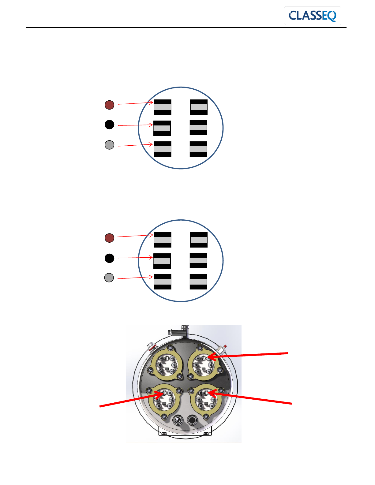
Dryer elements
6kW Delta connection
Red Wire
White Crimp
Black Wire
White Crimp
Dryer Element 2 (E8)
Dryer Element 1 (E7)
White wire
from TB3
Purple wire
from TB3
Brown wire
from TB3
Black wire
Brown wire
Grey wire

ENGINEERS MANUAL CST MACHINES AND DRYER UNIT
Drawn up: 05/10/2018
Document number : 30008893
Page 46 of 48
Revision: C
16. Trouble shooting
I. Machine does not fill:
Check water supply is turned ON.
Check water supply hose is not trapped or kinked.
Check that the machine is switched ON.
Check that door is closed.
Check table end switch has not been activated.
Check there is no obstruction around the drive plate or cassette.
Check that the air pressure switches are switched correctly (see wiring diagram)
Check solenoid valve and rinse pump are getting powered up.
II. Cycle does not start:
Check that the machine is switched ON.
Check wash tank is full.
Check that the error lamp is not illuminated.
Check basket arm rod touching the basket.
Check water supply is turned ON.
Check water supply hose is not trapped or kinked.
Check that the rinse boiler is full.
Check that breaker 4 and 5 are both on.
III. Machine fills slowly:
Check water supply tap is fully open.
Check water supply hose is not trapped or kinked.
Check water supply pressure and remove any pressure regulator or reducer.
Check and clean rinse jets (located on the rinse arms within the machine).
Check drain plug securely fitted and sealing.
Check the correct flow restrictors are fitted:
o Purple (4l/min) in rinse hose
o Orange (8l/min) in solenoid
IV. Machine not heating:
Check machine is ON.
Ensure enough time has been allowed for machine to reach correct temperatures.
Check that the machine is full of water.
Check that breaker 3 is ON.
Check breaker 1 and 2 are on as relivent.
V. Machine not draining:
Check and clean all filters within the machine.
Check that the drain is not clogged / blocked / kinked.
Check waste hight is below the base of the machine.
VI. Poor wash results:
Check and replenish chemicals.
Ensure chemical dosing is corect.
Check and clean wash and rinse jets on the wash and rinse arm assemblies.
Clean filters within machine and check that they are fitted correctly.
Check water supply is ON and fully open.
Rinse dishes of food debris before placing into the dishwasher.

ENGINEERS MANUAL CST MACHINES AND DRYER UNIT
Drawn up: 05/10/2018
Document number : 30008893
Page 47 of 48
Revision: C
VII. Overfilling:
Drain machine fully, then try again to fill the machine.
Check and clean all filters within the machine.
Check drain height is configured correctly.
Check that drain is not clogged / blocked / kinked.
Check and clean drain plug.
Check wash APS is switching correctly.
VIII. Wash water foaming:
Check chemicals are manufactured for use in commercial dishwashers.
Check wash water is up to temperature.
Check chemical dosing is set according to the chemical manufacturers requirements.
Check wash tank thermal trip.
Drain, refill and allow re-heating.
IX. Will not turn ON:
Check and reset circuit breaker within the sites fuse board.
Check and reset breaker 5.
Check on/off relay (RL1).
X. Basket not moving:
Check for obstructions on the drive rail and at the drive plate.
Check cassette is fitted correctly and flat.
Check that machine error lamp is not illuminated.
Check breaker 4 is ON.
Check both timers are opperating.
Check drive motor relay (RL5).
XI. Machine stopping and starting while in a cycle:
Check water supply hose is not trapped or kinked.
Check water supply tap is fully open.
Check dynamic water pressure is above 2 bar.
Check table end switch has not been activated.
Check the correct flow restrictors are fitted:
o Purple (4l/min) in rinse hose or Fitted Flow restrictor
o Brown (5l/min) in solenoid
Check over run timer (TM2) is set and working correctly.
XII. Red (Error) lap illuminated:
Check door is closed.
Check driving cassette is not jammed.
Check table end switch has not been activated.
XIII. Blower unit not blowing air:
Check blower wiring.
Check dryer unit breaker (6).
XIV. Dryer not heating air:
Check dryer unit breaker (6).
Check dryer heater thermal trip.

ENGINEERS MANUAL CST MACHINES AND DRYER UNIT
Drawn up: 05/10/2018
Document number : 30008893
Page 48 of 48
Revision: C
Classeq Ltd
Winterhalter House
Roebuck Way
Knowlhill
Milton Keynes
MK5 8WH
Spares department
0844 225 9252
spares@classeq.co.uk
Service department
0844 225 9245
service@classeq.co.uk
Classeq Ltd
 Loading...