


Installation
Installation
&&
Operators Manual
Operators Manual
C200G, C300G
C200G, C300G
C500U, C750U & C850P
C500U, C750U & C850P
Part number 902.0002
Revision C
DISHWASHERS, COMMERCIAL
51GA

Installation and Operation instructions
Installation and Operation instructions
For ‘Classeq Inc.’ under counter range of glass and dishwashers.
Section Title Page(s)
1
Safety instructions
1
2
The appliance
1
3
Installation
2 - 4
4
Commissioning
4 - 5
5
Operation
6 - 7
6
Cleaning
8
7
Trouble shooting
8 - 10
LM-C200G
Wiring diagram - C200G & C500U
11
LM-C750U
Wiring diagram - C300G & C750U
12
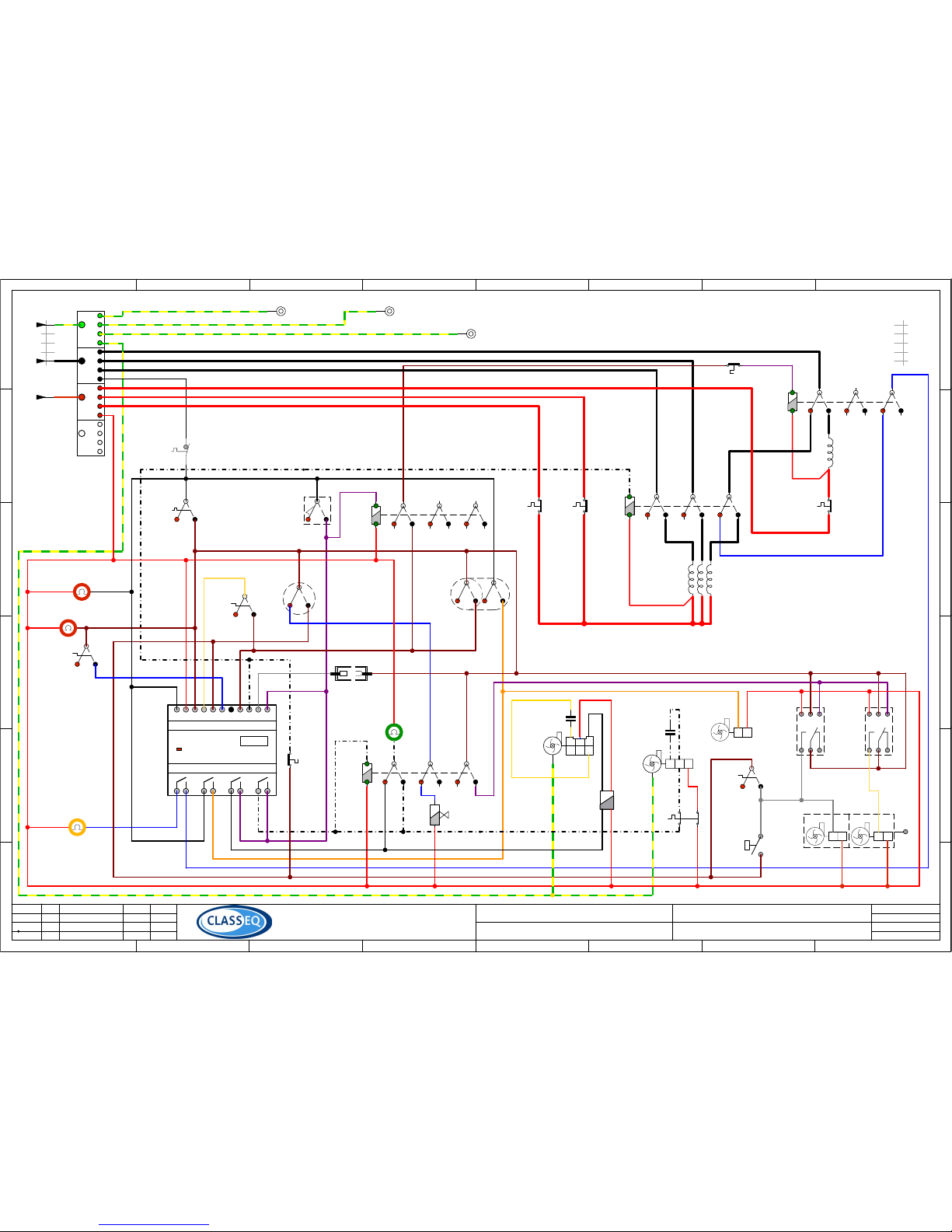
LM-C850P
Wiring diagram - C850P
13

CAREFULLY READ THESE INSTRUCTIONS, BEFORE INSTALLING AND
OPERATING THIS APPLIANCE.
INCORRECT INSTALLATION, ADAPTATIONS OR ALTERATIONS COULD RESULT IN
INJURY OR DAMAGE TO PROPERTY.
MALICIOUS DAMAGE, DAMAGE DUE TO NEGLIGENCE, OR FAILURE TO COMPLY
WITH THESE INSTRUCTIONS AND LOCAL LEGISLATION, OR UNAUTHORIZED
TAMPERING WILL INVALIDATE ANY WARRANTY AND RELIEVE THE
MANUFACTURER OF ALL LIABILITY
1.0 Safety instructions
1.0 Safety instructions
1.1 Warning :
1.2 Installation :
Installation should only be carried out by a ‘Classeq’ approved technician, and in accordance with
current regulations and within our instructions.
1.3 Modification :
‘Classeq Inc.’ reserves the right to modify either the appliance or the contents of these instructions
without notice.
1.4 Operation :
The appliance should only be used by a trained operator as instructed in section 5 of this manual.
1.5 Failure / malfunction :
In the event of a failure / malfunction, the main electrical and water supplies MUST
be turned off at the source and not just at the machine.
1.6 Repairs and spare parts :
The appliance must only be repaired by a ‘Classeq’ approved technician, using genuine ‘Classeq’
spare parts.
2.0 The appliance
2.0 The appliance
2.1 Unpacking :
Use suitable means and protective equipment to avoid injury when unpacking and handling the
appliance. Remove all outer packaging and the protective film from the outer panels of the appliance
prior to installation.
Ensure all packing materials are disposed of in accordance with local regulations.
2.2 Items included :
The following items are included within the appliance
• 2 x Baskets
• 1 x Cutlery basket (Dishwashers only)
• 1 x Drain hose (C850P only, all other machines drain hose permanently attached)
• 2 x Bottle weight kits (for Rinse Aid and Detergent tubes)
• 1 x Installation and Operation Instructions (Must be left with the customer)
Page 1

3.0 Installation
3.0 Installation
3.1 The site :
Ensure that there is sufficient space for the installation, servicing and easy access to all main
breaker switches / valves (i.e. electricity and water).
Ensure that the surface the appliance is going to be installed onto is adequately stable and capable
of supporting the appliance during normal operation, listed below are the approximate machine
weights when fully laden during normal operation.
C200G, C300G, C500U and C750U must be installed onto a metal stand in accordance with CSA
168, clause 5.10 (Canadian Standards Association)
Once installed ensure that the appliance is stable and secure, with its weight being distributed
equally and does not tilt more than 3° in any direction.
If the appliance is being installed onto a stand or table, ensure it is capable of withstanding the ‘Fully
loaded’ weight for the appliance stated below.
3.2 Electrical connection :
All electrical connections MUST be carried out by an authorized technician and in accordance with
local regulations.
As a minimum ‘Classeq’ recommends that the following standards are maintained :
• All appliances must be connected via a circuit breaker or some other protective device,
for the rating of the device refer to either the rating plate on the appliance or the last
page of this manual.
• Supply breaker switch must have all pole separation of more than 1/8 inch (3mm).
• The cabinet of the appliance must be grounded, the connection stud is located at the rear of the
appliance (a suitable ring terminal shall be required), this is in addition to the main electric ground.
3.2.1 Electrical rating :
For the electrical rating details, please refer to either the rating plate on the appliance or the last
page of this manual.
Each appliance is designed to run at either 208v or 240v AC, without any modifications, please note
that the ratings between the two voltages do change.
3.2.2 Connection :
The main electrical connection must be made via the field terminal block, which is located :
• C200G, C500U, C300G and C750U - Under the top panel, front right hand side of the
appliance.
• C850P - Behind the front lower panel, located at the bottom of the control panel.
For supply connections, use copper wires suitable for at least 194ºF (90ºc ), of the following sizes
• C200G and C500U minimum wire gauge = 14 AWG (2.5mm²) minimum gauge
• C300G, C750U and C850P = 8 AWG (10mm²) minimum gauge
Machine sizes Weight (fully loaded) Weight (transport / shipping)
C200G & C500U
198 lbs (90 Kgs) 165 lbs (75 Kgs)
C300G & C750U
298 lbs (135 Kgs) 198 lbs (90 Kgs)
C850P
386 lbs (175 Kgs) 287 lbs (130 Kgs)
Page 2

Page 3
3.3 Water connection :
The appliance comes with a water supply hose requiring a ¾” NTP male threaded connection at the
main water supply, upon installation and commissioning all water joints must be checked for leaks.
3.3.1 Water supply restrictions :
Water supply constraints must be adhered to.
In hard water areas, Classeq advises that a external water softener is fitted to the supply of the
appliance, please consult your agent or Classeq for more information.
Do not connect to hot water supply exceeding a temperature of 131ºF (55°c).
• 15 to 60 p.s.i. No modifications required, maximum temperature of 105ºF (40ºc)
• 60 to 90 p.s.i. Flow restrictor required, maximum temperature of 67ºF (20ºc)
• 90 p.s.i. + Pressure reducing valve required, maximum temperature of 50ºF (10ºc)
3.2.2 Connection (cont.):
For all appliances, the field terminal block must be wired in accordance with the instructions
located near the field terminal block on the appliance.
Field terminal block
Hot 1 (Live 1)
Hot 2 (Live 2)
Hot 3 (3ph units only)
Ground (Earth)
3.3.2 Drainage systems
To ensure that the appliance correctly drains, ensure the correct configuration is true for the
appliance.
All installations must be with a running ‘P’ trap to ensure hygiene :
C200G, C300G, C500U and C750U
• Diameter 1 ½” (40mm) standpipe required
• Standpipe must be 4” to 6” (100 to 150mm)
below the top of the appliance.
• The end of the waste outlet hose in the stand-
pipe must not be lower than the bottom of the
door.
• The waste outlet hose must be a loose fit within
the standpipe.
Bleeding of drain system on C200G, C300G, C500U and C750U
After installation once the tank is partially filled and before the 1st wash cycle the drain system
MUST be ‘BLED’, simply lower the drain hose into an empty bucket and allow approximately 1/2
gallon of water to flow out of the hose, carefully return the hose to the stand pipe as shown above.
Ensure any spillage is cleaned before leaving the appliance

Page 4
C850P (only)
• Flexible waste hose must be securely attached to
the waste outlet elbow on the rear of the machine.
• The waste hose must flow down from the waste
outlet elbow to the drain.
• Diameter 1 ¼” (35mm) standpipe required, must be
lower than the baseline of the appliance
• C850P standpipe must be a minimum of 3” (75mm)
below the baseline of the appliance.
• Hose to be a close / tight fit into the drain pipe to
reduce odors from the drain system
4.1.2 Detergent / Soap prime :
The detergent / soap pump system on these appliances are self priming.
4.1.3 Chemical dosage :
Chemical doses are pre-set to the following nominal values, however, these values should be
calibrated to suit individual sites requirements
4.1.1 Rinse aid prime :
• Switch machine ON and allow to fill
• There are two prime switches on the
machine one on the front lower panel
and the other inside the machine,
Classeq would recommend that the
external switch is used for priming the
chemical.
• Depress and hold switch.
• To fully prime, this will take approx 1 ½
minutes (90 seconds).
4.1 Rinse aid & detergent :
Ensure PVC chemical hoses are attached correctly to the individual chemical pumps (pumps located behind front lower panel of the appliance).
At the bottle end of the PVC chemical hoses, slide the rigid plastic tube over each hose then push
the brass bottle weight onto the end of each hose, now place the hose , tube and bottle weight
into the correct chemical bottle.
Ensure the correct chemical tubes now go to the corresponding chemical bottles.
WARNING : Only rinse aids and detergents developed for commercial glass and dishwashers are
to be used, rinse aids must be suitable for water temperatures of 104°f or higher.
4.0 Commissioning
4.0 Commissioning
Internal prime switch located
on the chemical pump
bracket, Classeq recommends
that this is only used by qualified service engineers

Page 5
4.2 Rinse & wash tank temperatures :
To ensure NSF compliance, the water temperatures on ’Classeq’ range of appliances must be set to
the following.
Machine type
Temperatures (minimum)
Rinse water Wash water
180ºF (82°c) 150ºF (66°c)
C200G, C300G, C500U, C750U & C850P
4.3 Machine ready status :
All the appliances are designed to allow a cycle to commence once the wash tank and rinse boiler
are full, not taking into account the temperature of their associated water.
To ensure NSF compliance, the temperatures must be set as stated in section 4.2 of this manual
and the ‘Machine ’GREEN ’ lamp is illuminated, then and then only should a cycle be selected.
To adjust the amount of chemical, rotate the centre dial on the timers , the timers are located
C200G, C500U, C300G and C750U - Under the top panel of the appliance.
C850P - Behind the front lower panel on the control panel
Machine sizes
Rinse aid
Cycle
Deter-
gent
Cycle
C200G 5 10
C300G 5 10
C500U 5 10
C750U 5 10
C850P 5 10
Pre-set values (in seconds)
4.4 Demonstration :
‘Classeq’ recommends that prior to leaving the site / installation, the installer demonstrates the
following to the end user, as this will ensure the appliance is correctly used
• What to do in case of an emergency, i.e. how to turn the appliance off at the source (see
section 1).
• Switching the appliance on.
• Operating the appliance.
• Draining down.
• Switch the appliance off.
• Clean the appliance, including removal and replacement of all filters.
• Replenishing and priming of rinse aid and detergent.
Upon completion of the installation and commissioning of the appliance, this manual MUST be left
with the end user.
Page 6
5.0 Operation
5.0 Operation
5.1 Machine description :
The design of commercial glass and dishwashing machines differ from their domestic versions as
they are designed to run nearly continually for many hours.
Commercial appliances, wash results can be effected by external considerations such as incoming
water temperature, pressure, hardness and choice of chemicals, ‘Classeq’ recommends that your
appliance is either connected to a water softener or a softened water supply, for further details on
water softeners please contact the supplier of your appliance.
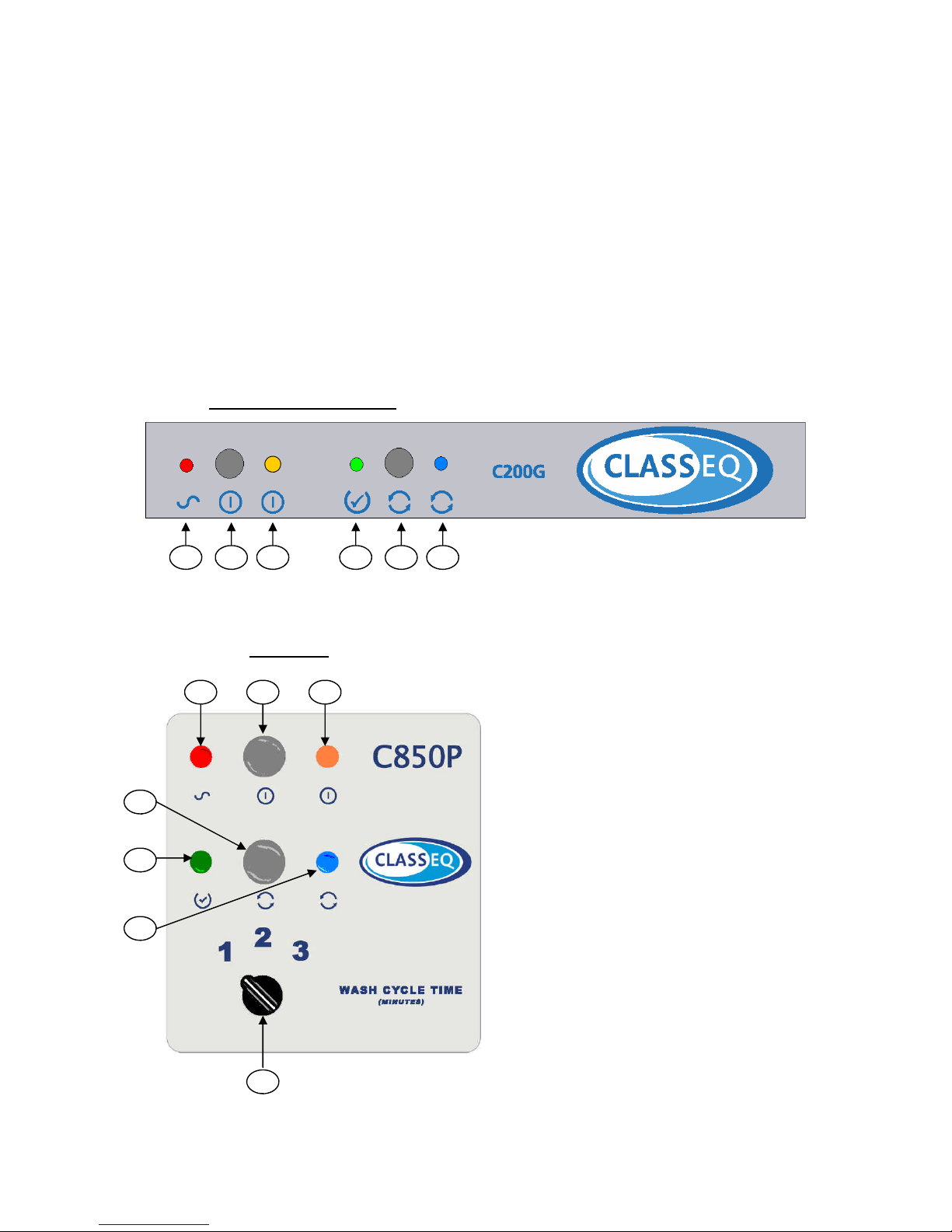
5.2 Controls :
Prior to switching the machine ON, ensure that you are familiar with the controls on the front fascia
of the appliance and the location of the isolator for mains electricity and water supply.
C200G, C500U, C300G, C750U
1. Power lamp (Red)
2. ON / OFF Button
3. ON / OFF Lamp (Yellow)
4. Machine Ready lamp (Green)
5. Wash Button
6. Cycle lamp
7. Selector switch (optional on C850P only)
In addition to these switches there are two further
switches on the front of the appliance
• Rinse Aid Prime button
• Refer to section 4.1.1 of this manual
• Continual wash button (optional)
• The function of this button will only work
when the machine is full and switch ON.
• Once depressed, the wash pump will run
for 10 minutes, during the cycle lamp 6 will
be illuminated.
• At the end of the 10 minutes neither the
rinse or drain pumps will operate
• This button must only be used when using
either lime scale remover or renovate
chemicals are being applied.
• Classeq recommends that once the cycle
has been completed that the machine is
switched OFF and allowed to fully drain
down
1 2 3 4 5 6
C850P (only)
2 1 3
4
5
6
7

Page 7
5.3 Switch the machine on :
Ensure that both the water and electrical supply are connected and turned on, then
depress the ‘ON/OFF’ button located on the front of the machine.
The machine will now automatically fill and heat, during this process the door should remain closed,
allowing the process to be completed quickly.
5.4 Machine ready to operate :
As state section 4.3 of this manual, it will be possible to start a cycle prior to the ‘Machine Green’
lamp being illuminated, to ensure NSF compliance ‘Classeq’ recommends that you wait for the
lamp to be illuminated before requesting a cycle to commence.
Please note for safety reason the wash heating element turns off when the door is opened,
’Classeq’ therefore advise that the door is closed between cycles.
5.5 Starting a cycle :
To start a cycle, open the door / hood, depending upon your appliance, load the first
basket, ensuring that all arms rotate freely.
Close the door, then depress the ‘Cycle’ button, your appliance will now automatically progress
though the cycle, during which time the ‘Cycle’ lamp will be illuminated.
At the end of the cycle open the door and remove the basket, then reload the machine
and repeat as required
5.6 Draining :
During normal operation your appliance will automatically drain away any excess water. ’Classeq’
recommends if your appliance is not being used for a prolonged period of time the machine must be
completely drained down
C200G and C500U
• Switch appliance OFF at the front
• Remove drain plug from wash tank.
• Ensure that door is closed
• Your appliance will now automatically drain down
• Once completed replace the drain plug.
• Now isolate main water and electricity at the wall.
C300G, C750U and C850P
• Switch appliance OFF at the front.
• Ensure the door is closed.
• Your appliance will now automatically drain down
• Once completed, isolate main water and electricity at the wall.
Note !
Once empty ‘Classeq’ recommends that the main water and electricity supplies are
isolated at the wall and the machine be cleaned as instructed in section 6 of this manual
For hygiene reasons it is recommended that once the appliance has been drained that
the door is left open to assist in natural drying of the wash chamber

Page 8
6.0 Cleaning
6.0 Cleaning
6.1 Prior to cleaning :
Switch off and isolate electrical supply before cleaning the appliance
WARNING
DO NOT use cleaning agents that contain CHLORINE, BLEACH or HYPOCHLORITE.
DO NOT use STEEL WOOL, WIRE BRUSHES or any other abrasive materials.
DO NOT jet wash or hose pipe the appliance down either internally or on the exterior
6.2 Internal cleaning :
Remove wash / rinse arms and filters from within the appliance, now remove
the individual wash and rinse jets from each arm and wash in warm soapy
water, ensuring all debris are removed then rinse in clean water before
reassembling and fitting back into the appliance.
WARNING
Before cleaning the wash chamber, ensure all sharp items, such as broken glass or
other items which could cause injury are removed carefully
Now wipe the inside of the wash chamber ensuring any debris are removed
and the chamber is clean, now reassemble all filters and wash arms.
6.3 Exterior cleaning :
Wipe the exterior of the appliance with a damp sponge (NOT WET)
Once dry, clean using a STAINLESS STEEL cleaning agent

Page 9
7.0 Trouble shooting
7.0 Trouble shooting
• Before placing a service call, please check the following:
• Check the appliance is connected to the main water and electricity supply and both are turned
on.
• Check levels of chemicals within the rinse aid and detergent bottles.
• Check the drain / stand pipe is correct for the appliance (refer to section 3.3.2 of this manual).
NOTE
In the event of a service call being made under Warranty, and it is found that the faults are due
to non-observance of instructions in this manual, the call will be charged at current rates.
7.1 Appliance does not fill :
Appliance does not start :
Appliance does not rinse :
• Check water supply is turned ON.
• Check water supply hose is not trapped or kinked.
• Check that the appliance is turned ON at the source.
• Drain appliance fully, then try again to fill the machine, drain as per instructions 5.6 of this
manual..
7.2 Appliance fills slowly :
• Check water supply valve is fully open.
• Check water supply pressure, should be above 30 lbs per square inch, if not ask your dealer
to install a booster pump to increase water pressure.
• Check and clean rinse jets (located on the wash arms within the appliance).
• Check water supply hose is not trapped or kinked.
• Remove any pressure regulator or reducer from the water supply.
7.3 Appliance not heating :
• Drain appliance fully, then try again to fill the machine, drain as per instructions 5.6 of this
manual.
• Check the temperature of the main water, as variations in water temperature will affect the
heating of the appliance.
• Check that the wash chamber is full of water.
7.4 Appliance not draining :
• Check and clean all filters within the appliance.
• Check that the stand pipe / drain is not clogged / blocked.

Page 10
7.5 Poor wash results :
• Check and replenish chemicals.
• Check and clean wash and rinse jets on wash arm assembly.
• Clean filters within appliance and check that they are fitted correctly.
• Check water supply is ON and fully open.
• Rinse dishes of any food debris before placing into the dishwasher.
• Glasses may need to be refurbished.
• If glasses are ‘Blooming’ you may need a water softener, call your dealer to advise on size of
water softener required.
• If connected to a water softener, replenish the salt within the softener, as per the water
softener instructions.
7.6 Overfilling :
• Drain appliance fully, then try again to fill the machine, drain as per instructions 5.6 of this
manual.
• Check and clean all filters within the appliance.
• Check that the stand pipe / drain is not clogged / blocked.
• If the appliance continues to overfill turn off both the main electricity and water, before call a
service technician.
7.7 Will not switch ON :
• Ensure there is main electrical supply
7.8 Will not switch OFF :
• Isolate at main electricity before calling for a service technician immediately.

E
D
C
B
F
A
E
D
C
B
F
A
87
65
4
3
2
1
87
65
4
3
2
1
of
Sheet
Approved
Drawn
Date
Name
Date
Comment
Revision
any other purpose without writtern permission from Classeq Ltd.
not be disclosed, loaned, copied or used for manufacturing, tendering or
DCN No.
Title
Loom / Dwg No.
This drawing and any information or descriptive matter set out hereon
are the confidential and copywright property of CLASSEQ LTD and must
© Classic Glass & Dishwashing Systems Ltd.
Special Notes
Standards
1
LM-C200G
D
C
B
Production
Production
Production
06/03/06
18/01/06
06/09/05
M.D.
M.D.
M.D.
04/08/05
M. Downing
T. Lovatt
DCN0051
DCN0053
1
UL and NSF
0
1
TCB-1
-SD3
Breaker
ZE-700-4
90
11
12
14
7.12.90
-APS5
Double APS Wash
A2-DP0401
17
21
22
24
11
12 14
-APS6
Rinse APS
Single (Oval)
18
11
12
A1
A2
14
31
32 34
21
22
24
CONT 30
-CT10
W Element Cont
46
11
12
A1
A2
14
31
32 34
21
22
24
-CT5
R element Cont
45
7.14.10/1
-Sw17
Door Sw
19
Q1
Q2
Q3
Q4
L1 NI1I2
I3 I4 I5 I6 I7
I8
LOGO!
230RCo
OUTPUT 4xRELAY/10A
INPUT 8xAC/DC
AC/DC 115..240V
RUN/STOP
Classic
Part No. :- ES-06
ES-06
-PLC2
Controller
51,52
11
12
A1
A2
14
31
32 34
21
22
24
CONT 30
-CT15
Cycle Latch
Cycle Lamp
49
7.12.6/9
-L9
Mc Ready Lamp
22
A2
A1 B1
1518 16
ES-07
-T5
RA timer
80.01
55
A2
A1 B1
1518 16
ES-07
-T6
Soap timer
80.01
55
Dishwash select
7.12.1/4
-SRS2
Wash trip
76
7.12.12/1
-IS1
Inlet sol. val.
67
Rinse Aid Soap
LN LN
8LPP4DS
-P5
Chemical Pump Assy
61,60
E (PE)
7.12.4/65
-Sw5
R. Aid Prime
1213C BLACK
110
LN
DP2
-P2
Drain Pump
DPS25-091
66
+
-
7.12.102
-C1
W. P. Capacitor
68
+
-
DS400-05-11
-C2
R. P. Capacitor
1274WC34400
68
7.12.1/4
-SRS13
Trip
79
L
N
9.12.17/2.5
-E2
Wash Element
82
7.12.6/8
-L6
Supply lamp
20
CR-31
Eyelet Crimp
34
CR-31
Eyelet Crimp
34
CR-31
Eyelet Crimp
34
500.0001
-Sw54
On/Off Switch
10
501.0001
-Sw55
Cycle sw
11
7.12.6/4
-L25
On/Off lamp
21
7.12.6/1A
-L26
Cycle lamp
23
540.0003
-MRS12
WE safety trip
71
540.0003
-MRS13
RE safety trip
70
L
N
7.12.17
-E13
Wash Element
82
CLC
N
E
DS400-05-10
-P6
Rinse Pump
UP60-159
63
1
23
456
C
NL
C
E
DS400-04-10
-P18
Wash Pump
CP50-163
64
11
12
A1
A2
14
31
32 34
21
22
24
CONT 30
-CT49
Door cont
40
Ground
Hot (1)
Hot (2)
Neutral
580.0001
-TB11
Terminal Block
1414400
30
Ground
Hot 1
Hot 2
501.0001
-Sw56
De Scale Sw
501.0001
-Sw57
R.Aid Prime
501.0001
Fascia EarthContactor Plate Earth
Cabinet Earth
C200G & C500U - Wiring Diagram (USA)
Disconnect if the m/c
is a glasswasher
39X
15 amp = Grey to terminal 31 of 'RE contactor'
28 amp = Brack to terminal 31 of 'RE contactor'
White
0.50 mm²
White
0.50 mm²
White
0.50 mm²
E
D
C
B
F
A
E
D
C
B
F
A
87
65
4
3
2
1
87
65
4
3
2
1
of
Sheet
Approved
Drawn
Date
Name
Date
Comment
Revision
any other purpose without writtern permission from Classeq Ltd.
not be disclosed, loaned, copied or used for manufacturing, tendering or
DCN No.
Title
Loom / Dwg No.
This drawing and any information or descriptive matter set out hereon
are the confidential and copywright property of CLASSEQ LTD and must
© Classeq Ltd.
Special Notes
Standards
1
LM-C750U
D
C
B
Trip added
Production
Production
06/03/06
18/01/06
06/09/05
M.D.
M.D.
M.S.
04/08/05
M. Downing
T. LovattDCN0051
DCN0053
1
UL and NSF
Ground
CR-31
Eyelet Crimp
34
CR-31
Eyelet Crimp
34
CR-31
Eyelet Crimp
34
0
1
TCB-1
-SD3
Breaker
ZE-700-4
90
L
N
HY306
-E1
Rinse Element
80
7.12.12/1
-IS1
Inlet sol. val.
67
LN
DP2
-P2
Drain Pump
DPS25-091
66
Rinse Aid Soap
LN LN
8LPP4DS
-P5
Chemical Pump Assy
61,60
E (PE)
L
N
9.12.17/2.5
-E2
Wash Element
82
7.12.4/65
-Sw5
R. Aid Prime
1213C BLACK
110
12
11
14
22
21
24
7.12.90
-APS5
Double APS Wash
A2-DP0401
17
1
23
456
C
NL
C
E
9.6.0/R
-P1
Wash Pump
H7
64
+
-
7.12.102
-C1
W. P. Capacitor
68
CLC
N
E
DS500-05-10
-P6
Rinse Pump
UP60-159
63
+
-
DS400-05-11
-C2
R. P. Capacitor
1274WC34400
68
7.14.10/1
-Sw17
Door Sw
19
11
12
A1
A2
14
31
32 34
21
22
24
-CT5
R element Cont
45
11
12
A1
A2
14
31
32 34
21
22
24
CONT 30
-CT10
W Element Cont
46
11
12
A1
A2
14
31
32 34
21
22
24
CONT 30
-CT15
Cycle Latch
49
7.12.6/8
-L6
Supply lamp
20
7.12.6/9
-L9
Mc Ready Lamp
22
11
12 14
-APS6
Rinse APS
Single (Oval)
18
7.12.1/4
-SRS2
Wash trip
76
7.12.1/4
-SRS13
Trip
79
Q1
Q2
Q3
Q4
L1 NI1I2
I3 I4 I5 I6 I7
I8
LOGO!
230RCo
OUTPUT 4xRELAY/10A
INPUT 8xAC/DC
AC/DC 115..240V
RUN/STOP
Classic
Part No. :- ES-06
ES-06
-PLC2
Controller
51,52
A2
A1 B1
1518 16
ES-07
-T5
RA timer
80.01
55
A2
A1 B1
1518 16
ES-07
-T6
Soap timer
80.01
55
Dishwash select
500.0001
-Sw54
On/Off Switch
10
501.0001
-Sw55
Cycle sw
11
7.12.6/4
-L25
On/Off lamp
21
7.12.6/1A
-L26
Cycle lamp
23
540.0003
-MRS12
WE safety trip
71
540.0003
-MRS13
RE safety trip
70
540.0003
-MRS14
RE safety trip
70
L
N
L
N
561.0001
-SS1
SSCF-25
63
11
12
A1
A2
14
31
32 34
21
22
24
CONT 30
-CT49
Door cont
40
L
N
TCB05
-TCB1
Breaker
-
91
Ground
Hot (1)
Hot (2)
Neutral
580.0001
-TB11
Terminal Block
1414400
30
Hot 1
Hot 2
501.0001
-Sw56
De Scale Sw
501.0001
-Sw57
R.Aid Prime
Fascia EarthContactor Plate Earth
Cabinet Earth
C300G & C750U - Wiring Diagram (USA)
Disconnect if the m/c
is a glasswasher
39X
White
0.50 mm²
White
0.50 mm²

E
D
C
B
F
A
E
D
C
B
F
A
87
6
5
4
3
2
1
87
6
5
4
3
2
1
of
Sheet
Approved
Drawn
Date
Name
Date
CommentRevision
any other purpose without writtern permission from Classeq Ltd.
not be disclosed, loaned, copied or used for manufacturing, tendering or
DCN No.
Title
Loom / Dwg No.
This drawing and any information or descriptive matter set out hereon
are the confidential and copywright property of CLASSEQ LTD and must
© Classeq Ltd.
Special Notes
Standards
1
LM-C850P
E
G
F
Trip Added
Trip posi
3 Phase
06/03/06
11/09/06
22/08/06
M.D.
M.D.
J.B.
04/08/05
M. Downing
T. Lovatt
DCN-0063
DCN0062
DCN0053
1
UL and NSF
0
1
TCB-1
-SD3
Breaker
ZE-700-4
90
11
12
14
7.12.90
-APS5
Wash APS
A2-DP0401
17
21
22
24
11
12 14
-APS6
Rinse APS
Single (Oval)
18
11
12
A1
A2
14
31
32 34
21
22
24
CONT 30
-CT10
W Element Cont
46
11
12
A1
A2
14
31
32 34
21
22
24
-CT5
R element Cont
45
7.14.10/1
-Sw17
Door Sw
19
Q1
Q2
Q3
Q4
L1
NI1I2 I3 I4 I5 I6 I7 I8
LOGO!
230RCo
OUTPUT 4xRELAY/10A
INPUT 8xAC/DC
AC/DC 115..240V
RUN/STOP
Classic
Part No. :- ES-06
ES-06
-PLC2
Controller
51,52
11
12
A1
A2
14
31
32 34
21
22
24
CONT 30
-CT15
Cycle Latch
Cycle Lamp
49
7.12.6/9
-L9
Mc Ready Lamp
22
A2
A1 B1
1518 16
ES-07
-T5
RA timer
80.01
55
A2
A1 B1
1518 16
ES-07
-T6
Soap timer
80.01
55
Dishwash select
L
N
HY306
-E1
Wash Element
80
7.12.1/4
-SRS2
Wash op trip
76
7.12.12/1
-IS1
Inlet sol. val.
67
Rinse Aid Soap
LN LN
8LPP4DS
-P5
Chem Pump Assy
61,60
E (PE)
7.12.4/65
-Sw5
R. Aid Prime
1213C BLACK
110
LN
DP2
-P2
Drain Pump
DPS25-091
66
+
-
7.12.102
-C1
W. P. Capacitor
68
CLC
N
E
DS500-05-10
-P6
Rinse Pump
UP60-159
63
+
-
DS400-05-11
-C2
R. P. Capacitor
1274WC34400
68
7.12.1/4
-SRS13
RE op trip
79
7.12.6/8
-L6
Supply lamp
20
CR-31
Eyelet Crimp
34
CR-31
Eyelet Crimp
34
CR-31
Eyelet Crimp
34
500.0001
-Sw54
On/Off Switch
10
501.0001
-Sw55
Cycle sw
11
7.12.6/4
-L25
On/Off lamp
21
7.12.6/1A
-L26
Cycle lamp
23
1
23
456
C
NL
C
E
9.6.0/R
-P1
Wash Pump
H7
64
540.0003
-MRS13
RE safety trip
70
L
N
9.9.14
-E13
Rinse Element
82
L
N
9.9.14
-E14
Rinse Element
82
540.0003
-MRS15
WE safety trip
71
11
12
A1
A2
14
31
32 34
21
22
24
CONT 30
-CT49
Door Cont
40
L
N
TCB05
-TCB1
1.8A breaker
Hot 1
Hot 2
Ground
L
N
TCB05
-TCB3
8A breaker
11
12
A1
A2
14
31
32 34
21
22
24
CONT 30
-CT50
40
11
12
A1
A2
14
31
32 34
21
22
24
CONT 30
-CT51
40
501.0001
-Sw56
De Scale Sw
501.0001
-Sw57
R.Aid Prime
Ground
Hot (1)
Hot (2)
Neutral
580.0001
-TB11
Terminal Block
1414400
30
IIIIII
IIIIII
502.0001
-Sw58
Selector Sw
3SB400-0C
12
11
12
A1
A2
14
31
32 34
21
22
24
CONT 30
-CT53
40
Fascia Earth
Contactor Plate Earth
Cabinet Earth
C850P - Wiring Diagram (USA)
Disconnect if the m/c
is a glasswasher
39X
White0.50 mm²
White0.50 mm²
White
0.50 mm²

Classeq Inc.
1006 Corporate Lane
Export
PA15632
Tel: 724 733 2391
Fax: 724 733 2491
Notes
 Loading...