

Page 1

Issue 1
www.class-connection.com
VC-24
TALKBACK INTERCOM SYSTEM
EXPANDABLE 24/48/72/96 ZONE
CONTENTS
INTRODUCTION 1, 2
SPECIFICATIONS 2, 3
INSTALLATION 3, 4
Precautionary Information 3, 4
VC-24 Control/Connector Locations 5
Punchdown Block Connections 6
Attendant Port Connection 7
Background M usi c Connection 7
Door Speaker/Call Switch Connection 7
Inhibit Option 8
External Tone Source (ex.V-9927A) 8
SMDR Printer Port Cable 8
Override Page Port 9
Global All Call Page 9
Global Priority Page 9
Zone Page Option 10
Clock Sync 10
Dipswitch Options 11
Programming Tool 11-26
OPERATION 27,28 VC-24 with VC-24EXP Expansion Unit
Remote Station Access (Call Button) 28
Attendant Station Dialing Plan 28
TROUBLESHOOTING CHART 29
LIMITED WARRANTY 29
GLOSSARY OF TERMS 30
The VC-24 Talkback Intercom System provides 24 stations with one-way, two-way, group call and all call pages.
Each station can be programmed for one-way or two-way communication. The stations may be grouped into oneway page groups. The system also provides the ability for a remote speaker location equipped with a call button to
call the attendant location. The attendant receives calling speaker identification when using a Caller ID equipped
telephone or a Caller ID display.
The VC-24 is compatible with standard 45 ohm speakers and one-way amplified speakers and can be accessed via a
single line phone, E-Key line port or PABX loop start trunk port. An RS-232 port on the control unit provides a
connection for a serial printer for printout of system activity.
The VC-24 provides a background music input and is designed to automatically mute music during a page. The
basic system also provides four (4) contact closures associated with the last 4 zones to allow for door strike plate
activation. Multiple VC-24 control units can be interconnected to allow global all call and global priority pages for
up to six (6) VC-24 control units.
1 947226
Page 2

The VC-24 Control Unit provides access to 24 stations. A VC-24EXP Expansion Unit is available for the VC-24.
Each VC-24EXP Expansion Unit will increase the capacity of the VC-24 by twenty-four (24) additional stations. Up
to three (3) Expansion Units can be added to a system for a total of 48, 72, or 96 zones of paging.
“WARNING: To reduce the risk of fire or electric shock, do not expose this appliance to rain or
moisture.”
“WARNING: Shock hazard – Do Not Open.”
“AVIS: Risque de choc Electrique ne pas Ouvrir.”
“PELIGRO: Corriente Electrica – No Abres.”
FEATURES
• 24 zones of handsfree or one-way
communication (expandable up to 96 zones)
• Built-in handsfree amplifier
• Background music input
• Built-in all call with “meet me” and “follow me”
capability
• “Ring in” from speaker locations
• Calls placed in queue
• Dial tone programmable (On/Off)
• Alert tone
• Ringback tone
• Repeated alert/privacy tone programmable
(On/Off)
• Auxiliary contact closures for zones 21, 22, 23,
24
• Programmable ring pattern
• Ring contact closure follows ring cycle
• Inhibit input
• Caller identification
• RS-232 serial printer port
• Control unit is internally powered (battery
backup compatible; (1) VPB-260 per unit)
• Override port
• Emergency tone input
• Time tone input
• UNA contact closure input
• All call/priority page through up to six VC-24
systems of any size
• Group call
• Programmable class of service
• Time sync output
• Custom page groups
• Enhanced Caller ID
• Flexible Architectural numbering plan
• Interface to the PC Programming Tool
• Store user data to EEROM
• Real time clock for SMDR printer
• Auto detect for Com Port or Modem
• Auto adjust for Daylight Savings Time
• Evacuation tone to specified groups
• Time tones to specified groups
• Read software/firmware revision numbers
CAPACITY
• The VC-24 is a single talkpath unit.
• The maximum number of speakers per zone:
one 45 ohm speaker and/or forty (40) one-way
amplified speakers.
NOMINAL SPECIFICATIONS
These units are not intended for direct or indirect
connection to the public telephone network. When
used with a customer premise telephone system such
as a key system or PABX system, these units are
interfaced to the system via a fully protective paging
port or a system central port, which are fully
protected interface devices. Additionally, the host
system must be configured to disallow a central
exchange trunk co nferencing in ord er to prevent
indirect connection to the network.
Attendant Port
• Loop Start Access (E-Key C. O. Line Position,
Single Line Phone, Trunk Port of PABX)
• DTMF Access
• Caller ID Compatible
• Tip and Ring Input Impedance: 600 Ω
• Tip and Ring Input Level: -10 dBm nominal
Ring Supply
90 Vac, 30 Hz - Ring Patterns:
2 sec ON, 4 sec OFF American
1 sec ON, 4 sec OFF Dutch
Double Ring British
Override Page Port
• Loop Start Access (E-Key C. O. Line Position,
Single Line Phone, Trunk Port of PABX)
• Telephone System Page Port Access
2 947226
Page 3
• Tip and Ring Input Impedance: 600 Ω
• Tip and Ring Input Level: -10 dBM nominal
Background Music Amplifiers
Input Impedance: 10 K Ω
Frequency Response: 50 Hz to 17 kHz +/- 3 dB
Distortion: < 1.0 %
Signal to Noise: -70 dB
Output Impedance: 45 Ω
Output Power: 1 watt per zone
Page Amplifiers
Frequency Response: 150 Hz to 7.5 kHz +/- 3 dB
Distortion: < 1.0 %
Signal to Noise: -70 dB
Output Impedance: 45 Ω
Output Power: 1 watt per zone
POWER REQUIREMENTS
Operating Voltage: 115, 230 Vac
Current: 1.0 Amp @ 115 Vac
0.5 Amp @ 230 Vac
Frequency: 50, 60 Hz
ADDITIONAL INPU TS
Inhibit (Ground Activated)
Emergency Tone Input
Input impedance: 10 K Ω
Input Level: -10 dBm
Time Tone Input
Input impedance: 10 K Ω
Input Level: -10 dBm
PRINTER PORT
Type: Serial
Baud Rate: 9600
8 Data Bits, No Parity, 1 Stop Bit
• Background music system-wide level control
• All call level
• Priority page level
AUXILIARY CONTACTS
• Contact Closures are available on Zones 21, 22,
23, and 24 (strike plates) (Main Unit). Each
contact operates when the respective zone
number is dialed and the “*” key is pressed
twice.
• Remote Signaling Closure (follows ring patter n)
250 mA max @ 24 Vdc.
PAGE PRIORITY
It is possible for multiple inputs to request an audio
connection to a speaker at the same time. When a
conflict occurs, the highest priority audio will be
connected. A lower priority input that is overridden
will be re-connected if it is still active in the system
when all higher priority inputs have ended. Priorities
from highest to lowest:
Override Phone
Emergency Tone (continued…)
Time Tone
Inhibit
Handsfree Call
External All Call Page
All Call Page
Group Call Page
Night Ring
Background Music
INSTALLATION
Precautionary Information
CAUTION
RISK OF ELECTRIC SHOCK
DO NOT OPEN
ENVIRONMENT
Temperature: 0 to 40 °C
Humidity: 0-85% Non-precipitating
CAUTION: To reduce the risk of electric shock,
Do not remove cover.
No user serviceable parts inside.
Refer servicing to qualified service personnel.
DIMENSIONS/WEIGHT
• 17.50”H x 10.31”W x 3.06”D
(44.45cm H x 26.19cm W x 7.77cm D)
• 15 lbs. (6.8 kg)
This symbol indicates that dangerous
voltage constituting a risk of electric
shock is pre s ent within this unit.
MAIN UNIT CONTROLS
• Tone level for internally generated tones (one
control hand l es time, emergency and UNA tone s)
This symbol indicates that there are
important operating and maintenance
instructions in the literature accomp anying
this unit.
• Tone level for externally generated tones (one
control hand l es time and emergency tones)
• Phone to speaker level
• Speaker to phone level
FCC Notice
This equipment has been tested and found to comply
with the limits for Class A digital devices, pursuant to
Part 15 of FCC Rules. These limits are designed to
3 947226
Page 4

provide reasonable protection against harmful
interference when the equipment is operated in a
commercial environment. This equipment generates,
uses, and can radiate radio frequency
energy and, if not installed and used in accordance
with the instruction manual, may cause harmful
interference to radio communications. Operation of
this equipment in a residential area is likely to cause
harmful interference in which case the user will be
required to correct the interference at his own
expense.
Mounting
The VC-24 was designed for wall mounting only.
Using the enclosed paper template, mark the locations
for the mounting screws on a plywood backboard
(minimum ½” thick). Insert screws and tighten to
within 1/8” of the surface. Hang the unit on the
screws, slide the unit left to the narrow end of the
slots and tighten screws firmly.
Connections
Mount (3) 66B type punchdown blocks on the
backboard near the VC-24 control unit. Make
connections to the punchdown blocks as specified in
Figure 2 - Punchd own Block Connections. (System
Inputs - Block P7, Speaker Outputs - Block P3,
Switch Inputs - Block P6). Also refer to the
following diagrams for connections of each
application.
Setting Option Switches
After all connections have been made, set the option
switches to fit the specific user requirements. Refer
to Figure 1 for location and Table 1 for the default
values of the vario us switche s. Make changes as
required.
NOTE:
This unit provides an option for
disabling Talkback Alert Tone and Repeating
Privacy Tones. Check local privacy
regulations prior to disabling these tones.
Power Connections
Use a cord set consisting of a minimum 18 AWG
cord and grounding type attachment plug rated a
minimum of 15A, 250V. The cord set should have
the appropriate safety approvals for the country in
which the equipment will be installed and marked
HAR.
The VC-24 may be provided with one of the
following:
• NEMA 5-15 cordset for North American use
• CEE/7 cordset for Continental European use
• BS1363 cordset for United Kingdom use
Connect cordset to unit via IEC 320 female connector located on one
end of cordset to IEC 320 male appliance coupler located on VC-24.
• For 115 VAC use
selector switch displays 115 V.
• For 230 VAC use
selector switch display 230 V.
• After all required connections have been made, plug the cordset
into appropri ate AC wall outlet.
, verify fuse rating of 1 amp and voltage
, verify fuse rating of .5 amp and voltage
For United Kingdom use:
As the colors of the cores in the main lead may not
correspond with the colored markings identifying the
terminals in your plug, proceed as follows:
• The core which is colored green and yellow must
be connected to the terminal in the plug which is
marked with the letter E or by the earth symbol
(inverted Christmas tree), or colored green and
yellow.
• The core which is colored blue must be
connected to the terminal which is marked with
the letter N or colored black.
• The core which is colored brown must be
connected to the terminal which is marked with
the letter L or colored red.
4 947226
Page 5
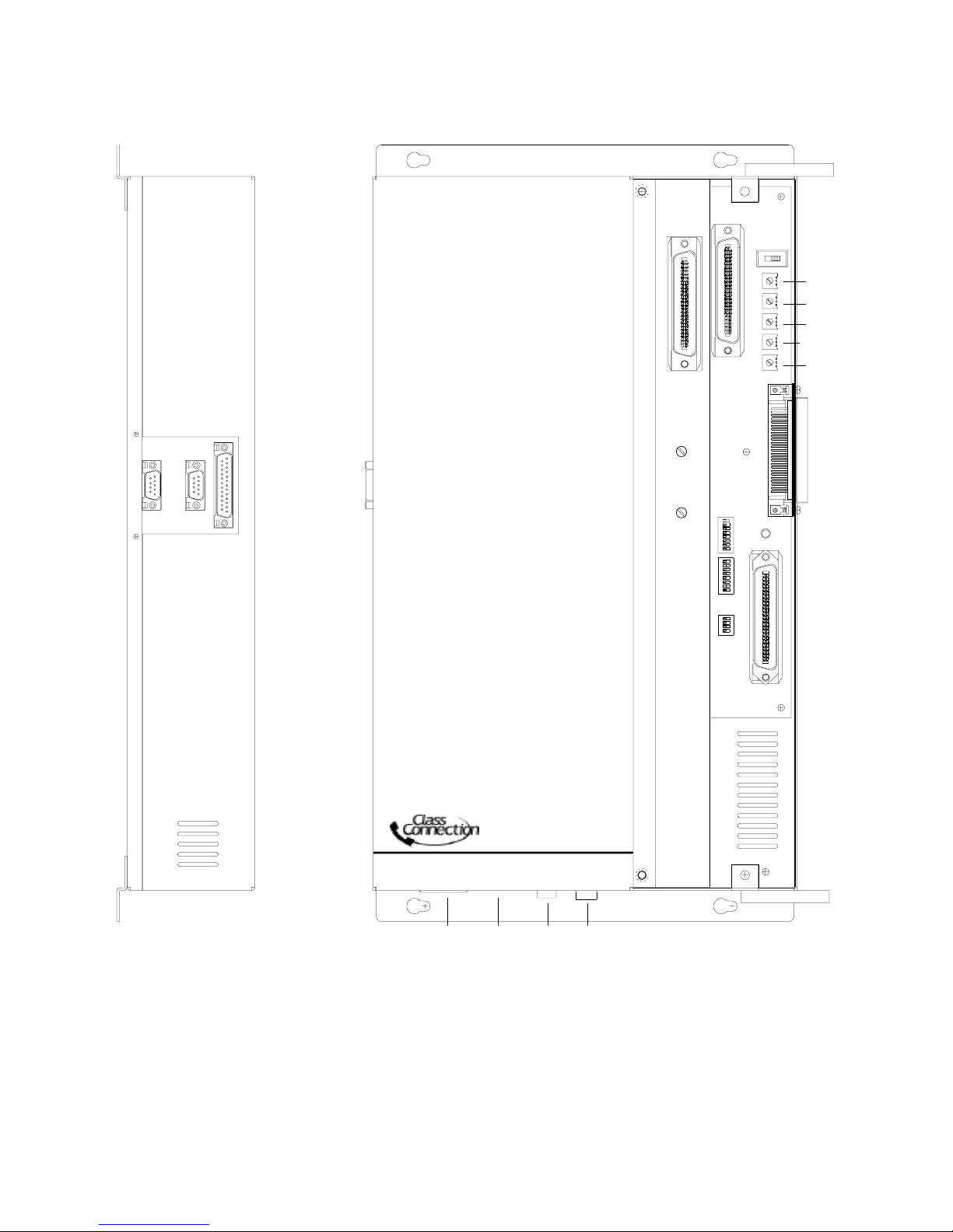
FIGURE 1 - VC-24 CONTROL AND CONNECTOR LOCATIONS
Side View
P10
P10
Top View
P3
R16
R11
P7
SW4
R79
R80
R82
R115
R81
P8
SW2
SW3
Switches:
SW1
SW2, SW3
SW4
Connectors:
P3
P6
P7
P8
P10
VC-24
AC
Power
- NOT USED
- NOT USED
- Battery Feed Switch (Priority Port)
- 45 ohm Speakers (See Figure 2)
- Call-In Switch Inputs (See Figure 2)
- System Connections (See Figure 2)
- Expansion Unit Connector
- RS232 Serial Port for SMDR (DB9 Connector)
Switch
Volume Controls:
R11
R16
R79
R80
R81
R82
R115
Fuse115/230
Battery Backup
Connector
- Handsfree Speak er to Pho ne Level
- Handsfree Phone to Speaker Level
- Backg round Music Lev el
- External Tone Source Level
- All Call Adjust Volume/Attendant Level
- Override Port Page Level
- Internal Tone Source Level
SW1
P6
5 947226
Page 6
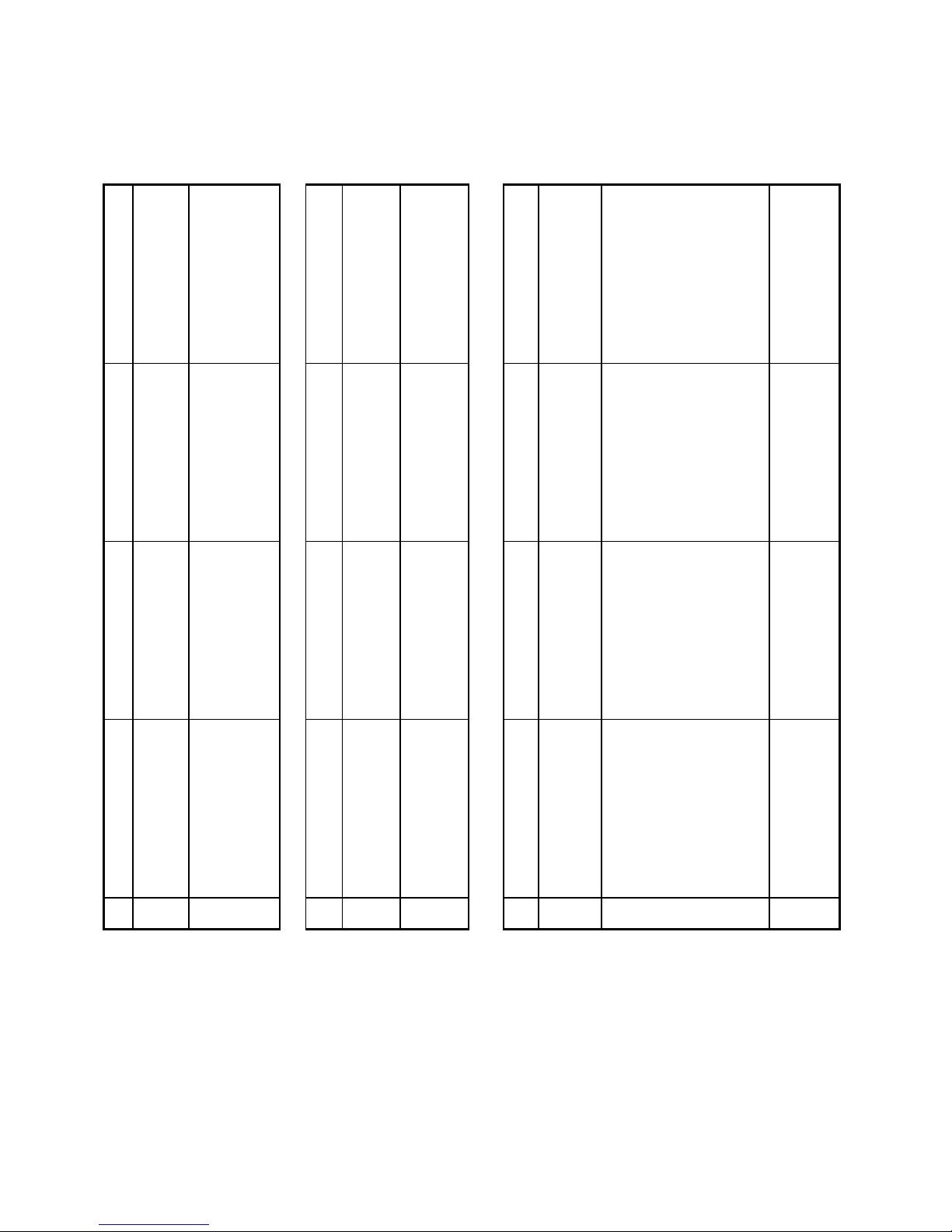
FIGURE 2 - PUNCHDOWN BLOCK CONNECTIONS
Block P3 - Speaker Outputs Block P 6 - Switch Inputs Block P7 - System Inputs
Group 1
Group 2
Group 3
Group 4
27
28
29
30
31
33
34
35
10
36
11
37
12
13
39
14
40
15
41
16
42
17
43
18
19
45
20
46
21
47
22
48
23
49
24
25
1
2
3
4
5
6
7
8
9
W/BL
BL/W
W/O
O/W
W/GR
GR/W
W/BR
BR/W
W/S
S/W
R/BL
BL/R
R/O
O/R
R/G
G/R
R/BR
BR/R
R/S
S/R
BK/BL
BL/BK
BK/O
O/BK
BK/G
G/BK
BK/BR
BR/BK
BK/S
S/BK
Y/BL
BL/Y
Y/O
O/Y
Y/G
G/Y
Y/BR
BR/Y
Y/S
S/Y
V/BL
BL/V
V/O
O/V
V/G
G/V
V/BR
BR/V
V/S
S/V
INA1
INB1
INA2
INB2
INA3
INB3
INA4
INB4
INA5
INB5
INA6
INB6
INA7
INB7
INA8
INB8
INA9
INB9
INA10
INB10
INA11
INB11
INA12
INB12
INA13
INB13
INA14
INB14
INA15
INB15
INA16
INB16
INA17
INB17
INA18
INB18
INA19
INB19
INA20
INB20
INA21
INB21
INA22
INB22
INA23
INB23
INA24
INB24
N. C.
N. C.
27
28
29
30
31
33
34
35
10
36
11
37
12
13
39
14
40
15
41
16
42
17
43
18
19
45
20
46
21
47
22
48
23
49
24
25
1
2
3
4
5
6
7
8
9
W/BL
BL/W
W/O
O/W
W/GR
GR/W
W/BR
BR/W
W/S
S/W
R/BL
BL/R
R/O
O/R
R/G
G/R
R/BR
BR/R
R/S
S/R
BK/BL
BL/BK
BK/O
O/BK
BK/G
G/BK
BK/BR
BR/BK
BK/S
S/BK
Y/BL
BL/Y
Y/O
O/Y
Y/G
G/Y
Y/BR
BR/Y
Y/S
S/Y
V/BL
BL/V
V/O
O/V
V/G
G/V
V/BR
BR/V
V/S
S/V
W/BL
26
BL/W
1
W/O
27
O/W
2
W/GR
28
GR/W
3
W/BR
29
BR/W
4
W/S
30
S/W
5
R/BL
31
BL/R
6
32
R/O
7
O/R
33
R/G
8
G/R
34
R/BR
9
BR/R
35
R/S
10
S/R
36
BK/BL
11
BL/BK
37
BK/O
12
O/BK
38
BK/G
13
G/BK
39
BK/BR
14
BR/BK
40
BK/S
15
S/BK
41
Y/BL
16
BL/Y
42
Y/O
17
O/Y
43
Y/G
18
G/Y
44
Y/BR
19
BR/Y
45
Y/S
20
S/Y
46
V/BL
21
BL/V
47
V/O
22
O/V
48
V/G
23
G/V
49
V/BR
24
BR/V
50
V/S
25
S/V
T STA 1
R STA 1
T STA 2
R STA 2
T STA 3
R STA 3
T STA 4
R STA 4
T STA 5
R STA 5
T STA 6
R STA 6
T STA 7
R STA 7
T STA 8
R STA 8
T STA 9
R STA 9
T STA 10
R STA 10
T STA 11
R STA 11
T STA 12
R STA 12
T STA 13
R STA 13
T STA 14
R STA 14
T STA 15
R STA 15
T STA 16
R STA 16
T STA 17
R STA 17
T STA 18
R STA 18
T STA 19
R STA 19
T STA 20
R STA 20
T STA 21
R STA 21
T STA 22
R STA 22
T STA 23
R STA 23
T STA 24
R STA 24
N. C.
N. C.
26
32
38
44
50
26
32
38
44
50
Tip - Attendant Tel
Ring - Attendant Tel
Common Audible C.C.
Common Audible C.C.
BGM Input
BGM Input
Riot Mode
Riot Mode
External Tone - Tip
External Tone - Ring
Clock Activat e
Clock Activat e
Clock Enable C. C.
Clock Enable C. C.
Emergency Activat e
Emergency Activat e
Emergency Enable C. C.
Emergency Enable C. C.
Override Page Port - Tip
Override Page Port - Ring
Dry Priority Activate
Dry Priority Activate
Inhibit
Inhibit
Schedule Contact Closure 1
Schedule Contact Closure 1
Schedule Contact Closure 2
Schedule Contact Closure 2
Schedule Contact Closure 3
Schedule Contact Closure 3
Schedule Contact Closure 4
Schedule Contact Closure 4
Global Priority Activate
Global Priority Activate
Global All Call Activat e
Global All Call Activat e
Global Page Tip
Global Page Ring
Clock Sync
Clock Sync
Night Ring Activate
Night Ring Activate
Sta. 21 C. C.
Sta. 21 C. C.
Sta. 22 C. C.
Sta. 22 C. C.
Sta. 23 C. C.
Sta. 23 C. C.
Sta. 24 C. C.
Sta. 24 C. C.
6 947226
Page 7
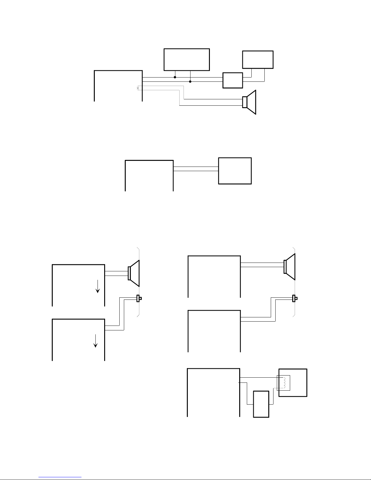
ATTENDANT PORT CONNECTION
P7 Connecting Block
26
W/BL
1
BL/W
27
W/O
2
O/W
Tel. System
C. O. Line Port
T R
OR
Caller
ID Box
External
Signalling
Device
Telephone
T R
BACKGROUND MUSIC CONNECTION
P7 Connecting Block
W/GR
GR/W
28
3
Low Level
Music
Source
DOOR SPEAKER AND CALL SWITCH CONNECTION
(STATION S 1-20)
Block P3 Speaker Outputs
26
45
20
26
45
20
1
1
TSTA 1
RSTA 1
TSTA 20
RSTA 20
Block P6 Switch Inputs
INA 1
INB 1
INA 20
INB 20
Door Plate
Speaker
Pushbutton
(STATIONS 21-24)
Block P3 Speaker Outputs
TSTA 21
RSTA 21
TSTA 22
RSTA 22
TSTA 23
RSTA 23
TSTA 24
RSTA 24
Block P6 Switch Inputs
INA 21
INB 21
INA 22
INB 22
INA 23
INB 23
INA 24
INB 24
Block P7 System Inputs
Sta.21 CC
Sta.22 CC
Sta.23 CC
Sta.24 CC
47
22
48
23
49
24
50
25
46
21
47
22
48
23
49
24
46
21
47
22
48
23
49
24
Gnd
Door Plate
Speaker
Pushbutton
Customer provided
door opening solenoid
-24 Vdc
7 947226
Power Supply
for door solenoid
Page 8
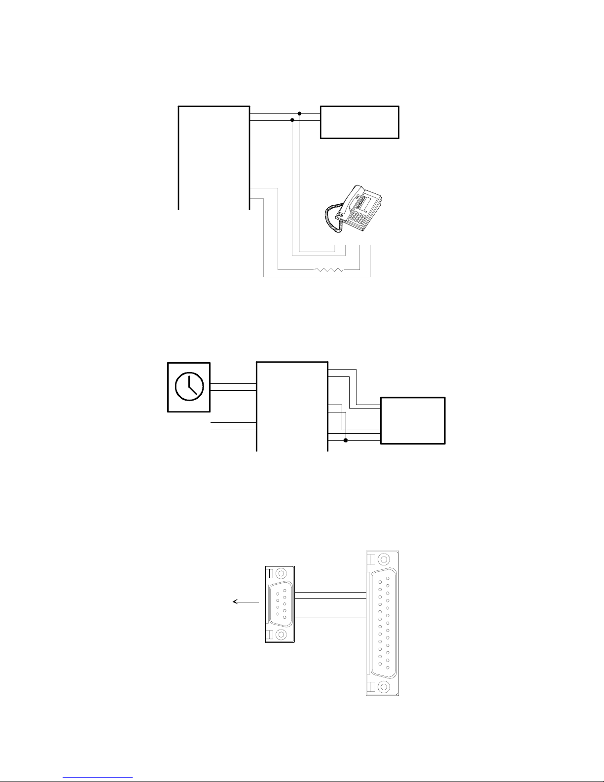
INHIBIT OPTION
P7 Connecting Block
26
W/BL T
1
BL/W R
37
BK/O
12
O/BK
Inh.
Inh.
Tel.Sys. C.O. Line
positio n or sin gle
line telephone
Dedicated "Meet
Me" Telephone
T R A A1
5.1K Ohm
EXTERNAL TONE SOURCE USING A V-9927A
P7 Connecting Block
30
31
33
W/S
S/W
6
R/O
O/R
8
R/BR
BR/R
32
34
5
7
9
V-9927A
Signal
Out
(1-8)
Com
Emergency
Closure
Normally
Open Switch
Control
from time
clock
*NOTE: External tone source requires programming option to enable
feature. See Table 1(SW3-8)
SMDR PRINTER PORT CABLE
DB25 Male
DB9 Female
To P10
VC-24
Control
Unit
Baud Rate 9600, 8 bit, no parity, 1 stop bit
8 947226
22
33
57
Page 9
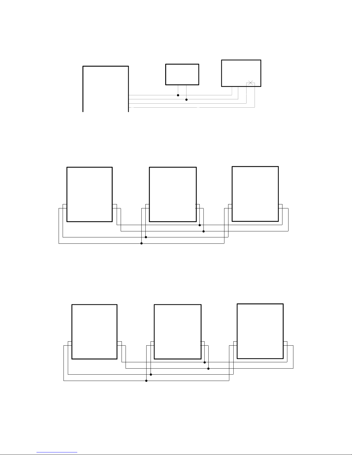
OVERRIDE PAGE PORT
P7 Connecting Block
35
R/S
10
S/R
36
BK/BL
11
BL/BK
Telephone
(SW4 ON)
TR
OR
SW4 on the control board
must be set accordingly
Tel System
Page Port
(SW4 OFF)
GLOBAL ALL CALL PAGE (FROM ATTENDANT DIAL UP)
VC-24 #1 VC-24 #2
P7 Connecting Block
Y/G
G/Y
Y/BR
BR/Y
44
19
43
18
NOTE: Global all call page requires programmi ng option to enable feature.
P7 Connecting Block
43
18
Y/G
G/Y
Y/BR
BR/Y
44
19
VC-24 #3
P7 Connecting Block
Y/G
43
G/Y
18
GLOBAL PRIORITY PAGE (FROM OVERRIDE PAGE PORT)
VC-24 #1 VC-24 #2
P7 Connecting Block
P7 Connecting Block
VC-24 #3
P7 Connecting Block
Y/BR
BR/Y
44
19
42
17
Y/O
O/Y
44
Y/BR
19
BR/Y
NOTE: Global all call page requires programmi ng option to enable feature.
9 947226
42
17
Y/O
O/Y
Y/BR
BR/Y
44
19
42
17
Y/O
O/Y
Y/BR
BR/Y
44
19
Page 10
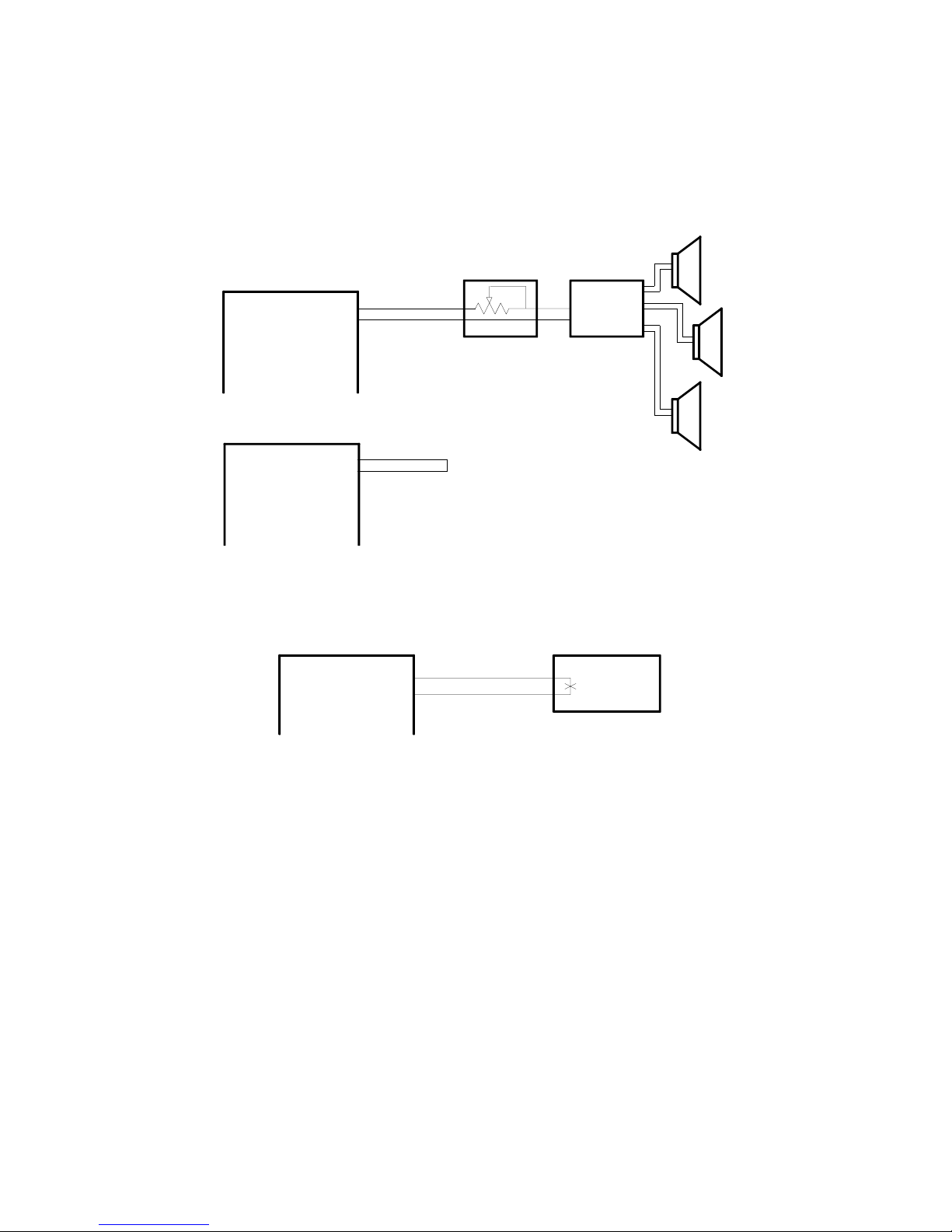
ZONE PAGE OPTION
ONE WAY ONLY
P3 Speaker Outputs
TSTA1
RSTA1
TSTA2
RSTA2
TSTA3
RSTA3
P6 Switch Inputs
INA1
INB1
INA2
INB2
INA3
INB3
P7 Connecting Block
26
1
27
2
28
3
26
1
27
2
28
3
* To Enable Feature, strap must remain
across pair when unit is powered
CLOCK SYNC INPUT
Y/S
S/Y
45
20
V-1092
70 Volt
Amp
Master
Clock
Master Clock must make contact closure at 0200 Hours.
10 947226
Page 11

Dipswitch Options - Basic System
Note SW1, SW2 and SW 3 are not used in the VC-24 System.
Override Port Options
Switch OFF Switch ON
Main Board SW4
Tel. System Page Port A ccess
Loop Start Trunk Port
INSTALLATION OF THE PROGRAMMING TOOL
The VC-24 Programming Tool is a windows based software tool designed to interface with the VC-24.
Minimum Computer Requirements for the Class Connection
TM
VC-24 Programming Tool:
Hardware:
• 80486 (higher is recommended)
• Hard drive with 30 Mbytes free
• Mouse
• 8 Mbytes of RAM (more is recommended)
• 1 available serial communication port
Operating System:
• The Programming Tool is 32-bit and requires Windows 95, Windows 98, or Windows NT 4.0.
The programming tool software is furnished on 1.4 MB disks and must be installed to the hard drive. To install the
software:
• On the taskbar, click the Start button
• Insert disk 1
• Select Run
• Type a:\Setup (Assuming a: is the disk dr ive being used)
• Follow on-screen instructions for full installation, changing disks as the prompt requests
• The Class Connection
TM
VC-24 Programming Tool will automatically appear in the Programs list
USING THE PROGRAMMING TOOL
• On the taskbar, click the Start button, point to Programs, and select Class ConnectionTM VC-24
Programming Tool.
• The VC-24 Programming Tool splash screen appears momentarily and then the Programming screen
comes into view
11 947226
Page 12
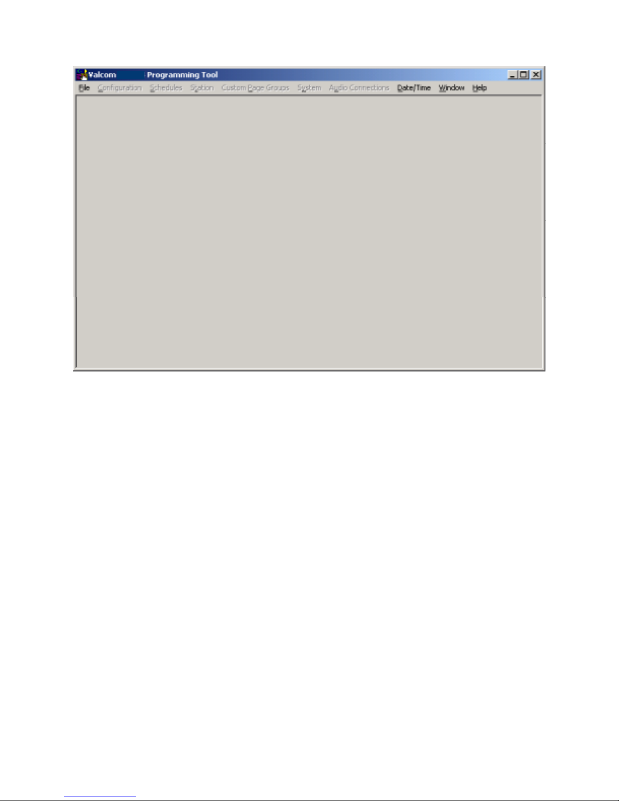
VC-24
System Configuration
To begin the programming process, click on File. A pull-down menu appears allowing selection of a previously
programmed file (click on Open) or the ability to create a new file (click on New). The following instructions
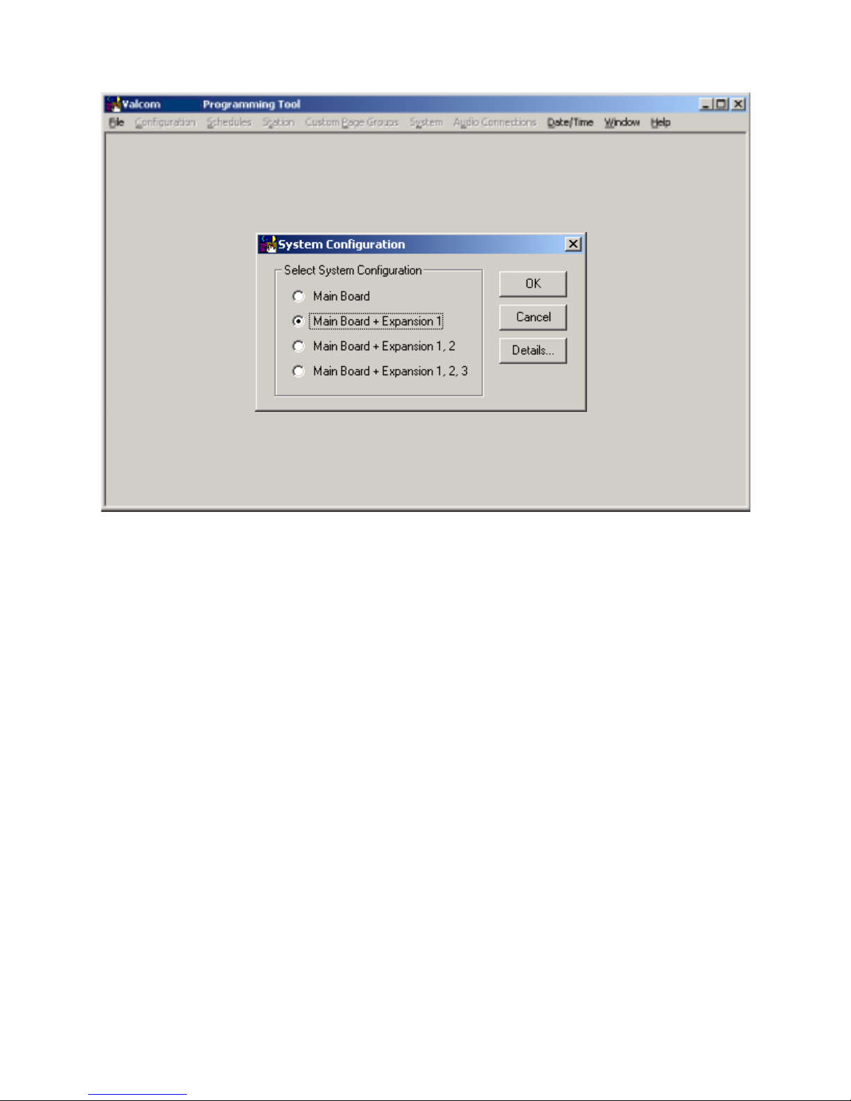
assume a New configuration file is being created. Click on New from the pull-down menu. A System Configuration
screen is displayed to allow selection of the installed components within the system.
Select one of the following from the list:
• For a 24-station system select Main Board.
• For a 48 station system select Main Board + Expansion 1.
• For a 72 station system select Main Board + Expansion 1, 2.
• For a 96 station system select Main Board + Expansion 1, 2, 3.
Press OK to accept the present selection or Cancel to re-select. When selection is complete, the
Programming Window Screen will be displayed. (To display the configuration of the system
press the Details button).
12 947226
Page 13
VC-24
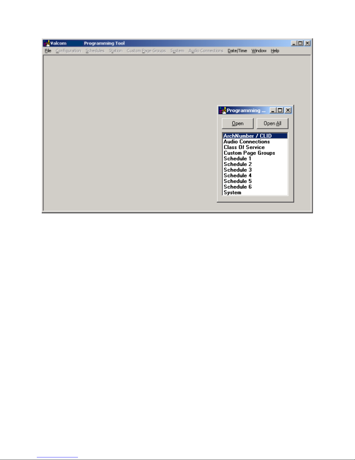
When OK is selected from the System Configuration screen, the Programming Window appears
- see below. The Programming Window allows each option to be accessed by selecting the
option and pressing Open or by double clicking on the selected option. All functions can be
listed at once by pressing Open All. (All of the options accessed through the Programming
Window can also be accessed from the pulldown menus).
13 947226
Page 14
VC-24
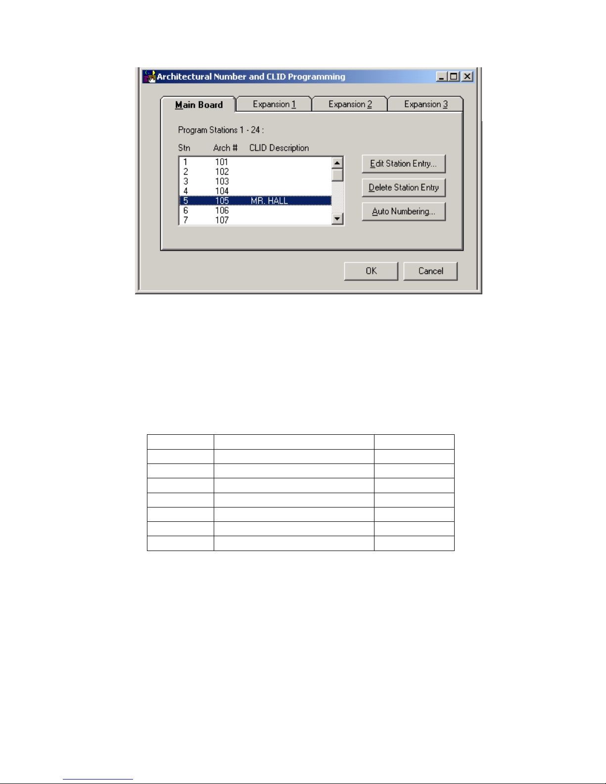
Architectural Number and CLID (Caller ID) Programming
The first function to configure is the Architectural Number and CLID Programming.
The Architectural Number is a 1 to 4 digit number that is dialed by the phone to connect to a
specific speaker. Flexible architectural numbering is often selected to allow speakers and room
numbers to match. The CLID Programming allows a name or up to 15 characters description to
be entered for each station.
The information entered in the CLID description field will be displayed on the phone or Caller
ID unit if provided as part of the system.
The Edit Station Entry allows a CLID description to be entered for each station. Example:
105 would be the Arch # and MR. HALL would be the CLID description (15 character limit).
The Delete Station Entry allows removal of selected architectural and CLID descriptions.
Auto Numbering assigns the Arch # in sequential order. The beginning number is the currently
selected station; an ending number must be specified.
To Auto Number – Highlight station where architectural numbering begins.
Select Edit Station Entry. Enter beginning architectural number and select OK.
Select Auto Numbering and enter last architectural number (must be a higher number).
Select OK.
14 947226
Page 15
Enter information for the Main Board as well as each Expansion Unit being used and press OK
to accept.
Audio Connections
This screen allows selection of groups to receive Background Music, Time Tones and
Emergency Tones. This sample system consists of a “Main Board + Expansion 1” so eight
groups are available to receive audio connections. (Each group contains six stations).
Group 1 Stations 1, 2, 3, 4, 5, 6 Main Board
Group 2 Stations 7, 8, 9, 10, 11, 12 Main Board
Group 3 Stations 13, 14, 15, 16, 17, 18 Main Board
Group 4 Stations 19, 20, 21, 22, 23, 24 Main Board
Group 5 Stations 25, 26, 27, 28, 29, 30 Expansion 1
Group 6 Stations 31, 32, 33, 34, 35, 36 Expansion 1
Group 7 Stations 37, 38, 39, 40, 41, 42 Expansion 1
Group 8 Stations 43, 44, 45, 46, 47, 48 Expansion 1
Click on the tab of the desired feature to program zones. Click on each group button to receive
the audio connection. If all groups are to receive an audio connection for the specific feature,
select Include All.
15 947226
Page 16
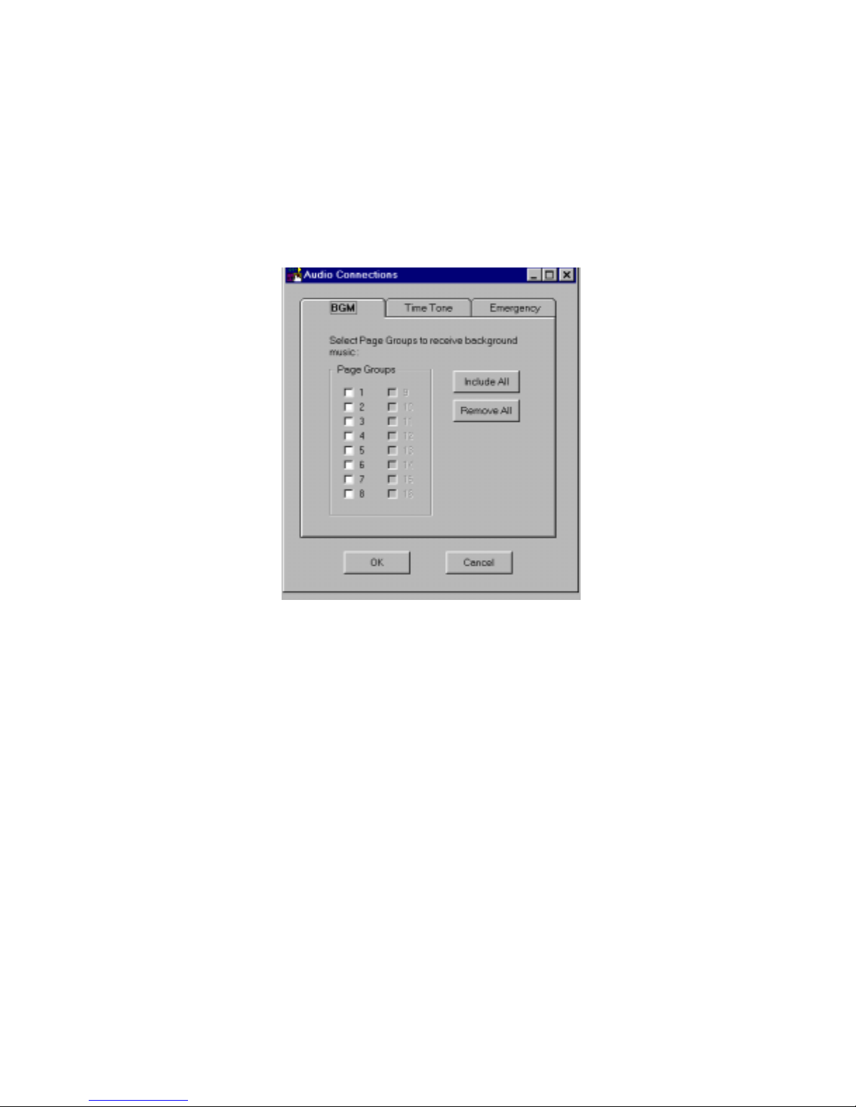
The zones for each feature:
BGM, Time Tone and Emergency, are selected in the same manner.
Defaults: BGM - All Off
Time Tone - All On
Emergency - All On
After zones for each feature have been selected, press the OK button.
The Audio Connections screen disappears, with the Programming Window still being active to
allow selection of other options.
Class of Service.
Class of Service defines how a call originated by a button press will be queued for answer by the
attendant.
• Emergency Only - Top priority. Stations programmed as Emergency Only are moved to the
top of the priority list to be answered first.
• Normal/Emergency - Calls from stations programmed as Normal/Emergency are received in
the queue as they are made. 1 button press from the station, the call is received as a normal
call; 4 button presses from the station, the call is received as an emergency call.
• Normal Only - Calls from stations programmed as Normal Only are received in the queue as
Normal priority whether 1 or 4 button presses are made at the calling station.
Set the Class of Service for all Groups on the Main Board as well as any Expansion Boards.
Press the down arrow at the end of the Class of Service field to display the available types of
service for selection.
When finished, press the Close button.
16 947226
Page 17
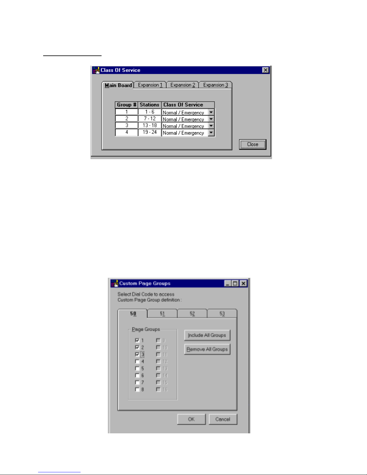
Default option of all stations, with or without the Option Board installed, is
Normal/Emergency.
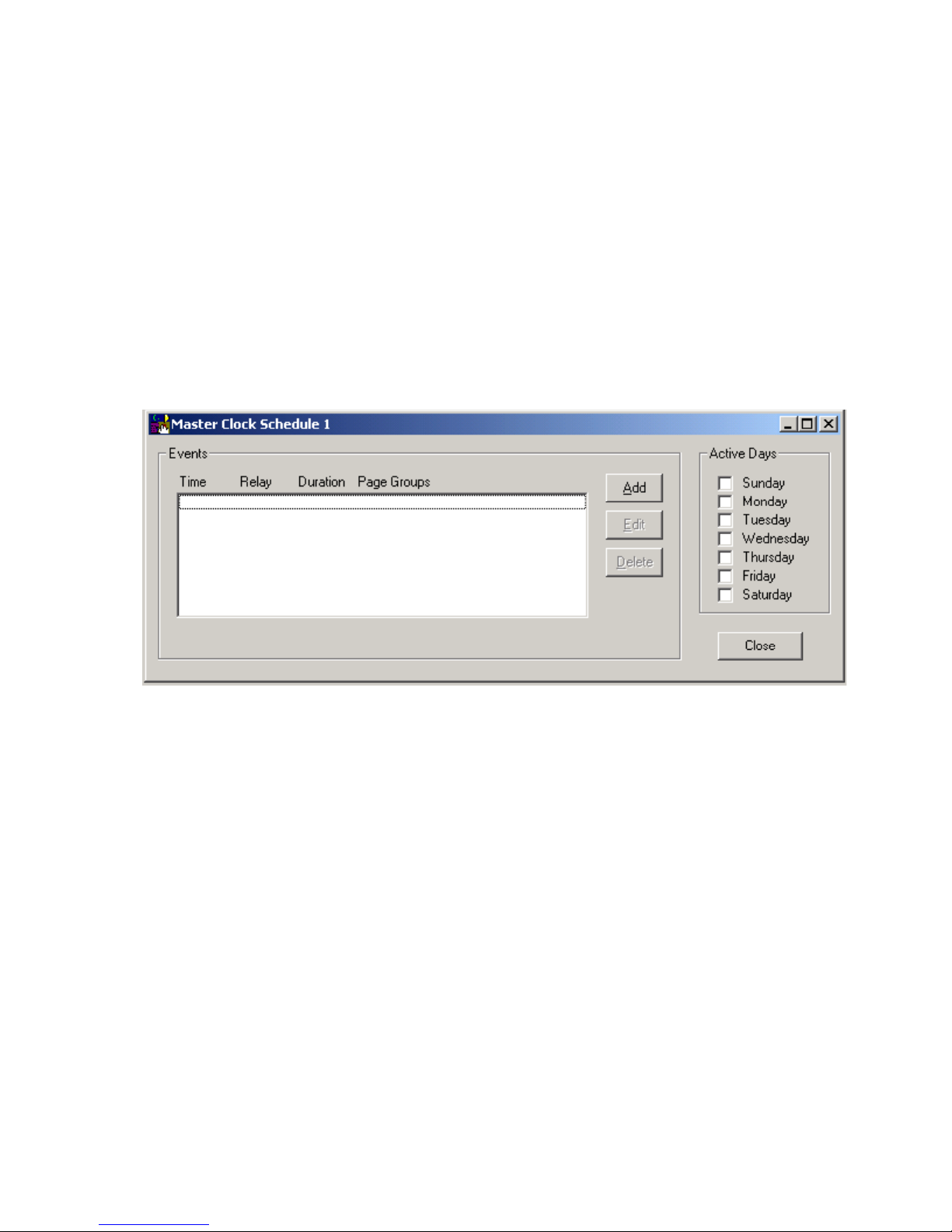
Custom Page Groups
When Custom Page Groups is selected, the following screen is displayed.
There are 4 Custom Page Groups available.
Select the Page Groups to receive custom paging by clicking on the desired box. Each Custom
Page Group can contain all groups or a combination of groups. (Example: Custom Page Group
50 could contain page groups 1, 2, and 3 and Custom Page Group 52 could contain page groups
1, 2, 7, and 8).
Select OK after all desired page groups are defined.
17 947226
Page 18
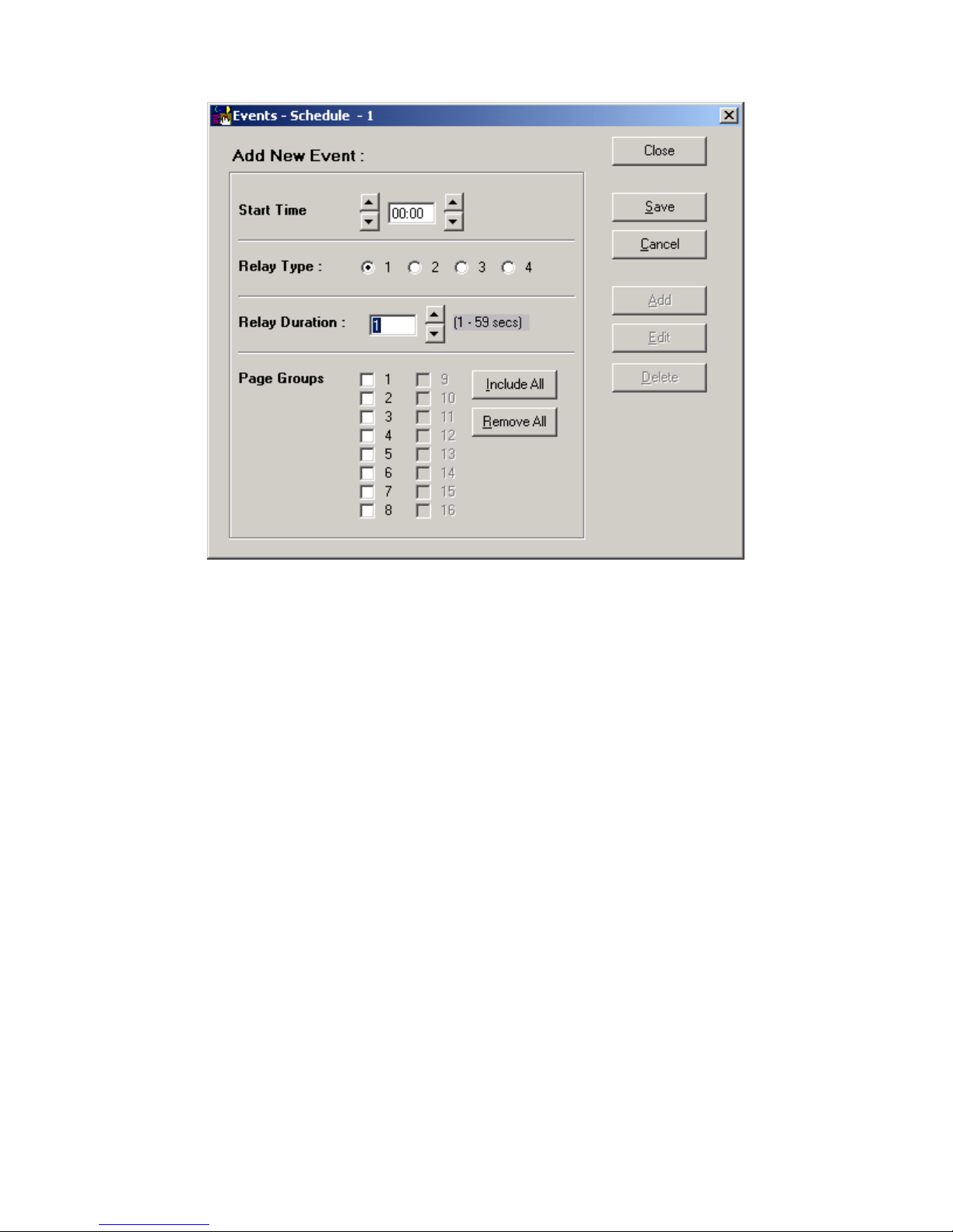
Master Clock Schedule
The Master Clock Schedule has 6 separate schedules with up to 256 total events. The user
defines how these events are to be distributed between schedules.
Dial codes may be used to force a schedule or to turn a schedule off. #94X forces schedule on
with the X being the number of the schedule (i.e. #941 will force Schedule 1). #940 turns off the
active schedule.
• Select Schedule 1-6.
• Click Open.
• Displays Schedule 1 menu.
• Choose which days schedule is to be active.
• Select Add.
New Event Screen menu will be shown. Select Start Time. Select which Relay Type you want
to follow the Schedule, and Select the Relay Duration of the contact closure. Select which Page
Group(s) tone should go to. Select Save.
NOTE: The contact closure pairs 13, 14, 15, 16 on the system punchdown block, should be
wired to the tone select input of an external tone generator (V-9927A). The tone output of the
external tone generator should then be wired to the external tone input of the VC-24, pair 5 of the
system punchdown block.
18 947226
Page 19
System
Next select System from the Programming Window. A check in the box means ON (selected);
an empty box means OFF (not selected). Select the desired options and click on OK to exit this
screen. The options are described in more detail in the Control Unit (VC-24) document or select
Help from the pull-down menu for on-screen details.
The Dip Switch button displays the dip switch equivalent (see next page) of the options selected
with the programming tool. Note that SW2 and SW3 are not used with the VC-24 System.
19 947226
Page 20
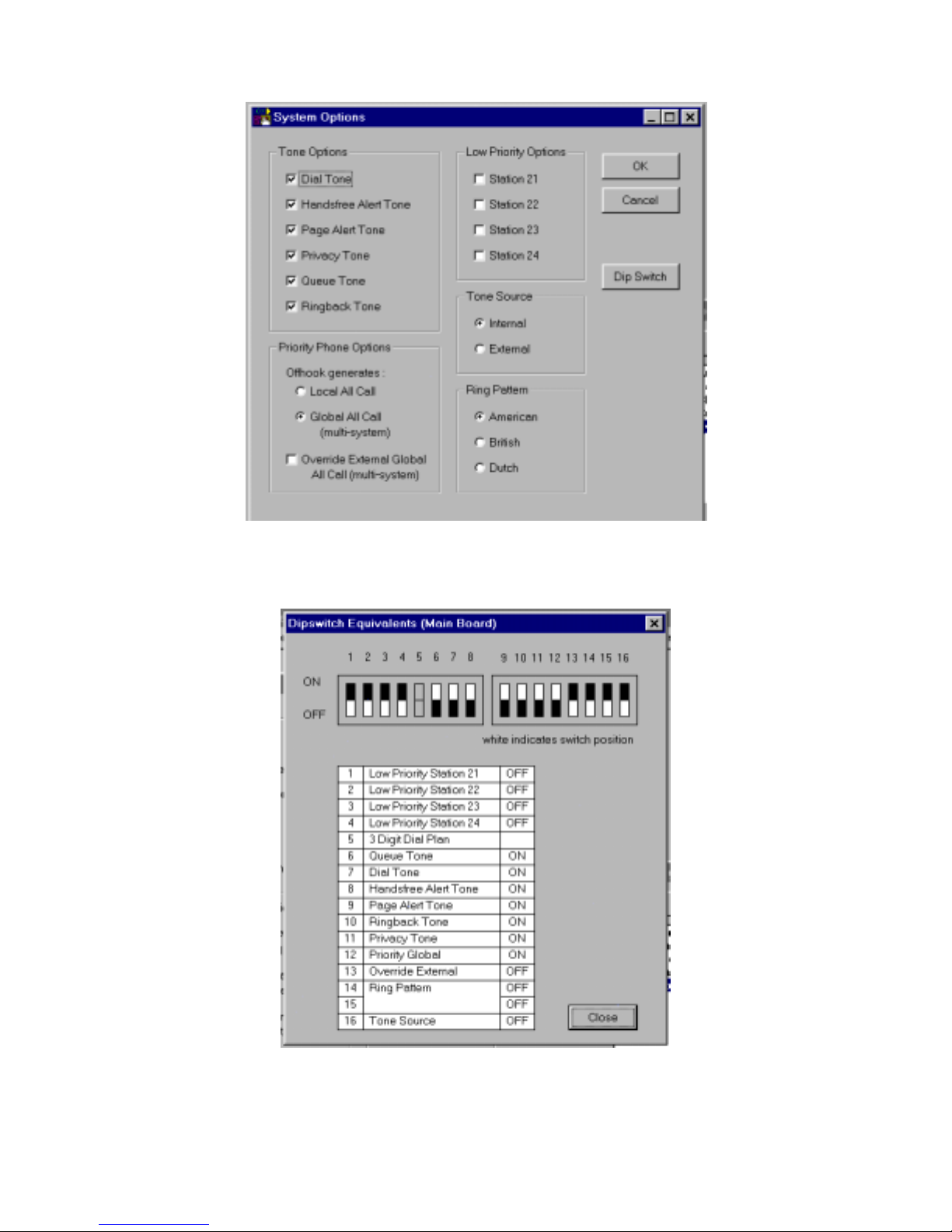
Dip switch equivalent of programmed options.
20 947226
Page 21
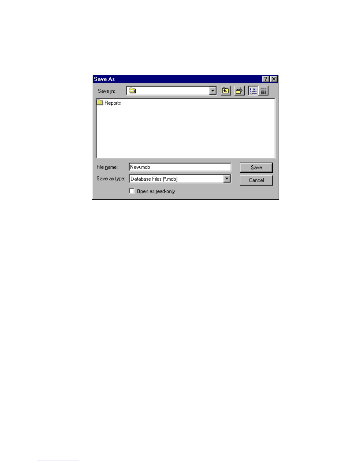
Save Programmed Data to a File
When the programming selections are complete, click on the File menu option to access the pulldown menu and select Save. Define fine name and location and press Save.
VC-24
A
COMMUNICATING WITH THE VC-24
Communicating with the VC-24 allows sending and receiving of user programmed data, Setting
of System Date and Time, and reading the revision numbers of the system firmware.
Once system programming is complete, this data must be downloaded to the VC-24 System.
This communication can be accomplished through two methods:
Initiating Communications
Direct Connect (PC is on site with the VC-24 System - can be accessed via RS232 cable).
To Connect:
Connect cable from the VC-24 to the PC being used.
Set up Com Port (see Set Up Com Port Section).
Connection complete.
Modem Connect (PC is off site or can only be accessed using phone lines to communicate).
To Connect:
Set up modem (See VCMDM user manual).
Set up Com Port (See Set Up Com Port Section).
Select Dialing Method
• Modem Connect
• Manual Connect
21 947226
Page 22
REMINDER:
For a modem to communicate with the VC-24, there must be a remote modem connected to
the VC-24. Refer to the VCMDM manual for details.
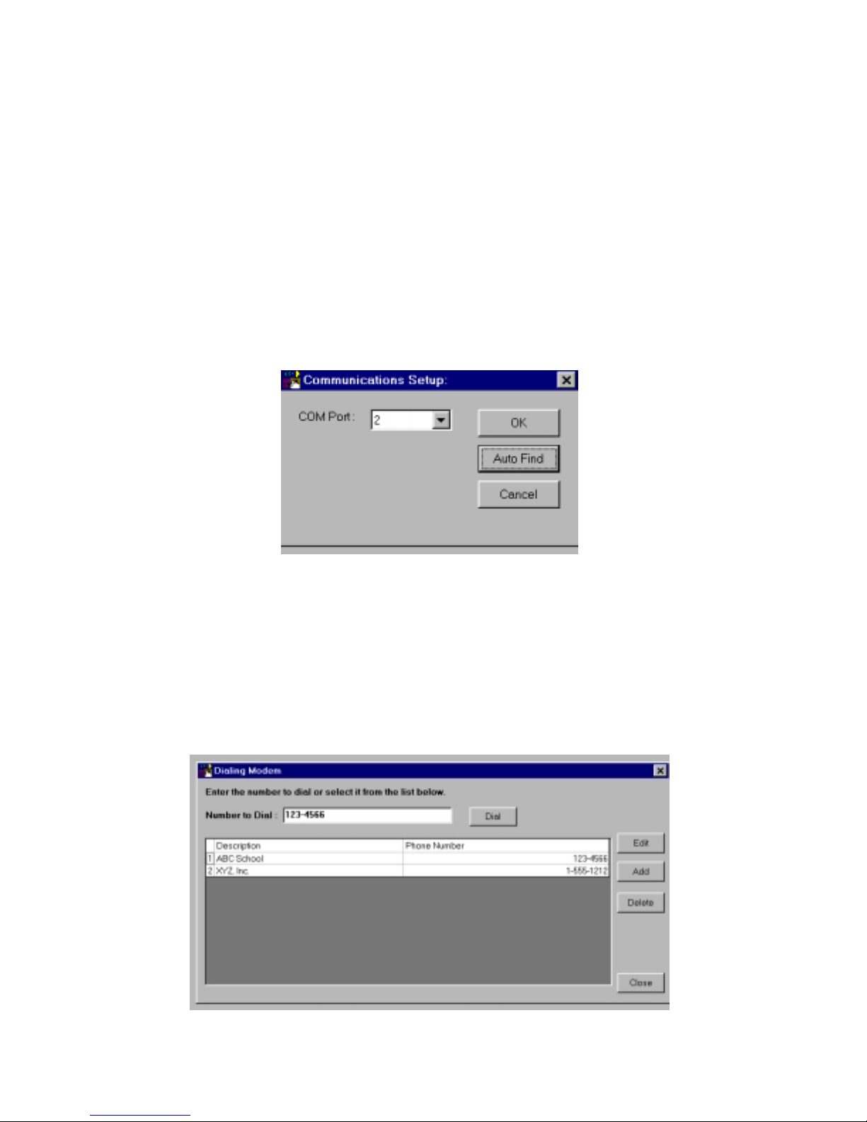
Direct Connect - Set Up Com Port
Select File, Com Setup, Com Port Selection.
If the port is known, use the down arrow to locate the number, select it and press OK.
If the port is not known, select Auto Find.
Reminder:
If direct connect is being used, make sure cables are connected and VC-24 is on.
If modem connect is being used, make sure modem is installed and working properly.
Modem Connect
From the Programming Tool, select File, Modem, and then Modem Connect.
The screen below appears. Enter the number to dial or select a phone number from the list displayed. Numbers can
be added, edited, or deleted from the list. Up to 10 numbers can be stored.
Once the desired phone number is displayed in the Number to Dial field, click on the Dial button. Messages should
be displayed stating, "Initializing", "Dialing", and "Modem Connection Successful". Click on OK.
If modem fails to connect, verify modem was set up properly during system installation. Refer to the VCMDM
manual.
22 947226
Page 23
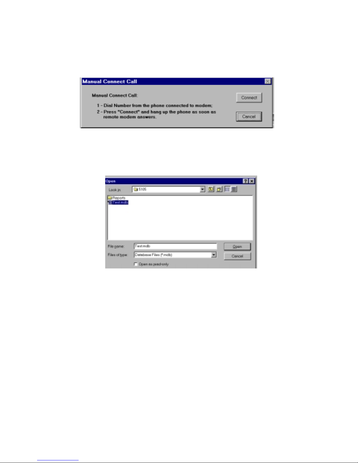
Manual Connect
From the Programming Tool, select File, Modem, and Manual Connect. Follow the
instructions as described on the screen. Messages should be displayed stating,
"Initializing","Dialing", and "Modem Connection Successful". Click on OK.
Send data to VC-24
From the main menu, select Send Data to VC-24. If a file is open, that file will be sent to the VC-24 System.
If no file is open when Send Data to VC-24 is selected, the screen appears to allow selection of the data file to be
opened and downloaded to the VC-24. Highlight the desired file and click on OK.
Receive Data from VC-24
From the main menu, select Receive Data from VC-24. This will take place automatically. If you are not allowed
to select Receive Data from VC-24, close the currently open file and try again. Messages will be displayed stating
Receiving Data, Receive Data Completed Successfully. Click on OK.
23 947226
Page 24
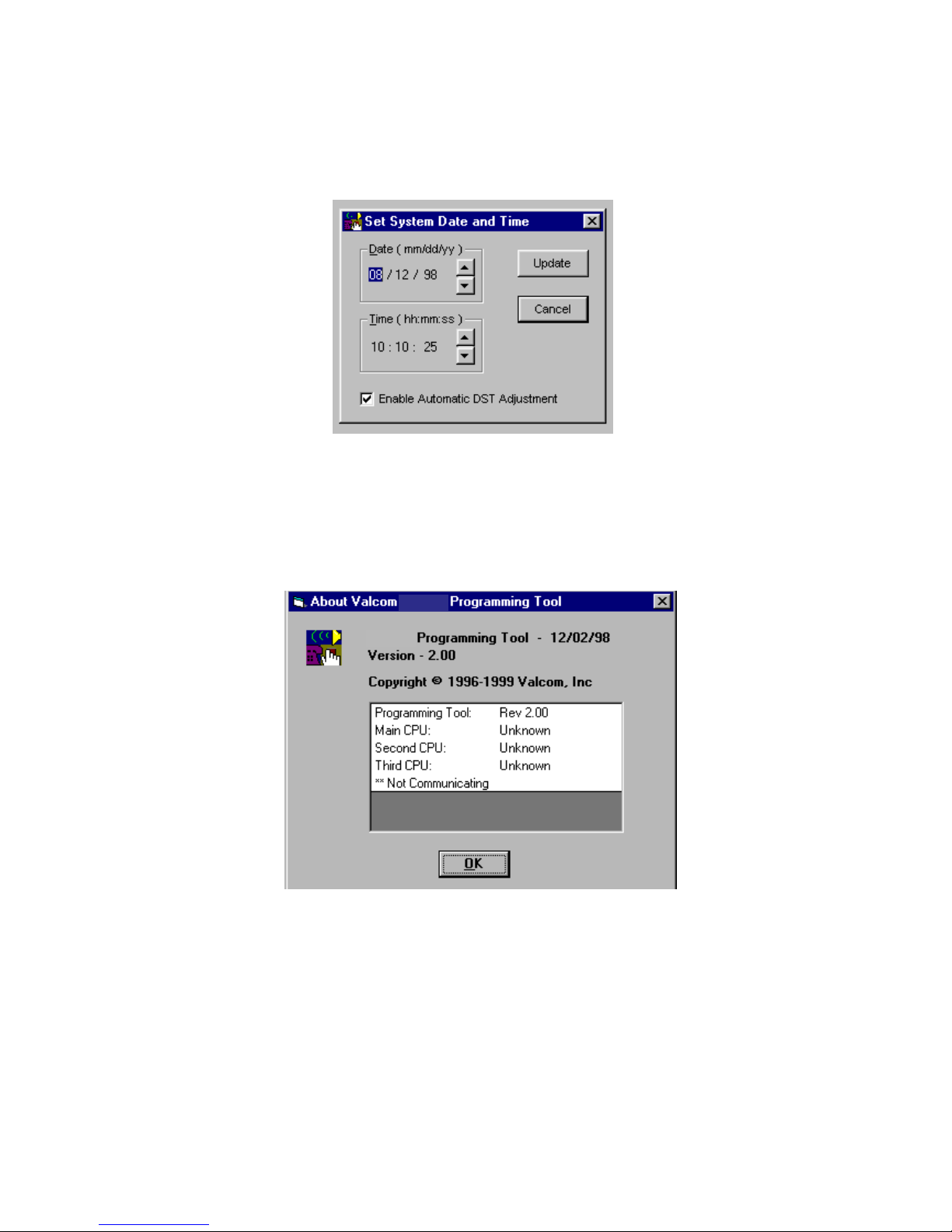
Set System Date and Time
Set System Date/Time by clicking on the Date/Time pull-down menu. Up/Down arrows are used to move date and
time to the desired setting. Press Update to set the new Date/Time or Cancel to leave unchanged . The Automatic
DST Adjustment can be enabled or disabled here.
Read Software and Firmware Revision Numbers
This feature is accessed through the Help menu. Select Help, then About. This option provides information for all
processors.
Reminder: The PC must be connected to the system to access this information.
VC-24
VC-24
Ending Communications
Direct Connect: No action requi red, just unplug cable.
Modem Connect: From the pulldown menu, select File, Modem, Modem Release.
24 947226
Page 25
MENU OPTIONS
PRINT
The print option allows the system to provide a hard-copy verification of how the system is
programmed. To print, the PC must be connected to a printer via the RS-232 serial printer port
(DB9 connector).
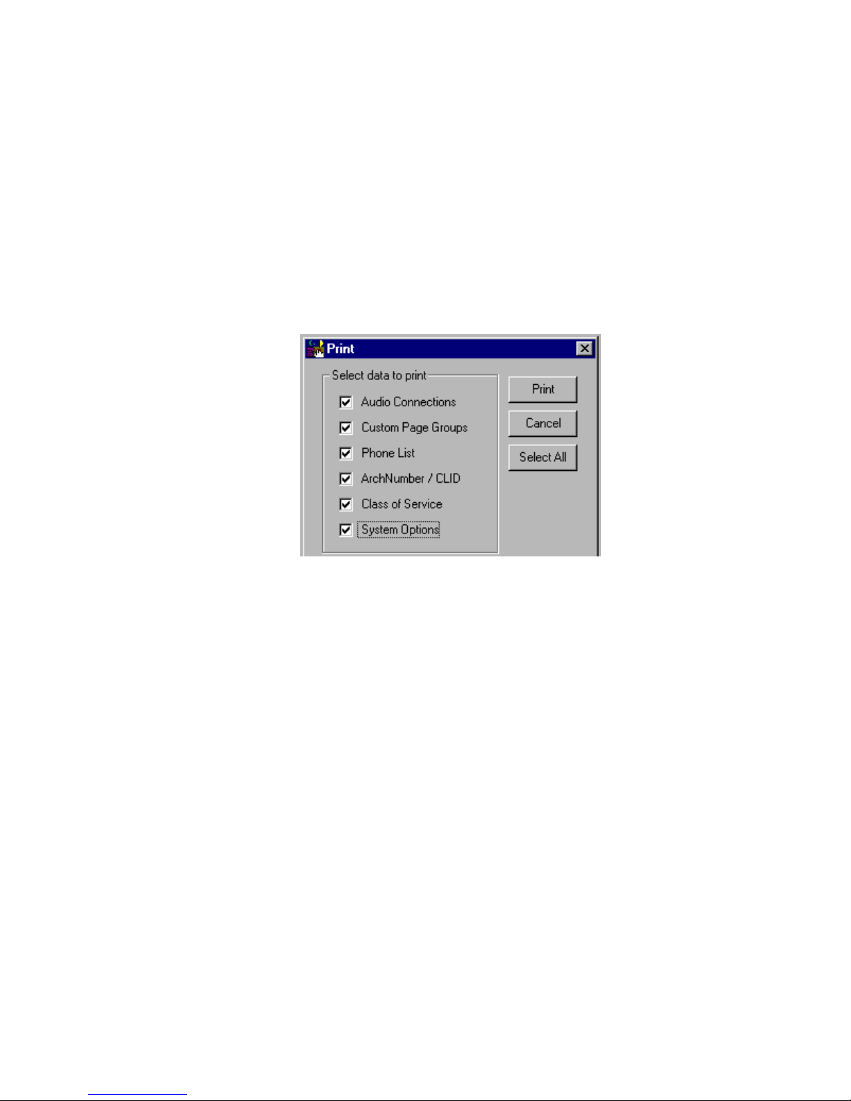
To access this option, select File and then Print. A screen (shown below) appears to allow
selection of all programmed options or individual options for printing.
This screen shows all items selected for printing.
WINDOW
The pull-down menu titled Window, allows several screens to be closed at once. Instead of
going through several open screens, closing them individually, select Window, Close All or
select the screens individually from the pull-down window.
HELP
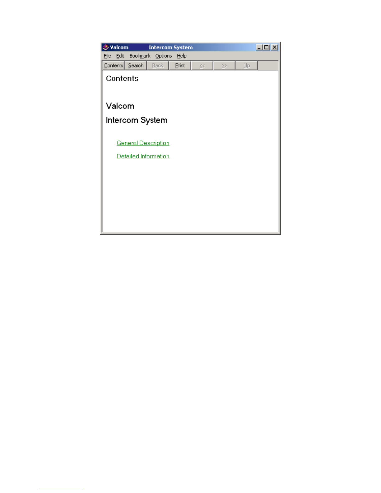
The Help pull-down menu provides on-screen definition of elements provided by the VC-24
Talkback Intercom System. Select Help, select Contents. Click on General Description or
Detailed Information to view the list of topics available through the Help menu.
25 947226
Page 26
V
VC-24
A
C-24
EXIT
Select Exit from the File pull down to close the Programming Tool.
26 947226
Page 27

OPERATION
Originate a Handsfree Page
• Lift handset, receive dial tone (default)
• Dial access code
• Hear alert tone (default) in handset and at
speaker
• Issue page
• Anyone hearing page c an reply handsfree by
speaker
• Hang up to terminate call
Originate a Group Page
• Lift handset, receive dial tone (default)
• Dial group page access code
• Hear alert tone (default) in handset and at
speaker
• Issue page
• Hang up to ter minate page
Originate a “Serial” Group Page
• Lift handset, receive dial tone (default)
• Press #60 and codes for groups to receive page
(attendant receives a single beep tone after each
group code; if an invalid group is dialed
attendant receives an error tone and is allowed to
re-enter the group)
• Press “*” to connect the page after last group is
dialed
• Hear alert tone (default) in handset
• Issue page
• Hang up to ter minate page
Originate an All Call Page
• Lift handset, receive dial tone (default)
• Dial the all call page code (#11 system all call;
#12 for external all call-multiple VC-24s)
• Hear alert tone (default) in handset
• Issue page (if multiple VC-24s are wired together
and the external all call page is dialed, the page
will be heard through all interco nnected VC-24s)
One-Way Page with Meet Me/Follow Me
Attendant makes an all call or group page to locate a
specific individual -
• Called person presses call button two times at
any talkback speaker (this cancels the page to all
other speakers and connects the attendant to the
answering speaker)
• Called person presses the call button of another
speaker included in the original page two times,
the call is disconnected from the active speaker
and reconnected at the new speaker.
• Handsfree alert tone notifies the attendant and
speaker location the Meet Me or Follow Me was
successful.
Inhibit
Allows the use of a single line phone (“A” lead
modified). When the phone goes offhook, all
handsfree, group, and/or all call pages are cancelled
and the phone is connected to the attendant.
Override Page Port
When a phone connected to the override page port
goes offhook, it is immediately connected to all
speakers for a one-way page. Any existing handsfree
or one-way pages will be placed at the top of the
queue for reconnection when the priority phone
releases. The attendant phone receives a repeat beep
tone alerting of an override.
Queue Operation
Attendant phone is in use and another call is placed
from a speaker location, the phone and connected
speakers receive a queued call tone (single or triple
beep tone), and the call is placed in the queue.
Pressing the “#” key twice while on a call with one or
more queued calls, will disconnect the current call
and connect the attendant to the next call in the
queue. If the attendant hangs up while calls are in the
queue, the phone will ring and the next call in the
queue will be connected when the phone is answered.
Queued calls will be accessed in the order received
with a maximum of 20 calls being in the queue at one
time. If the queue is full, additional calls are ignored
unless the last queued call has a lower priority than
the incoming call in which case the lower priority call
will be replaced in the last position by the new call.
Placing a Call from a Speaker
• Press call button, attendant phone rings
• Attendant answers, phone and speaker are
connected through handsfree circuit
• Hear alert tone in handset and at speaker
• Person at speaker converses handsfree to
attendant
• Attendant must hang up to terminate call
Placing a Call from a Door Box
• Press door button, attendant phone rings
• Attendant answers, phone and speaker are
connected through handsfree circuit
• Hear alert tone in handset and at speaker
• Person at speaker converses handsfree to
attendant
• Attendant unlocks door by pressing “*” key
twice while connected to door speaker (door
speaker must be connected to one of the last four
zones of the main board making the door unlock
feature available.)
• Attendant must hang up to terminate call.
27 947226
Page 28
Remote Station Access - Call Button
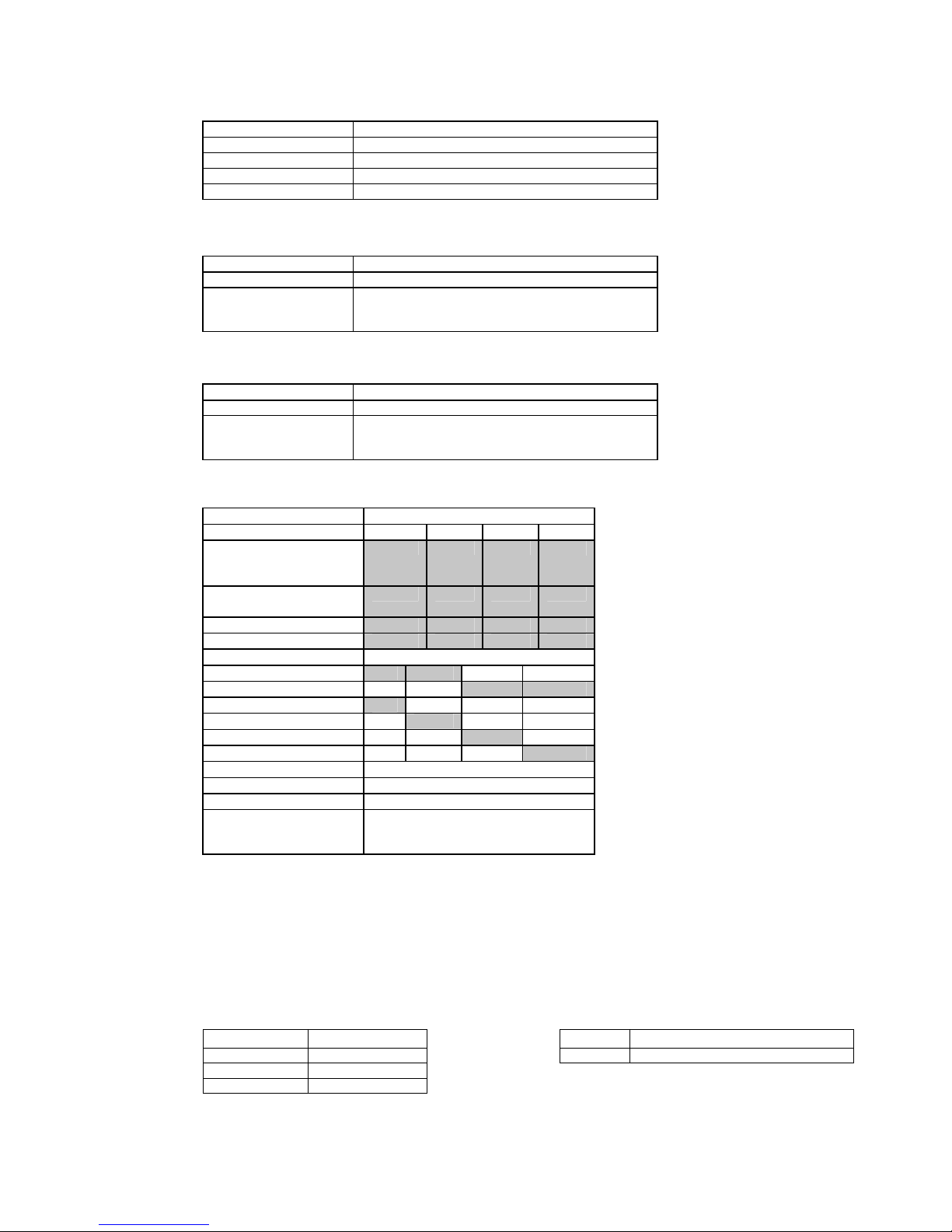
Button Presses Function
1 press Originate call to attendant
2 presses Meet-Me / Follow-Me if appropriate (see definitions)
3 presses Ignored
4 or more presses Originate emergency cal l to attendant
Attendant Station Dialing Plan
2 Digit Zone Access to Individual Stations:
Dial Code Function
10..33 Handsfree speakers - Main board
"**" during hf to
zone 30,31,32, or 33
(Station 1 = code 10, stati on 2 = code 11, ……station 24 = code 33)
Operate relay for longer of 2.5 seconds or duration
of second press; operation may be repeated as
long as connected.
3 Digit Zone Access to Individual Stations:
Dial Code Function
101..124 Handsfree speakers - Main board
"**" during hf to zone
121, 122, 123, or 124
Operate relay for longer of 2.5 seconds or duration
of second press; operation may be repeated as
long as connected.
(Station 1 = code 101, stati on 2 = 102, ….. station 24 = code 124)
Page Codes
Dial Code Groups
#10
external all call
(multiple VC-24s)
#11
system all call
#12
#14
#60
#61
#62
#70
#71
#72
#73
#92
#93
“*” during 1-way page
“##” during any
connected call
1 2 3 4
(Example: #60 + 71 + 73 + *)
Mute page while waiting f o r “M eet Me”
Disconnect current c al l connect to
next queued call or receive dial t one i f
Set Time h h :mm:ss
Cancel Emergency Tone
none queued.
#60 - Serial Group Call - User may sel ect any combination of page codes during dialing. Group 10 (External All Call) is not a valid
code selection when using these dial codes.
The attendant may dial a new zone or group during a conversation. The current conversation will be disconnected and the new
request connected without the attendant needing to return to dial tone.
NOTE:
For Group page selection and Background Music Programming: BGM Dialcodes:
Group 1 Stations 1 – 6 #960 Background Music OFF
Group 2 Stations 7 – 12 #961 Background Music ON
Group 3 St at i ons 13 – 18
Group 4 Stations 19 - 24
28 947226
Page 29
TROUBLESHOOTING CHART
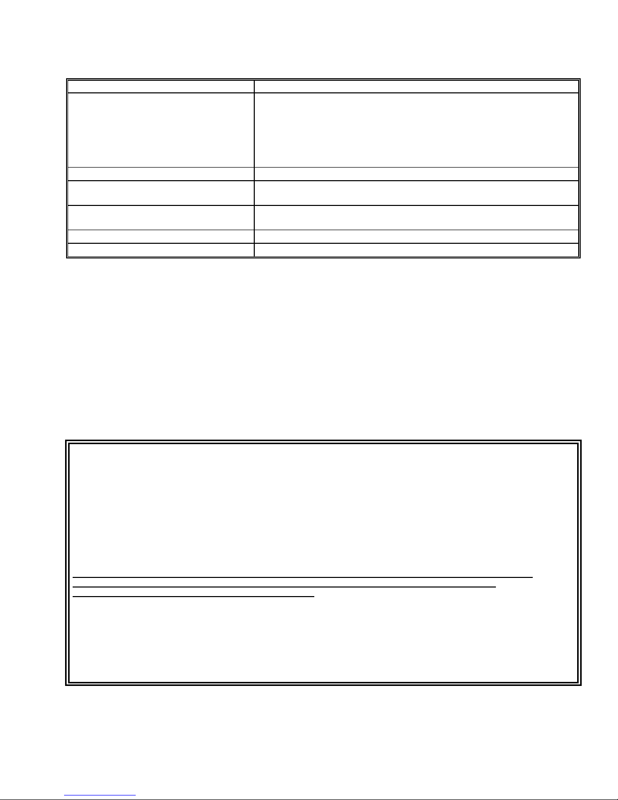
Problem Corrective Action
No system operation.
• Verify AC voltage is present at the receptacle.
• Check the fuse located on the bottom of the unit. If blown, replace with
a 1 amp, 250 Vac fuse.
• Verify that 25 pair cable connectors are completely plugged i nt o circuit
board connectors.
• Refer to Figure 1 and verify all connections.
No paging at speaker.
Paging at speaker but no reply from
• Refer to Figure 1 and adjust volume.
• Refer to Figure 1 and adjust volume.
speaker.
No system ringing when call button is
• Verify all associated connections.
pressed.
Background music not heard at speakers.
No dial tone.
• Verify connection of speakers and background music input.
• Refer to programming.
TECHNICAL ASSISTANCE
When trouble is reported, verify there are no broken connections. Assistance in troubleshooting is available from the
factory. Call (877) 427-2166 and ask for Technical Support.
Valcom equipment is not field repairable. Valcom, Inc. maintains service facilities in Roanoke, VA. Should
repairs be necessary, attach a tag to the unit clearly stating company name, address, phone number, contact person,
and nature of the problem. Send the unit to:
Valcom, Inc.
Repair & Return Dept.
5614 Hollins Road
Roanoke, VA 24019-5056
TM
Valcom, Inc. warrants i ts products to be free from defects in material s and workmanship under conditions of normal use and
Class Connection
Service for a period of two years from the date of shipment. The obli gation under this warranty shall be limi t ed to the replacement,
repair or refund of any such defect i ve devi ce within the warranty period, provided that:
1. inspection by Valc om, Inc. indicates the validity of the claim,
2. the defect is not t he result of damage, misuse, or negligence after the original shipment,
3. the product has not been altered i n any way or repaired by others and that factory sealed units are unopened
(A service charge plus parts and labor will be applied to units defaced or physically damaged),
4. freight charges for the ret urn of products to Valcom are prepai d,
5. all units 'out of warranty' are subject to a servic e charge. The service charge will cover minor repairs
(Major repairs will be subject to additional charges for parts and labor).
This warranty is in lieu of and excludes all other warranties, expressed or implied, and i n no event shal l Valcom, Inc. be
liable for any anticipated profits, consequential damages, loss of time or other losses incurred by the buyer in
connection with the purchase, operation or use of the product.
This warranty specifically excludes damage incurred in shipment. In the event a product is received in damaged condition, the
carrier should be notified immediately. Claim s for such damage should be fi l ed with the carrier involved in accordance with the
F.O.B. point.
Roanoke, VA 24019-5056
877-427-2166 / FAX: 540-362-9800
LIMITED WARRANTY
Headquarters:
Valcom, Inc.
5614 Hollins Rd
29 947226
Page 30

Glossary of Terms
(Numbers in parenthesis are the pin outs on P7 connection block required for this feature)
Attendant Port (26/1)
key system C. O. line position, or PABX loop start trunk port is required for access.
Background Music Input (28/3)
Clock Activate (31/6)
Clock C. C. (32/7)
Clock Sync (45/20)
Common Audible C. C. (27/2)
Dry Priority Activate (36/11)
Emergency Activate (33/8)
Emergency C. C. (34/9)
External Tone Input (30/5)
Global All Call Activate (43/18)
broadcast to all interconnected systems.
Global Page Link (44/19)
pages to be broadcast to all interconnected systems.
Global Priority Activate (42/17)
broadcast to all interconnected systems.
Inhibit (37/12)
and a 5.1K ohm resistor is required. The tip and ring of the telephone connects to the W/BL (26/1) pair, the “A1”
lead connects to GND (O/BK, pin 12) , the “A” lead has the 5.1K ohm resistor placed in series and the resistor
terminates on Inhibit (BK/O, pin 37).
Night Ring Activate (46/21)
is detected on this pair.
Override Page Port (35/10)
PABX loop start trunk port, electronic key system C. O. line position or page po rt with contact closure is required
for access. All other system activities are suspended while the override page port is active.
Riot Mode (29/4)
mode enabled).
Station 21 C. C. (47/22),
closure to activate door strike plate from attendant port. Enabled when “*” is pressed twice after communication has
been established between attendant port and station.
- Primary system access is achieved on this pair. A dedicated single line telephone, electronic
- Input for low level music source (i.e., V-2952).
- Input to enable tone source for system broadcast.
- Contact closure output follows clock activate to enable external tone source.
- Input to reset system time to 0200 hours.
- Provides contact closure when attendant station is signalled - follows ring pattern.
- Input to enable priority page port when used with telephone system page port.
- Input to enable external tone source for system broadcast.
- Contact closure follows emergency activate to enable external tone source.
- Input for low level tone source (i.e., V-9927A).
- Control pair for use with multiple VC-24 systems that require all call pages to be
- Audio pair for use with multiple VC-24 systems that require all call and/or priority
- Control pair for use with multiple VC-24 systems that require priority pages to be
- If a single line telephone is desired for “Meet Me Answer” a single line “A” lead control telephone
- Input to enable night ringing to be broadcast throughout system when contact c l osure
- Secondary system access is provided on this pair. A dedicated single line telephone,
- Input to allow attendant port to receive only emergency calls (open - normal mode; closed - riot
Station 22 C. C. (48/23), Station 23 C. C. (49/24), Station 24 C. C. (50/25) - Contact
30 947226
 Loading...