

Page 1
Page 2

Page 3

0Index
1. General Information and Safety instructions ....................... 2
1.1.0 Scope and contents of the manual . . . . . . . . . . . . 2
1.1.1 How to store the manual . . . . . . . . . . . . . . . . . . . . . 2
1.2.0 Manufacturer's address . . . . . . . . . . . . . . . . . . . . . 2
1.3.0 Working conditions . . . . . . . . . . . . . . . . . . . . . . . . . . 2
1.3.1 Intended use . . . . . . . . . . . . . . . . . . . . . . . . . . . . . . . 2
1.3.2 Improper Use . . . . . . . . . . . . . . . . . . . . . . . . . . . . . . . 2
1.4.0 Safety legislation . . . . . . . . . . . . . . . . . . . . . . . . . . . 2
1.4.1 General safety requirements . . . . . . . . . . . . . . . . . 2
1.5.0 Protection devices . . . . . . . . . . . . . . . . . . . . . . . . . . 3
1.5.1 Personal protective equipment . . . . . . . . . . . . . . . 3
1.5.2 Safety signs . . . . . . . . . . . . . . . . . . . . . . . . . . . . . . . . 3
1.6.0 Residual risks . . . . . . . . . . . . . . . . . . . . . . . . . . . . . . 3
2. Machine description .............................................................4
2.1.0 Technical features . . . . . . . . . . . . . . . . . . . . . . . . . . 4
2.2.0 BD LASER MAX main features . . . . . . . . . . . . . . . . 4
2.2.1 Machine accessories . . . . . . . . . . . . . . . . . . . . . . . . 4
2.2.2 Parts- Machine . . . . . . . . . . . . . . . . . . . . . . . . . . . . . 5
2.3.0 Jaws supplied with the machine . . . . . . . . . . . . . . 5
3. Transport and installation ....................................................6
3.1.0 Packaging . . . . . . . . . . . . . . . . . . . . . . . . . . . . . . . . . 6
3.1.1 Opening the package . . . . . . . . . . . . . . . . . . . . . . . . 6
3.2.0 Transport . . . . . . . . . . . . . . . . . . . . . . . . . . . . . . . . . . 6
3.2.1 Unloading and handling the machine . . . . . . . . . . 6
3.3.0 Temporary storing . . . . . . . . . . . . . . . . . . . . . . . . . . . 6
3.3.1 Characteristics of the place of installation . . . . . 6
3.3.2 Temperature and humidity . . . . . . . . . . . . . . . . . . . 6
3.3.3 Working environment . . . . . . . . . . . . . . . . . . . . . . . . 6
3.3.4 Lighting . . . . . . . . . . . . . . . . . . . . . . . . . . . . . . . . . . . 6
3.4.0 Connections . . . . . . . . . . . . . . . . . . . . . . . . . . . . . . . 6
3.4.1 Grounding . . . . . . . . . . . . . . . . . . . . . . . . . . . . . . . . . 6
4. Start up ................................................................................7
4.1.0 Notice for machine use . . . . . . . . . . . . . . . . . . . . . . 7
4.1.1 Preliminary controls and setup . . . . . . . . . . . . . . . 7
4.2.0 Starting the consolle . . . . . . . . . . . . . . . . . . . . . . . . 7
4.3.0 Language setting . . . . . . . . . . . . . . . . . . . . . . . . . . . 7
5. Setup ....................................................................................8
5.1.0 Main Menu . . . . . . . . . . . . . . . . . . . . . . . . . . . . . . . . . 8
5.1.1 Search by car brand . . . . . . . . . . . . . . . . . . . . . . . . . 8
5.1.2 Search by code . . . . . . . . . . . . . . . . . . . . . . . . . . . . . 8
5.1.3 Search by article . . . . . . . . . . . . . . . . . . . . . . . . . . . . 9
INDEX
5.2.0 Setup Menu . . . . . . . . . . . . . . . . . . . . . . . . . . . . . . . .9
5.3.0 Calibrations Menu . . . . . . . . . . . . . . . . . . . . . . . . . . .9
5.3.1 Cutter Setup . . . . . . . . . . . . . . . . . . . . . . . . . . . . . . .10
5.3.2 Jaw Setup . . . . . . . . . . . . . . . . . . . . . . . . . . . . . . . . . 10
5.4.0 Update . . . . . . . . . . . . . . . . . . . . . . . . . . . . . . . . . . .10
5.4.1 Keyonline Update . . . . . . . . . . . . . . . . . . . . . . . . . . 11
5.4.2 Keyonline via PC Update . . . . . . . . . . . . . . . . . . . . .11
5.4.3 Special . . . . . . . . . . . . . . . . . . . . . . . . . . . . . . . . . . .12
6. Key search ......................................................................... 13
6.1.0 Search menu . . . . . . . . . . . . . . . . . . . . . . . . . . . . . .13
6.1.1 Search by record number . . . . . . . . . . . . . . . . . . . . 13
6.1.2 Search by code . . . . . . . . . . . . . . . . . . . . . . . . . . . .13
6.1.3 Search by card . . . . . . . . . . . . . . . . . . . . . . . . . . . . .13
6.1.4 Search by cylinder brand . . . . . . . . . . . . . . . . . . . .14
6.1.5 Search by motorbike brand . . . . . . . . . . . . . . . . . . 14
6.1.6 Search by car brand . . . . . . . . . . . . . . . . . . . . . . . .14
6.1.7 Search by article . . . . . . . . . . . . . . . . . . . . . . . . . . .14
6.2.0 Bookmarks list . . . . . . . . . . . . . . . . . . . . . . . . . . . . . 14
7. Modify and cut ................................................................... 15
7.1.0 Decode . . . . . . . . . . . . . . . . . . . . . . . . . . . . . . . . . . .15
7.2.0 Code . . . . . . . . . . . . . . . . . . . . . . . . . . . . . . . . . . . . . 15
7.3.0 Direct . . . . . . . . . . . . . . . . . . . . . . . . . . . . . . . . . . . .15
7.4.0 Key modify menu . . . . . . . . . . . . . . . . . . . . . . . . . . . 16
7.5.0 Key cut menu . . . . . . . . . . . . . . . . . . . . . . . . . . . . . .16
8. Archive, PC and user menu ................................................. 17
8.1.0 Archive Menu . . . . . . . . . . . . . . . . . . . . . . . . . . . . . . 17
8.2.0 PC Menu . . . . . . . . . . . . . . . . . . . . . . . . . . . . . . . . . .17
8.3.0 User Menu . . . . . . . . . . . . . . . . . . . . . . . . . . . . . . . . 17
9. Maintenance, Dismantling and disposal ............................ 18
9.1.0 General information . . . . . . . . . . . . . . . . . . . . . . . .18
9.1.1 Skills of maintenance personnel . . . . . . . . . . . . . .18
9.1.2 Type of Maintenance . . . . . . . . . . . . . . . . . . . . . . . . 18
9.2.0 Ordinary maintenance . . . . . . . . . . . . . . . . . . . . . . 18
9.2.1 Checking and cleaning the fan . . . . . . . . . . . . . . .18
9.2.2 Cleaning the working area . . . . . . . . . . . . . . . . . . . 18
9.2.3 Cleaning the display . . . . . . . . . . . . . . . . . . . . . . . .18
9.2.4 Replacing the milling cutter . . . . . . . . . . . . . . . . .18
9.2.5 Replacing the fan . . . . . . . . . . . . . . . . . . . . . . . . . .19
9.2.6 Replacing the startup unit . . . . . . . . . . . . . . . . . . . 19
9.2.7 Inspecting and replacing the fuses . . . . . . . . . . . 20
9.2.8 Replacing the motor belt . . . . . . . . . . . . . . . . . . . . 20
9.2.9 Replacing the X axis sensor . . . . . . . . . . . . . . . . . 20
9.2.10 Replacing the Y axis sensor . . . . . . . . . . . . . . . . . 21
9.2.11 Replacing jaw parts . . . . . . . . . . . . . . . . . . . . . . . . 22
9.3.0 Waste disposal . . . . . . . . . . . . . . . . . . . . . . . . . . . . 22
9.4.0 The WEEE directive . . . . . . . . . . . . . . . . . . . . . . . . 22
9.4.1 Disposal of the packing material . . . . . . . . . . . . . 22
ENGLISH
Class C Solutions Group BD LASER MAX Man. cod. B409652FG 1
Page 4

GENERAL INFORMATION AND SAFETY
1
2
4
7
5
3
6
INSTRUCTIONS
ENGLISH
1General Information and Safety instructions
Glossary
01. Head
02. Neck
03. Shoulder
04. Blade
05. Tip
06. Back
07. Bitting
Laser-Style keys Such keys are called “Laser” on account of
their special bitting style across the profile.
Key sample The “original” key from which, through bit-
Key blank A key with no engraving that is cut following
ting, a duplicate key is obtained.
the profile of the key sample.
The user's and maintenance manual of the “BD LASER MAX” for the
duplication of Laser keys, contains all operation instructions on the
best way to use the machine while guaranteeing the safety of operators.
1.1.0 Scope and cont ent s of the m anua l
This manual provides basic information on the installation, operation
and maintenance of the key duplicating machine.
Users must follow the instructions contained in this manual scrupulously, especially those concerning safety norms and ordinary maintenance.
1.1.1 How t o st ore the m anu al
The manual must always be kept with the machine it refers to.
The manual must be stored in a safe place, away from dust and moisture and it must be accessible to all users who shall consult it any
time they are in doubt on how to operate the machine.
1.2.0 Manufacturer's address
Class C Solutions Group
CLEVELAND, OH
1-866-267-6776
OPTION #2
Website: www.mscdirect.com/ClassCSolutions
E-mail: [email protected]
To facilitate communication please state:
- the name of the customer;
- the name of the customer.
1.3.0 Working conditions
1.3 .1 Inte nded use
The key cutting machine described in this manual has been designed
for the electronic code cutting and duplication of Laser-type keys,
using special adaptors.
1.3.2 Improper Use
The improper use of the machine includes using the tool to perform an
operation that it was not intended for. Should this occur the manufacturer shall take no responsibility for damage to materials or persons
and shall consider all warranties on the machine void.
1.4.0 Safety legislation
The key duplicating machine and its safety devices comply with macchine Council Directive 2006/42/EEC known as “Machine Directive“.
When employed for their intended use all machines marked CE comply with EU 'machine' directive 2006 /42/EEC known as “Machine Di-
rective“ and directives 2006/95/EEC, 2004/108/EEC.
Warning: Important!
Users must be informed about the instructions contained in the following screens.
Users must carefully follow the instructions contained
in this manual.
1.4.1 General safety requirements
Warning: Important!
Make sure that the grounding system is well
connected.
Always unplug the machine (turn off the main switch)
before servicing mobile parts that are electrically
operated.
Do not pour water or other liquids onto electrical cables
and connections.
2 BD LASER MAX Man. cod. B409652FG Class C Solutions Group
Page 5
GENERAL INFORMATION AND SAFETY
D
C
A
B
INSTRUCTIONS
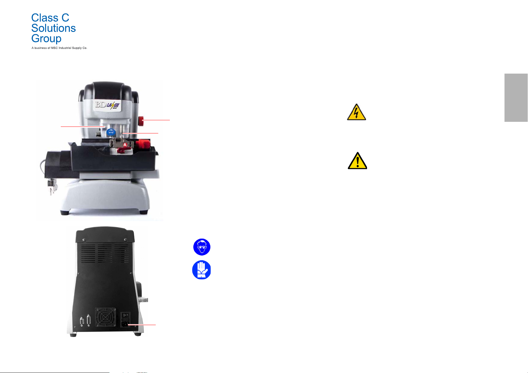
1.5 .0 Pro tec tio n dev ice s
a. Ground Connection
b. Protective eye guard
c. Emergency Button
1.5.1 Personal protective equipment
When operating and maintaining the key cutting machine users must
wear the following personal protective equipment:
Protective clothing Maintainers and key cutting machine operators
Safety glasses During key cutting operations operators must
Gloves If milling cutters are present, operators must
1.5 .2 Safe ty s ign s
The key cutting machine bears the following safety signs.
must wear protective clothing that complies
with the basic safety requirements currently in
force.
In case of slippery floors users must wear safety shoes with anti-slip soles.
wear eye protection (glasses or goggles).
wear protective gloves to avoid injuries.
- Wear safety glasses.
1.6 .0 Res idua l ri sks
When operating the machine the following residual risks - as well as
those connected with its use - must be taken into due consideration:
• Electrical hazard (A)
Since the machine is equipped with electrical devices, in case of faults there might be a risk of
electrocution. The power line must be fitted with
the appropriate control and protection devices (circuit breaker, thermal overload switch and differential switch).
• Mechanical hazard (D)
The machine is fitted with milling cutters used in
key cutting operations. Operators must watch out
to avoid cutting their hands when they are cutting
keys or changing tools.
ENGLISH
- Wear safety gloves.
Class C Solutions Group BD LASER MAX Man. cod. B409652FG 3
Page 6
MACHINE DESCRIPTION
ENGLISH
2Machine description
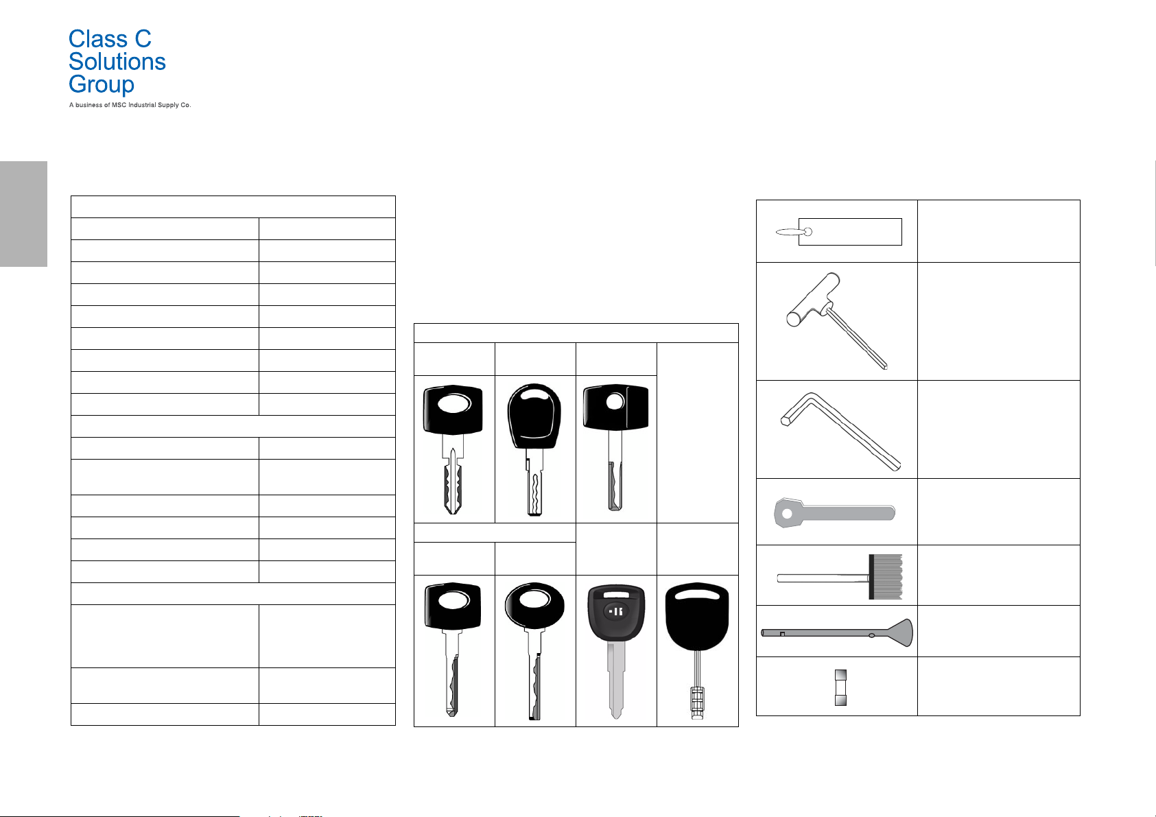
2.1.0 Technical features
Dimensions
Width 300 mm
Height 360 mm
Depth (Length) 360 mm
Weight 16,5 Kg
Dimensions Console
Width 200 mm
Height 150 mm
Depth (Length) 50 mm
Weight 0,8 Kg
Technical features
Power voltage 110/250 V 50/60 Hz
Absorption 125 W (machine) - 35W
(Stand By)
Motor Brushless 6000 rpm
Type o f c utter Ing carbide
Operating temperature 0° / + 40°C
Acoustic pressure level L
(A) 78,5 dB(A)
p
User Interface
Type 7” industrial colour touch
screen, 16:10, resolution
800x480 px, incorporated
CPU
Input / Output 2 USB 2.0 ports; 2 RS232
serial ports; 1 LAN port
CPU ARM Cortex A8
2.2.0 BD LASER MAX main features
Professional
BD LASER MAX
key cutting machines are electronic devices able to facilitate the duplication of a variety of keys that require the
use of fixed adaptors.
The BD LASER MAX has an aluminum body that reduces vibration
while guaranteeing noiseless operation and a longer cutter life.
The key cutting machine BD LASER MAX is used to duplicate the
following types of keys:
Laser-type keys
4 External
cuts
Laser-type keys with thin stem
Double exter-
nal bitting
Double inter-
nal bitting
Double exter-
nal bitting
Double exter-
nal bitting
Double bit-
ting flat keys
Tibbe-Ford
keys
2.2.1 Machine accessories
Jaw calibrating templates -994
Code RIC03444B
T- Handle hexagon wrench (long)
2,5mm
Code RIC03442B
T- Handle hexagon wrench (long)
3mm
Code RIC03440B
Hexagonal keys
Code RIC03438B
Setup blanks
Code RIC03448B
Brush
Code RIC03446B
Cutter insertion tool-994
Code RIC03436B
1 pc. - Rapid fuse 4A 5x20
Code RIC02592B
4 BD LASER MAX Man. cod. B409652FG Class C Solutions Group
Page 7
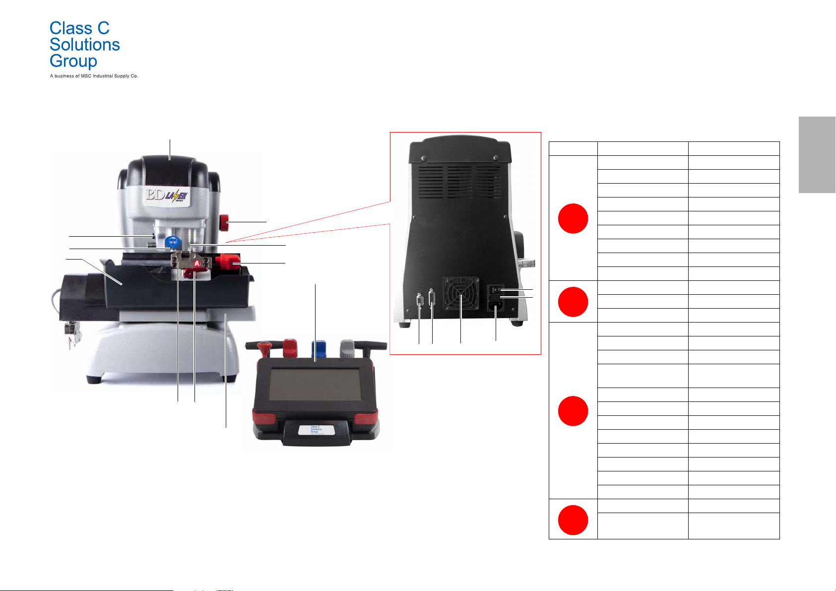
2.2.2 Parts- Machine 2.3.0 Jaws supplied with the machine
12
8
4
16
11
5
10
9
76
17
1314
15
2
1
3
1. Main switch
2. Power connection
3. Fuses holder
4. Tracer holder
5. Cutter
6. Jaw
7. Le v e rs to l oc k j aw
8. Levers to clamp jaw
9. Jaw support carriage
10. Container to collect waste
11. Protective eye guard
12. Emergency button
13. Serial port (RS232)
14. Input / Output
15. Fan filter
16. Patent pending
17. Console
ABC
D
Class C Solutions Group BD LASER MAX Man. cod. B409652FG 5
MACHINE DESCRIPTION
Jaw Car brands Key-system
Honda 4 External Track
Gm - Pontiac - GTO 2 External Track
Mercedes 4 External Track
Volvo 4 External Track
Volvo (V50 2004) 2 External Track
Saab 2 External Track
Vauxhall (U.K.) 2 External Track
Ford (U.K.) 2 External Track
Subaru - Outback 4 External Track
BMW 4 External Track
Volvo 2 External Track
Peugeot 4 External Track
Volkswagen 2 Inside Track
Audi 2 Inside Track
Lexus 4 Inside Track
Kia (Amanti: US +
Oprius: UK)
BMW 2 Inside Track
Saab 4 Inside Track
Porsche 2 Inside Track
Scoda (U.K.) 2 Inside Track
Seat (U.K.) 2 Inside Track
Vauxhall (U.K.) 2 Inside Track
Ford (U.K.) 2 Inside Track
Mazda - Millennia 4 Inside Track
Chrysler - Crossfire External Track
Mercedes External Track
4 Inside Track
ENGLISH
Page 8
TRANSPORT AND INSTALLATION
6
5
22
3344
ENGLISH
3Transport and installation
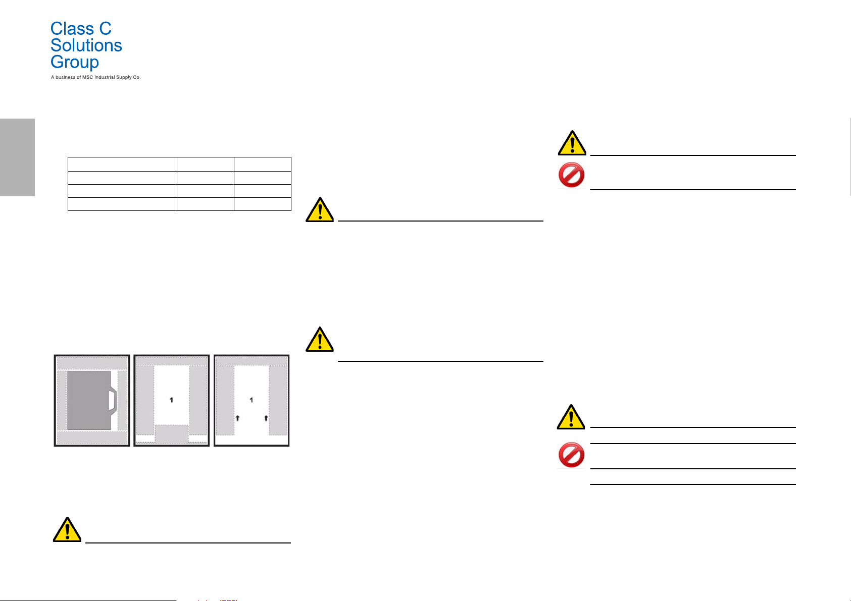
3.1.0 Packaging
Packaging includes a cardboard box with the following dimensions:
Dimensions Macchina Console
Width 460 mm 460 mm
Height 460 mm 200 mm
Depth (Length) 435 mm 435 mm
3.1.1 Opening the package
Remove the machine and the console from the packing materials following the instructions below:
Key-cutting machine
1. Remove the seals or the tape to open the package.
2. Open the box that contains the key duplicating machine.
3. Remove carton “6” that contains the case with the kit of
accessories.
4. Remove carton “5” from the box.
5. Remove carton “2” and “4” from the box.
6. Free the machine from the packaging material.
Console
1. Remove the seals or the tape to open the package.
2. Open the box that contains the console.
3. Free the console from the packaging material.
IMPORTANT!
We recommend you to keep the packaging during the
warranty period.
3.2.0 Transport
The markings on the packing materials indicate how to handle the
machine during transport.
3.2.1 Unloading and handling the machine
The machine can be unloaded manually by 2 or 3 persons, or by using
a handling equipment (for example a lift truck).
Avoid dropping the machine, even a small damage
could impair its correct functioning.
3.3.0 Temporary storing
If the installation of the machine does not occur immediately, store
the machine in a dry and properly ventilated place.
• Apply an appropriate coating .
• Rubber parts must be protected against too low
temperatures. Never store them outdoors, not even for
short periods.
If the machine is stored or remains unused for long periods or if it is started a long time after delivery, gaskets
or retaining rings may undergo hardening thus causing
leaks or seizures.
3.3.1 Characteristics of the place of installation
The key cutting machine must be placed on a smooth level bench
about 90 - 110 cm (35 - 43 Inches) high, suitable for bearing the weight
of the machine and keep it horizontal, thus avoiding vibrations and
stress.
Allow a 30 cm (12 Inches) clearance around and above the key cutting
machine for correct functioning and maintenance.
3.3.2 Temperature and humidity
The tool should be used in rooms with a temperature range of 0 and 40
°C (273 K - 313 K) and a relative humidity lower than 50 - 60%.
3.3.3 Working environment
The machine must be used in a place protected from bad weather
(rain, hail, snow etc.).
If the machine is used in places exposed to corrosion,
maintenance shall be scheduled in such a way as to
prevent extreme wear of the components.
Do not use the machine in explosive or partially explosive atmospheres or in the presence of inflammable
liquids of gases.
3.3.4 Lighting
In the place of installation lighting must be appropriate, in order to allow the correct use and maintenance of the machine.
3.4.0 Connections
3.4.1 Grounding
Key cutting machines BD LASER MAX have been designed in
compliance with the safety legislation in force and feature appropriate safety devices to prevent work accidents. In particular the
machine was built with materials that:
•are self-extinguishing;
• protect against electrocution.
The machine must be grounded through the centralized circuit of the
place of installation.
Warning:
Make sure that the main voltage is compatible with the
machine voltage.
Make sure that the active power outlets are grounded.
Do not touch the machine when your hands and/or feet
are wet or humid.
Avoid any contact with grounded plates.
6 BD LASER MAX Man. cod. B409652FG Class C Solutions Group
Page 9
START UP
A
B
C
4Start up
4.1.0 Notice for machine use
In order for the machine to function under optimum conditions and in
complete safety at all times:
• Keep the power cable away from sources of heat, humidity,
oil, water and sharp objects.
• Keep cutting tools sharpened and clean at all times to
ensure better and safer performance.
• Do not expose the machine to inclement weather.
• Disconnect the machines power cable before any
maintenance, repairs and whenever the machine is not
used for a lengthy period of time.
•Use only original spare parts.
4.1.1 Preliminary controls and setup
Before proceeding with the start up of the machine the operator must:
• Check to make sure the power cable is correctly connected
to the machine.
• Perform a general visual inspection of the machine to
ensure that no components have been removed or
modified.
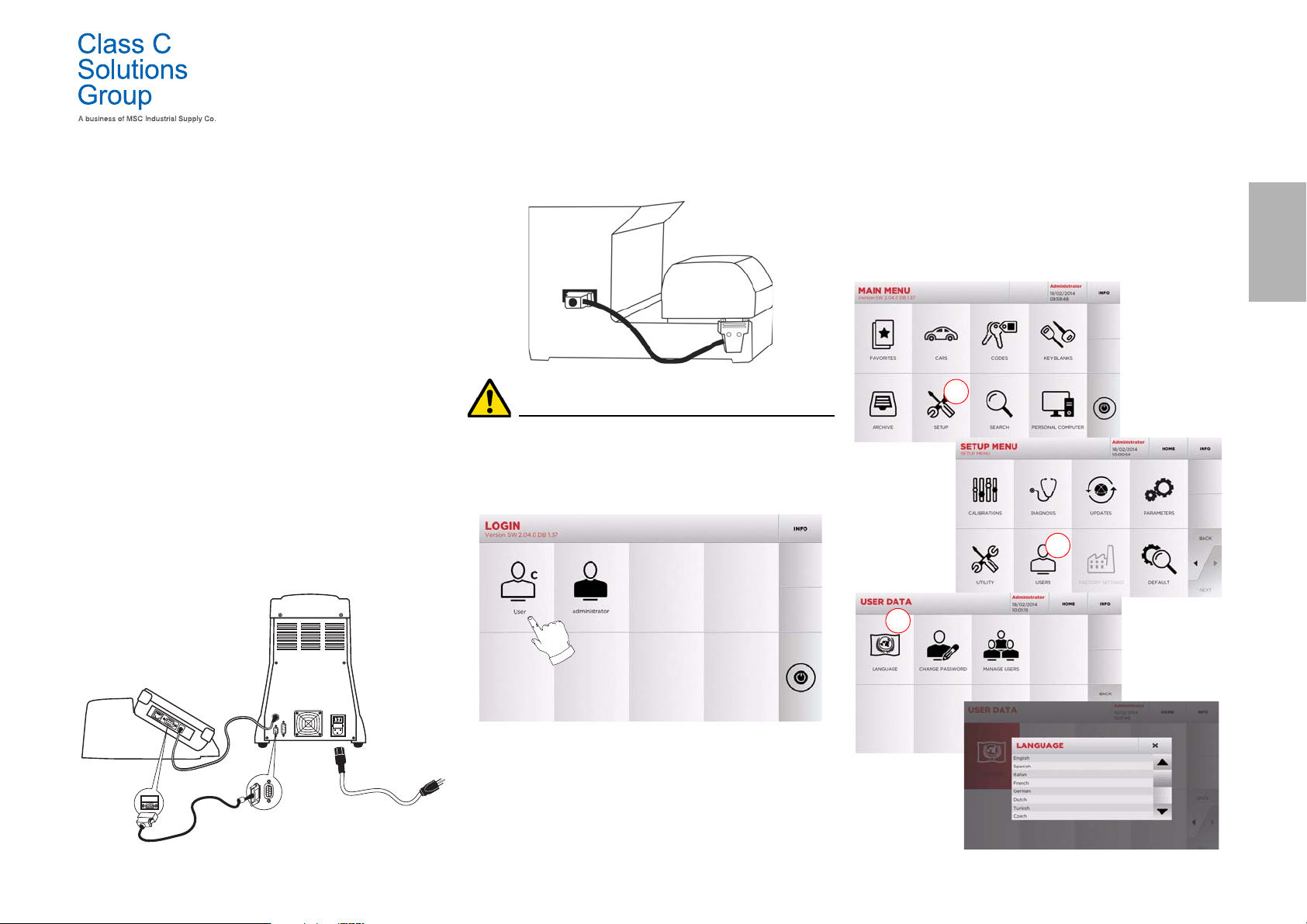
4.2.0 Starting the consolle
After checking that the emergency button has been pressed, connect the
consolle serial cable and the power cable to the duplicating machine.
Connect the cable when the machine is turned off.
Within a few minutes of switching on, the Touch-Screen will display
the “LOGIN” page.
• Select the user for operating with the machine (e.g. USER).
4.3.0 Language setting
How to proceed:
•From the MAIN MENU, select: “A”.
• From the SETUP MENU, select: “B”.
• Select “C” and chose the interested language.
ENGLISH
• With the admin user is possible to enter the Setup Menu for
managing calibrations and settings .
• In the following page enter the password to access the
MAIN MENU.
Note: No password is required for the first start of the
machine.
Class C Solutions Group BD LASER MAX Man. cod. B409652FG 7
Page 10
SETUP
131 2
5 76
14
8
9
A
ENGLISH
5Setup
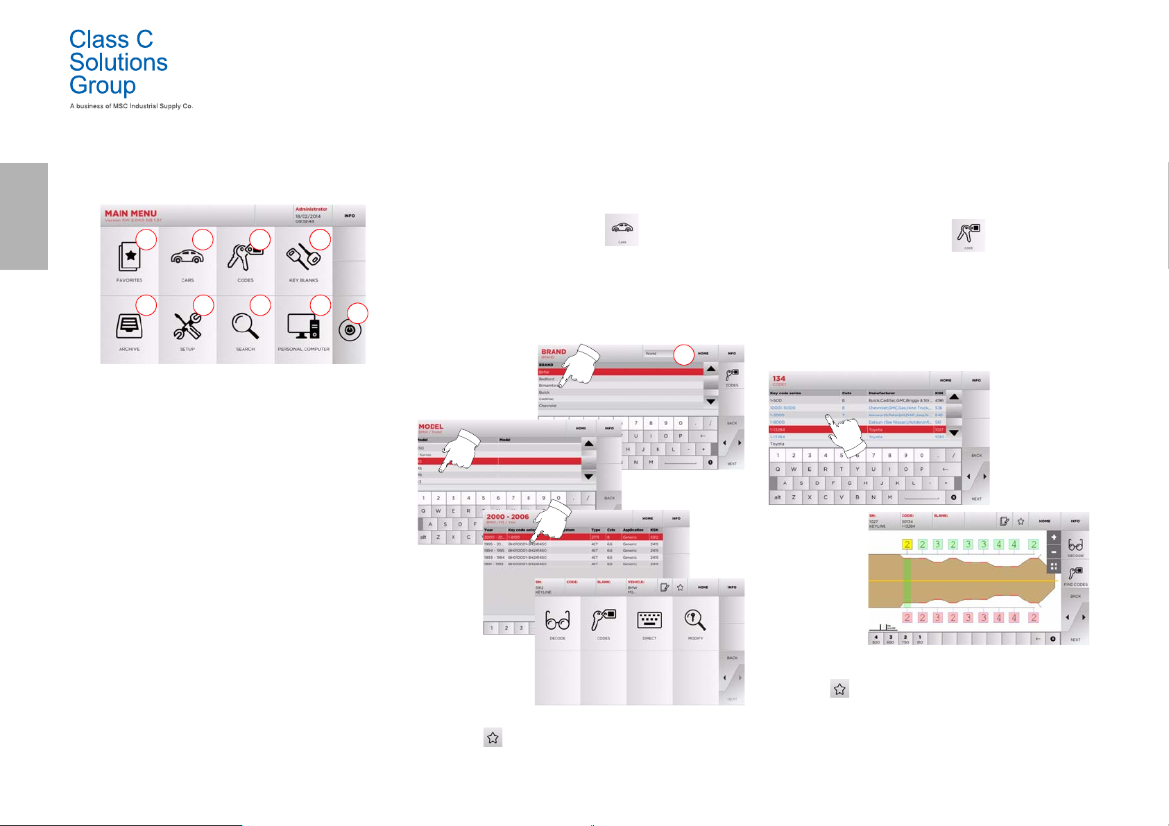
5.1.0 Main Menu
Options displayed:
1. This function gives access to a collection of "Bookmarks"
previously saved by the user, for faster access to the
most frequently saved keys/systems.
2. This allows you to search and select data via the car
brand and model.
3. This allows you to search and select data via the original
indirect code (profile and series).
4. This allows you to search and select data via the Class C
Solutions Group key article and similar blank keys made
by other manufacturers.
5. This function makes it possible to access the archive
containing the keys identified during the search and
decoding processes, so that they can be retrieved quickly
every time the user needs them.
6. To access the menu for adjusting the cutting and
decoding process, updating and diagnostics of the
machine and calibrating the operating parameters.
7. This function allows access to the database on the
machine to search for coded processing data or
deciphering.
8. Set of functions used to connect the machine to
programmes being executed on remote PCs and import
DAT files.
9. Back to login page.
8 BD LASER MAX Man. cod. B409652FG Class C Solutions Group
5.1.1 Search by car brand
The “CAR” menu makes it possible to search and duplicate a key
through a list of car brands included in the database.
How to proceed:
• From the MAIN MENU, select “ ”.
• Select one of the options in the top drop-down menu (A).
• Input the brand or scroll the menu and select the desired
brand (e.g., BMW), then press “
• Choose the car model first, then the year of production, and
press “
• From the operating menu, choose one of the search or key
Note: From now on, please refer to chapter 7 on page15.
Note: The “ ” symbol makes it possible to save the selected
►”.
modification options: DECODE, CODE, DIRECT and MODIFY.
key in the list of bookmarks. See paragraph6.2.0.
►”.
5.1.2 Search by code
The search by code is made when one wishes to search for a key using
the indirect code pertaining to the key's series, as provided by the manufacturer.
How to proceed:
•From the MAIN MENU, select “ ”.
•Input the complete original code (or part of the same)
through the keypad and scroll the list of articles to choose
the desired one.
Note: All the series and the records that may contain the
inserted code are displayed in ascending order, with
attached application / brand of use.
•Press “
Note: From now on, please refer to chapter 7 on page15.
Note: The “ ” symbol makes it possible to save the selected
• To go back to the previous page, press the “
►” to access the key modify menu.
key in the list of bookmarks. See paragraph6.2.0.
◄” key.
Page 11
SETUP
A
B
131 2 4
5
6 7
1
2
3
4
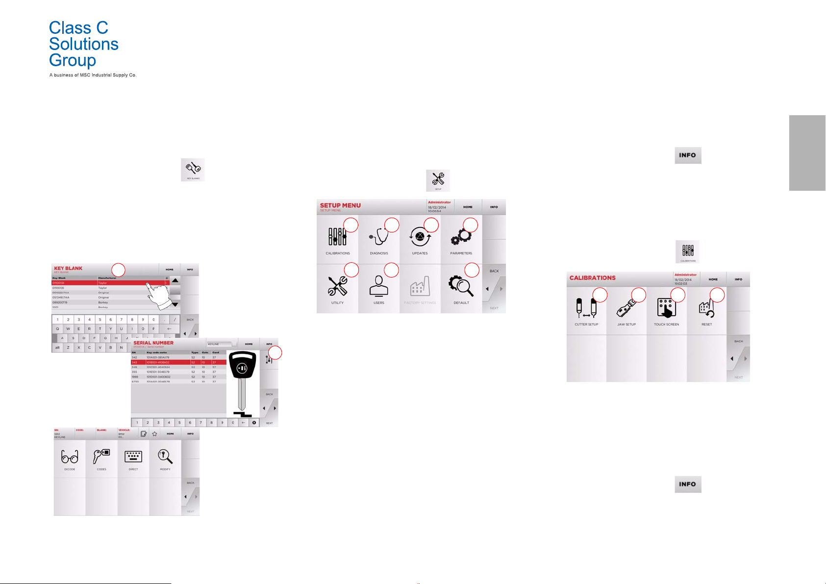
5.1.3 Search by article
Selecting the search by article function allows quick access to the information that refers to a Class C Solutions Group key article or to
other well known brands.
How to proceed:
•From the MAIN MENU, select:
• Select one of the options in the top drop-down menu (A).
• Input the article code for the Class C Solutions Group key
or other key, then press “
• Choose the desired code, or press the “B” button to select
the manufacturer of the blank key (e.g. Keyline) then enter
it with
• From the operating menu, choose one of the search or key
Note: From now on, please refer to chapter 7 on page15.
Class C Solutions Group BD LASER MAX Man. cod. B409652FG 9
“►”.
modification options: DECODE, CODE, DIRECT and MODIFY.
►”.
5.2.0 Setup Menu
The main menu allows access to the set-up menu to regulate the cutting and reading devices, to update the machine and use the diagnostic function.
How to access the page:
• From the MAIN MENU, select:
Options displayed:
1. For the calibration of the devices on the machine.
2. To access the status check menus of the main devices of
the machine.
3. To access the software and database updating procedure
of the machine.
4. To consult and set the operating parameters of the
machine.
5. To access the following functions:
•Network Status: displays the status of the connection.
• Keys History: to access the database of duplicated keys.
• Cutter change: guided procedure for cutter change.
• Tracer point change: guided procedure for tracer point change.
• Statistics: keeps track of the total number of cut keys
and of other useful counters.
• Format USB drive: to format the USB drive.
• Date and Time: to set current date and time.
• Restart: restarts the program automatically.
• Reboot: restarts the whole system automatically.
• Machine data: displays some useful pieces of information,
such as the machine serial number or the software version.
6. To access the user data management menu described in
paragraph8.1.0 on page17.
7. To access all predefined settings for some viewing
parameters, such as the unit of measure, the preferred
vehicle brand, the preset region and numbering system.
• For further information select “ ” from the display .
5.3.0 Calibrations Menu
Through the CALIBRATIONS menu it is possible to access the calibration functions of the machine's devices, in order to obtain the correct
execution of the duplication process.
How to access the page:
•From the SETUP MENU, select:
Options displayed:
1. Used to calibrate the cutter manualy and to adjust its
position in respect to the X and Y axes.
2. To select the jaw to be installed and to calibrate it
according to the type of key to be cut.
3. To regu late the Touc h Scree n setti ngs.
4. To access the menu that allows the operator to reset the
tracer point and jaws.
• For further information select “ ” from the display .
ENGLISH
Page 12
SETUP
2
1
1
2
131 2
ENGLISH
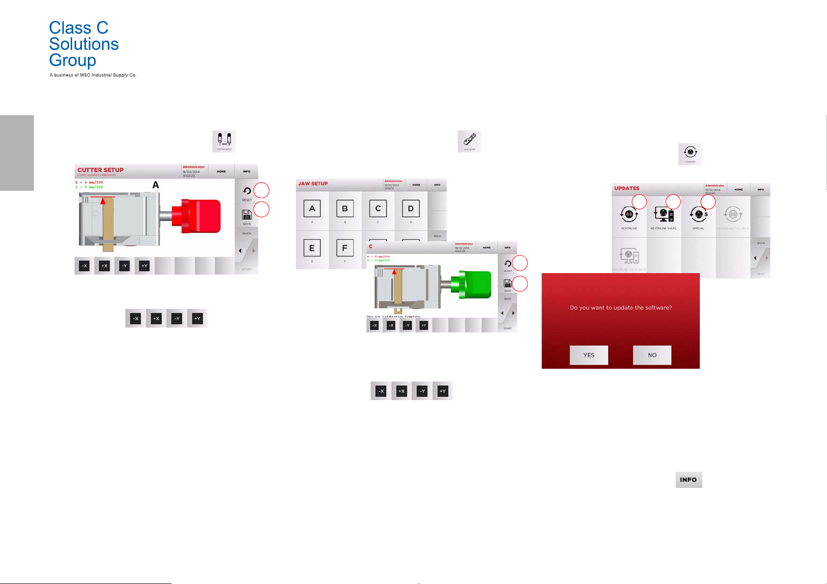
5.3.1 Cutter Setup
How to proceed:
•From the CALIBRATIONS MENU, select:
• Change the position of the X-Y axes with the buttons:
• On the top left of the display it is possible to view the
height to be modified.
• Save your changes by pressing “1”.
Note: If you leave the page without pressing the "1" key , all
changes shall be lost.
• To reset the changes and go back to the previous setting,
press “2”.
5.3.2 Jaw Setup
How to proceed:
•From the CALIBRATIONS MENU, select:
• Install the required jaw and select the corresponding code
from the JAW SETUP MENU.
• Insert the calibration template as requested.
• Then press “1” to launch the jaw self-calibration process.
• Change the position of the X-Y axes with the buttons:
• On the top left of the display it is possible to view the
height to be modified.
• Save your changes by pressing “1”.
Note: If you leave the page without pressing the "1" key , all
changes shall be lost.
5.4.0 Update
It is possible to update the machine through the graphic interface.
How to access the page:
•From the SETUP MENU, select:
Options displayed:
1. To proceed with the online software and database
update, through the "Keyonline" service.
2. The update package is downloaded through a normal PC
connected to the internet and saved on a USB flash drive,
so as to be able to install it later on in the machine.
3. To proceed with the software and database update,
taking the data from a USB flash drive.
• To reset the changes and go back to the previous setting,
press “2”.
10 BD LASER MAX Man. cod. B409652FG Class C Solutions Group
•Press “
►” and follow the instructions on screen to
calibrate the jaw correctly.
• For further information select “ ” from the display.
Page 13
SETUP
5.4.1 Keyonline Update
Note: Before updating, check that the console is connected to
a LAN Network.
Pressing the "KEYONLINE" key, the programme proceeds to send the
necessary information to the Keyonline service and later to download
the update package.
According to the quantity of the data to be downloaded,
the process might require a waiting time.
Note: During this phase, some error messages might appear,
stating that the machine is not registered or that it is
impossible to download the updates. In such cases,
please check that all the preliminary operations have
been concluded and that all the network parameters are
configured correctly. For further help, please contact the
Class C Solutions Group Service Centre.
How to proceed:
• From the UPDATES menu select:
• Disconnect any USB flash drives connected to the machine
and press the "YES" key.
• The programme shall reboot and the update software
executed; the user might be required to turn off and reboot
the machine.
• Follow the instructions and wait until the end of the
procedure, whereupon the most recent versions of the
software and database shall be available.
• To annul the operation, press NO.
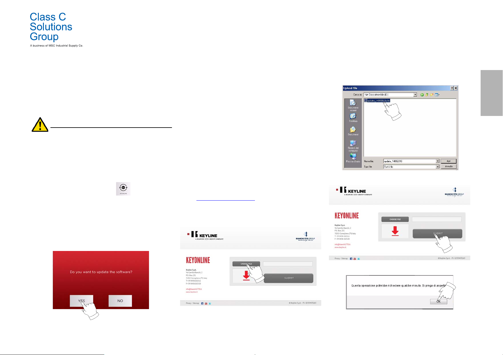
5.4.2 Keyonline via PC Update
If it is not possible to configure the machine to connect to the internet,
this procedure makes it possible to update it by connecting to
Keyonline through a PC with internet connection.
How to proceed:
• Press the "VIA PC" button; a message asking to connect a
USB flash drive to the machine shall appear.
• Then, press the "NEXT" button to proceed, or the
"CANCEL" one to cancel the operation.
• The programme shall copy a file with a .csk extension on
the USB flash drive, containing the information to be sent
to Keyonline to update the machine.
• After a few seconds a message stating that the operation
is finished shall appear and the user will be asked to
download the update from Keyonline.
• Interrupt the operation by pressing "CANCEL" or proceed
with the following instructions:
1. disconnect the USB flash drive and connect it to a PC
with an internet connection.
2. Using the browser, connect to the following web page:
http://keyonline.keyline.it/
3. Select the "CHOOSE FILE" button to access the file
selection dialogue box.
4. Search and select the .csk file previously saved in the flash drive,
then press "OPEN".
ENGLISH
5. Press the "SUBMIT" button.
6. The following message shall appear:
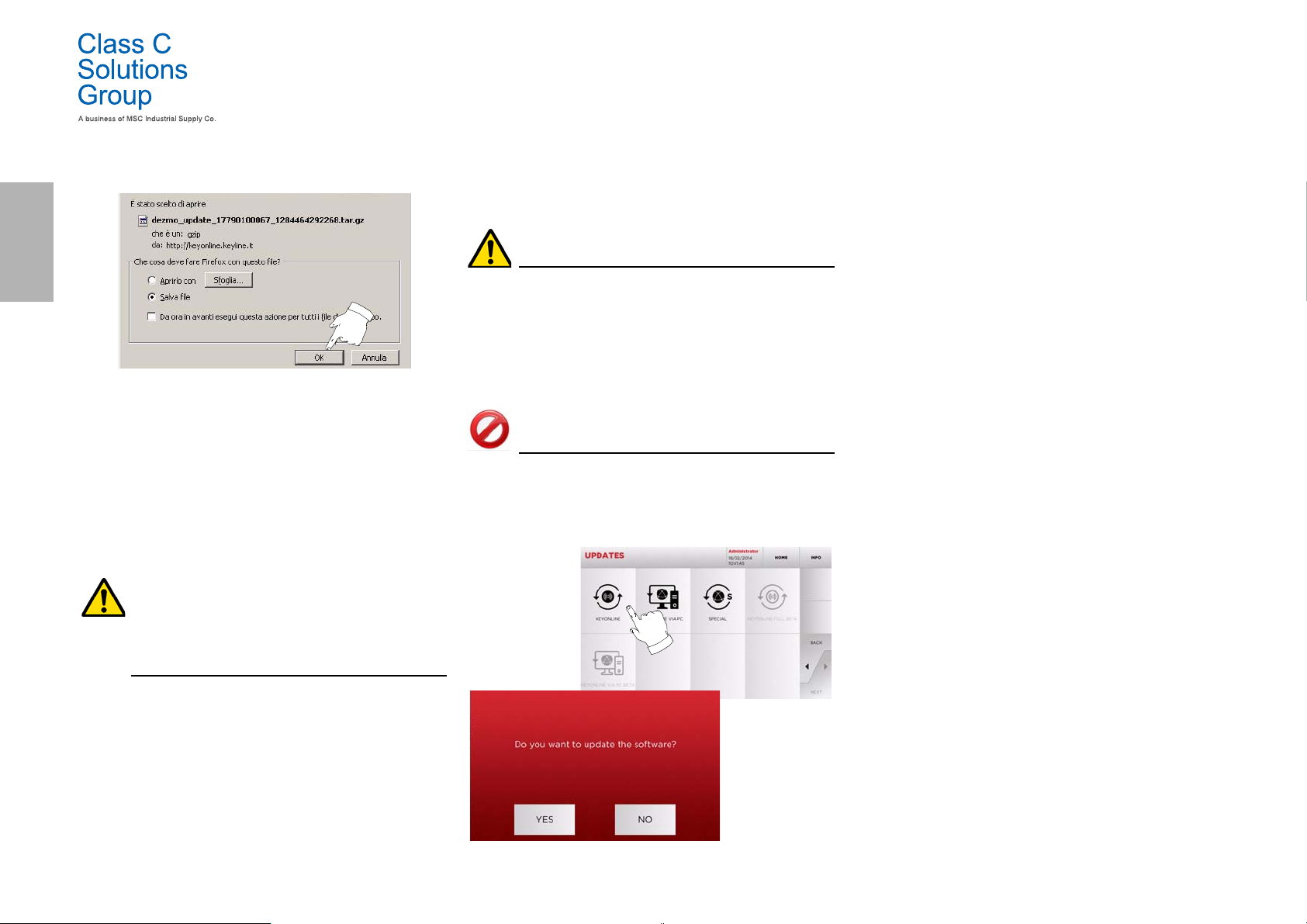
7. Press "OK" to start downloading the file and when the
browser asks where to save it, choose the USB flash drive.
Class C Solutions Group BD LASER MAX Man. cod. B409652FG 11
Page 14
ENGLISH
Note: The download may require some minutes, it is necessary
to wait for the process to end.
8. At the end, remove the flash drive and connect it again to
the machine.
SETUP
5.4.3 Special
Warning:
This update procedure may be carried out only upon request by Class C Solutions Group.
How to proceed:
• Pressing the USB button, the programme will ask you to
insert a USB flash drive containing the data for the update.
Note: The data for this kind of update can be provided
EXCLUSIVELY by Class C Solutions Group.
It is not possible to update the machine with packages
downloaded from "Keyonline" of from the Class C
Solutions Group server.
Note: The downloaded package can be used only by the
machine with which the update procedure was started.
9. After connecting the USB flash drive to the machine, press
NEXT. The updates shall be analysed and loaded in the
machine's memory.
During this phase, messages may appear stating the
presence of errors in the package, the absence or invalidity of the licence. In these cases, check that you have
used the same USB flash drive that you connected to the
machine at the beginning of the update process. Contact
the Class C Solutions Group Service Centre to solve any
problems.
10. At the end of the download a message confirms that the
data have been received and can now be installed.
11. Disconnect the USB flash drive connected to the machine
and press the "INSTALL" button. To annul the operation,
press CANCEL.
12. The programme shall reboot and the update software
executed; the user might be required to turn off and
reboot the machine.
13. Follow the instructions and wait until the end of the
procedure, whereupon the most recent versions of the
software and database shall be available.
12 BD LASER MAX Man. cod. B409652FG Class C Solutions Group
• After inserting the flash drive, press YES to update the
machine.
• To annul the operation, press NO.
• Follow the instructions to the end of the procedure.
Page 15
KEY SEARCH
131 2 4
175 6
A
A
6Key search
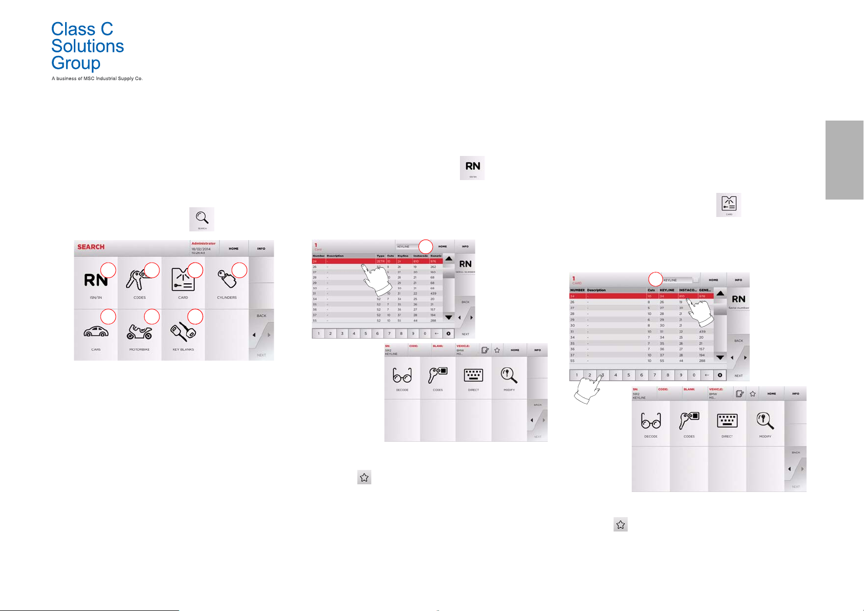
6.1.0 Search menu
This function is used when some details of the key to be duplicated are known, such as the manufacturer of the rough piece, the
cylinder, the car or motorcycle brand, the indirect code or the
card number. Once the machine's database has been se arched, it
is possible to input the key code manually, or obtain it through
the decoding process.
How to access the page:
•From the MAIN MENU, select:
Options displayed:
1. This allows you to search and quickly select data via the
RECORD number attributed by Class C Solutions Group to
a specific series, key and card.
2. This allows you to search and select data via the original
code (profile and series).
3. This allows you to search and quickly select data through
the card number, according to the Class C Solutions
Group and other manufacturers numbering system.
4. This allows you to search and select data via the lock
and/or cylinder manufacturer’s brand.
5. This allows you to search and select data via the car
brand, model and year of manufacture.
6. This allows you to search and select data via the
motorcycle brand, model and year of manufacture.
7. This allows you to search and select data via the Class C
Solutions Group key article and similar blank keys made
by other manufacturers.
Class C Solutions Group BD LASER MAX Man. cod. B409652FG 13
6.1.1 Search by record number
The “RECORD NUMBER” page makes it possible to search for the type
of key to be duplicated by inputting the key's system number.
How to proceed:
•From the "SEARCH" page, select “ ”.
• Select one of the options in the top drop-down menu (A).
• Input the Record number for the make / model / year / series
/ profile to be duplicated, then press “
• From the operating menu, choose one of the search or key
modification options: DECODE, CODE, DIRECT and MODIFY.
Note: From now on, please refer to chapter 7 on page15.
Note: The “ ” symbol makes it possible to save the selected
key in the list of bookmarks. See paragraph6.2.0.
• To go back to the previous page, press the “
►”.
◄” key.
6.1.2 Search by code
Note: This procedure is described in paragraph5.1.2 on page8
6.1.3 Search by card
This function makes it possible to obtain quick access to a specific lock
system, by choosing the memorised key manufacturer's card.
How to proceed:
• From the "SEARCH" page, select “ ” button.
• Select one of the options in the top drop-down menu (A).
• Input the Record number for the make / model / year / series /
profile to be duplicated, then press “
• From the operating menu, choose one of the search or key
modification options: DECODE, CODE, DIRECT and MODIFY.
Note: From now on, please refer to chapter 7 on page15.
Note: The “ ” symbol makes it possible to save the selected
key in the list of bookmarks. See paragraph6.2.0.
• To go back to the previous page, press the “
►”.
◄” key.
ENGLISH
Page 16

KEY SEARCH
A
A
ENGLISH
6.1.4 Search by cylinder brand
This function is used when you know the bitting code of the key to be
copied or if you wish to search for it using the decoding process. The
menu makes it possible to search through the system’s database as
described below.
How to proceed:
•From the "SEARCH" page, select: .
• Select one of the options in the top drop-down menu (A).
• Scroll the menu of available brands or enter the name and
choose the required one (e.g.: ACURA).
•Press “
• From the operating menu, choose one of the search or key
►” to go to the list of blank keys and choose the
one most appropriate for the selected brand (e.g. 342),
then press “
modification options: DECODE, CODE, DIRECT and MODIFY.
►”.
6.1.5 Search by motorbike brand
The “MOTORBIKE” menu makes it possible to search and duplicate a
key through a list of brands included in the database.
How to proceed:
•From the "SEARCH" page, select:
• Select one of the options in the top drop-down menu (A).
• Enter the brand or scroll the menu and select the required
one (e.g.: DUCATI), then press “
• Choose the car model first, then the year of production, and
press “
• From the operating menu, choose one of the search or key
►”.
modification options: DECODE, CODE, DIRECT and MODIFY.
►”.
6.1.6 Search by car brand
Note: This procedure is described in paragraph5.1.1 on page8.
6.1.7 Search by article
Note: This procedure is described in paragraph5.1.3 on page9
6.2.0 Bookmarks list
Every time a key is modified, irrespective of which database it comes
from, it is possible to save the changes in a specific "favourite keys"
database.
How to proceed:
• Press the button from “MODIFY” page after making
the necessary changes.
• Input the name for the subsequent searches, then press
“OK”.
• Confirm that you want to save by pressing "YES" and go
back to the "MODIFY" page.
The black icon shows that the key has been saved in the “FAVORITES” database.
Later, the user shall be able to look for the key by accessing the “FAVORITES” menu from the main menu:
Note: This function must not be confused with the saving of a
key in the archive. The saving concerns all the
information that characterise a key (bitting, cutting
parameters, material, number of copies, etc.) for both
keys found in a database (coded) and read keys. This list,
Note: From now on, please refer to chapter 7 on page15.
• To go back to the previous page, press the “
14 BD LASER MAX Man. cod. B409652FG Class C Solutions Group
◄” key.
Note: From now on, please refer to chapter 7 on page15.
instead, leads directly to a RN, that is to say, a technical
card for cutting a key (and so the bitting and other data
are not memorised).
Page 17
MODIFY AND CUT
7Modify and cut
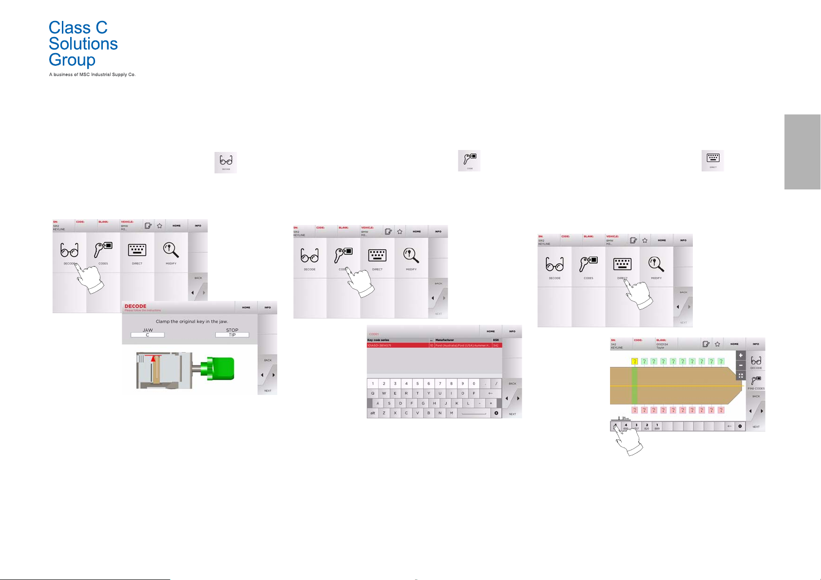
7.1 . 0 D e c o d e
This function makes it possible to decode the key using the selected
key system.
How to proceed:
• From the key search sub-menu, select “ ”.
• Insert the original key in the jaws and lock it in place.
• Then follow the instructions on screen until the end of the
decoding process.
7. 2 . 0 C o d e
This function makes it possible to search for a specific code
contained in the data base and obtain the relevant coding.
How to proceed:
• From the key search sub-menu, select “ ”.
• Input the blind code.
•Then press
“CUTTING” one (for additional information, please refer to
paragraph7.5.0 on page16).
►” to go to the following screen, the key
7. 3 . 0 D i r e c t
This function makes it possible to insert the bitting code for the key
directly.
How to proceed:
• From the key search sub-menu, select “ ”.
• Input a value for each cut that shall correspond to the
bitting code.
•Then press
“CUTTING” one (for additional information, please refer to
paragraph7.5.0 on page16).
►” to go to the following screen, the key
ENGLISH
Class C Solutions Group BD LASER MAX Man. cod. B409652FG 15
Page 18
MODIFY AND CUT
3 4 5 6 7 8 9 10
1
2
3
1
2
4 5 6 7 8
ENGLISH
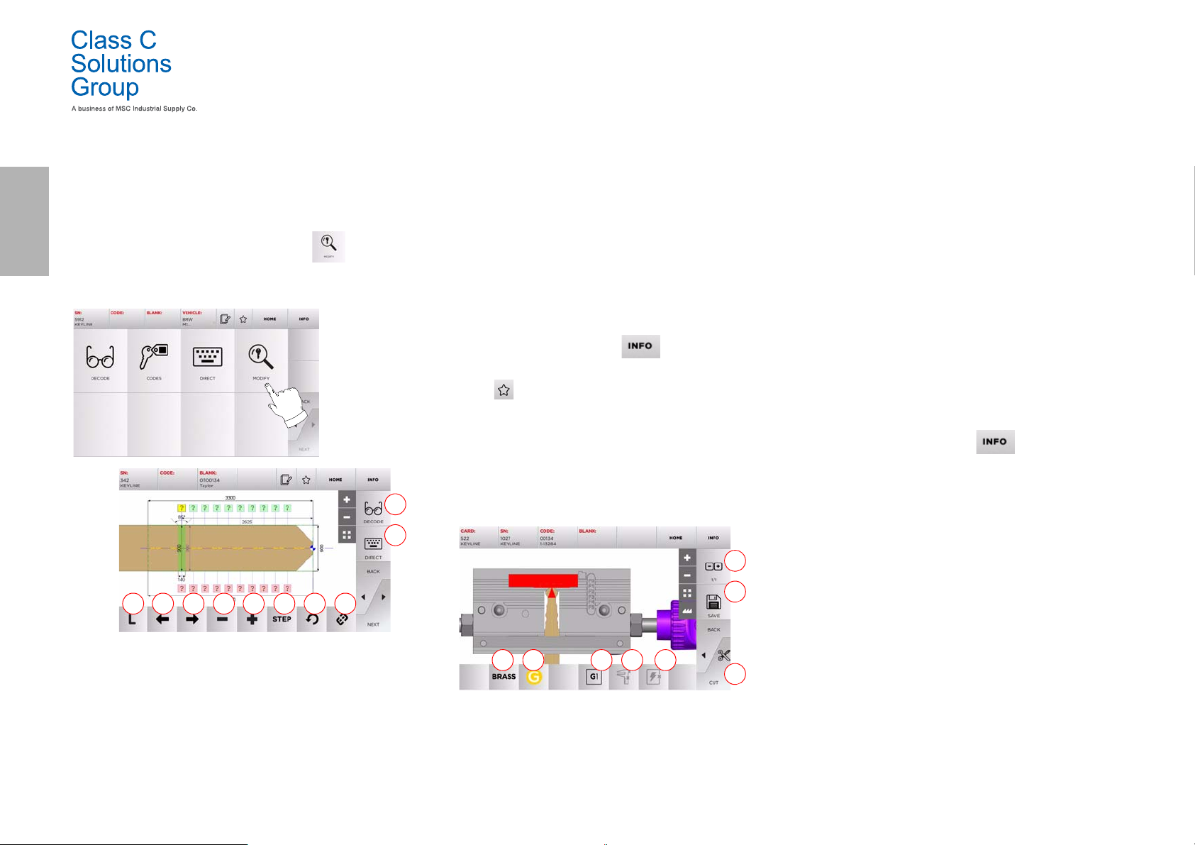
7.4.0 Modify menu
The MODIFY MENU is used to modify the cut parameters for a key and
it also makes it possible to personalise some characteristics of the
key, according to the client's specific requirements.
How to proceed:
• From the key search sub-menu, select “ ”.
• This displays the technical sheet for the selected article and
makes it possible to change some of the key characteristics.
5. With the right arrow button is possible to scroll the
spaces moving to right direction.
6. With the minus button is possible to decrement the depth
of the highlithed tooth.
7. With the plus button is possible to increment the depth of
the highlithed tooth.
8. This makes it possible to select the depth increase or
decrease rate when the + or - buttons are pressed. The
available options are: one STEP is either 0.1 mm or 0.01 mm.
9. With this button is possible to reset the modifications
made on the selected tooth.
10. With this button is possible to modify simultaneously all
the teeth.
• For further information select “ ” from the display .
Note: The “ ” symbol makes it possible to save the selected
key in the list of bookmarks. See paragraph6.2.0.
7. 5.0 Ke y cu t m e nu
Once the key to be copied has been searched using the relevant functions in the Database menu, the programme will direct the user to the
CUT screen, that makes it possible to duplicate the desired key.
3. Starts the key cutting process.
4. With this button is possible to change the default
material. The selectable material are: BRASS,
ALUMINUM, STEEL, NIKEL SILVER, CUSTOM. Each
material has a dedicated set of parameters for the
movement speed and cutter speed for optimizing the
quality of the cut and ensure the life of the cutter. The
custom material can be customized on the Parameters
Panel of the Setup Menu.
5. With this button is possible to select the Jaw that has to
be used to cut the key, only compatible Jaws will be
selectable.
6. Displays the type of stop to be used to cut the key.
7. With this button is possible to enable or disable the
measure of the dimension of the key.
8. With this button is possible to enable or disable the
measure of the width of the key, this measure is faster
respect of the complete measure and is useful to
optimize the cut procedure but when using blank keys
with precuts the complete measure is preferred .
• For further information select “ ” from the display .
Options displayed:
1. With this button is possible to decode the key using the
selected key system.
2. With this button is possible to insert the cuts directly.
3. With the Cut Type button is possible to select between
the possible cut types for the selected key. For Flat keys
cut types are: Normal, Laser and Plane.
4. With the left arrow button is possible to scroll the spaces
moving to left direction.
16 BD LASER MAX Man. cod. B409652FG Class C Solutions Group
Options displayed:
1. With this button is possible to set the amount of copies
that need to be cut.
2. With this button is possible to save the key.
Page 19
ARCHIVE, PC AND USER MENU
1 2 312
1 2 3
8Archive, PC and user menu
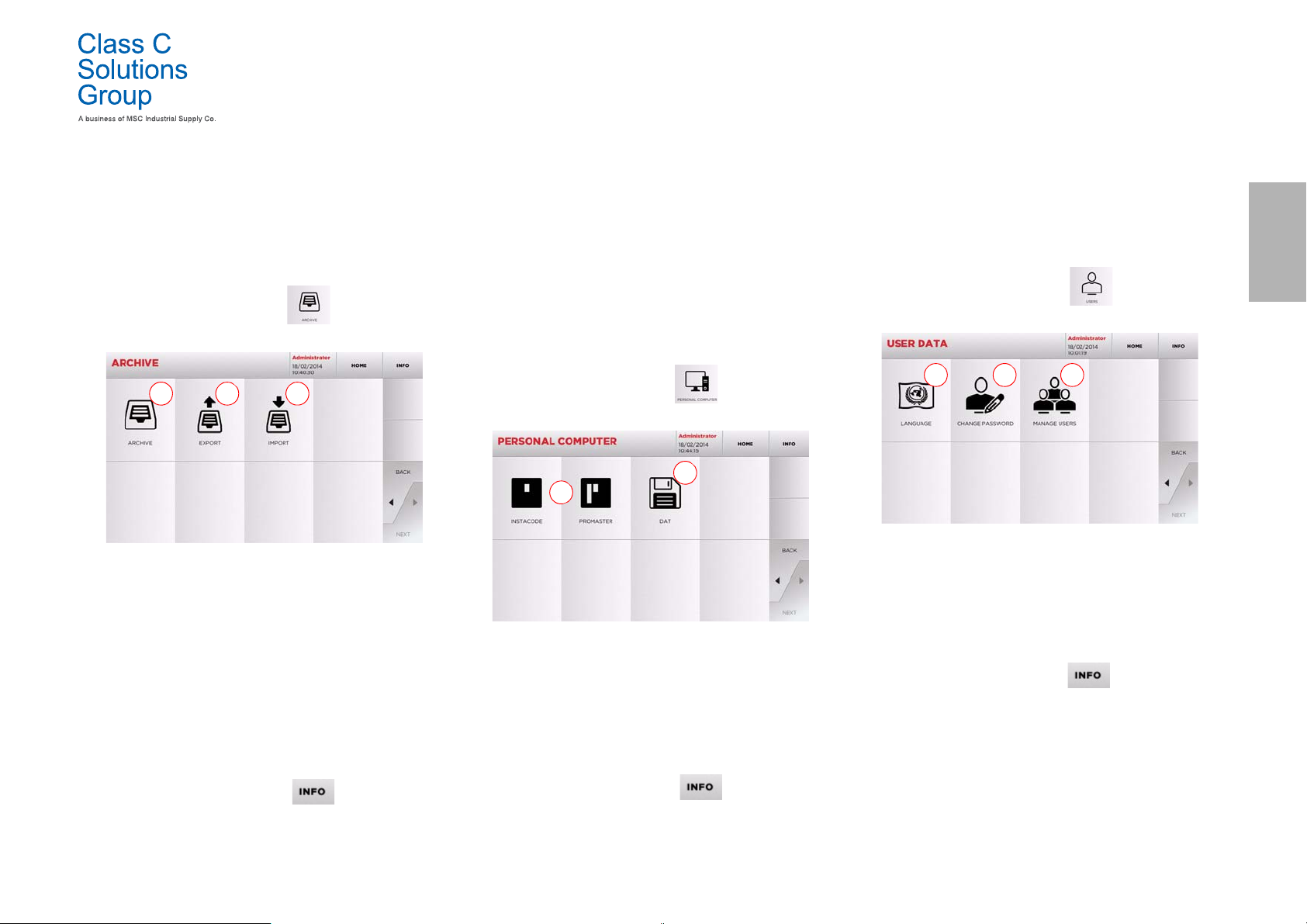
8.1.0 Archive Menu
The ARCHIVE menu makes it possible to manage the user data and
the database saved by the user during the key reading, decoding and
modification phases. It is also possible to access the import and
export functions from and to external supports (USB flash drive).
How to access the page:
•From the MAIN MENU, select:
Options displayed:
1. This function makes it possible to access the archive
containing the keys identified during the search and
decoding processes, so that they can be retrieved quickly
every time the user needs them.
2. This function makes it possible to export a file from the
machine's database to a USB flash drive. The export and
import functions allow the customer to exchange
customised data between machines or create backup
copies of the exported archive.
3. This function makes it possible to import a file from a USB
flash drive to the machine's database. Data imported from
the USB flash drive shall be saved in the archive.
• For further information select “ ” from the display .
.
8.2.0 Personal Computer Menu
Through this menu it is possible to access the functions to interface
BD LASER MAX with queuing software that might reside in a remote
PC or USB flash drive.
It is possible to import job queues containing several processes
(JOBS).The JOBS, in turn, contain information for each key to be cut,
such as: type of key, type of bitting, and number of copies to be cut.
The programme makes it possible to select and execute only one JOB
at a time, until the queue is exhausted.
How to access the page:
• From the MAIN MENU, select:
Options displayed:
1. These menus manage and process job queues created
with Instacode and Promaster key processing software
and sent to the machine.
2. This menu makes it possible to import, manage and
process job queues saved in DAT format files.
• For further information select “ ” from the display.
.
8.3.0 User Menu
The USER menu makes it possible to manage the user data and the
database saved by the user during the key reading, decoding and modification phases.
How to access the page:
•From the SETUP MENU, select:
Options displayed:
1. This allows you to change displayed language (refer to
paragraph4.3.0 on page7).
2. Thisallows you to change password to existing users.
3. This allows you to manage users, add a new user, remove
exixting users and change information.
• For further information select “ ” from the display.
ENGLISH
Class C Solutions Group BD LASER MAX Man. cod. B409652FG 17
Page 20
ENGLISH
Bar ‘tooth’ to
Patent pending
Triangular mark
replace the cutter
T- Handle hexagon wrench (long) 3mm
Cutter calibration cut out
9Maintenance, Dismantling and disposal
Warning: IMPORTANT!
Before carrying out any maintenance operation you
must turn OFF the power and disconnect the power cord.
Maintenance must be carried out only by qualified personnel equipped with appropriate protective devices
for safe work.
Always use original Class C Solutions Group spare parts.
9.1.0 General information
MAINTENANCE, DISMANTLING AND DISPOSAL
Poor ventilation could cause a machine overheating
and damage the components.
9.2.2 Cleaning the working area
At the end of each working day clean the machine removing scrap and
burrs to ensure proper functioning of the machine and to prevent any
damage to its parts.
Empty the shaving collection drawer every time that the work surface
is cleaned or whenever it is full of shavings.
9.1.1 Skills of maintenance personnel
The machine operator must be knowledgeable about machine operation.
9.1.2 Type of Maintenance
Ordinary Maintenance
• Servicing operations that must be carried out periodically
by the machine operator.
• The purpose of ordinary maintenance is guarantee regular
functioning of the machine and a consistent quality of the
product.
• The maintenance schedule may vary in relation to work or
environmental conditions in the place of installation.
Complex Maintenance
• Complex maintenance consists of actions to be taken only
when given conditions occur (break downs, failures,
replacement of parts).
• Due to the complex nature of such actions and the special
tools required, we recommend you should contact
qualified personnel from or authorized by Class C
Solutions Group.
9.2.0 Ordinary maintenance
We recommend inspecting the machine periodically and replace worn
parts.
9.2.1 Checking and cleaning the fan
It is suggested to periodically check the cleaning level of the air grids
and make sure that there is no accumulated dust that could obstruct
the air passage.
Do not clean the machine with compressed air.
9.2.3 Cleaning the display
To clean the Touch Screen display we recommend using a micro-fibre
cloth; avoid using substances that contain alcohol or solvents.
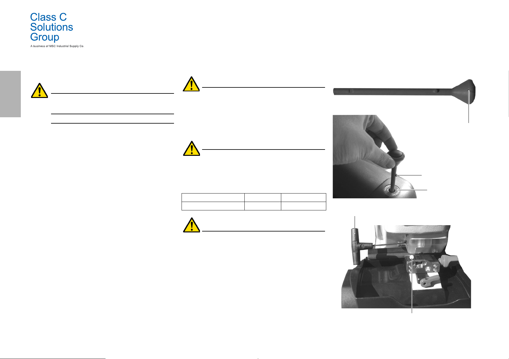
9.2.4 Replacing the milling cutter
Spare part description Code Frequency
Milling cutter 2,5mm RIC03304B When required
Before carrying out this operation disconnect the
power cable from the mains.
Required tools when replacing the fuses
•Patent pending.
• 1 T- Handle hexagon wrench (long) 3mm.
How to proceed:
• insert the bar to remove the cutter into the “Patent
pending” seat;
• rotate the bar slowly until the bar ‘tooth’ fits into the slot
located inside the “Patent pending” seat;
• rotate the bar: the triangular mark on top of the bar will
point to the left;
• insert the T-shaped 3 mm hexagon wrench in the hole to
unlock the cutter (see picture in the next screen);
• loosen the nut that fastens the cutter;
• pull out the bar from the “patent pending” seat and remove
the cutter.
18 BD LASER MAX Man. cod. B409652FG Class C Solutions Group
Page 21
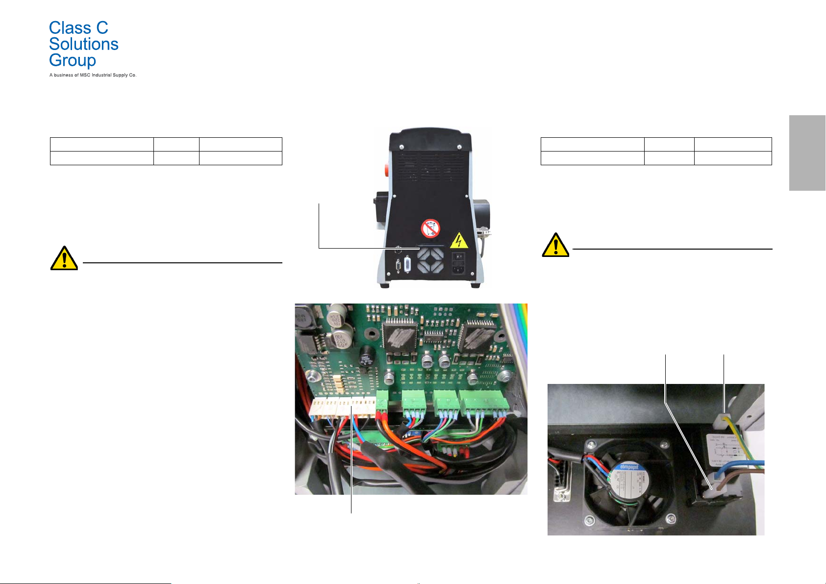
MAINTENANCE, DISMANTLING AND DISPOSAL
Fan
connection
Screws to fasten
the fan
Cable B Cable A
9.2.5 Replacing the fan
Spare part description Code Frequency
Fan RIC04268B When required
Required tools
Safety warning
How to proceed:
• 2mm hexagon wrench.
• 2,5mm hexagon wrench.
Before carrying out this operation disconnect the
power cable from the mains.
• remove the back cover and the protection grid of the card;
• remove the straps;
• disconnect the fan cable;
• use a 2 mm wrench to loosen and remove the 4 screws that
fasten the fan to the back cover;
• insert a new fan and connect the cable;
• fix the cables with new straps;
• fasten the fan with the 4 screws;
• close the rear carter and the protection grid of the card and
fix them.
9.2.6 Replacing the startup unit
Spare part description Code Frequency
Spina C/Portafusibile RIC02988B When required
Required tools
•2mm hexagon wrench.
• 2,5mm hexagon wrench.
Safety warning
Before carrying out this operation disconnect the
power cable from the mains.
How to proceed:
• remove the back cover;
• disconnect cables “A” and “B” from the startup unit;
• extract the unit from its seat and insert a new one;
• connect the cables again;
• put the back cover back into place and tighten the
fastening screws.
ENGLISH
Class C Solutions Group BD LASER MAX Man. cod. B409652FG 19
Page 22
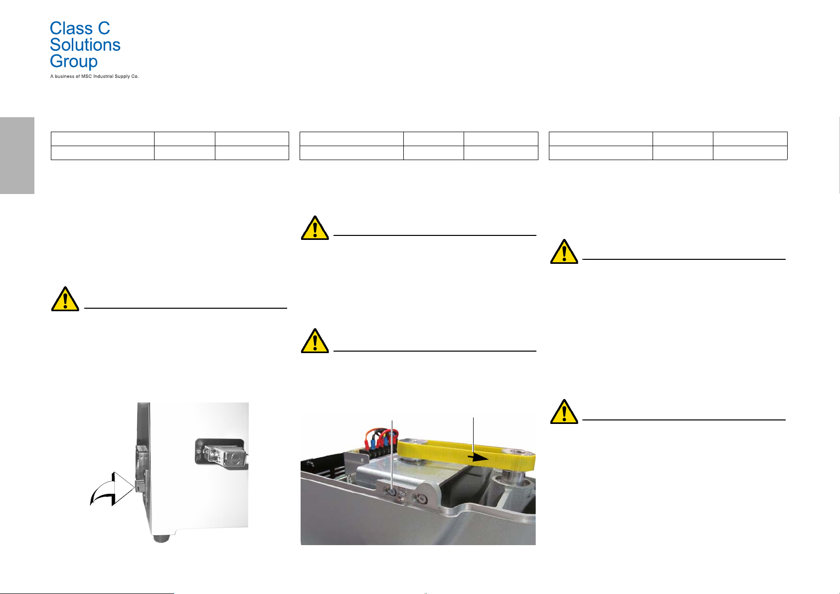
MAINTENANCE, DISMANTLING AND DISPOSAL
Fastening screws
Arrow indicating direction
ENGLISH
9.2.7 Inspecting and replacing the fuses
Spare part description Code Frequency
Rapid fuse 4A 5x20 RIC02592B When required
The BD LASER MAX key duplicating machine is equipped with 2 fuses
located in the power unit next to the switch, which have the purpose
to protect the machine from surges and short circuit.
If the machine fails to start after you have turned on the main switch,
we recommend you inspect the fuses in the power unit and replace
them if needed.
Required tools when replacing the fuses
• Tester, ohm meter, multimeter etc (to measure fuses’
continuity).
•Screwdriver.
Before carrying out this operation disconnect the
power cable from the mains.
How to proceed:
• press slightly on the tongues of the fuse carrier to pull it
out from its seat;
•inspect the fuses;
• replace any damaged fuse with a new one of the same
capacity (Amperage) and type (slow);
• put back the fuse carrier into its seat.
9.2.8 Replacing the motor belt
Spare part description Code Frequency
Belt 15X334-994 RIC03304B When required
Required tools
• 3mm hexagon wrench.
Safety warning
Before carrying out this operation disconnect the
power cable from the mains.
How to proceed:
• remove the top cover;
• use the 3mm hexagon wrench to loosen the 4 screws that
fasten the motor supporting unit;
• pull the motor supporting unit gently towards you to
reduce the belt tension;
• remove the belt from its seat and replace it with a new one.
When installing the belt again, make sure you respect
the direction marked by the arrow.
• put the motor supporting unit back into its initial position
and adjust the belt tension;
• fasten by tightening the 4 screws, put the back cover back
into its initial position and lock it.
9.2.9 Replacing the X axis sensor
Spare part description Code Frequency
X axis sensor-994 RIC03306B When required
Required tools
•2mm hexagon wrench.
• 13mm adjustable wrench.
Safety warning
Before carrying out this operation disconnect the
power cable from the mains.
How to proceed:
• remove the back cover and the protection grid of the card
and cut the straps;
• disconnect the cable from the electronic card;
• remove the bottom cover;
• use the adjustable wrench to loosen the nut that fastens
the sensor;
• unscrew and remove the sensor and replace it with a new
one;
• after fastening and locking the new sensor, move the
carriage towards it using the relevant controls.
IMPORTANT! Leave 0.02mm clearance between point A
and B.
• put back the bottom cover into its initial position and
fasten it;
20 BD LASER MAX Man. cod. B409652FG Class C Solutions Group
• connect the cable of the new sensor to the electronic card;
• fix the cables with new straps;
• close the rear carter and the protection grid of the card and
fix them.
Page 23
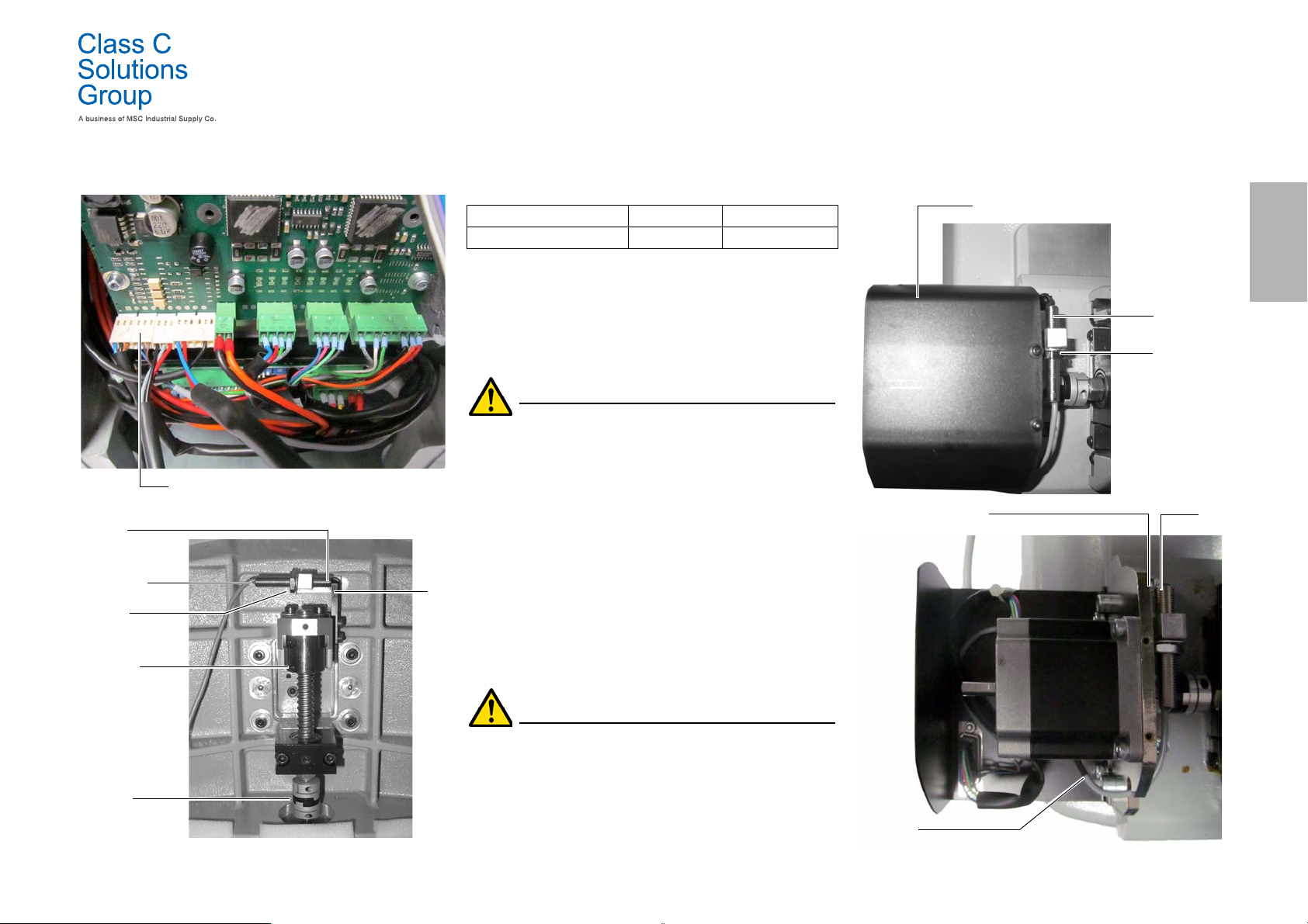
MAINTENANCE, DISMANTLING AND DISPOSAL
B
A
X sensor
Fastening
Carriage
Controls
to move
the carriage
nut
X sensor connection
Y sensor
B
A
Y sensor
Y sensor cover
Fastening
nut
connector
9.2.10 Replacing the Y axis sensor
Spare part description Code Frequency
Y axis sensor-994 RIC03412B When required
ENGLISH
Required tools
• 2mm hexagon wrench.
• 13mm adjustable wrench.
Safety warning
Before carrying out this operation disconnect the
power cable from the mains.
How to proceed:
• remove the jaw: first release it by rotating the knob that
locks it and then pull it out from its seat;
• remove the scrap material container;
• use the 2.5 mm wrench to remove the cover of jaw
assembly;
• take off the Y sensor cover by removing the 4 screws that
lock it;
• disconnect the sensor connector;
• use the adjustable wrench to loosen the nut that fastens
the sensor;
• unscrew and remove the sensor and replace it with a new
one;
• connect the connector;
• after fastening and locking the new sensor, move the
carriage towards it using the relevant controls.
IMPORTANT! Leave 0.02mm clearance between point A
and B.
• put back the cover, the scrap material container and the
jaw into their initial positions.
Class C Solutions Group BD LASER MAX Man. cod. B409652FG 21
Page 24
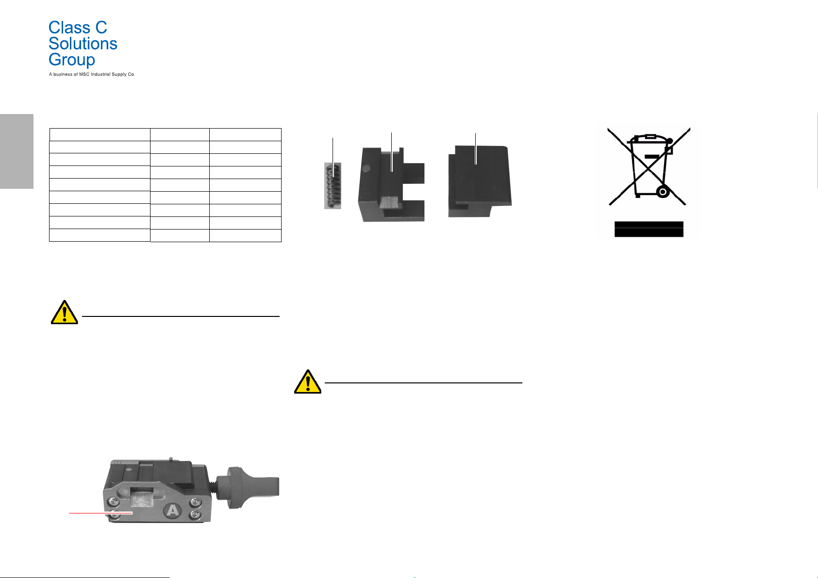
ENGLISH
A
C
B
B
9.2.11 Replacing jaw parts
Spare part description Code Frequency
Jaw knob A-994 RIC03314B When required
Jaw knob B994 RIC03316B When required
Jaw knob C994 RIC03318B When required
Jaw knob D-994 RIC03320B When required
Vice Jaws A-994 - Pair RIC03414B When required
Vice Jaws B994 - Pair RIC03416B When required
Vice Jaws C994 - Pair RIC03418B When required
Vice Jaws D-994 - Pair RIC03420B When required
Required tools
• 2mm hexagon wrench.
• 13mm adjustable wrench.
Safety warning
Before carrying out this operation disconnect the
power cable from the mains.
How to proceed:
To replace vices and springs you need to disassemble the jaw as described below:
• use the 2.5 mm hexagon wrench to remove the 4 screws
located in the front part of the jaw, remove the front cover (A);
• use the 3 mm hexagon wrench to remove the 2 screws
located at the bottom of the jaw;
• remove the vises (B) and/or springs (C) from the jaw and
replace them with new ones;
• re-assemble the jaw by going through the steps above in
reverse order.
MAINTENANCE, DISMANTLING AND DISPOSAL
9.3.0 Waste disposal
The disposal of waste generated by the machine shall be managed in
compliance with the legislation in force in the user's country. In Europe, machine shop rejections are classified as special waste and are
assimilated to metal wool when it comes to managing municipal solid
waste (MSW).
Such waste must be disposed of according to the legislation in force
in the user's country.
If machine shop rejections have been contaminated or contain toxic or
harmful substances they are considered as toxic -harmful waste and
disposed of accordingly in compliance with the legislation in force.
The user is responsible for correct waste management.
9.4.0 The WEEE directive
When disposal becomes necessary, the BD LASER MAX appliance is
to be consid ered as belonging to th e WEEE category (Waste Ele ctrical
and Electronic Equipment).
Class C Solutions Group has always taken great care to protect the
environment and complies with the legislative decree on WEEE that
has been in force since 13 /08/2005. As a consequence, in accordance
with the prescriptions of directive 2002/ 96/CE, this appliance cannot
be disposed of as household waste (in compliance with the special
symbol shown below).
• Whoever disposes of this appliance illegally or as
household waste will be subject to the sanctions foreseen
by current national legislation.
• According to the provisions of current national legislation,
this appliance cannot be disposed of as household waste.
Therefore, at the end of its lifecycle, after having carried
out the operations that are necessary for correct disposal,
the appliance must be taken to one of the differentiated
waste collection centres for electrical and electronic
waste from domestic households. Refer to the collection
centre in your own town, which will guarantee the
functionality, accessibility and suitably of the
differentiated collection systems, so that the final holder
and distributors can take the waste that they produce in
their area to collection centres, free of charge.
9.4.1 Disposal of the packing material
The packaging that contains the duplicator during transport is made
up of a cardboard box that can therefore be recycled as packaging.
In the event of disposal it is considered as normal urban waste and
can be taken to the designated collection points for paper.
22 BD LASER MAX Man. cod. B409652FG Class C Solutions Group
 Loading...