

Page 1
Outdoor Motion Sensor Wall Light
Utomhusbelysning med rörelsevakt
Utebelysning med bevegelsessensor
Seinävalaisin, jossa liiketunnistin
Außenleuchte mit Bewegungsmelder
EnglishSvenskaNorskSuomiDeutsch
Art.no Model
36-5059 EL270UPS WH
36-5060 EL270UPS BK
Ver. 20151009
Page 2

2
Page 3

Outdoor Motion Sensor Wall Light
Art.no 36-5059 Model EL270UPS WH (white)
36-5060 EL270UPS BK (black)
Please read theentire instruction manual before using theproduct and then save
it for future reference. We reserve theright for any errors in text or images and any
necessary changes made to technical data. If you have any questions concerning
technical problems please contact our Customer Services.
Safety
Warning: All light fittings must be installed in accordance with current safety
regulations to prevent life-threatening accidents. Theinstallation of this light fitting
should only be performed by someone with agood knowledge of electrical wiring.
If in doubt, contact aqualified electrician. Follow theinstructions carefully and keep
them for future reference.
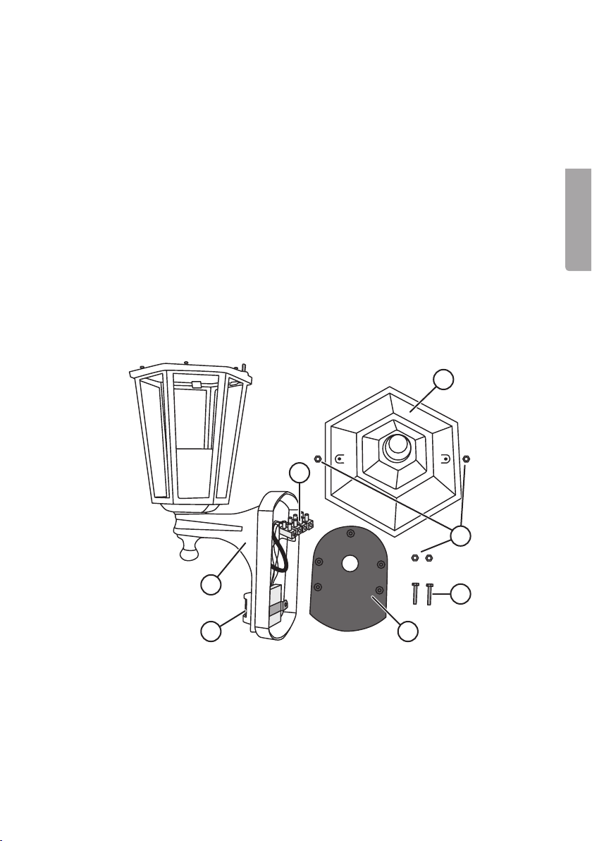
Description
4
3
English
1. PIR sensor
2. Bracket
3. Terminal block
4. Top cap
5. Cap nut (4 ×)
6. Mounting bolt (2 ×)
7. Wall plate
5
2
1
3
7
6
Page 4
English
Installation
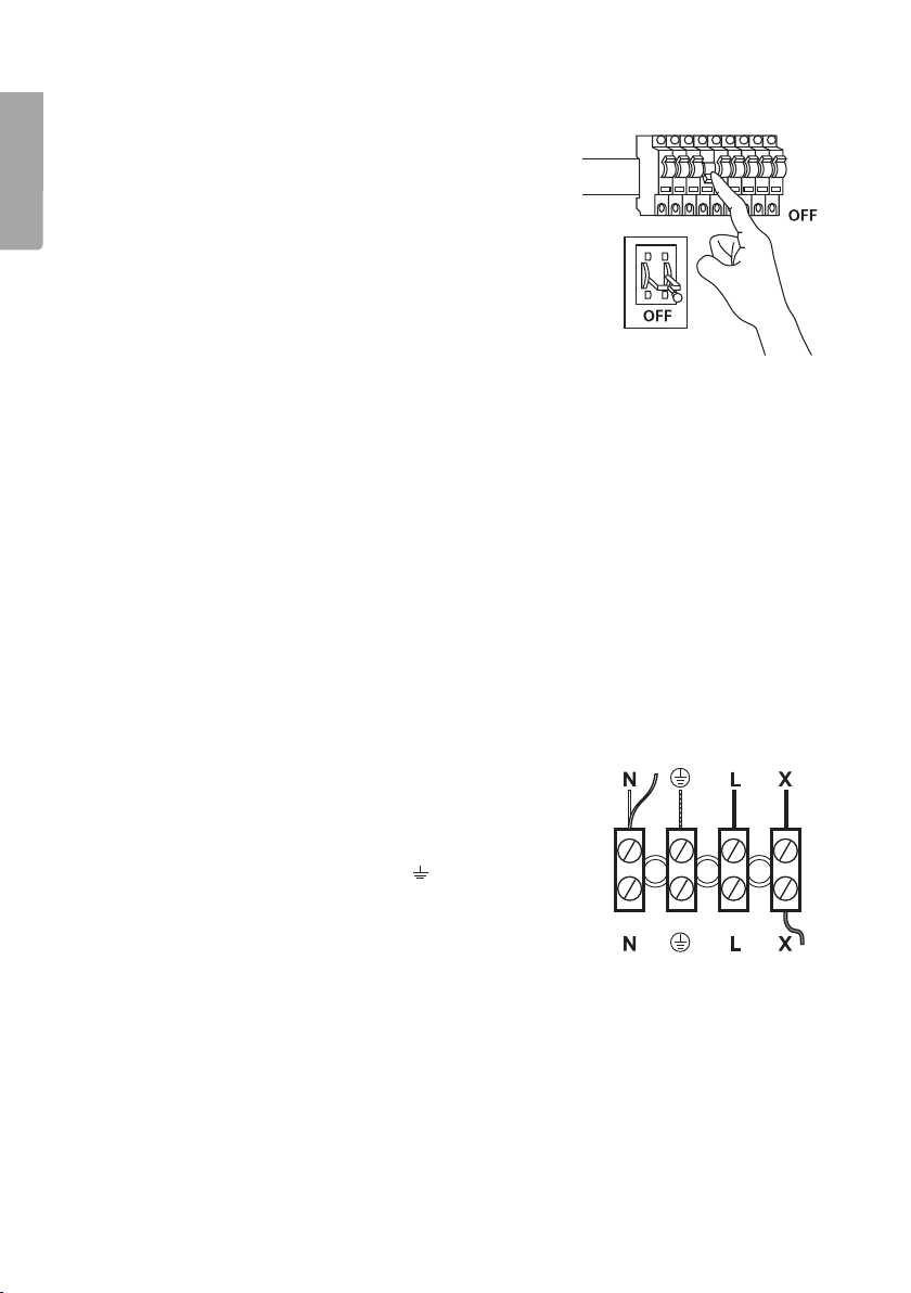
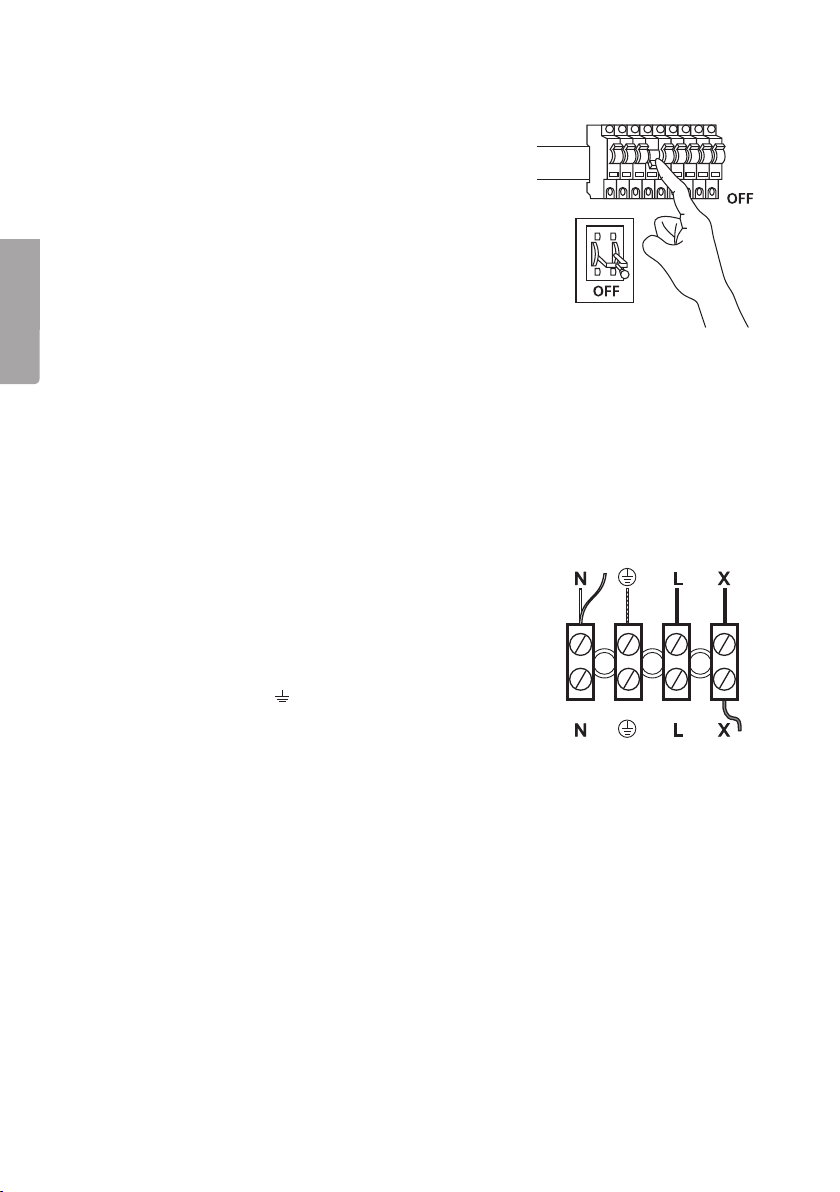
1. Warning: Always turn thepower off at thedistribution
box before installation (main power switch/
circuit breaker set to OFF, or fuse completely
disconnected).
2. Remove thecap nuts (5) at thefront of thelight and
remove thewall plate (7) from theback of thelight.
Keep thecap nuts and mounting bolts (6) close to
hand.
3. Make asmall hole for thepower supply cable in
therubber gasket of thewall plate and small holes
in theactual wall plate for screws used to fasten
theplate to thewall.
4. Feed thepower supply cable through thehole
in therubber gasket (or through thehole in
thebottom).
5. Depending on thetype of wall you have, you can
either screw thewall plate directly to thewall or
mark out where themounting holes need to be,
drill and insert wall plugs. Note: Thewall plate has
anarrow on it which should point upwards when
theplate is mounted. Push themounting bolts (6)
through thewall plate from theback before screwing
it to thewall.
6. Connect thepower lead to theterminal block as
shown below.
- Blue (neutral) connects to theterminal marked N.
- Brown or black (live) connects to theterminal
marked L.
- Yellow-green (earth) connects to theterminal
marked with theearth symbol (
- TheX terminal is not to be touched; it already
has ared cable.
7. Hold thebracket (2) against thewall plate and fasten
it using two cap nuts on thefront.
8. Remove thetop cap (4) by undoing thecap nuts.
9. Screw in alight bulb (max 60W, E27) (sold separately).
10. Refit thetop cap and switch themain power back on.
).
Note: This outdoor light is fitted with atwilight switch
which prevents it from coming on during daylight hours.
4
Page 5

Placement
Thefollowing points should be considered before installation:
1. ThePIR sensor on thelight is designed for optimum function when it is mounted
2.5 metres above ground.
2. Avoid pointing thePIR sensor towards hot surfaces or heat sources such as
ventilation ducts.
3. Avoid mounting theoutdoor light close to strong magnetic fields as this may cause
thelight to be activated unnecessarily.
4. ThePIR sensor is most effective for detecting motion moving across thesurveillance
area and less effective at detecting movement towards it.
5. ThePIR sensor works best in low humidity and at anambient temperature around
20 °C. Rising and falling temperatures and increased humidity can contribute to
agradual decreased sensitivity in both detection angle and distance.
6. Avoid pointing thePIR sensor towards reflective surfaces such as white walls or water.
Setting
There are two controls on thebottom of thelight, SENS (activation sensitivity) and
TIME (duration of activation).
English
• SENS (sensitivity for activation)
TheSENS control (on theleft when facing thelight) controls thesensitivity, i.e. how
much of achange in temperature is required in order to activate thePIR sensor.
Turning theknob anticlockwise lowers thesensitivity (thelight requires agreater
change in temperature to be activated) turning it clockwise increases thesensitivity
(thelight requires less of achange in temperature in order to be activated).
• TIME (duration of activation)
TheTIME control (on theright when facing thelight) controls theactivation time.
Thelength of activation can be adjusted from 10 (+/-5) seconds to 4 (+/-1)
minutes. Turn thecontrol knob anticlockwise to shorten theduration of activation
or clockwise to lengthen theduration of activation.
Note: Once thepower supply to thelight has been switched on, thelight will
enter “warm-up mode” for about 30 seconds (within 1 minute). It will then switch
automatically to “auto” mode.
5
Page 6

English
Responsible disposal
This symbol indicates that this product should not be disposed of with
general householdwaste. Thisapplies throughout theentire EU. Inorder
to prevent any harm to theenvironment or health hazards caused by
incorrect waste disposal, theproduct must be handed in for recycling
so that thematerial can be disposed of in aresponsible manner.
Whenrecycling your product, take it to your local collection facility or
contact theplace of purchase. Theywill ensure that theproduct is
disposed of in anenvironmentally sound manner.
Specifications
Voltage 230 V AC, 50 Hz
Bulb Max 1 × 60W, E27 (sold separately)
IP rating IP33
Motion detector PIR sensor with twilight switch
Detection angle 110°
Range approx. 10m
6
Page 7
Utomhusbelysning med rörelsevakt
Art.nr 36-5059 Modell EL270UPS WH (vit)
36-5060 EL270UPS BK (svart)
Läs igenom hela bruksanvisningen före användning och spara den sedan för framtida
bruk. Vi reserverar oss för ev. text- och bildfel samt ändringar av tekniska data.
Vid tekniska problem eller andra frågor, kontakta vår kundtjänst (se adressuppgifter
på baksidan).
Säkerhet
Varning! Alla belysningsarmaturer måste installeras korrekt för att inte utgöra livsfara.
Endast personer med nödvändig kunskap om elinstallationer får utföra denna installation.
Saknas denna kunskap, kontakta fackman. Följ anvisningen noggrant och spara den
för senare bruk.
Beskrivning
4
3
5
1. PIR-sensor
2. Fäste
3. Kopplingsplint
4. Lock
5. Kupolmuttrar (4 ×)
6. Fästskruvar (2 ×)
7. Väggplatta
2
1
7
6
Svenska
7
Page 8
Installation
1. Varning! Bryt alltid strömmen före installation
2. Lossa kupolmuttrarna (5) på armaturens framsida,
3. Gör ett litet hål (för inkommande ledare) i väggplattans
Svenska
4. För igenom inkommande ledare genom väggplattans
5. Beroende på väggbeklädnad: skruva fast väggplattan
6. Anslut inkommande ledare till kopplingsplinten enligt
7. Tryck fast fästet (2) mot väggplattan och skruva fast
8. Ta bort locket (4) genom att skruva av kupolmuttrarna.
9. Skruva i en ljuskälla (max 60 W, E27) (säljs separat).
10. Montera locket och slå därefter till strömmen.
(strömbrytare och säkring i läge OFF, eller
säkringen urskruvad).
och ta bort väggplattan (7) på baksidan. Håll rätt
på kupolmuttrar och fästskruvar (6).
gummitätning samt små hål i väggplattan till skruvarna
som används för fastsättning på väggen.
gummitätning (eller genom hålet på undersidan).
direkt på väggen eller märk upp och borra fästhålen
i väggen och använd plugg. Obs! Väggplattan har
en pilmarkering och den måste monteras med pilen
uppåt. Tryck in fästskruvarna (6) från baksidan av
väggplattan innan den skruvas fast på väggen.
följande schema:
- Blå (nolledare) ansluts till kopplingsplintens
ingång märkt N.
- Brun eller svart (fas) ansluts till kopplingsplintens
ingång märkt L.
- Gul-grön (jordledare) ansluts till ingången märkt
med jordsymbol (
- Ingången X ska inte röras, den har redan en
röd kabel.
de två kupolmuttrarna på framsidan.
).
Obs! Utomhusbelysningen är försedd med skymningsrelä som gör att den endast tänds vid mörker.
8
Page 9

Placering
Tänk på detta när du ska välja placering:
1. Utomhusbelysningens rörelsevakt är konstruerad för att fungera optimalt när den
är monterad 1,5 till 2,5 meter över marken.
2. Undvik att rikta rörelsevakten mot heta ytor som ventilationsöppningar.
3. Undvik att montera utomhusbelysningen i närheten av starka magnetfält, det kan
medföra att ljuset tänds i onödan.
4. Rörelsevakten är mest effektiv vid rörelser tvärs över övervakningsområdet och den
är minst känslig för rörelser rakt mot belysningen.
5. Rörelsevakten fungerar bäst när omgivningens temperatur är 20 °C och vid låg
luftfuktighet. Stigande/sjunkande temperatur och ökande luftfuktighet kan medföra
att detekteringsvinkel och detekteringsavstånd minskar gradvis.
6. Undvik att rikta rörelsevakten mot stora vita ytor eller vattenytor.
Inställning
På undersidan av utomhusbelysningen finns två reglage, SENS (känslighet för tillslag)
och TIME (aktiveringstid).
Svenska
• SENS (känslighet för tillslag)
Reglaget SENS (det vänstra sett från framsidan) styr känsligheten, d.v.s. hur stor
indikerad temperaturändring som krävs för att rörelsevakten ska aktiveras. Vrid
moturs för lägsta känslighet (belysningen kräver större temperaturändring för att
aktiveras) och medurs för högsta känslighet (belysningen kräver mindre temperaturändring för att aktiveras).
• TIME (aktiveringstid)
Reglaget TIME (det högra sett från framsidan) styr aktiveringstiden. Tiden kan
justeras från 10 (+/-5) sekunder till 4 (+/-1) minuter. Vrid moturs för att minska
aktiveringstiden och medurs för att öka aktiveringstiden.
Obs! När du har kopplat in ström på utomhusbelysningen, ställer den in sig i ”uppvärmningsläge” under ca 30 sekunder (inom en minut). Sedan skiftar den automatiskt till autoläge.
9
Page 10

Avfallshantering
Denna symbol innebär att produkten inte får kastas tillsammans
med annat hushållsavfall. Dettagäller inom hela EU. Föratt
förebygga eventuell skada på miljö och hälsa, orsakad av felaktig
avfallshantering,ska produkten lämnas till återvinning så att
materialet kan tas omhand på ettansvarsfulltsätt. Närdu lämnar
produkten till återvinning, använd dig av de returhanteringssystem
som finns där du befinner dig eller kontakta inköpsstället.
Dekan se till att produkten tas om hand på ettför miljön
tillfredställandesätt.
Svenska
Specifikationer
Spänning 230 V AC, 50 Hz
Ljuskälla Max 1 × 60 W, E27 (säljs separat)
Kapsling IP33
Rörelsevakt (PIR) med skymningsrelä
Avkänningsvinkel 110°
Räckvidd ca 10 m
10
Page 11

Utebelysning med bevegelsessensor
Art.nr. 36-5059 Modell EL270UPS WH (hvit)
36-5060 EL270UPS BK (svart)
Les brukerveiledningen grundig før produktet tas i bruk og ta vare på den for framtidig bruk.
Vi reserverer oss mot ev. feil i tekst og bilde, samt forandringer av tekniske data. Ved tekniske
problemer eller spørsmål, ta kontakt med vårt kundesenter.
Sikkerhet
Advarsel! Alle lysarmaturer må installeres fagmessig riktig for ikke å være til fare for
liv og helse. Kun personer med nødvendig kunnskap om elektriske installasjoner kan
utføre denne monteringen. Det vil si at all montering av fast installasjon må foretas av
registrert installasjonsvirksomhet! Følg instruksjonene nøye og ta vare på anvisningen
til ev. seinere bruk.
Beskrivelse
1. PIR-sensor
2. Feste
3. Koblingsplint
4. Lokk
5. Hettemuttere (4 ×)
6. Festeskruer (2 ×)
7. Veggplate
Norsk
4
3
5
2
1
7
6
11
Page 12

Norsk
Installasjon
1. Advarsel! Bryt alltid strømmen før installasjon.
Strømbryter og sikring skal være i OFF-stilling
(sikring skal ev. være skrudd ut).
2. Løsne på hettemutteren (5) på forsiden på armaturen
og fjern veggplaten (7). Hold rede på hettemutrene
og festeskruene (6).
3. Lag et lite hull (til innkommende leder) i gummitetningen på veggplaten og små hull i til skruene
som skal feste platen på veggen.
4. Før lederen inn gjennom gummitetningen på veggplaten eller gjennom hullet på undersiden.
5. Avhengig av type veggkledning: Fest veggplaten
rett på veggen, eller bygg opp med distanseplugg.
Obs! Veggplaten har en pilmarkering og må monteres
med pilen oppover. Trykk festeskruen (6) inn fra baksiden av veggplaten før den skrus fast på veggen.
6. Innkommende leder kobles til koblingsplinten som
vist på skjema:
- Blå kobles til skrue merket N eller L.
- Brun eller svart kobles til N eller L.
- Gul-grønn (jord) kobles til inngangen merket med
jordsymbol (
- Inngangen X skal ikke røres. Den har allerede en
rød kabel.
7. Trykk (2) fast mot veggplaten og skru fast de to
hettemutrene på framsiden.
8. Lokket (4) fjernes ved at kuppelmutrene skrus ut.
9. Skru i lyskilden (maks 60 W, E 27) (selges separat).
10. Monter lokket og koble deretter strømmen til.
).
Obs! Utebelysningen er utstyrt med et skumringsrelé
som gjør at det kun er tent når det er mørkt.
12
Page 13

Plassering
Husk følgende når plassering skal velges:
1. Sensoren fungerer optimalt ved montering i en høyde på 1,5 til 2,5 meter over bakkenivå.
2. Unngå at sensoren vendes mot varme flater som f.eks. ventilasjonsåpninger.
3. Unngå montering nær sterke magnetfelt. Det kan føre til at lyset tennes unødvendig.
4. Sensoren er mest effektiv ved bevegelse på tvers av overvåkingsområdet og minst
følsom for bevegelser rett mot sensoren.
5. Bevegelsessensoren fungerer best når omgivelsestemperaturen er 20 °C og
ved lav luftfuktighet. Endringer i temperatur og økende luftfuktighet kan føre til at
deteksjonsvinkelen og deteksjonsavstanden reduseres.
6. Unngå å montere bevegelsessensoren slik at den vender mot store hvite flatter
eller vannflater.
Innstilling
På sensorens underside er det to brytere. SENS (følsomhet for tilslag) og
TIME (aktiveringstid).
Norsk
• SENS (følsomhet for tilslag)
SENS-bryteren (den venstre bryteren sett fra forsiden) styrer følsomheten, dvs. hvor
stor indikert temperaturendring som må til for at bevegelsessensoren skal aktiveres.
Drei moturs for å stille på den laveste følsomheten. Belysningen krever da større
temperaturendring for å aktiveres. Drei medurs for høy følsomhet.
• TIME (aktiveringstid)
TIME-bryteren (den høyre sett fra framsiden) styrer aktiveringstiden. Tiden kan
justeres fra 10 (+/-5) sekunder til 4 (+/-1) minutter. Drei moturs for å redusere
aktiveringstiden og medurs for å øke den.
Obs! Når du har koblet til strøm på bevegelsesdetektoren, stiller den seg inn i «oppvarmingsmodus» i ca. 30 sekunder (innen 1 minutt). Deretter skifter den automatisk til automodus.
13
Page 14

Norsk
Avfallshåndtering
Symbolet viser til at produktet ikke skal kastes sammen med
husholdningsavfallet. Dettegjelder ihele EØS-området. Foråforebygge
eventuelle skader på helse og miljø, som følge av feil håndtering av
avfall, skal produktet leveres til gjenvinning, slik at materialet blir tatt
hånd om på enansvarsfullmåte. Benytt miljøstasjonene som er derdu
befinner deg eller ta kontakt med forhandler. Dekan se til at produktet
blir behandlet på entilfredsstillende måte som gagner miljøet.
Spesifikasjoner
Spenning 230 V AC, 50 Hz
Lyskilde Maks 1 × 60 W, E27 (selges separat)
Kapsling IP33
Bevegelsessensor med skumringsrelé
Avfølingsvinkel 110°
Rekkevidde ca. 10 m
14
Page 15

Seinävalaisin, jossa liiketunnistin
Tuotenumero 36-5059 Malli EL270UPS WH (valkoinen)
36-5060 EL270UPS BK (musta)
Lue käyttöohje ennen tuotteen käyttöä ja säilytä se tulevaa tarvetta varten. Pidätämme
oikeuden teknisten tietojen muutoksiin. Emme vastaa mahdollisista teksti- tai kuvavirheistä.
Jos tuotteeseen tulee teknisiä ongelmia, ota yhteys myymälään tai asiakaspalveluun
(yhteystiedot käyttöohjeen lopussa).
Turvallisuus
Varoitus! Valaisimet tulee asentaa aina asianmukaisesti hengenvaaran välttämiseksi.
Asennuksen saa suorittaa ainoastaan henkilö, jolla on riittävät taidot sähköasennusten
tekemiseen. Jos sinulla ei ole riittäviä taitoja, ota yhteys sähköasentajaan. Noudata
käyttöohjetta tarkasti ja säilytä se tulevaa tarvetta varten.
Tuotteen kuvaus
4
3
Suomi
1. PIR-anturi
2. Kiinnike
3. Kytkentärima
4. Kansi
5. Kupolimutterit (4 kpl)
6. Kiinnitysruuvit (2 kpl)
7. Seinälevy
5
2
1
15
7
6
Page 16

Suomi
Asentaminen
1. Varoitus! Katkaise sähkövirta ennen valaisimen
asentamista (virtakytkin ja sulake OFF-asennossa tai
sulake irrotettuna).
2. Avaa valaisimen etuosassa olevat kupolimutterit (5)
ja irrota valaisimen takaosan seinälevy (7). Pidä
kupolimutterit ja kiinnitysruuvit (6) tallessa.
3. Tee pieni reikä johtimille seinälevyn kumitiivisteeseen
sekä pienet reiät seinälevyyn ruuveille seinään kiinnittämistä varten.
4. Vie johtimet seinälevyn kumitiivisteen läpi (tai alaosan
reiän läpi).
5. Seinämateriaalista riippuen kiinnitä seinälevy ruuveilla
suoraan seinään tai merkitse ja poraa kiinnitysreiät
seinään ja käytä tulppia. Huom.! Asenna seinälevy
niin, että siinä oleva nuoli osoittaa ylöspäin. Paina
kiinnitysruuvit (6) seinälevyyn taustapuolelta ennen
seinälevyn kiinnittämistä seinään.
6. Liitä johtimet kytkentärimaan seuraavan kaavion
mukaisesti.
- Sininen (nollajohdin) liitetään kytkentäriman
sisääntuloon, joka on merkitty N-kirjaimella.
- Ruskea tai musta (vaihejohdin) liitetään
kytkentäriman sisääntuloon, joka on
merkitty L-kirjaimella.
- Keltavihreä (maajohdin) liitetään kytkinriman
sisääntuloon, joka on merkitty maasymbolilla (
- Liitäntää X ei tarvitse muuttaa, siinä on jo
punainen johto.
7. Paina kiinnike (2) seinälevyyn ja ruuvaa kaksi kupolimutteria paikalleen etupuolelta.
8. Irrota kansi (4) avaamalla kupolimutterit.
9. Laita lamppu (enint. 60 W, E27) paikalleen (myydään
erikseen).
10. Kiinnitä kansi paikalleen ja liitä sähkövirta valaisimeen.
).
Huom.! Ulkovalaisimessa on hämäräkytkin, joka sytyttää
valaisimen pimeän tultua.
16
Page 17

Sijoittaminen
Ota seuraavat asiat huomioon valaisimen sijoittamisessa:
1. Ulkovalaisimen liiketunnistin toimii parhaiten, kun se on sijoitettu 1,5–2,5 metriä
maanpinnan yläpuolelle.
2. Vältä liiketunnistimen suuntaamista kohti kuumia pintoja, kuten tuuletusaukkoja.
3. Vältä ulkovalaisimen asentamista vahvojen magneettikenttien läheisyyteen, sillä ne
voivat vaikuttaa hämäräkytkimen toimintaan.
4. Liiketunnistin reagoi parhaiten tunnistusalueen poikki kulkevaan liikkeeseen ja
heikoiten suoraan valaisinta kohti suuntautuvaan liikkeeseen.
5. Liiketunnistin toimii parhaiten ympäristön lämpötila ollessa +20 °C ja ilmankosteuden
ollessa matala. Lämpötilan nousu tai lasku ja ilmankosteuden nousu voivat pienentää
havaitsemiskulmaa ja -etäisyyttä asteittain.
6. Vältä liiketunnistimen suuntaamista suuria valkoisia pintoja tai vedenpintaa kohti.
Asentaminen
Ulkovalaisimen pohjassa on kaksi säädintä, SENS (liiketunnistimen aktivoitumisherkkyys)
ja TIME (aktivoitumisaika).
Suomi
• SENS (liiketunnistimen aktivoitumisherkkyys)
Säädin SENS (edestä katsottuna vasemmanpuoleinen säädin) ohjaa liiketunnistimen
aktivoitumisherkkyyttä, eli sitä, miten suuri lämpötilan muutos aktivoi liiketunnistimen.
Valitse alhaisin herkkyys kääntämällä säädintä vastapäivään (liiketunnistin aktivoituu
vasta suuremmasta lämpötilan muutoksesta) ja suurin herkkyys kääntämällä säädintä
myötäpäivään (liiketunnistin aktivoituu jo pienemmästä lämpötilan muutoksesta).
• TIME (aktivoitumisaika)
Säädin TIME (edestä katsottuna oikeanpuoleinen säädin) ohjaa liiketunnistimen
aktivoitumisaikaa. Aikaa voidaan säätää 10 (+/-5) sekunnista 4 (+/-1) minuuttiin.
Lyhennä aktivoitumisaikaa kääntämällä säädintä vastapäivään ja pidennä aktivoitumisaikaa kääntämällä säädintä myötäpäivään.
Huom.! Kun olet liittänyt sähkövirran ulkovalaisimeen, valaisin siirtyy minuutin kuluessa
lämpenemistilaan 30 sekunnin ajaksi. Tämän jälkeen valaisin siirtyy automaattisesti
valmiustilaan.
17
Page 18

Suomi
Kierrättäminen
Tämä symboli tarkoittaa, että laitetta ei saa laittaa kotitalousjätteen
sekaan. Ohjekoskee koko EU-aluetta. Virheellisestä kierrättämisestä
johtuvien mahdollisten ympäristö- ja terveyshaittojen ehkäisemiseksi
laite tulee viedä kierrätettäväksi, jotta materiaali voidaan käsitellä
vastuullisella tavalla. Kierrätä laite käyttämällä paikallisia kierrätysjärjestelmiä tai ota yhteys ostopaikkaan. Ostopaikassa laite kierrätetään
vastuullisella tavalla.
Tekniset tiedot
Jännite 230 V AC, 50 Hz
Valonlähde Enint. 1 × 60 W, E27 W (myydään erikseen)
Suojausluokka IP33
Liiketunnistin (PIR) ja hämäräkytkin
Tunnistuskulma 110°
Kantama noin 10 m
18
Page 19

Außenleuchte mit Bewegungsmelder
Art.Nr. 36-5059 Modell EL270UPS WH (weiß)
36-5060 EL270UPS BK (schwarz)
Vor Inbetriebnahme diekomplette Bedienungsanleitung durchlesen und aufbewahren.
Irrtümer, Abweichungen und Änderungen behalten wir uns vor. Bei technischen
Problemen oder anderen Fragen freut sich unser Kundenservice über eine
Kontaktaufnahme (Kontakt siehe Rückseite).
Sicherheitshinweise
WARNUNG: Wand- und Deckenleuchten müssen korrekt installiert sein, damit sie
keine Gefahr auszumachen. Solche Installationen nur von Personen mit ausreichenden
Kenntnissen über Elektroinstallationen durchführen lassen. Sind dieKenntnisse nicht
ausreichend unbedingt einen Fachmann kontaktieren. DieBedienungsanleitung genau
befolgen und für den späteren Bedarf aufheben.
Beschreibung
4
1. PIR-Sensor
2. Halterung
3. Lüsterklemme
4. Abdeckung
5. Hutmutter (4 ×)
6. Montageschraube (2 ×)
7. Wandplatte
3
5
2
1
19
7
6
Deutsch
Page 20

Installation
1. Warnung! Vor dem Einbau immer dieStromversorgung
2. DieHutmuttern (5) ander Vorderseite der Leuchte lösen
3. Ein kleines Loch (für den zuführenden Leiter) in dieGummi-
4. Den zuführenden Leiter durch dieGummidichtung der
5. Je nach Art der Wandverkleidung: DieWandplatte
6. DieStromzufuhr gemäß dem folgenden Schaltbild
Deutsch
7. DieHalterung (2) andieWandplatte drücken und
8. Dieanderen zwei Hutmuttern abschrauben um
9. Ein passendes Leuchtmittel (max. 60 W, E27,
10. DieAbdeckung anbringen und danach den Strom
trennen (Geräteschalter und Sicherung in Position AUS,
oder Sicherung herausgeschraubt).
und dieWandplatte (7) von der Rückseite abnehmen.
DieHutmuttern und Montageschrauben (6) übersichtlich
bereitlegen.
dichtung der Wandplatte machen. In dieWandplatte
ebenso kleine Löcher für dieSchrauben machen,
diezur Befestigung ander Wand gedacht sind.
Wandplatte führen (oder durch dasLoch ander Unterseite).
direkt festschrauben oder zuerst Bohrlöcher markieren
und vorbohren sowie geeignete Dübel verwenden.
Hinweis: DiePfeilmarkierung der Wandplatte beachten
und diePlatte mit dem Pfeil nach oben montieren.
DieMontageschrauben (6) von hinten in dieWandplatte
drücken, bevor diese ander Wand festgeschraubt wird.
anschließen:
- Blau (Neutralleiter) wird anden Eingang der Anschlussklemme mit Kennzeichnung N angeschlossen.
- Braun oder Schwarz (Phase) wird anden Eingang der
Anschlussklemme mit Kennzeichnung L angeschlossen.
- Gelb-Grün (Schutzleiter) wird anden Eingang mit
dem Erde-Symbol angeschlossen (
- Den Eingang X nicht verändern, dieser hat bereits
ein angeschlossenes rotes Kabel.
diezwei Hutmuttern ander Vorderseite festschrauben.
dieAbdeckung (4) zu entfernen.
separat erhältlich) eindrehen.
einschalten.
).
Hinweis: DieAußenbeleuchtung ist mit einem Dämmerungsschalter versehen, sodass sie nur bei Dunkelheit einschaltet.
20
Page 21

Platzierung
Bei der Wahl des Installationsorts Folgendes beachten:
1. Der Bewegungsmelder der Beleuchtung ist so konstruiert, dass er in einer Position
in Höhe von 1,5 bis 2,5 Metern über dem Boden optimal funktioniert.
2. Den Bewegungsmelder möglichst nicht auf heiße Oberflächen, z. B. Belüftungsöffnungen, ausrichten.
3. DieAußenbeleuchtung nicht in der Nähe von starken Magnetfeldern anbringen.
Hierdurch kann dasLicht unnötigerweise eingeschaltet werden.
4. Bei Bewegungen quer über den Senorbereich ist der Bewegungsmelder am
effektivsten. Am wenigsten empfindlich ist er für Bewegungen, diedirekt auf
dieBeleuchtung zukommen.
5. Der Bewegungsmelder funktioniert am besten bei einer Umgebungstemperatur
von 20 °C und bei niedriger Luftfeuchtigkeit. Steigende/sinkende Temperaturen
und steigende Luftfeuchtigkeit können dazu führen, dass der Erkennungswinkel
und -abstand sich schrittweise verringern.
6. Den Bewegungsmelder möglichst nicht auf große weiße Flächen oder Wasser
ausrichten.
Einstellen
Ander Unterseite der Leuchte sind zwei Regler zu finden: SENS (Empfindlichkeit der
Einschaltung) und TIME (Aktivierungszeit).
• SENS (Empfindlichkeit der Einschaltung über Körpertemperatur)
Der Regler SENS (der linke von vorne aus gesehen) steuert dieEmpfindlichkeit, d.h.
er entscheidet welche Temperaturveränderung nötig ist um den Bewegungsmelder
zu aktivieren. Gegen den Uhrzeigersinn für diegeringste Empfindlichkeit drehen
(dieLeuchte benötigt jetzt größere Temperaturveränderungen zur Aktivierung) und
mit dem Uhrzeigersinn für diehöchste Empfindlichkeit drehen (dieLeuchte benötigt
kleinere Temperaturveränderungen für eine Aktivierung).
21
Deutsch
Page 22

• TIME (Aktivierungszeit)
Der Regler TIME (der rechte, von vorne aus gesehen) bestimmt dieAktivierungszeit.
DieZeit kann von 10 (±5) Sekunden bis 4 (±1) Minuten eingestellt werden. Zur
Verringerung der Aktivierungszeit gegen den Uhrzeigersinn drehen und zur Erhöhung
der Aktivierungszeit im Uhrzeigersinn drehen.
Hinweis: Nach Einschalten der Stromversorgung zur Außenleuchte, geht diese innerhalb einer Minute in den Aufwärmmodus über (ca. 30 Sekunden lang). Anschließend
geht dieLeuchte automatisch in den Automodus über.
Hinweise zur Entsorgung
Dieses Symbol zeigt an, dass dasProdukt nicht gemeinsam mit
demHaushaltsabfall entsorgt werdendarf. Diesgilt in dergesamten EU.
Ummöglichen Schäden für dieUmwelt und Gesundheit vorzubeugen,
diedurch fehlerhafte Abfallentsorgung verursacht werden, dieses
Produkt zum verantwortlichen Recycling abgeben um dienachhaltige
Wiederverwertung von stofflichen Ressourcen zu fördern.
BeiderAbgabe des Produktes bitte dievorhandenen Recycling- und
Sammelstationen benutzen oder den Händler kontaktieren. Dieser kann
dasProdukt auf eine umweltfreundliche Weise recyceln.
Technische Daten
Spannung 230 V AC, 50 Hz
Leuchtmittel Max. 1 × 60 W, E27 (separat erhältlich)
Schutzart IP33
Bewegungsmelder (PIR) mit Dämmerungsschalter
Erfassungsbereich 110°
Reichweite ca. 10 m
Deutsch
22
Page 23

23
Page 24

Sverige
Kundtjänst tel: 0247/445 00
fax: 0247/445 09
e-post: kundservice@clasohlson.se
Internet www.clasohlson.se
Post Clas Ohlson AB, 793 85 INSJÖN
Norge
Kundesenter tlf.: 23 21 40 00
faks: 23 21 40 80
e-post: kundesenter@clasohlson.no
Internett www.clasohlson.no
Post Clas Ohlson AS, Postboks 485 Sentrum, 0105 OSLO
Suomi
Asiakaspalvelu puh.: 020 111 2222
sähköposti: asiakaspalvelu@clasohlson.fi
Internet www.clasohlson.fi
Osoite Clas Ohlson Oy, Maistraatinportti 4 A, 00240 HELSINKI
Great Britain
Customer Service contact number: 020 8247 9300
e-mail: customerservice@clasohlson.co.uk
Internet www.clasohlson.co.uk
Postal 10 – 13 Market Place
Kingston Upon Thames
Surrey
KT1 1JZ
Deutschland
Kundenservice Unsere Homepage www.clasohlson.de besuchen und
auf Kundenservice klicken.
 Loading...