

Page 1
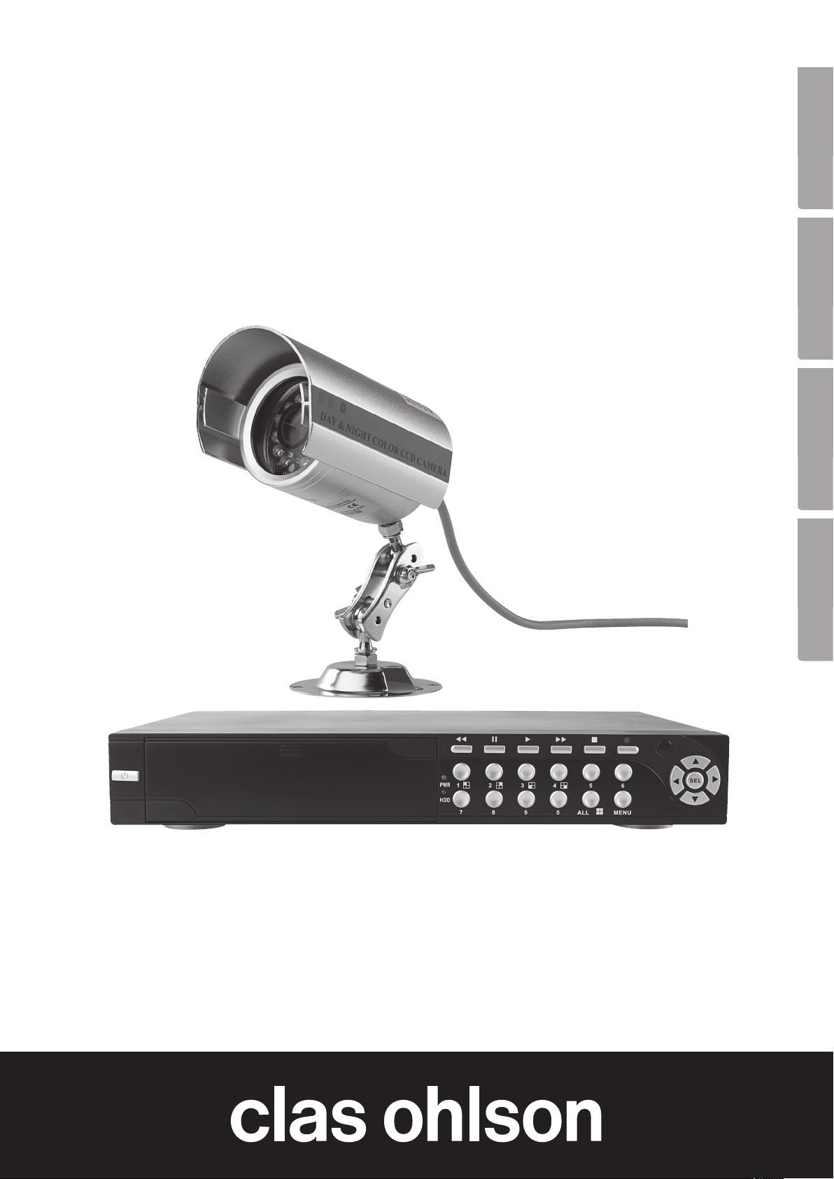
Digital Video Recorder
Digital Videoinspelare DVR
Digital Videospiller DVR
Digitaalinen videotallennin DVR
EnglishSvenskaNorskSuomi
Art.no. Model
36-3777 D6004CK
Ver. 201007
Page 2

2
Page 3

Digital Video Recorder
Art.no. 36-3777 Model D6004CK
Please read the entire instruction manual before use and save it for future reference. We reserve the right for any
errors in text or images and for making any necessary technical changes to this document. If you should have
any questions concerning technical problems please contact our Customer Services.
1. Description
• MPEG4 compression
• 4 channels: 4 BNC camera inputs – 2 BNC video outputs
• System format: NTSC/PAL
• Motion detector with settings for area and sensitivity
• Time scheduled, alarm, or motion detection recording modes
• Support for hard disks up to 1 TB (SATA)
• Supports PTZ control via Port 485
• Monitors and controls equipment over the Internet (broadband connection required)
• Built-in USB 2.0 port for computer back-up or to a USB flash drive
1.1 Safety
• The DVR is only intended for indoor use. Do not expose it to moisture.
• Only use the included adaptor (12 V, 5 A, + centre pin).
English
• The cameras are waterproof, however they should be mounted in as protective environment as possible.
• Be extra careful with the cable connections for the camera. These must be protected against moisture
penetration since they are exposed and offer no natural protection against moisture and damp.
3
Page 4
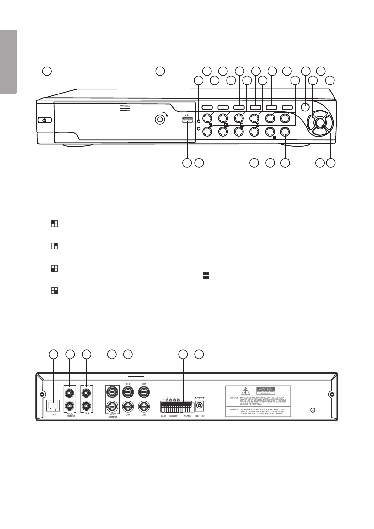
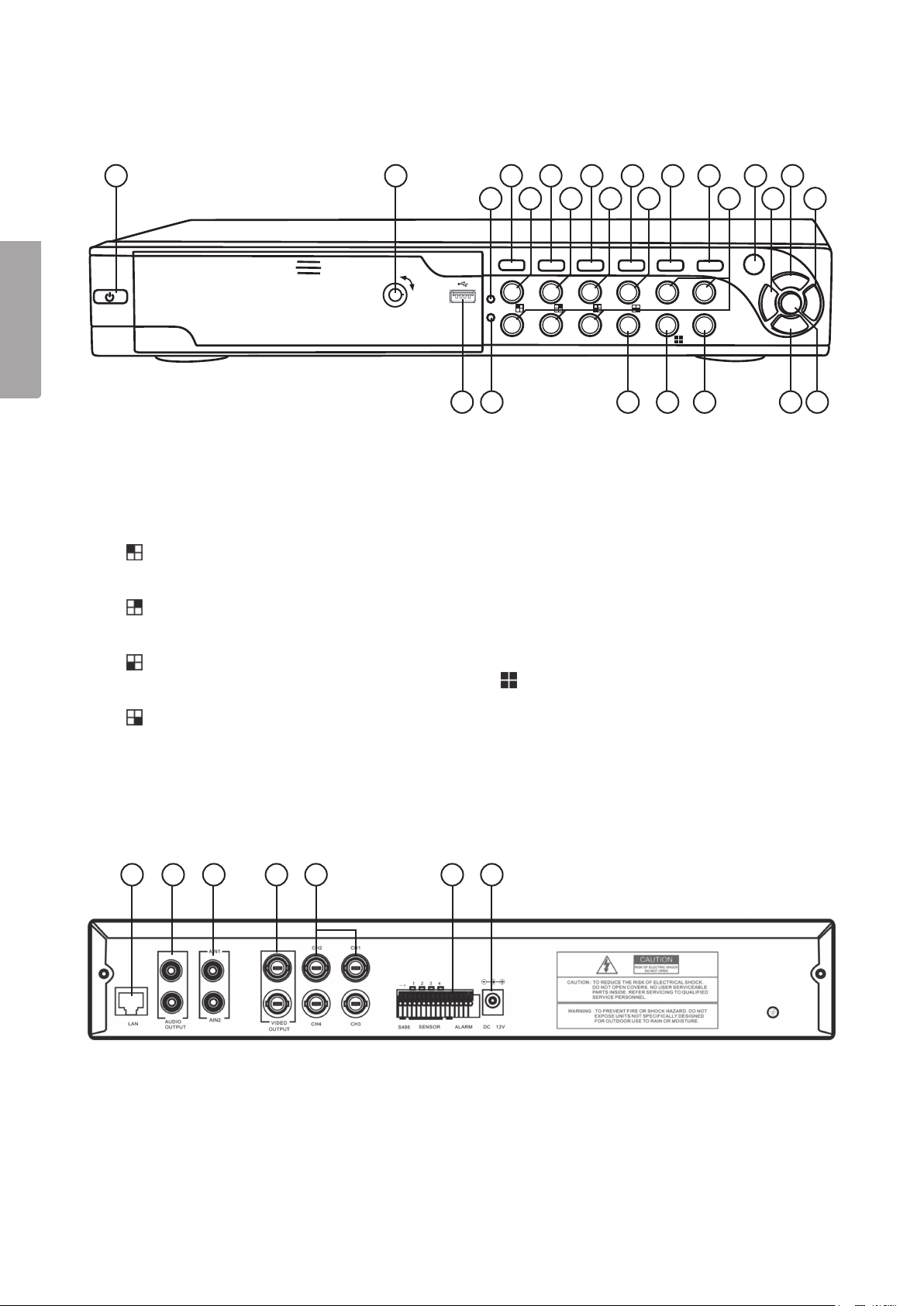
2. Buttons and functions
2.1 Front panel 4-channel DVR
English
1
1. Power switch
2. Hard disk lock
3. PWR LED (Power indicator)
] Rewind
4. [
5. [1
6. [
7. [2
8. [
9. [3
10. [
11. [4
12. [
13. [
] Channel 1
] Pause
] Channel 2
] Play
] Channel 3
] Fast forward
] Channel 4
] Stop
] Record
2 8 10 12
19 20
4 156 13
3
5 7
PWR 1 2 3 4 5 6
HDD
7 8 9 0 ALL MENU
14. [5–9] Number 5 to Number 9
15. IR sensor
16. [] Left arrow
17. [] Up arrow
] Right arrow
18. [
19. Hard disk drawer and USB connection
(Inside the cover)
20. HDD LED
21. [0] Mute (temporarily turns off volume)
22. [
23. [MENU] Exits the menu
24. [] Down arrow
25. [SEL] Select
] Displays all cameras
9 11 14 16 18
21 22 23 24
17
SEL
25
2.2 Back panel 4-channel DVR
1 2 3 4 5 6 7
1. LAN – Network cable connection
2. Audio output
3. Audio input
4. Video output (BNC)
5. CH1 – CH 4 – Video input (BNC)
6. RS485 (PTZ input)
7. 12 V DC – Adaptor connection
4
Page 5
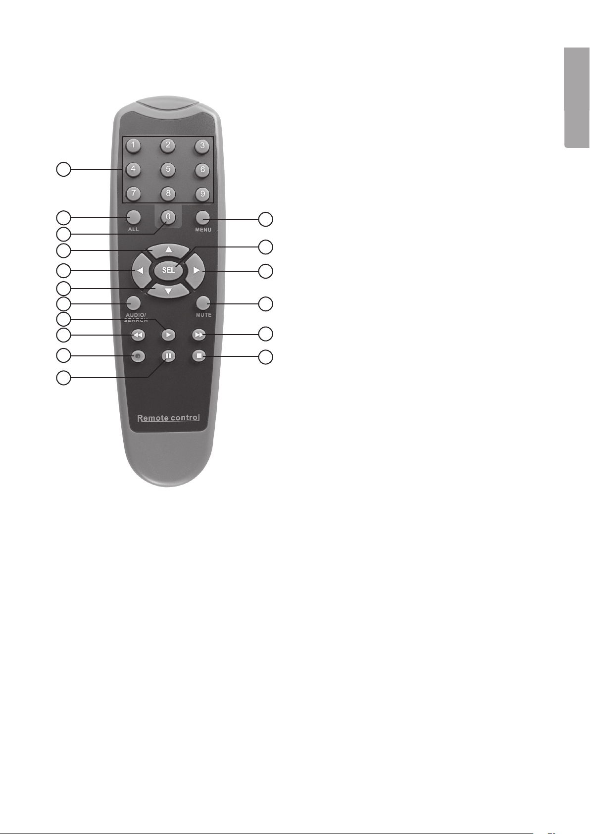
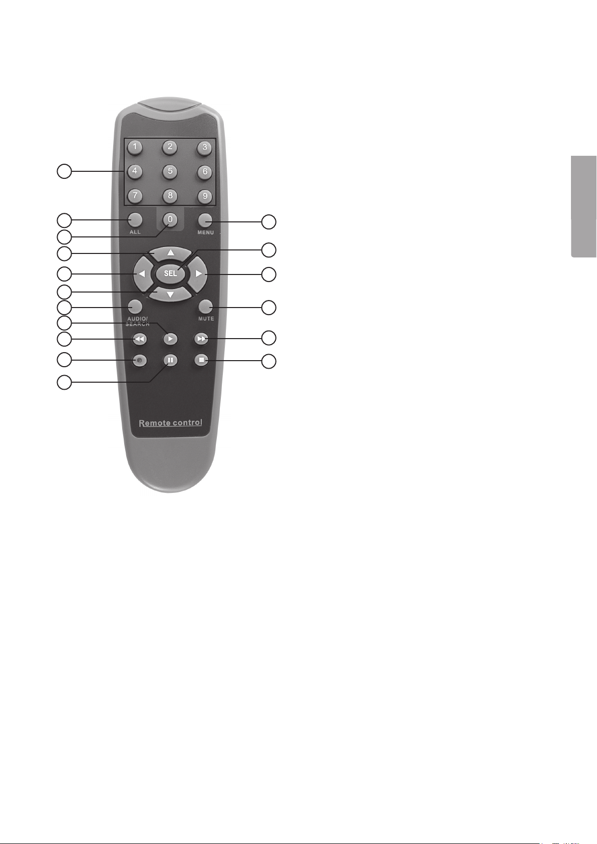
2.3 Remote Control
1. [1 – 9] Channel selection 1-9
1
2
3
4
5
6
7
8
9
10
11
12
13
14
15
16
17
2. [ALL] Displays all channels
3. [0] Number
4. [] Up arrow
5. [] Left arrow
6. [] Down arrow
7. [AUDIO/SEARCH] Audio input/output
] Starts playback
8. [
] Rewind
9. [
] Record
10. [
] Pauses playback
11. [
12. [MENU] Opens or closes the menu
13. [SEL] Selects or modifies
] Right arrow
14. [
15. [MUTE] Temporarily turns off volume
] Fast forward
16. [
] Stops recording or playback
17. [
English
2.4 Contents
• Camera with protective shade and bracket (4x)
• Power adaptor
• Power adaptor splitter cable (5 to 1)
• Extension leads (4x)
• USB cable
• Bag of screws for hard disk installation
• CD
• Keys for hard disk drawer
• Remote control
• Composite video cable BNC - RCA
5
Page 6
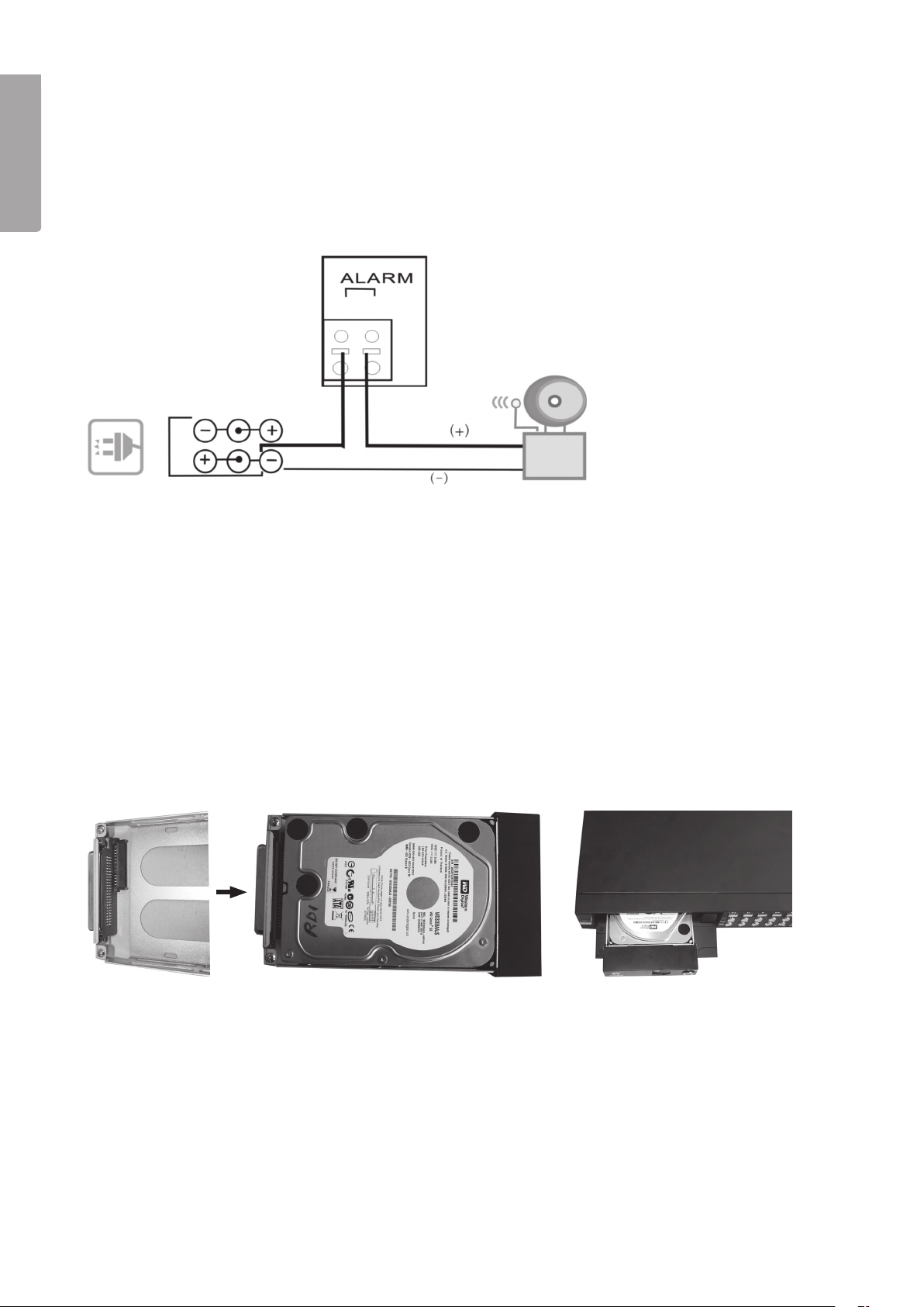
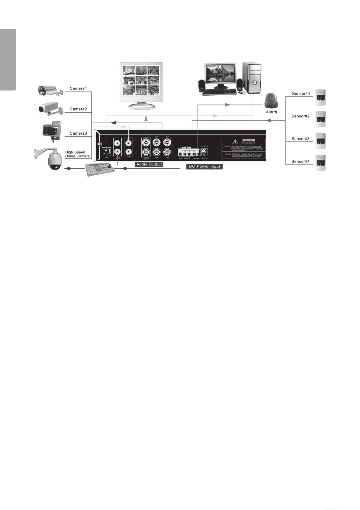
3. Alarm Installation
3.1 Alarm Installation
The video recorder has an internal circuit for sounding an alarm. This is normally open (NO), but closes once the
English
sensor is activated so that an alarm/siren (not included) sounds.
N.B. Contact a qualified tradesman for more information on an appropriate alarm and installation instructions for
purchasing an alarm that is suitable for your purposes. Two-step alarm installation:
1. Connect the positive (+) lead from the siren/alarm to the alarm port on the back panel.
2. Connect the neutral (-) lead from the siren/alarm to the power adaptor.
4. DVR system installation
4.1 Hard disk installation
N.B. Never remove the hard disk drawer when the DVR is in use. The DVR must be turned off when the hard
disk is removed otherwise the hard disk may sustain damage.
N.B. Make sure the DIP switches are set to “Master” on the hard disk before mounting. Read your hard disk
instruction manual if you are unsure.
Hard disk mounting procedure:
1. Open the front cover on the front panel (by pressing
the middle of the cover’s upper edge). Remove the hard
disk drawer.
2. Mount a SATA hard disk (Max 1 TB) into the drawer.
Secure it with the included screws.
3. Push the drawer (with the mounted
hard disk) into the opening and lock
the drawer with the drawer key.
6
Page 7

4.2 Connecting a camera to the DVR
1. Connect the extension leads between the camera and DVR. The yellow connectors are for video and the
red connectors are for the power supply to the camera.
N.B. The BNC connectors on both ends of the extension leads are marked. The side marked “To camera
side only” should be connected to the camera and the “To DVR side only” should be connected to [CH1] –
[CH4] on the back panel of the DVR.
2. Connect the splitter cable to the power adaptor.
3. Connect the cable marked “DVR POWER” to “DC 12 V” on the back panel of the DVR. Connect the rest of
the splitter connections to the red connectors on the extension leads.
4.3 Connecting the DVR to a TV
Connect the included composite video cable to the “Video Output” connection on the back panel of the DVR
and to the “Video In” connection on your TV.
5. Starting the DVR
1. The startup screen shows the date and firmware
version used.
English
2. The system will attempt to detect the hard drive. Once
detected the hard disk information will be shown.
3. Once the hard disk is detected you will be asked if you wish
to format it.
• Press [SEL] to format or [MENU] to cancel.
7
Page 8
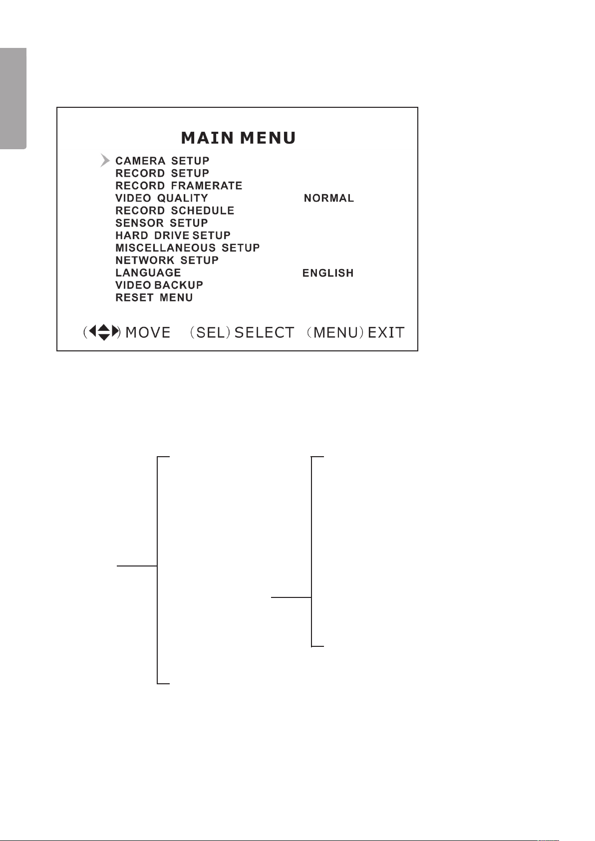
6. DVR Menus
6.1 Using the menus
English
• Push [MENU] to open the main menu.
• Use [] and [] to make your selection.
• Press [SEL] to modify or [MENU] to return to the previous screen or to cancel.
6.2 Menu structure
Change Password
Set Time
Hidden Channel
Audio Port Setup
PTZ Setup
Image Parameters
Password Enable
Keypad Tones
SEQ.DWELL TIME
VGA Setup
Main Menu
Camera Setup
Record Setup
Record Frame rate
Video Quality
Record Schedule
Sensor Setup
Hard Drive Setup
Miscellaneous Setup
Network Setup
Language
Video Backup (optional)
Reset Menu
8
Page 9
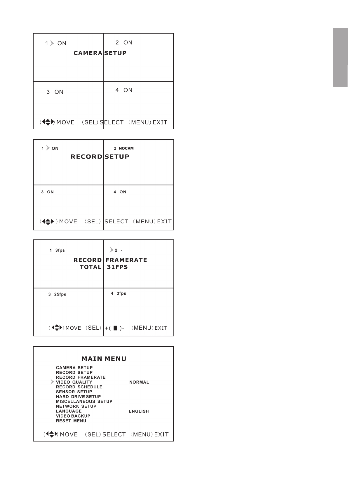
6.3 Camera Setup
Camera settings. Activate or deactivate cameras.
• Select the desired camera with [] - [] - [] -
] and then press [SEL] to switch between ON
[
and OFF modes. N.B. If the camera channel is
set to OFF, the DVR will not record from it (See
6.4 Recording settings).
6.4 Record Setup
Recording settings.
• Select the desired camera with [] - [] - [] -
] and then press [SEL] to switch between ON
[
and OFF modes. If the camera is set to OFF in
“Camera setup mode” the DVR will not record
that channel (camera) and “NOCAM” will be
displayed on the screen.
English
6.5 Record Framerate
Recording frame rate per second settings.The total
number of frames per second are 50 fps (PAL) or
60 fps (NTSC). It is possible to adjust the number
of frames per second for the selected channel
(camera). If you select a value higher than 50/60
fps the setting will automatically be adjusted to the
highest possible setting.
N.B. A higher setting will give better quality but also
take up more room on your hard disk.
• Select the desired channel (camera) with [] - []
- [] - [
value or [STOP] to reduce the value.
] and then press [SEL] to increase the
6.6 Video Quality
Video quality settings.
There are 4 different settings: Highest, High,
Normal and Low.
N.B. A higher setting will give better quality but also
take up more room on your hard disk.
• Push [SEL] to change the setting.
9
Page 10

6.7 Record Schedule
Recording schedule settings.
Scheduled recordings allow you to customise your
English
recording times.
Time is shown in AM/PM (12-hour clock)
• Select the desired time with [
[SEL] the required number of times to change the
setting between:
No-Record No recording
Normal-Record Normal recording
Sensor-Record Sensor controlled recording.
N.B. To activate recording press [
once you see the camera image on screen. If the
recording mode is set to Normal-Record recording will
start immediately. However, if the recording mode is set
to Sensor-Record recoding will not start until activated
by the motion sensor.
] - [] and press
] to start recording
6.8 Sensor Setup
Sensor settings.
Record and alarm duration settings:
• “Sensored Record Time” Selects the number
of seconds recording will progress after being
activated by the sensor. Press [SEL] to adjust the
recording time (5 – 30 seconds).
• “Alarm On Time” Selects the number of seconds
the alarm will progress after being activated by the
sensor. OFF mode (no alarm), 5 – 30 seconds,
CONT (continuous alarm. Shut off manually by
pushing any button).
6.9 H/W Sensor Setup
External sensor and alarm setup (not included).
N.B. External sensor and alarm not included. Sold
separately.
• There are 3 different settings: NOT INSTALLED,
NORMAL CLOSE (normally closed) and
NORMAL OPEN (normally open).
10
Page 11
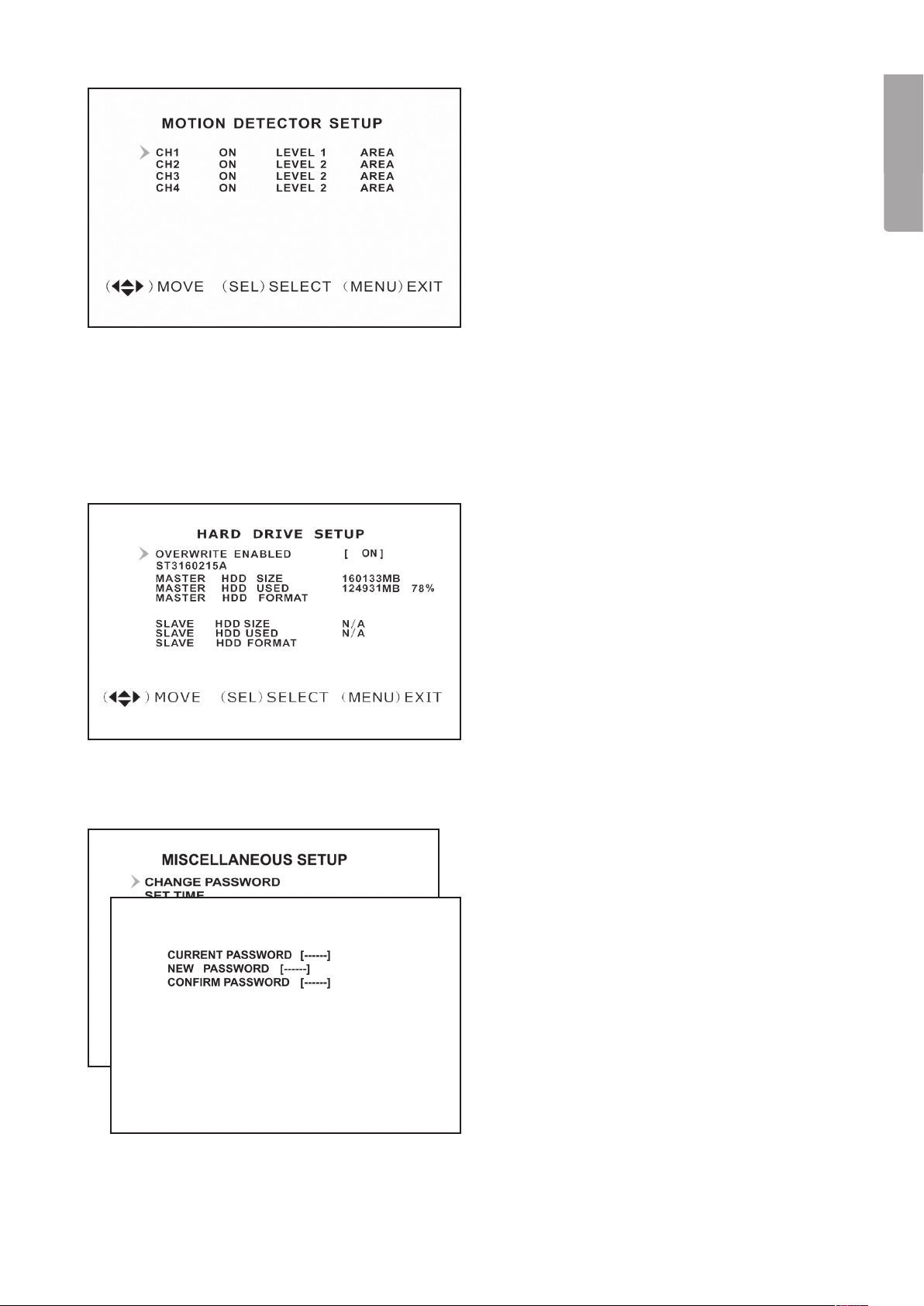
6.10 Motion Detector Setup
Motion detector settings.
It is possible to individually adjust the motion sensor
for each camera.
There are 3 different settings:
• “On/off”
• “Level” (sensitivity):
Level 1 = low
Level 2 = normal
Level 3 = high
• “Area” (selects the activation area which sets
off the motion detector). Select the area to be
detected with [] - [] - [] - [
press [SEL] to select the marked area to be
activated by the sensor. The selected sector
activates the sensor. Only the clear areas are
detectable. The shaded areas are not.
] and then
6.11 Hard Drive Setup
Hard disk settings. Displays hard disk status and
settings. Available settings:
English
• “Overwrite Enabled”
o ON (writes over the oldest files once the
hard disk is full) or
o OFF (stops recording once the hard
disk is full).
• “HDD Size” displays total hard disk capacity.
• “HDD Used” displays used hard disk space.
• “HDD Format” erases all recordings on the hard
disk. (Note! Before formating you must enter the
password 111111).
6.12 Miscellaneous Setup /
Change Password
Changing passwords.
Passwords must consist of 6 characters/symbols.
• Enter your “Current Password” first.
The preinstalled password is 111111.
• Enter a new password (consisting of 6
characters/symbols) in the “New Password” field.
• Re-enter your new password in the “Confirm
Password” field.
11
Page 12
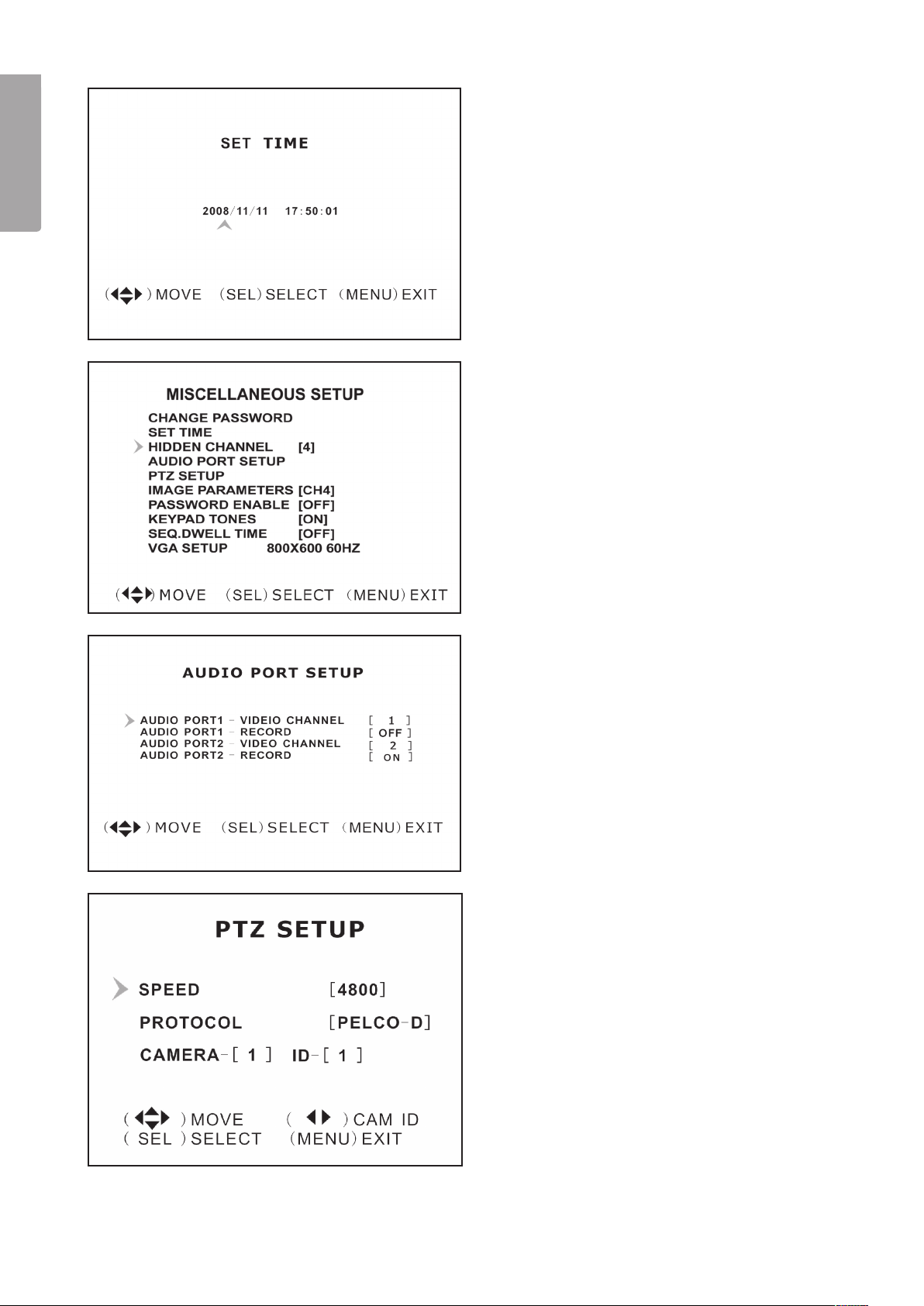
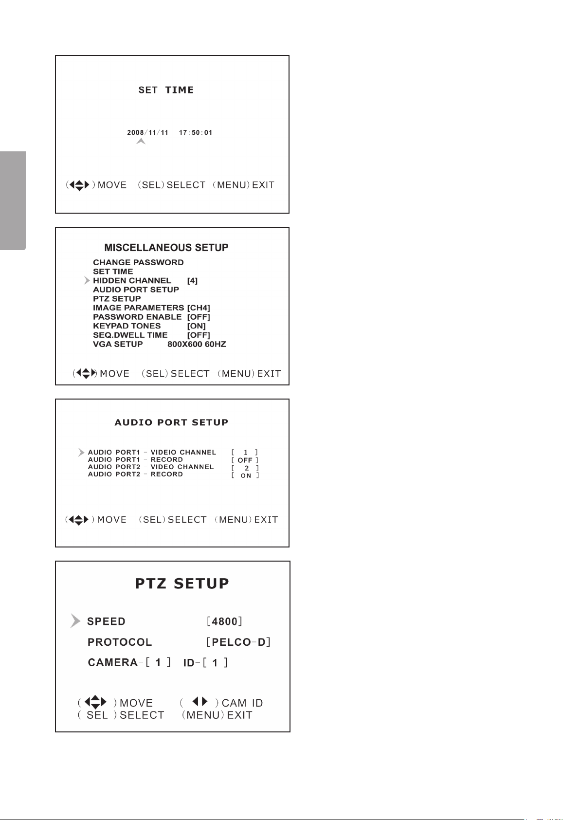
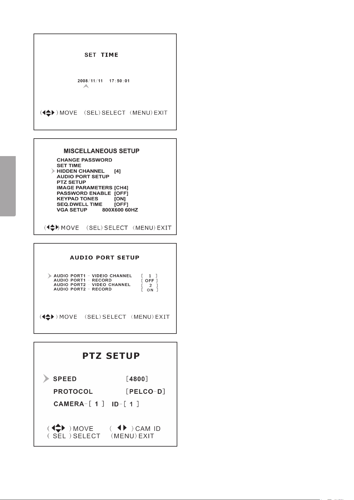
6.13 Miscellaneous Setup /
Set Time
Setting the time.
English
The time format is YYYY/MM/DD and TT:MM:SS.
• Select the desired setting with [] - [
press [SEL] to confirm the date and time settings.
Press [MENU] to save your settings and return to
the previous menu.
] and then
6.14 Miscellaneous Setup /
Hidden Channel
Hidden channel (camera) settings. It is possible to
have a hidden channel (camera) which does not
display on-screen when recording but only during
playback.
• Select a Channel 1 – 4 to hide or OFF
with [SEL].
6.15 Miscellaneous Setup /
Audio Port Setup
Audio recording settings.
• Select the desired channel (camera) for “Audio
Port 1” with [] and []. Highlight “Audio Port
1 / Record” on the row underneath. Activate
audio recording by selecting ON with [SEL] or no
recording by selecting OFF.
• Do the same for “Audio Port 2”.
6.16 Miscellaneous Setup /
PTZ Setup
Settings for automated PTZ-cameras: PAN- TILT –
ZOOM (PTZ-cameras not included).
• “Speed” Sets the desired baud rate to match
your camera speed: 4800 – 9600 – 19200 or
38400.
• “Protocol” Selects the correct protocol
PELCO-D or PELCO-P.
• “Camera” Selects the desired channel (1 to 4)
and ID (1 to 32) for your PTZ-camera. If the PTZ
camera shows full screen, press [SEL] to open
the PTZ camera menu and navigate with the [
or [] buttons.
]
12
Page 13
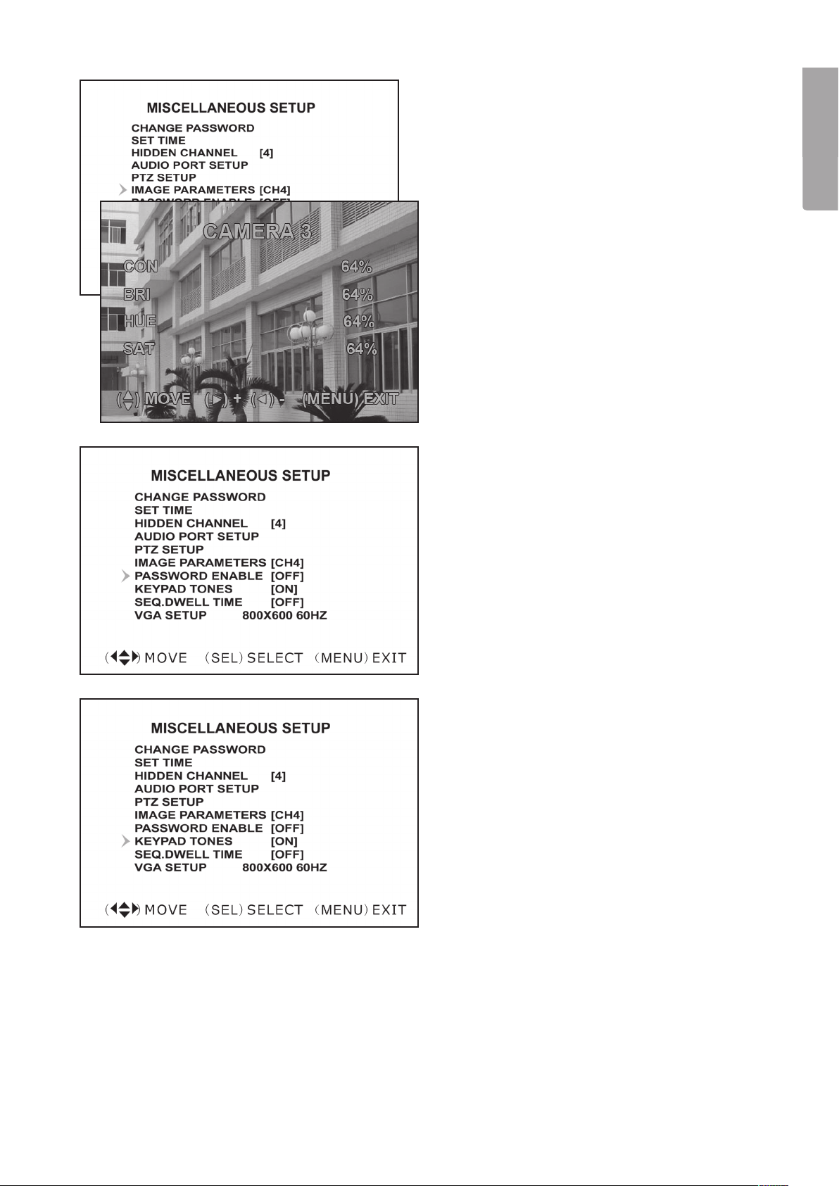
6.17 Miscellaneous Setup /
Image Parameters
Display settings.
Select the desired channel (camera) with [] - [
and press [SEL] to edit the parameters:
• “CON” Contrast
• “BRI” Brightness
• “HUE” Tint
• “SAT” Colour saturation
]
6.18 Miscellaneous Setup /
Password Enable
Enabling / disabling passwords.
• Select the desired setting with [SEL]: OFF, no
password required or ON, password required.
English
6.19 Miscellaneous Setup /
Keypad Tones
Enabling / disabling keypad tones.
• Press [SEL] to change the setting between
ON, keypad tone activated, or OFF keypad tone
inactivated.
13
Page 14
6.20 Miscellaneous Setup /
Seq.dwell
Switches monitoring between different cameras.
English
• Press [SEL] to change settings. Select between
OFF and 1 – 60 seconds.
N.B. In monitoring mode [
order to activate this feature. “SEQ” will now be
displayed on-screen.
] must be pressed in
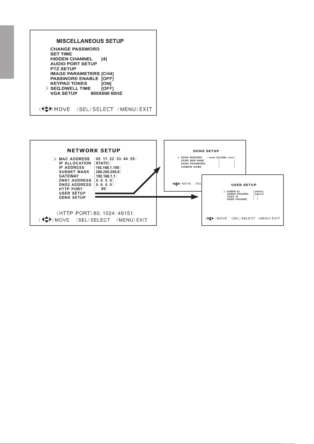
6.21 Miscellaneous Setup / Network Setup
Network settings
This feature allows you to connect the DVR to the Internet or your LAN (local area network).
• “MAC Address”
Unique hardware number.
• “IP Allocation”
Allocation of an IP address, DHCP or STATIC.
• “IP Address”
Allocated IP address.
• “Subnet Mask”
Connected to your IP address. Assists in finding your address within the network.
• “Gateway”
IP address for your modem/router.
N.B. The above can only be changed in “STATIC” mode.
• “DNS Address”
Provided by your Internet provider.
• “HTTP Port”
Port number used to communicate with the PC (normally set to Port 80).
• “User Setup”
Login and password requirments for connecting to the DVR. admin and 111111 are preset and
access the administrator account with full rights. Creates a new user account (with limited rights).
• “DDNS Setup”
Used if you require an external provider for a dynamic IP address. Enter your user information here.
14
Page 15
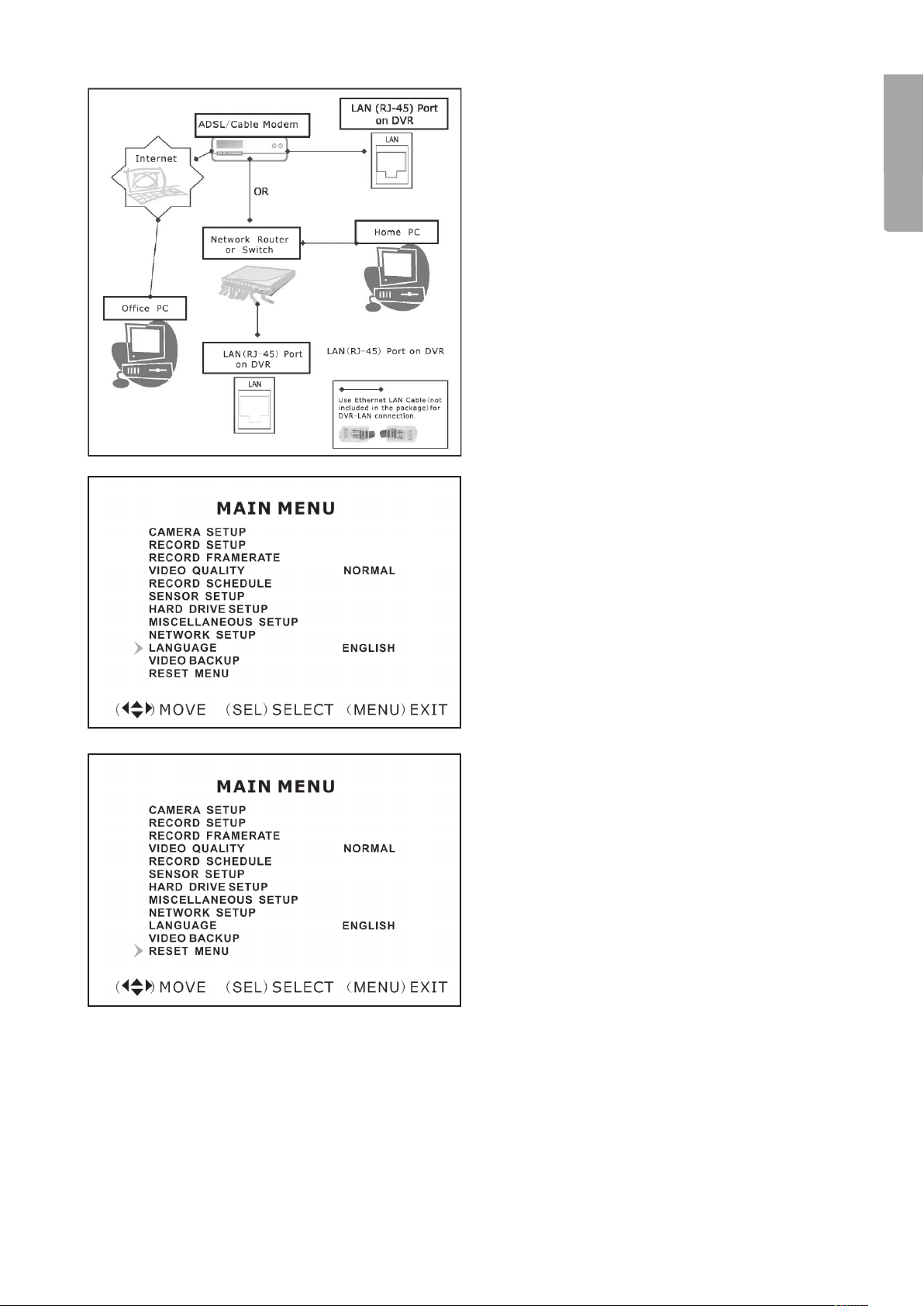
LAN-DVR connections
In order to monitor the DVR from a computer you
must have access to your LAN connection or
a broadband connection to the Internet.
(See section 9. Software installation)
6.22 Language
Menu language settings.
• Push [SEL] to change the setting between:
Italian– French – German – Portuguese –
Spanish – English
English
6.23 Reset Menu
Resets to the manufacturer’s original settings.
• Enter the password to reset to the manufacturer’s
default settings.
15
Page 16
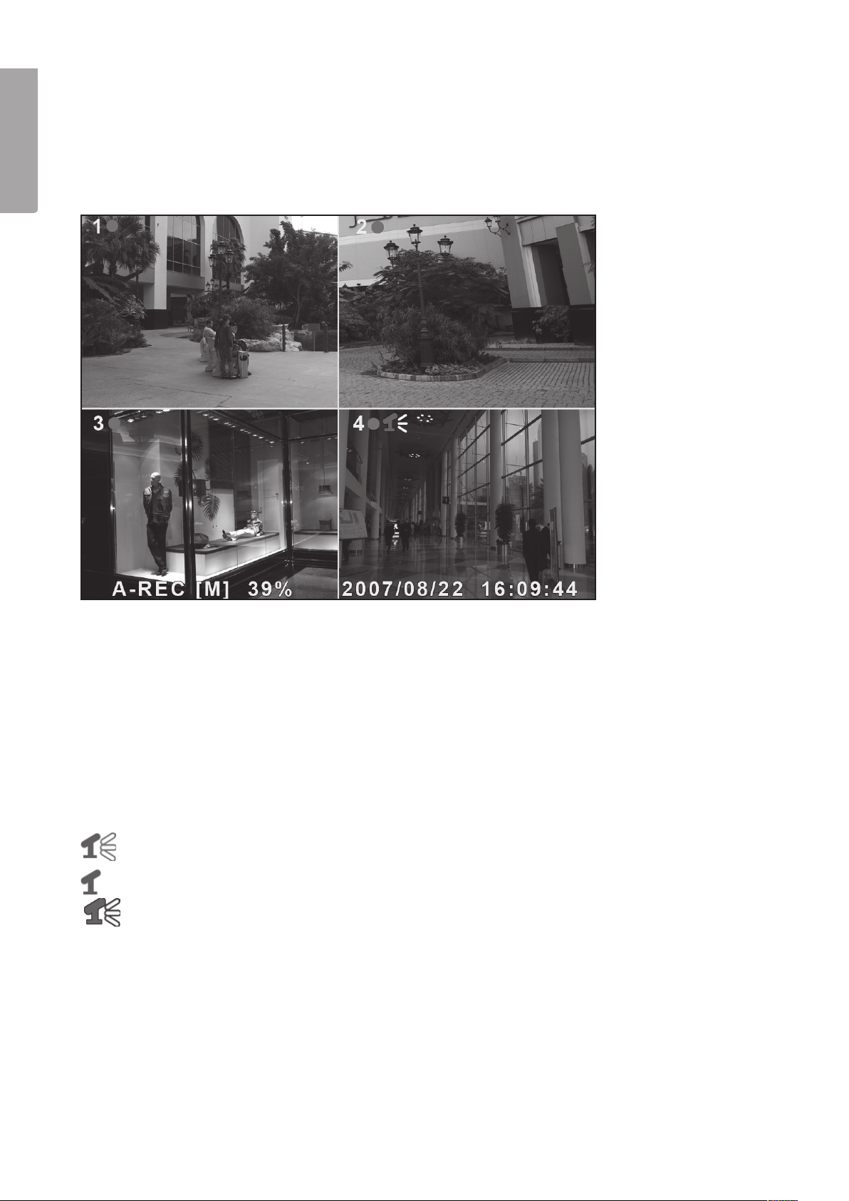
7. Record
7.1 Start recording
Press [] to start recording according to the settings set in “Record Schedule”. Recording information will be
English
shown on the screen. In the upper left hand corner of the monitored camera a red dot will be seen signalling
that the camera is recording.
Recording information:
• [A-REC] : Indicates that the scheduled recording is set to Normal-Record (continuous recording).
• [S-REC] : Indicates that the scheduled recording is set to Sensor-Record (motion sensor activated recording).
• [N-REC] : Indicates that the scheduled recording is set to No-Record (no recording).
• 39.% : Displays the percentage of used hard disk space.
• [M]: HDD info ([M] Master hard disk)
7.2 Audio recording settings
Indicates that audio on this video channel (camera) is connected to an audio port and that the audio
output is activated (ready for recording).
Indicates that the audio on this video channel (camera) is deactivated.
Indicates that the audio on this video channel (camera) is recording.
Turning off audio monitoring: Pressing [0] on the DVR turns off the audio during monitoring (audio is recorded
and is only heard during playback).
7.3 Stop recording
Pressing [] stops recording. If password access is activated you must provide the password login information
before you are able to stop the recording.
16
Page 17
7.4 Estimated recording length
Estimated recording durations (valid for 160 GB hard disks, PAL standard).
Quality 60 bps 48 bps 32 bps 16 bps 1 bps
Highest 64 89 133 267 3200
High 90 125 188 375 4500
Normal 110 153 229 458 5500
Low 123 171 256 513 6150
8. Playback
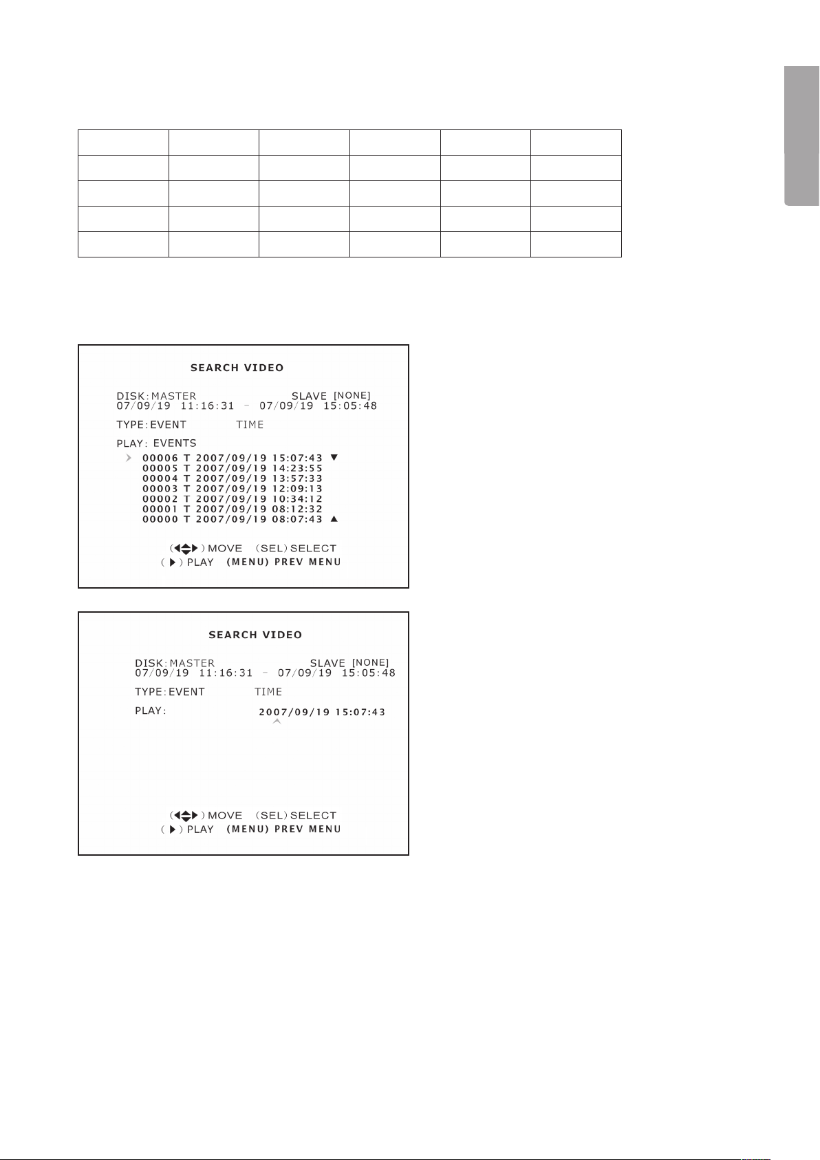
8.1 Selecting from the file list
• Press [] to reach playback mode and start
playback of the latest recording.
• Press [MENU] to open the folder where the
recorded files are located. Select EVENT
under “TYPE” to display the recorded files.
• Select the desired files for playback with
[] - [].
English
• Press [
] to start playback.
8.2 Selecting from a specifiec time
• Press [MENU] to return to “TYPE” and TIME
with [] - [] - [] - []. Press [SEL] to open
the menu.
• Select the desired recorded time period that you
wish to view with [SEL].
• Press [
• If there are no recorded events for that time
] to start playback.
period then “NO EVENTS” will be shown.
17
Page 18
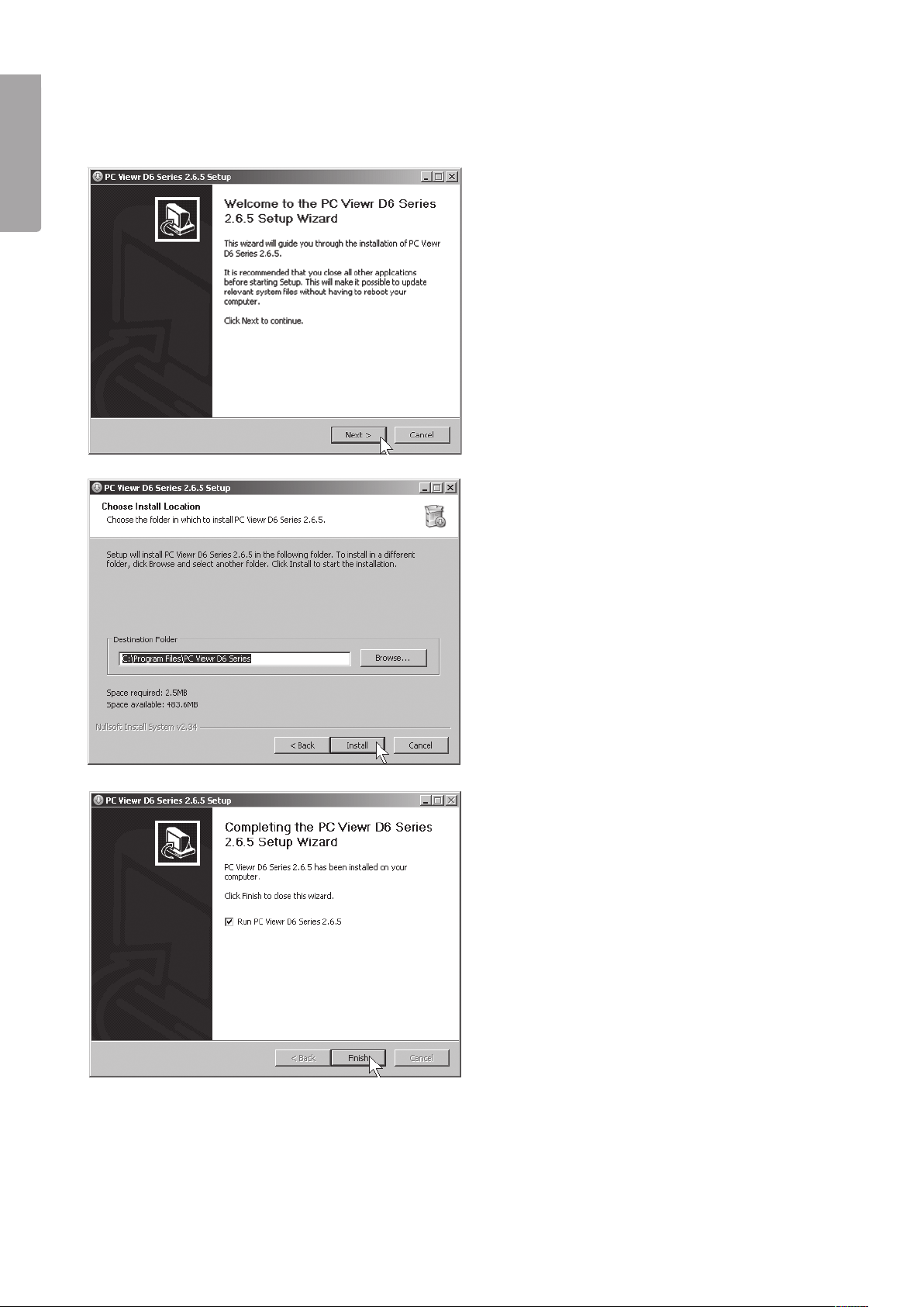
9. Installing the software
9.1 Installing the device drivers
English
1. Insert the supplied CD into the computer’s
CD-ROM.
2. Click Next to begin installation. Follow the
instructions on the screen.
3. Click Install.
4. Click Finish.
18
Page 19
10. Connecting the DVR to your computer/network
10.1 USB cable
Connect the supplied USB cable between the DVR and computer.
1. Start the PC Viewr D6 Series program. (See fig below).
2. When the program starts, previous recordings from the hard disk will be displayed.
10.2 Network cable
Connect the supplied network cable between the DVR and computer.
1. Restart the DVR after connecting the network cable.
2. Go to “Network Setup” to check the video recorder’s IP-address for DHCP: Press [MENU] on the remote and
select Network Setup. Confirm with [SEL].
3. Enter the DVR’s currently distributed IP-address and port number.
The IP address will be displayed in the “IP Address” field and the port number in the “HTTP Port” field.
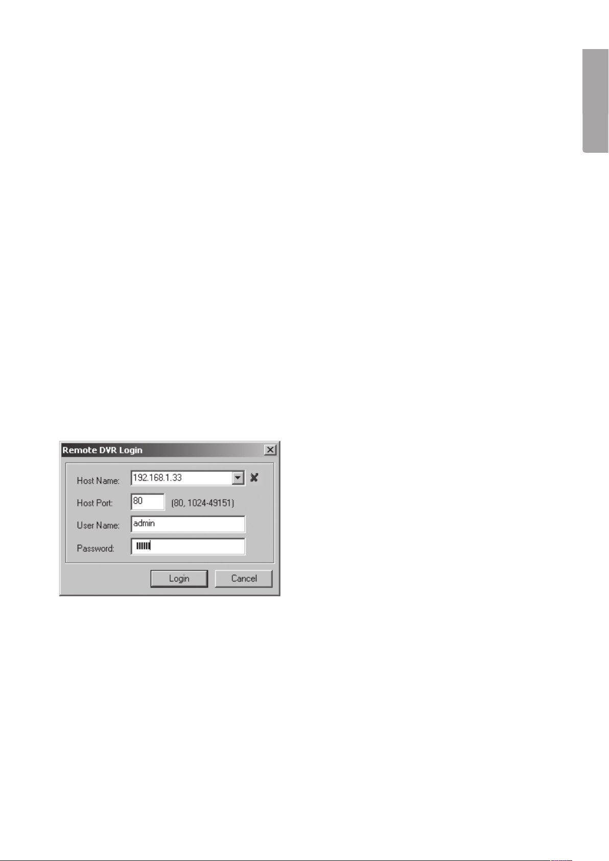
11. Configuring the new software installation
English
1. Click on the PC Viewr D6 Series icon to open the program.
2. Click [NET] (5).
3. Fill out the Log-in window:
(The picture is only an approximation of how it may actually look!)
• “Host Name” – Enter in the currently distributed IP address
• “Host Port” - 80
• “User Name” - admin
• “Password” - 111111
4. Click on Login. The camera image will now be displayed.
19
Page 20
English
10 11 12 13 14 15 16 17 18 19 20
1
2
3
4
5
6
7
8
9
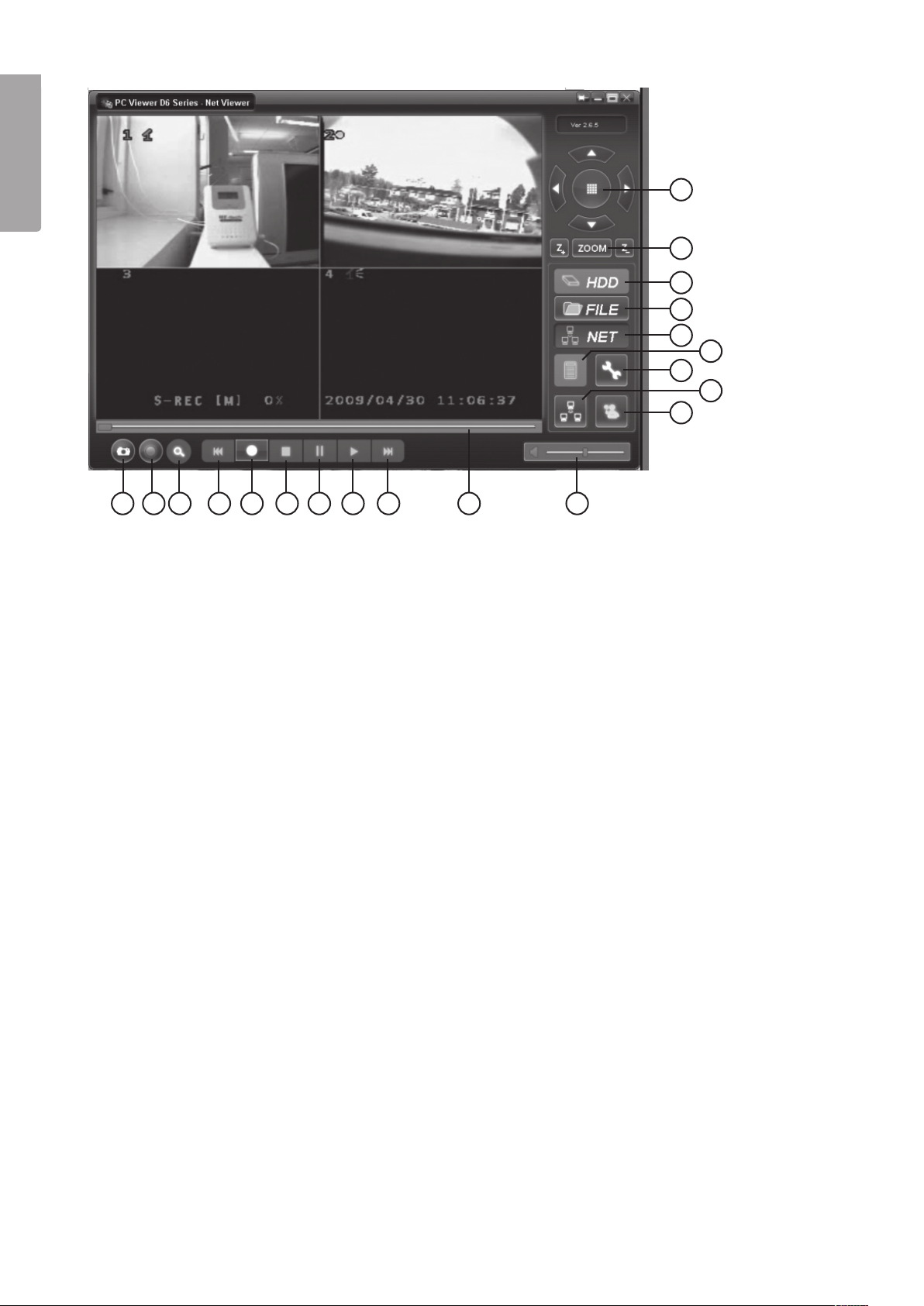
1. PTZ Control (only for any installed PTZ cameras).
2. ZOOM in, ZOOM out.
3. HDD Displays files on the hard disk.
4. FILE Opens files saved on the hard disk/USB memory etc.
5. NET Displays the current image from the DVR via the network.
6. EVENT LIST Displays previous recordings in chronological order.
7. DVR SETTING Settings for the PC Viewr program.
8. REMOTE DVR CONTROL DVR remote control settings.
9. DISCONNECT REMOTE DVR Turns off and logs out from
“Remote control settings”.
10. CAPTURE (BMP) Saves still images in bmp file format.
11. BACKUP (AVI) Back up.
12. SEARCH TIME Searches
for recordings from a specific time
period.
] Rewind.
13. [
14. [] Record.
] Stop.
15. [
] Pause.
16. [
] Play.
17. [
] Fast forward.
18. [
19. SLIDER Playback slider.
20. Volume.
12. Protecting the environment
Follow local ordinances when disposing of this product.
If you are unsure of how to dispose of this product, please contact your municipality.
20
Page 21

13. Specifications
13.1 DVR
Video standard: PAL (NTSC after resetting the components inside the DVR)
Video input/output: 4 BNC video inputs/2 BNC video outputs
Audio input/output: 2 RCA Audio outputs
Display: Resolution: 720 x 576 (PAL)
Frame rate: 100 fps (PAL)
Recording: Resolution: 720 x 288 (PAL)
Frame rate: 50 fps (PAL)
Audio: ADPCM2 CODEC
Video: MPEG4
Motion detector: Detection area and sensitivity level settings.
Microprocessor: 32-bit RISC Processor
Network interface: TCP/IP (RJ45)
Hard disk interface: SATA, max. 1 TB
PTZ interface: RS485
USB interface: USB 2.0
English
Remote control: Yes, IR
13.2 Camera
Min. lighting: 0 Lux (12-IR at CDS auto)
Vertical frequency: 50 Hz (PAL)
Resolution (horisontal): 420 TV lines
LED wavelength: 850 nm
IR range: 8 metres (12 LEDs)
IR activation: CDS-automatic
Lens: f3.6 F2.0/f6.0 F2.0
Electronic shutter: 1/50 – 1/100000 second
SNR: ≥ 48 dB
Gamma correction: 0.45
Video output: 1.0 Vp-p / 75 Ω, BNC
Size/weight: Ø 60 mm x 100 mm / 260 g
21
Page 22
14. Connections
English
22
Page 23

Digital Videoinspelare DVR
Art.nr 36-3777 Modell D6004CK
Läs igenom hela bruksanvisningen före användning och spara den sedan för framtida bruk. Vi reserverar oss
för ev. text- och bildfel samt ändringar av tekniska data. Vid tekniska problem eller andra frågor, kontakta vår
kundtjänst (se adressuppgifter på baksidan).
1. Beskrivning
• MPEG4 kompression
• 4-Kanaler: 4 BNC kameraingångar – 2 BNC Videoutgångar.
• Systemformat: NTSC/PAL.
• Rörelsedetektor med inställning för yta och känslighet.
• Schemalagd inspelningstid, Alarm eller rörelseaktiverade inspelningslägen.
• Stöd för hårddisk upp till 1TB (SATA).
• Stöder PTZ-kontroll via Port 485.
• Övervaka och styr utrustningen via nätet (bredbandsanslutning erfordras).
• Inbyggd USB 2.0-port för backupp till dator eller ett USB-minne.
Svenska
1.1 Säkerhet
• Videoinspelaren är endast avsedd för inomhusbruk, utsätt den inte för fukt.
• Använd endast den bifogade nätadaptern (12 V, 5 A med plus i centrum).
• Kamerorna är vattentäta, men de bör ändå monteras så skyddat som möjligt.
• Tänk på att kabelskarvarna vid kamerorna måste skyddas mot inträngande fukt,
de är ej skyddade mot fukt och väta.
23
Page 24
2. Knappar och funktioner
2.1 Framsida 4 kanals DVR
1
Svenska
SVENSK A
1. Strömbrytare
2. Hårddisklås
3. PWR Lysdiod (Power lampa)
] Spola bakåt
4. [
5. [1
6. [
7. [2
8. [
9. [3
10. [
11. [4
12. [
13. [
] Kanal 1
] Paus
] Kanal 2
] Uppspelning
] Kanal 3
] Snabbspolning framåt
] Kanal 4
] Stopp
] Inspelning
2 8 10 12
19 20
4 156 13
3
5 7
PWR 1 2 3 4 5 6
HDD
7 8 9 0 ALL MENU
14. [5-9] Nummer 5 till Nummer 9
15. IR-sensor
] Pil Vänster
16. [
] Pil Uppåt
17. [
] Pil Höger
18. [
19. Hållare för hårddisk och USB-anslutning
(Innanför luckan)
20. HDD Lysdiod
21. [0] Stäng av ljudet tillfälligt (Mute)
22. [
23. [MENU] Gå ur meny
24. [
25. [SEL] Välj (Select)
] Visa alla kameror
] Pil Neråt
9 11 14 16 18
21 22 23 24
17
SEL
25
2.2 Baksida 4 kanals DVR
1 2 3 4 5 6 7
1. LAN - Anslutning för nätverkskabel
2. Audio Output - Ljudutgång
3. Audio Input – Ljudingång
4. Video Output – Videoutgång (BNC)
5. CH1 – CH 4 - Videoingång (BNC)
6. RS485 (PTZ-ingång)
7. DC 12 V – Anslutning för nätadapter
24
Page 25
2.3 Fjärrkontroll
1
2
3
4
5
6
7
8
9
10
12
13
14
15
16
17
1. [1 – 9] Kanalval 1-9
2. [ALL] Visa alla kanaler
3. [0] Nummer
] Pil Uppåt
4. [
] Pil Vänster
5. [
] Pil Neråt
6. [
7. [AUDIO/SEARCH] Audio ingång/utgång
] Starta uppspelning
8. [
] Spola bakåt
9. [
] Inspelning
10. [
] Gör paus i uppspelning
11. [
12. [MENU] Öppna eller stäng meny
13. [SEL] Välj eller modifiera
] Pil Höger
14. [
15. [MUTE] Stäng av ljudet tillfälligt
] Snabbspolning framåt
16. [
Svenska
11
2.4 Förpackningen innehåller
• Kamera med skyddskåpa och fäste (4 x)
• Nätadapter
• Förgreningskabel till nätadapter (5 till 1)
• Skarvkabel (4 x)
• USB-kabel
• Påse med skruv till hårddisk
• CD-skiva
] Stoppa inspelning eller uppspelning
17. [
• Nycklar till hårddiskhållare
• Fjärrkontroll
• Kompositvideokabel BNC - RCA
25
Page 26

3. Installation av alarm
3.1 Installation av alarm
Videoinspelaren har en intern funktion för alarmljud. Den är normalt öppen (NO), men sluter när sensorn
aktiveras så att en alarmsummer/sirén (ingår ej) ljuder.
Obs! Kontakta en kvalificerad yrkesman för att få information om lämpligt alarm och installation för ditt behov.
Alarminstallationen har två steg:
Svenska
SVENSK A
1. Anslut pluskabeln (+) från sirén/summer till alarmanslutningen på baksidan.
2. Anslut minuskabeln (-) från sirén/summer till nätadapter.
4. DVR Systeminstallation
4.1 Installera en hårddisk
Obs! Ta aldrig ur hårddiskhållaren när videoinspelaren används. DVR måste vara avstängd när hårddiskhållaren
dras ut, annars kan hårddisken ta skada.
Obs! Kontrollera att hårddisken är byglad som ”Master” innan du monterar den i hårddiskhållaren, läs
bruksanvisningen för hårddisken om du är osäker.
Montera hårddisken så här:
1. Öppna luckan på framsidan (tryck in mitten på luckans
överkant). Dra ut hårddiskhållaren.
2. Montera en SATA-hårddisk (Max 1 TB) i hårddiskhållaren, skruva
fast hårddisken med de medföljande skruvarna.
3. Tryck in hårddiskhållaren (med
hårddisk) i öppningen, lås fast
hållaren med nyckeln.
26
Page 27

4.2 Anslut kamera till videoinspelaren
1. Anslut skarvkablarna mellan kamera och videoinspelare. De gula kontakterna är videosignal och de röda
kontakterna är strömförsörjning till kamera.
Obs! Skarvkablarna har märkning i bägge ändar vid BNC-kontakten, ”To camera side only” skall anslutas
till kameran och den andra änden ”To DVR side only” skall anslutas till [CH1] – [CH4] på baksidan av
videoinspelaren.
2. Anslut förgreningskabeln till nätadaptern.
3. Anslut den del av förgreningskabeln som är märkt ”DVR POWER” till ”DC 12 V” på baksidan av videoinspelaren. Anslut de övriga ändarna av förgreningskabeln till de röda kontakterna på skarvkablarna.
4.3 Anslut videoinspelare till en TV
Anslut den bifogade kompositvideokabeln till ”Video Output” på baksidan av DVR och till ”Video In” på en TV.
5. Starta DVR
1. Startbilden visar datum och version för den
firmware som används.
2. Hårddisken hittas och information om den visas.
Svenska
3. När hårddisken hittas första gången kommer du att bli
tillfrågad om du vill formatera hårddisken.
• Tryck på [SEL] för att formatera eller på [MENU] för att
avbryta.
27
Page 28

6. DVR Menyer
6.1 Använd menyerna
Svenska
SVENSK A
• Tryck på [MENU] för att öppna huvudmenyn.
• Använd [
• Tryck på [SEL] för att ändra eller [MENU] för att återgå till föregående eller avbryta.
] och [] för att välja i aktuell meny.
6.2 Menyernas uppbyggnad
Change Password
Set Time
Hidden Channel
Audio Port Setup
PTZ Setup
Image Parameters
Password Enable
Keypad Tones
SEQ.DWELL TIME
VGA Setup
Main Menu
Camera Setup
Record Setup
Record Frame rate
Video Quality
Record Schedule
Sensor Setup
Hard Drive Setup
Miscellaneous Setup
Network Setup
Language
Video Backup (optional)
Reset Menu
28
Page 29

6.3 Camera setup
Kamerainställning, aktivera eller stänga av kameror.
• Välj önskad kamera med [
och tryck sedan [SEL] för att växla mellan ON
och OFF. Obs! Om en kamerakanal är inställd
på OFF kommer inte DVR att spela in (Se 6.4
Inställning för inspelning).
] - [] - [] - []
6.4 Record setup
Inställning för inspelning.
• Välj önskad kamera med [
och tryck sedan [SEL] för att växla mellan
ON och OFF. Om en kamera är avstängd
i ”Kamerainställning” kommer inte DVR att spela
in den kanalen (kameran) och displayen visar
”NOCAM”.
] - [] - [] - []
Svenska
6.5 Record framerate
Inställning för bilder per sekund.
Det totala antalet bilder per sekund är 50 bps (PAL)
eller 60 bps (NTSC). Det går att ställa in bilder per
sekund för den valda kanalen (kameran). Väljer
du ett värde som är högre än 50/60 bps justeras
inställningen till den högsta möjliga.
Obs! Högre inställt värde ger bättre bilder men tar
mera plats på hårddisken.
• Välj önskad kanal (kamera) med [
[] och tryck sedan [SEL] för att öka värdet eller
på [STOP] för att minska värdet.
] - [] - [] -
6.6 Video quality
Inställning för videokvalitet.
Det finns 4 olika inställningar: Highest (högsta), High
(hög), Normal (normal) och Low (låg).
Obs! Högre inställt värde ger bättre bilder men tar
mera plats på hårddisken.
• Tryck på [SEL] för att ändra inställning.
29
Page 30

6.7 Record schedule
Inställningar för schemalagd inspelning.
Schemalagd inspelning gör det möjligt till egna in-
ställningar för inspelning. Tidsformatet visas som
AM/PM (12-timmarsvisning).
• Välj önskad timme med [
sedan [SEL] upprepade gånger för att ändra
inställning mellan:
No-Record Ingen inspelning
Normal-Record Kontinuerlig inspelning
Sensor-Record Sensor-styrd inspelning
Svenska
SVENSK A
Obs! Aktivera inspelning så här: Tryck in [
att starta inspelning när kamerans bild visas på
skärmen. Om inspelningen är inställd på Normal-
Record startar inspelningen direkt. Om inställningen
är Sensor-Record startar inspelningen när kameran
aktiveras av rörelsesensorn.
] - [] och tryck
] för
6.8 Sensor setup
Inställningar för sensor.
Inställningar bl.a. för tiden som inspelningen pågår
efter aktivering av sensorn, om en summer ska ljuda
när sensorn aktiveras.
• ”Sensored record time” Välj hur många sekunder
som inspelningen skall pågå efter aktivering av
sensorn. Tryck på [SEL] för att ändra inställning
(5 – 30 sekunder).
• ”Alarm on time” Välj hur många sekunder som
summern skall ljuda när sensorn har aktiverats.
OFF (Inget alarm), 5 – 30 sekunder, CONT
(kontinuerligt tills du trycker på någon av
knapparna).
6.9 H/W sensor setup
Inställningar för yttre sensor och alarm.
Obs! Yttre sensor och alarm ingår ej utan måste kö-
pas separat.
• Det finns 3 olika sensorinställningar: NOT
INSTALLED (ej installerad), NORMAL CLOSE
(normalt sluten) och NORMAL OPEN (normalt
öppen).
30
Page 31

6.10 Motion detector setup
Inställningar för rörelsesensor.
Möjlighet att justera rörelsedetektorn för varje kamera.
Det finns 3 olika inställningar för rörelsedetektor:
• ”On/off” (av/på).
• ”Level” (känslighet):
Level 1 = låg
Level 2 = normal
Level 3 = högsta känslighet
• ”Area” (välj bildområde som aktiverar
rörelsedetektor). Välj önskat bildsegment
] - [] - [] - [] och tryck sedan
med [
[SEL] för att välja den markerade ytan för att
styra rörelsedetektorn. Den valda bildytan styr
detektorn om rörelse detekteras i den markerade
sektorn. Detta fungerar när den är belyst men
inte om den ligger i skugga.
6.11 Hard drive setup
Inställningar för hårddisk.
Svenska
Visar inställningar och status för hårddisken.
Inställningar för hårddisken:
• ”Overwrite enabled”
o ON (skriver över de äldsta filerna när
hårddisken är full) eller
o OFF (stoppa inspelning när hårddisken är full).
• ”HDD size” visar total hårddiskkapacitet.
• ”HDD used” visar hur mycket av kapaciteten
är utnyttjad.
• ”HDD format” raderar alla inspelningar på
hårddisken. Obs! Vid formatering måste du ange
lösenordet 111111.
6.12 Miscellaneous setup /
Change password
Byte av lösenord.
Lösenordet måste bestå av 6 tecken.
• Skriv in det gamla lösenordet ”Current Password”
först, det fabriksinställda är 111111.
• Skriv in det nya lösenordet vid ”New Password”.
• Skriv in det igen vid ”Confirm Password”.
31
Page 32
6.13 Miscellaneous setup /
Set time
Inställning av tid.
Tidsformatet är ÅÅÅÅ/MM/DD och TT:MM:SS.
• Välj önskad inställning med [
sedan på [SEL] för att ställa in kalender och tid.
Tryck på [MENU] för att spara inställning och
återgå till föregående meny.
Svenska
SVENSK A
] - [] och tryck
6.14 Miscellaneous setup /
Hidden channel
Inställning för dold kanal (kamera). Det finns
möjlighet att ha en kanal (kamera) dold så att den
inte visas på skärmen under inspelning, bilderna
visas endast vid uppspelning.
• Välj Channel 1 – 4 eller OFF (avstängd)
med [SEL].
6.15 Miscellaneous setup /
Audio port setup
Inställning för ljudinspelning.
• Välj önskad kanal (kamera) för ”Audio port 1”
] och [], markera ”Audio port 1 /
med [
Record” på raden under, aktivera inspelning av
ljud genom att välja ON med [SEL] eller stäng av
ljudinspelning genom att välja OFF.
• Gör lika för ”Audio port 2”.
6.16 Miscellaneous setup /
PTZ setup
Inställningar för motorstyrda PTZ-kameror:
PAN – TILT – ZOOM (PTZ-kamera ingår ej).
• ”Speed”: Ställ in önskad hastighet (baud rate):
4800 – 9600 – 19200 eller 38400.
• ”Protocol”: Välj rätt protocol PELCO-D eller
PELCO-P.
• ”Camera” Välj önskad kanal (1 till 4) och ID
(1 till 32) för PTZ-kameran.
Om PTZ-kamerans bild visas som helbild, tryck
då på [SEL] för att öppna PTZ-kamerans meny.
Navigera i menyn med [
] eller [].
32
Page 33

6.17 Miscellaneous setup /
Image parameters
Inställning för bildvisning.
Välj önskad kanal (kamera) med [
sedan på [SEL] för öppna inställningarna:
• ”CON” Kontrast
• ”BRI” Ljus
• ”HUE” Färg
• ”SAT” Intensitet
] - [] och tryck
6.18 Miscellaneous setup /
Password enable
Aktivera / stäng av lösenord.
• Välj önskad funktion med [SEL]: OFF avstängd,
lösenord krävs ej eller ON lösenord krävs.
Svenska
6.19 Miscellaneous setup /
Keypad tones
Aktivera / stäng av knappljud.
Tryck på [SEL] för ändra inställningarna mellan:
• ON Aktivering av knappljud.
• OFF Inga ljud när knapparna trycks in.
33
Page 34

6.20 Miscellaneous setup /
Seq.Dwell time
Växling mellan visning från olika kameror.
• Tryck på [SEL] för ändra inställningarna, växla
mellan OFF (avstängd) och 1 – 60 sekunder.
Obs! I visningsläge för kameror måste [
först för att aktivera denna funktion. ”SEQ” visas nu
på skärmen.
Svenska
SVENSK A
] tryckas in
6.21 Miscellaneous setup / Network setup
Inställningar för nätverket
Denna funktion låter dig ansluta videoinspelaren till Internet eller till ett lokalt nät.
• ”MAC address”
Unikt hårdvarunummer.
• ”IP allocation”
Tilldelning av IP-nummer, DHCP eller STATIC (statiskt).
• ”IP address”
Tilldelat IP-nummer.
• ”Subnet mask”
Kopplat till IP-nummer för att hitta nätverket.
• ”Gateway”
IP-nummer till modem/router.
Obs! Ovanstående kan endast ändras i läge STATIC.
• ”DNS address”
Erhålls av din internetleverantör.
• ”HTTP port”
Portnummer som används vid kommunikation med PC (normal inställning är Port 80).
• ”User setup”
Login och lösenord för att ansluta till videoinspelaren. Admin resp. 111111 är förinställt för båda med
administratörsrättigheter. Skapa ett till användarkonto (med begränsade rättigheter).
• ”DDNS setup”
Om du behöver en extern service för att få en dynamisk IP-address, måste du skriva in
användarinformation här.
34
Page 35

LAN-DVR-anslutning
För att övervaka videoinspelaren från en dator
måste du ha tillgång till en LAN-anslutning eller
en bredbandsanslutning till Internet.
(Se 9. Installera programvara)
6.22 Language
Inställningar för menyspråk.
• Tryck på [SEL] för ändra inställningarna mellan:
Italienska – Franska – Tyska – Portugisiska –
Spanska – Engelska.
Svenska
6.23 Reset menu
Återställning till fabriksinställningarna.
• Skriv in lösenordet för att återställa
till fabriksinställningarna.
35
Page 36

7. Inspelning
7.1 Starta inspelning
Tryck på [] för att starta inspelningen enligt inställningarna i ”Record Schedule”. Information om inspelningen
visas på skärmen, i övre vänstra hörnet på kamerans bild visas en röd cirkel när inspelning pågår.
Svenska
SVENSK A
Bildinformation:
• [A-REC] : Visar att den schemalagda inspelningen är inställd på Normal-Record (kontinuerlig inspelning).
• [S-REC] : Visar att den schemalagda inspelningen är inställd på Sensor-Record (sensorstyrd inspelning).
• [N-REC] : Visar att den schemalagda inspelningen är inställd på No-Record (ingen inspelning).
• 39% : Visar hur stor del av hårddiskens kapacitet som är använd.
• [M]: HDD info ([M] Master hårddisk)
7.2 Inspelning av ljud
Visar att ljudet på denna videokanal (kamera) är kopplat till en audio-port och ljudutgången
är aktiverad (redo att spelas in).
Visar att ljudet på denna videokanal (kamera) är avstängt.
Visar att ljudet på denna videokanal (kamera) spelas in (röd symbol).
Stäng av ljudet så här vid behov: Tryck på [0] på videoinspelaren för att stänga av
(ljudet spelas in, och hörs endast vid uppspelning).
7.3 Stoppa inspelning
Tryck på []. Om lösenordsinloggning är aktiverad måste du ange lösenordet innan inspelningen kan stoppas.
36
Page 37

7.4 Ungefärlig inspelningstid
Ungefärlig inspelningstid i timmar (gäller för 160 GB hårddisk, PAL standard).
Kvalitet 60 bps 48 bps 32 bps 16 bps 1 bps
Högsta 64 89 133 267 3200
Hög 90 125 188 375 4500
Normal 110 153 229 458 5500
Låg 123 171 256 513 6150
8. Uppspelning
8.1 Välj inspelning från fillistan
• Tryck på [] för att öppna uppspelningsläge och
starta uppspelning av den senaste inspelningen.
• Tryck på [MENU] för att öppna mappen där de
inspelade filerna finns. Välj EVENT vid ”Type” för
att visa inspelade filer.
• Välj önskad fil för uppspelning med [
• Tryck på [
] för att starta uppspelning.
] - [].
8.2 Välj inspelning från en viss tid
• Eller tryck på [MENU] för att stega upp till ”Type”
och TIME med [] - [] - [] - []. Tryck på
[SEL] för att öppna menyn.
• Välj önskad tid där du vill kontrollera inspelning
med [SEL].
Svenska
• Tryck på [
• Om det inte finns någon inspelning från den valda
tiden, visas ”NO EVENTS”.
] för att starta uppspelning.
37
Page 38

9. Installera programvara
9.1 Installera drivrutiner
1. Sätt i den bifogade CD-skivan i datorns CD-läsare.
2. Klicka på Next för att börja installationen.
Följ instruktionerna på skärmen.
Svenska
SVENSK A
3. Klicka på Install.
4. Klicka på Finish.
38
Page 39

10. Koppla videoinspelaren till dator/nätverk
10.1 Via USB-kabel
Anslut den bifogade USB-kabeln mellan videoinspelaren och en dator.
1. Starta programmet PC Viewr D6 Series. (Se bild nedan).
2. När programmet startar visas tidigare inspelningar på hårddisken.
10.2 Via nätverkskabel
Anslut den bifogade nätverkskabeln mellan videoinspelaren och en dator.
1. Starta om videoinspelaren efter att nätverkskabeln är isatt.
2. Gå in i ”Network setup” för att se videoinspelarens IP-adress för DHCP:
Tryck på [MENU] på fjärrkontrollen och välj sedan Network Setup, bekräfta med [SEL].
3. Skriv ner videoinspelarens tilldelade IP-adress samt portnummer. IP-adressen visas i fältet ”IP-address”
och portens nummer i fältet ”HTTP port”.
11. Konfigurering av den installerade programvaran
1. Klicka på ikonen PC Viewr D6 Series för att öppna programmet.
2. Klicka på knappen [NET] (5).
3. Fyll i inloggningsrutan:
(Bilden är endast ett exempel hur det kan se ut!)
Svenska
• ”Host Name” - Skriv in den tilldelade IP-addressen
• ”Host Port” - 80
• ”User Name” - admin
• ”Password” - 111111
4. Klicka på LOGIN, nu visas bild från kamera.
39
Page 40

1
2
3
4
5
Svenska
SVENSK A
10 11 12 13 14 15 16 17 18 19 20
6
7
8
9
1. PTZ Control (endast för installerad PTZ-kamera).
2. ZOOM in, ZOOM out.
3. HDD Visa filer på hårddisken.
4. FILE Öppna filer som är sparade på t.ex.
Hårddisk/USB-minne.
5. NET Visa aktuell bild från videoinspelaren via nätverket.
6. EVENT LIST Lista på inspelningar i kronologisk ordning.
7. DVR SETTING Inställningar för programmet PC Viewr.
8. DISCONNECT REMOTE DVR Stäng av och logga ut från
”Fjärrinställningar”.
9. REMOTE DVR CONTROL Fjärrinställningar till DVR.
10. CAPTURE (BMP) Spara som stillbild i bmp-format.
11. BACKUPP (AVI) Backupp.
12. SEARCH TIME Sök efter inspelningar
från viss tid.
] Snabbspolning bakåt.
13. [
] Starta inspelning.
14. [
] Stopp.
15. [
] Paus.
16. [
] Uppspelning.
17. [
] Snabbspolning framåt.
18. [
19. SLIDER Dra till viss del av filen.
20. Volym.
12. Skydda miljön
När du ska göra dig av med produkten ska detta ske enligt lokala föreskrifter.
Är du osäker på hur du ska gå tillväga, kontakta din kommun.
40
Page 41

13. Specifikationer
13.1 Videoinspelare
Videostandard: PAL (NTSC efter omställning inuti DVR)
Videoingång/utgång: 4 BNC Videoingångar/2 BNC Videoutgångar
Audioingång/utgång: 2 RCA Audioutgångar
Visning: Upplösning: 720 x 576 (PAL)
Bildhastighet: 100 bps (PAL)
Inspelning: Upplösning: 720 x 288 (PAL)
Bildhastighet: 50 bps (PAL)
Audio: ADPCM2 CODEC
Video: MPEG4
Rörelsedetektor: Inställbart område och känslighet
Mikroprocessor: 32 bitars RISC Processor
Nätverksgränssnitt: TCP/IP (RJ45)
Hårddisk, gränssnitt: SATA, max. 1 TB
PTZ gränssnitt: RS485
USB gränssnitt: USB 2.0
Svenska
Fjärrkontroll: Ja, IR
13.2 Kamera
Min. belysning: 0 Lux (12-IR på CDS auto)
Vertikal frekvens: 50 Hz (PAL)
Upplösning (horisontell): 420 TV-linjer
Våglängd för LED: 850 nm
IR-räckvidd: 8 meter (12 LED)
IR aktivering: CDS-automatik
Lins: f3.6 F2.0 / f6.0 F2.0
Elektronisk slutare: 1/50 – 1/100 000 sekund
S/N, störavstånd: ≥ 48 dB
Gammakorrektion: 0,45
Videoutgång: 1,0 Vp-p / 75 Ω, BNC
Storlek/vikt: Ø 60 mm x 100 mm / 260 g
41
Page 42

14. Inkoppling
Svenska
SVENSK A
42
Page 43

Digital Videospiller DVR
Art.nr. 36-3777 Modell D6004CK
Les nøye igjennom hele bruksanvisningen og ta vare på den til senere bruk. Vi reserverer oss mot ev. tekst- og
bildefeil, samt forandringer av tekniske data. Ved tekniske problemer eller andre spørsmål, ta kontakt med vårt
kundesenter (se opplysninger på baksiden).
1. Beskrivelse
• MPEG4 kompresjon
• 4-Kanaler: 4 BNC kamerainnganger – 2 BNC Videoutganger
• Systemformat: NTSC / PAL
• Bevegelsesdetektor med innstilling for overflate og følsomhet
• Skjemaskapt innspillingstid, alarm eller bevegelsesaktivert innspillingsmodus
• Støtte for harddisk inntil 1 TB (SATA)
• Støtter PTZ-kontroll via Port 485
• Overvåkings- og styreutstyr via nettet (krever bredbåndstilkobling)
• Innebygd USB 2.0-port for backup til datamaskin eller til usb-minne
1.1 Sikkerhet
• Videospilleren er kun beregnet for innendørs bruk. Utsett den ikke for fuktighet.
• Bruk kun den medfølgende batterieliminatoren (12 V, 5 A, + i sentrum).
• Kameraene er vanntette, men de bør monteres så beskyttet som mulig.
• Kontaktpunkter/tilkoblingspunkter må beskyttes mot fuktighet.
Norsk
43
Page 44

2. Knapper og funksjoner
2.1 Framside, 4 kanals DVR
1
1. Strømbryter
2. Harddisklås
3. PWR Lysdiode (Power pære)
2 8 10 12
19 20
4 156 13
3
5 7
PWR 1 2 3 4 5 6
HDD
7 8 9 0 ALL MENU
14. [5-9] Nummer 5 til Nummer 9
15. IR-sensor
16. [] Pil Venstre
9 11 14 16 18
21 22 23 24
17
SEL
25
Norsk
] Spole bakover
4. [
5. [1
6. [
7. [2
8. [
] Kanal 1
] Pause
] Kanal 2
] Avspilling
17. [] Pil Opp
] Pil Høyre
18. [
19. Holder for harddisk og usb-tilkobling (Bak lokket)
20. HDD Lysdiode
21. [0] Stenge lyden midlertidig (Mute)
9. [3
10. [
11. [4
12. [
13. [
] Kanal 3
] Hurtigspoling framover
] Kanal 4
] Stopp
] Innspilling
2.2 Bakside 4 kanals DVR
1 2 3 4 5 6 7
1. LAN – Tilkobling for nettverkskabel
2. Audio Output - Lydutgang
22. [
23. [MENU] Gå ut av menyen
24. [] Pil Ned
25. [SEL] Velg (Select)
5. CH1 – CH 4 - Videoinngang (BNC)
6. RS485 (PTZ-inngang)
] Vis alle kameraer
3. Audio Input – Lydinngang
4. Video Output – Videoutgang (BNC)
7. 12 V DC – Tilkoblingspunkt for nettadapter
44
Page 45

2.3 Fjernkontroll
1. [1 – 9] Kanalvalg 1-9
2. [ALL] Vise alle kanaler
3. [0] Nummer
4. [] Pil Opp
1
2
3
4
5
6
7
8
9
10
11
12
13
14
15
16
17
5. [] Pil Venstre
6. [] Pil Ned
7. [AUDIO/SEARCH] Audio inngang/utgang
] Start avspilling
8. [
] Spole bakover
9. [
] Innspilling
10. [
] Pause
11. [
12. [MENU] Åpne/lukke menyen
13. [SEL] Velg eller modifiser
] Pil Høyre
14. [
15. [ MUTE ] Stenger lyden
] Hurtigspoling framover
16. [
] Stoppe innspilling eller avspilling
17. [
Norsk
2.4 Forpakningen inneholder
• Kamera med beskyttelsesdeksel og feste (4x)
• Strømadapter
• Forgreningskabel til strømadapter (5 til 1)
• Skjøtekabel (4x)
• Usb-kabel
• Pose med skruer til harddisk
• Cd-plate
• Nøkler til harddiskholder
• Fjernkontroll
• Komposittvideokabel BNC - RCA
45
Page 46

3. Alarm Installasjon
3.1 Alarm Installasjon
Videospilleren har en intern funksjon for alarm/sirene. Den er vanligvis åpen (NO), men stopper når sensoren
aktiveres slik at en alarm/sirene låter. Denne følger ikke med som standard.
Obs! Kontakt en kyndig fagperson for å få informasjon om passende alarm og installasjon som dekker ønsket
behov. Alarminstallasjonen har to trinn:
Norsk
1. Pluss (+) kabel fra sirenen/summeren kobles til Alarmkoblingen på baksiden.
2. Minus (-) kabelen fra sirenen/summeren kobles til nettadapteren.
4. DVR Systeminnstilling
4.1 Installasjon av harddisk
Obs! Harddisken må ikke kobles fra videospilleren mens videospilleren er i bruk. DVR må være skrudd av når
harddisken kobles fra, hvis ikke kan harddisken skades.
Obs! Kontroller at harddisken er bøylet (byklet) som ”Master” før den monteres til harddiskholderen.
Dersom du er usikker på fremgangsmåten, så les harddiskens bruksanvisning.
Harddisken monteres slik:
1. Åpne lokket på forsiden (trykk inn på midten av lokkets
overkant). Trekk harddiskholderen ut.
2. Monter en SATA-harddisk (Maks. 1 TB) i holderen.
Fest harddisken med medfølgende skruer.
46
3. Trykk harddiskholderen
(med harddisken montert) inn
i åpningen og lås fast holderen
med nøkkelen.
Page 47

4.2 Koble kameraet til videospilleren
1. Koble til kablene mellom kamera og videospiller. De gule kontaktene er for videosignaler og de røde er
strømforsyningen til kameraet.
Obs! Kablene er merket i begge ender ved BNC-kontakten. Enden merket med ”To camera side only” skal
kobles til kameraet og den andre enden (To DVR side only) skal kobles til [CH1] – [CH4] på baksiden av
videospilleren.
2. Koble forgreningskabelen til nettadapteren.
3. Koble den delen av forgreningskabelen som er merket ”DVR POWER” til ”DC 12 V” på videospillerens
bakside. De øvrige endene av forgreningskabelen kobles til kontaktene på skjøtekablene.
4.3 Koble videospilleren til et tv-apparat
Den vedlagte komposittvideokabelen kobles til ”Video Output” på baksiden av DVR og til
”Video In” på tv-apparatet.
5. Starte DVR
1. Startbildet viser dato og versjon.
2. Harddisken letes fram og informasjon om den kommer opp.
3. Når harddisken letes opp for første gang vil du bli spurt om
du ønsker å formatere den.
Norsk
• Trykk på [SEL] for å formatere eller på [MENU]
for å avbryte.
47
Page 48

6. DVR Menyer
6.1 Bruk av menyene
Norsk
• Trykk [MENU] for å åpne hovedmenyen.
• Benytt [] og [] til å velge i aktuell meny.
• Trykk på [SEL] for å endre eller [MENU] for å gå tilbake til foregående eller avbryte.
6.2 Menyenes oppbygning
Change Password
Set Time
Hidden Channel
Audio Port Setup
PTZ Setup
Image Parameters
Password Enable
Keypad Tones
SEQ.DWELL TIME
VGA Setup
Main Menu
Camera Setup
Record Setup
Record Frame rate
Video Quality
Record Schedule
Sensor Setup
Hard Drive Setup
Miscellaneous Setup
Network Setup
Language
Video Backup (optional)
Reset Menu
48
Page 49

6.3 Camera setup
Kamerainnstilling, aktivere eller skru av kameraer.
• Velg ønsket kamera med [] - [] - [] - [
og trykk deretter [SEL] for å skifte mellom ON
og OFF. Obs! Hvis en kamerakanal er innstilt på
OFF vil ikke DVR spille inn (Se 6.4, Innstilling for
innspilling).
6.4 Record setup
Innstilling for innspilling.
• Velg ønsket kamera med [] - [] - [] - [
og trykk deretter [SEL] for å skifte mellom
ON og OFF. Hvis et kamera er skrudd av
i ”Kamerainnstilling” vil ikke DVR spille inn den
kanalen (kameraet) displayet viser ”NOCAM”.
]
]
Norsk
6.5 Record framerate
Innstilling av bilder per sekund. Det totale antall bilder
per sekund er 50 bps (PAL) eller 60 bps (NTSC). Det
er mulig å stille inn bilder per sekund for den valgte
kanalen (kameraet). Hvis du velger en verdi som er
høyere enn 50 resp. 60 bps, justeres innstillingen til
den høyest mulige verdien. Obs! Jo høyere innstilt
verdi desto bedre bildekvalitet, men høy kvalitet krever
mer plass på harddisken.
• Velg ønsket kanal/kamera med [] - [] - [] -
] og trykk deretter [SEL] for å øke verdien eller
[
trykk på [STOP] for å redusere verdien.
6.6 Video quality
Innstilling av videokvalitet.
Det er 4 forskjellige innstillinger: Velg følsomhet
mellom HIGHEST (høyest), HIGH (høy), NORMAL
(normal) og LOW (lav).
Obs! Jo høyere innstilt verdi desto bedre
bildekvalitet, men høy kvalitet krever mer plass på
harddisken.
• Trykk på [SEL] for å endre innstilling.
49
Page 50

6.7 Record setup
Innstilling for skjemalagt innspilling.
Her er det mulighet for egne innstillinger for
innspillingen. Tidsfomatet vises som AM/PM
(dvs. 12 timers visning).
• Velg ønsket time med [
gjentatte ganger for å endre innstilling mellom:
No-Record Ingen innspilling
Normal-Record Kontinuerlig innspilling
Sensor-Record Sensorstyrt innspilling
Obs! Innspillingen aktiveres slik: Trykk inn [
å lagre innspillingen når kameraets bilde vises på
skjermen. Hvis innspillingen er innstilt på Normal-
Record, vil innspillingen starte umiddelbart.
Er det derimot innstilt på Sensor-Record, vil
innspillingen starte når kameraet aktiveres av
bevegelsessensoren.
Norsk
6.8 Sensor setup
Innstilling for sensor.
Innstillinger for innspillingstiden når sensoren er akti-
vert f.eks. hvis en alarm skal starte etc.
• ”Sensored record time” Velg hvor mange
sekunder innspillingen skal pågå etter aktivering
av sensoren. Trykk på [SEL] for å endre innstilling
(5 – 30 sekunder).
] - [] og trykk på [SEL]
] for
• ”Alarm on time” Velg hvor mange sekunder
alarmen skal ule. OFF (Ingen alarm), 5 – 30
sekunder, CONT (kontinuerlig til den stoppes
manuelt).
6.9 H/W sensor setup
Innstilling av ytre (eksterne) sensorer eller alarmer
(medfølger ikke).
Obs! Eksterne alarmer og sensorer må kjøpes separat.
• Det er 3 forskjellige innstillinger: NOT
INSTALLED (ikke installert), NORMAL
CLOSE (normalt stengt) og NORMAL OPEN
(normalt åpen).
50
Page 51

6.10 Motion detector setup
Innstillinger for bevegelsessensor.
Det er mulig å justere bevegelsesdetektorene for
hvert kamera. Det er 3 forskjellige innstillinger for
bevegelsesdetektoren:
• ”On/off” (av/på).
• ”Level” (følsomhet):
Level 1 = lavt
Level 2 = normal
Level 3 = stor følsomhet
• ”Area” (velg bildeområde som skal aktivere
bevegelsesdetektoren). Velg ønsket bildesegment
med [] - [] - [] - [
for å bekrefte den markerte flaten for å styre
bevegelsesdetektoren. Den valgte bildeflaten
styrer detektoren dersom bevegelser detekteres
i den merkede sektoren. Dette fungerer når den er
belyst, men ikke hvis den ligger i skyggen.
] og trykk deretter [SEL]
6.11 Hard drive setup
Viser innstillinger og status for harddisken.
Innstillinger for harddisken:
• ”Overwrite enabled”
o ON (skriver over de eldste filene når
harddisken er full) eller
o OFF (stopp innspillingen når harddisken
er full).
• ”Hdd size” viser total kapasiteten på harddisken.
• ”Hdd used” viser hvor mye ledig kapasitet det er
på harddisken.
• ”Hdd format” sletter alle innspillinger på
harddisken. (Obs! Ved formatering må passordet
111111 oppgis).
6.12 Miscellaneous setup /
Change password
Endre passord.
Det nye passordet må bestå av 6 tegn.
Norsk
• Skriv inn det gamle passordet først ”Current
password”. (Det fabrikkinnstilte er 111111).
• ”New password” skriv inn nytt passord (6 tegn).
• ”Confirm password” gjenta det nye passordet.
51
Page 52
6.13 Miscellaneous setup /
Set time
Innstilling av tid.
Tidsformatet er ÅÅÅÅ/MM/DD og TT:MM:SS.
• Velg ønsket innstilling med [] - [
deretter på [SEL] for å stille inn kalender og tid.
Trykk på [MENU] for å lagre innstillingen og å gå
tilbake til foregående meny.
] og trykk
6.14 Miscellaneous setup /
Hidden channel
Innstilling av skjult kanal (kamera). Det er mulighet for
å ha en kanal (kamera) skjult, slik at den ikke vises
på skjermen under innspilling.
• Velg Chanel 1 – 4 eller OFF (avstengt)
Norsk
med [SEL].
6.15 Miscellaneous setup /
Audio port setup
Innstilling for lydinnspilling.
• Velg ønsket kanal (kamera) for ”Audio port 1”
med [] og [], merk ”Audio port 1 / Record”
på raden under, aktiver innspilling av lyd ved
å velge ON med [SEL] eller steng lydinnspillingen
ved å velge OFF.
• Gjenta som beskrevet over for ”Audio port 2”.
6.16 Miscellaneous setup /
PTZ setup
Innstillinger for PTZ-kameraer: PAN- TILT – ZOOM
(PTZ-kamera følger ikke med).
• ”Speed” still inn ønsket hastighet (baud rate):
4800 – 9600 – 19200 eller 38400.
• ”Protocol” Velg riktig protokoll PELCO-D eller
PELCO-P.
• ”Camera” Velg ønsket kanal (1 til 4) og ID
(1 til 32) for PTZ-kameraet.
Hvis PTZ-kameraets bilde vises som helbilde, trykk
på [SEL] for å åpne PTZ-kameraets meny og naviger
i menyen med [
] eller [].
52
Page 53

6.17 Miscellaneous setup /
Image parameters
Innstilling for vising av bilder.
Velg ønsket kanal/kamera med [] - [
[SEL] for å åpne innstillingene:
• ”CON” Kontrast
• ”BRI” Lys
• ”HUE” Farge
• ”SAT” Intensitet
] og trykk på
6.18 Miscellaneous setup /
Change enable
Aktivere/deaktivere passord.
• Velg ønsket funksjon med [SEL]:
OFF avstengt – krever ikke passord eller
ON – må ha passord.
Norsk
6.19 Miscellaneous setup /
Keypad tones
Aktivere/deaktivere ”tastelyd”.
• Trykk på [SEL] for å endre innstillingene mellom
ON (aktivering av tastelyd) eller OFF (ingen
tastelyd).
53
Page 54

6.20 Miscellaneous setup /
Seq.Dwell
Skifte mellom vising fra de forskjellige kameraene.
• Trykk på [SEL] for å endre innstillinger, skift
mellom OFF (avstengt) og 1 – 60 sekunder.
] må trykkes inn (i visningsmodus for kame-
Obs! [
raer) for at funksjonen skal aktiveres. ”SEQ” vises nå
på skjermen.
6.21 Miscellaneous setup / Network setup
Norsk
Innstillinger for nettverket
Denne funksjonen benyttes for tilkobling av videospiller til Internett eller et lokalt nettverk.
• ”MAC address”
Unikt hardwarenummer.
• ”IP allocation”
Tildeling av ip-nummer, dhcp eller statisk.
• ”IP address”
Tildelt ip-nummer.
• ”Subnet mask”
Koblet til ip-nummer for å finne nettverket.
• ”Gateway”
IP-nummer til modem/router.
Obs! De ovenstående kan kun forandres i posisjon ”static”.
• ”Dns address”
Oppgis av internettleverandør.
• ”Http port”
Portnummer som brukes ved kommunikasjon med pc (vanlig innstilling er port 80).
• ”User setup”
Brukernavn og passord for å koble videospilleren (admin og 111111 er fabrikkinnstilte brukernavn og
passord). Opprett en ekstra brukerkonto (med begrensede rettigheter).
• ”Ddns setup”
Hvis man trenger en ekstern service for å få en dynamisk ip-adresse, kan brukerinformasjonen fylles inn her.
54
Page 55

LAN-DVR tilkobling
For å overvåke videospilleren fra en datamaskin
må du ha tilgang til en LAN-tilkobling eller en
bredbåndskobling til Internett. (Se 9. Installere
programvare)
6.22 Language
Innstillinger for menyspråk.
• Trykk på [SEL] for å endre innstilling, velg:
Italiensk – Fransk – Tysk – Portugisisk –
Spansk – Engelsk
Norsk
6.23 Reset menu
Tilbakestilling til fabrikkinnstillingene.
• Skriv inn passordet for å stille tilbake.
55
Page 56

7. Innspilling
7.1 Starte innspillingen
Trykk på [] for å starte innspillingen (som i: ”Record schedule”). Informasjon om innspillingen vises
på skjermen. I kamerabildets øvre venstre hjørne vises en rød sirkel når innspilling pågår.
Norsk
Bildeinformasjon:
• [A-REC]: Viser at den programmerte innspillingen er innstilt på Normal Record (kontinuerlig innspilling).
• [S-REC]: Viser at den programmerte innspillingen er innstilt på Sensor Record (sensorstyrt innspilling).
• [A-REC]: Viser at den programmerte innspillingen er innstilt på No Record (ingen innspilling).
• 39 % : Viser hvor stor del av harddiskens kapasitet som er benyttet/opptatt.
• [M]: HDD info ([M] Master harddisk)
7.2 Innspilling av lyd
Viser at lyden på denne videokanalen (kameraet) er koblet til en Audio-port. Lydutganger er aktivert (klar
for innspilling).
Viser at lyden på denne videokanalen (kameraet) er stengt.
Viser at lyden på denne videokanalen (kameraet) spilles inn.
Lyden stenges slik: Trykk på [0] på videospilleren for å skru av skru av (lyden spilles inn og høres kun dersom
man aktiverer lydfunksjonen).
7.3 Stopp innspilling
Trykk på [], dersom passordinnloggingen er aktivert må du angi passord før innspillingen kan stoppes.
56
Page 57

7.4 Estimated recording length
Cirkainnspillingstid i timer (gjelder for 160 GB harddisk, PAL standard).
Quality 60 bps 48 bps 32 bps 16 bps 1 bps
Høyeste 64 89 133 267 3200
Høy 90 125 188 375 4500
Normal 110 153 229 458 5500
Lav 123 171 256 513 6150
8. Avspilling
8.1 Velg innspilling fra fillisten
• Trykk på [] for å åpne spillemodus og start
avspillingen av seneste opptak.
• Trykk på [MENU] for å åpne mappen der de
innspilte filene er. Velg EVENT under ”TYPE” for
å vise innspilte filer.
• Velg ønsket fil for avspilling med [] - [].
Norsk
• Trykk på [
] for å starte avspillingen.
8.2 Velg avspilling for et
bestemt tidsrom
• Trykk på [MENU] for å gå opp til ”TYPE” og TIME
med [] - [] - [] - []. Trykk på [SEL] for
å åpne menyen.
• Velg ønsket tid, for det tidsrom som skal spilles
av, med [SEL].
• Trykk på [
• Dersom det ikke er noe å spille av for det valgte
tidsrommet, vil ”NO EVENTS” vises.
] for å starte avspillingen.
57
Page 58

9. Installere programvaren
9.1 Installere drivere
1. Legg den medfølgende cd-platen i pc-ens cd-rom.
2. Klikk på Next for å starte installasjonen og
følg deretter instruksjonene som kommer opp
på skjermen.
Klikk på Install.
Norsk
Klikk på Finish.
58
Page 59

10. Koble videospilleren til datamaskinen/nettverket
10.1 Via usb-kabel
Den medfølgende usb-kabelen kobles mellom videospiller og datamaskin.
1. Start programmet PC Viewr D6 Series. (Se bilde nedenfor).
2. Når programmet starter vises tidligere innspillinger fra harddisken.
10.2 Via nettverkskabel
Den medfølgende usb-kabelen kobles mellom videospiller og datamaskin.
1. Restart videospilleren etter tilkobling av nettverkskabel.
2. Gå inn i ”Network setup” for å se videospillerens IP-adresse for DHCP: Trykk på [MENU]
på fjernkontrollen og velg deretter Network setup. Bekreft med [SEL].
3. Noter videospillerens tildelte IP-adresse samt portnummer.
IP-adressen vises i feltet ”IP address” og portens nummer i feltet ”http port”.
11. Konfigurering av den installerte programvaren
1. Klikk på ikonet PC Viewr D6 Series for å åpne programmet.
2. Klikk på knappen [NET] (5).
3. Fyll ut innloggingsruten:
(Bildet er kun et eksempel på hvordan det kan se ut).
• ”Host name” - skriv inn ip-adresse
• ”Host port” - 80
Norsk
• ”User name” - admin
• ”Password” - 111111
4. Klikk på Login. Nå vises bilde fra kameraet.
59
Page 60

1
2
3
4
5
6
7
8
9
Norsk
10 11 12 13 14 15 16 17 18 19 20
1. PTZ Control (kun for installert PTZ-kamera).
2. ZOOM in, ZOOM out.
3. HDD Vis filer på harddisken.
4. FILE Åpne filer som er lagret på f.eks. Harddisk/usb-minne.
5. NET Vis aktuelt bilde fra videospiller via nettverket.
6. EVENT LIST Liste over innspillinger i kronologisk rekkefølge.
7. DVR SETTING Innstillinger for programmet PC Viewr.
8. REMOTE DVR CONTROL Fjerninnstillinger til DVR.
9. DISCONNECT REMOTE DVR Skru av og logg ut fra
”Fjerninnstillinger”.
10. CAPTURE (BMP) Lagre som stillbilde i bmp-format.
11. BACKUPP (AVI) Backup.
12. SEARCH TIME Søke etter
eldre innspillinger.
] Hurtigspoling bakover.
13. [
14. [] Start innspilling.
] Stopp.
15. [
] Pause.
16. [
] Avspilling.
17. [
] Hurtigspoling framover.
18. [
19. SLIDER Gå til bestemte deler av filen.
20. Volum.
12. Avfallshåndtering
Når produktet skal kasseres, må det skje i henhold til lokale forskrifter.
Ved usikkerhet, ta kontakt med de lokale myndighetene.
60
Page 61

13. Spesifikasjoner
13.1 Videospiller
Videostandard: PAL (NTSC etter omstilling inni DVR)
Videoinngang/utgang: 4 BNC kamerainnganger – 2 BNC Videoutganger
Audioinngang/utgang: 2 RCA Audioutganger
Visning: Oppløsning: 720 x 576 (PAL)
Bildehastighet: 100 bps (PAL)
Innspilling: Oppløsning: 720 x 288 (PAL)
Bildehastighet: 50 bps (PAL)
Audio: ADPCM2 CODEC
Video: MPEG4
Bevegelsesdetektor: Innstillbart område og følsomhet.
Mikroprosessor: 32 bites RISC Prosessor
Nettverksgrensesnitt: TCP/IP (RJ45)
Harddisk, grensesnitt: SATA, max. 1 TB
PTZ grensesnitt: RS485
USB grensesnitt: USB 2.0
Norsk
Fjernkontroll: Ja, IR
13.2 Kamera
Min. belysning: 0 Lux (12-IR på CDS auto)
Vertikal frekvens: 50 Hz (PAL)
Oppløsning (horisontal): 420 TV-linjer
Bølgelengde for LED: 850 nm
IR-rekkevidde: 8 meter (12 LED)
IR aktivering: CDS-automatikk
Linse: f3.6 F2.0/f6.0 F2.0
Elektronisk slutter: 1/50 - 1/100,000 sekund
S/N, forstyrrelsesavstand: ≥ 48 dB
Gammakorreksjon: 0.45
Videoutgang: 1.0 Vp-p / 75 Ω, BNC
Størrelse/vekt: Ø 60 mm x 100 mm / 260 g
61
Page 62

14. Innkobling
Norsk
62
Page 63

Digitaalinen videotallennin DVR
Tuotenro 36-3777 Malli D6004CK
Lue käyttöohjeet ennen tuotteen käyttöönottoa. Säilytä käyttöohjeet tulevaa tarvetta varten. Pidätämme
oikeuden teknisten tietojen muutoksiin. Emme vastaa mahdollisista teksti- tai kuvavirheistä. Jos laitteeseen
tulee teknisiä ongelmia, ota yhteys myymälään tai asiakaspalveluun (yhteystiedot käyttöohjeen lopussa).
1. Kuvaus
• MPEG4-pakkaus.
• 4 kanavaa: 4 BNC-kameraulostuloa – 2 BNC-videoulostuloa.
• Järjestelmämuoto: NTSC/PAL.
• Liiketunnistin, johon voidaan asettaa pinta-ala ja herkkyys.
• Ajastettu nauhoitus, hälytys tai liikeaktivoitu nauhoitus.
• Tuki enintään 1 Tt:n kiintolevyille (SATA).
• Tukee PTZ-kontrollia portin 485 kautta.
• Valvo ja ohjaa laitetta verkon kautta (vaatii laajakaistayhteyden).
• Sisäinen USB 2.0 -portti varmuuskopiointiin tietokoneelle tai USB-muistiin.
1.1 Turvallisuus
• Videotallennin on tarkoitettu vain sisäkäyttöön. Älä altista sitä kosteudelle.
• Käytä vain pakkauksessa olevaa muuntajaa (12 V, 5 A, plus keskellä).
• Kamerat ovat vesitiiviitä, mutta aseta ne kuitenkin niin vedeltä suojattuun paikkaan kuin mahdollista.
• Ota huomioon, että kameroiden johdot tulee suojata kosteudelta. Niitä ei ole suojattu kosteudelta.
Suomi
63
Page 64

2. Painikkeet ja toiminnot
2.1 Etupuoli 4-kanavainen DVR
1
1. Virtakytkin
2. Kiintolevylukko
3. PWR-merkkivalo (Power)
] Kelaus taaksepäin
4. [
5. [1
6. [
7. [2
8. [
] Kanava 1
] Tauko
] Kanava 2
] Toisto
2 8 10 12
19 20
4 156 13
3
5 7
PWR 1 2 3 4 5 6
HDD
7 8 9 0 ALL MENU
14. [5-9] Numero 5 – Numero 9
15. Infrapuna-anturi
16. [] Vasen nuoli
17. [] Nuoli ylös
] Oikea nuoli
18. [
19. Kiintolevyn pidike ja USB-liitäntä (kannen sisällä)
20. HDD-merkkivalo
21. [0] Äänen mykistys (mute)
9 11 14 16 18
21 22 23 24
17
SEL
25
9. [3
Suomi
10. [
11. [4
12. [
13. [
] Kanava 3
] Pikakelaus eteenpäin
] Kanava 4
] Pysäytys
] Tallennus
22. [
23. [MENU] Poistu valikosta
24. [] Nuoli alas
25. [SEL] Valitse (Select)
] Näytä kaikki kamerat
2.2 Takapuoli 4-kanavainen DVR
1 2 3 4 5 6 7
1. LAN Verkkokaapeliliitäntä
2. Audio Output Äänen ulostulo
5. CH1 – CH 4 - Videosisäänmeno (BNC)
6. RS485 PTZ-liitäntä
3. Audio Input Äänen sisäänmeno
4. Video Output Videoulostulo (BNC)
7. 12 V DC – Muuntajan liitäntä
64
Page 65

2.3 Kaukosäädin
1. [1 – 9] Kanavavalinta 1-9
2. [ALL] Näytä kaikki kanavat
3. [0] Numero
4. [] Nuoli ylös
1
2
3
4
5
6
7
8
9
10
11
12
13
14
15
16
17
5. [] Vasen nuoli
6. [] Nuoli alas
7. [AUDIO/SEARCH] Audiosisäänmeno/-ulostulo
] Aloita toisto
8. [
] Kelaus taaksepäin
9. [
] Tallennus
10. [
] Pidä tauko toistossa
11. [
12. [MENU] Avaa tai sulje valikko
13. [SEL] Valitse tai muokkaa
] Oikea nuoli
14. [
15. [MUTE] Äänen tilapäinen mykistys
] Pikakelaus eteenpäin
16. [
] Pysäytä tallennus tai toisto
17. [
Suomi
2.4 Pakkauksen sisältö
• Kamera, suoja ja kiinnike (4x)
• Muuntaja
• Muuntajan haaroitusjohto (5 to 1)
• Jatkojohto (4 kpl)
• USB-kaapeli
• Pussi, jossa ruuvit kiintolevyyn
• Cd-levy
• Kiintolevypidikkeen avaimet
• Kaukosäädin
• Komposiittivideokaapeli BNC–RCA
65
Page 66

3. Hälytyksen asetus
3.1 Näin asetat hälytyksen
Videotallentimessa on sisäinen hälytystoiminto. Se on normaalisti auki (NO), mutta sulkeutuu anturin
aktivoituessa ja aiheuttaa hälytyksen/sireenin (ei sisälly) käynnistymisen.
Huom.! Kysy ammattilaiselta lisätietoja sopivista hälyttimistä ja niiden asentamisesta.
Hälytin asetetaan seuraavasti:
1. Liitä sireenin/summerin plus-johto (+) takapuolen hälytinliitäntään.
2. Liitä sireenin/summerin miinuskaapeli (-) muuntajaan.
4. DVR järjestelmäasennus
4.1 Kiintolevyn asentaminen
Suomi
Huom.! Älä koskaan irrota kiintolevypidikettä, kun videotallennin on käynnissä. Sen tulee olla sammutettu, kun
vedät kiintolevypidikkeen ulos, muuten kiintolevy voi vaurioitua.
Huom.! Tarkista, että kiintolevy on määritetty ”Masteriksi” ennen kuin kiinnität sen kiintolevypidikkeeseen.
Tarkista kiintolevyn käyttöohjeesta, jos olet epävarma.
Asenna kiintolevy näin:
1. Avaa etupuolen luukku (paina luukkua yläreunan keskeltä).
Vedä kiintolevypidike ulos.
2. Asenna SATA-kiintolevy (maks. 1 Tt) kiintolevypidikkeeseen.
Ruuvaa kiintolevy kiinni pakkauksen ruuveilla.
3. Työnnä kiintolevypidike
(kiintolevyineen) aukkoon, ja lukitse
pidike avaimella.
66
Page 67

4.2 Kameran liittäminen videotallentimeen
1. Liitä johdot kameran ja videotallentimen välille. Keltaiset liittimet ovat videosignaalille ja punaiset liittimet ovat
kameran virransyötölle.
Huom.! Johtojen molemmissa päissä BNC-liittimen vieressä on merkintä. ”To camera side only” tulee liittää
kameraan ja ”To DVR side only” tulee liittää videotallentimen takapuolella olevaan kohtaan [CH1]–[CH4].
2. Liitä haaroitinjohto muuntajaan.
Liitä johdon ”DVR POWER”-pää videotallentimen takapuolen kohtaan ”DC 12 V”. Liitä haaroitinjohdon loput
päät johtojen punaisiin liittimiin.
4.3 Videotallentimen liittäminen televisioon
Liitä pakkauksen komposiittivideokaapeli tallentimen takapuolen ”Video Output”-liitäntään ja television
”Video In”-liitäntään.
5. Videotallentimen käynnistäminen
1. Käynnistyskuvassa on päivämäärä ja Firmwaren versio.
2. Kiintolevy löytyy ja sen tiedot näkyvät.
3. Kun kiintolevy löydetään ensimmäisen kerran, sinulta
kysytään haluatko formatoida kiintolevyn.
• Formatoi painamalla [SEL] tai keskeytä
painamalla [MENU].
Suomi
67
Page 68

6. Valikot
6.1 Valikoiden käyttäminen
• Avaa päävalikko painamalla [MENU].
• Valitse auki olevassa valikossa painamalla [] tai [].
• Muuta painamalla [SEL] tai palaa edelliseen tai keskeytä painamalla [MENU].
Suomi
6.2 Valikoiden rakenne
Camera Setup
Record Setup
Record Frame rate
Video Quality
Record Schedule
Main Menu
Sensor Setup
Hard Drive Setup
Miscellaneous Setup
Network Setup
Language
Video Backup (optional)
Change Password
Set Time
Hidden Channel
Audio Port Setup
PTZ Setup
Image Parameters
Password Enable
Keypad Tones
SEQ.DWELL TIME
VGA Setup
Reset Menu
68
Page 69

6.3 Camera Setup
Kameran asetukset.
• Valitse kamera nuolipainikkeilla [] - [] - [] -
] ja paina sitten [SEL] valitaksesi ON tai OFF.
[
Huom.! Jos kamerakanava on OFF-tilassa,
videotallennin ei nauhoita (katso kappale 6.4
Tallennuksen asetukset).
6.4 Record Setup
Tallennuksen asetukset.
• Valitse kamera nuolipainikkeilla [] - [] - []
] ja paina sitten [SEL] valitaksesi ON tai
- [
OFF. Jos kamera on OFF-tilassa, videotallennin
ei nauhoita kameran kanavaa. Näytöllä lukee
NOCAM.
6.5 Record Framerate
Valitse kuvien määrä per sekunti. Kuvien määrä per
sekunti on 50 bps (PAL) tai 60 bps (NTSC). Voit
säätää valitun kameran (kanavan) kuvien määrää per
sekunti. Jos valitset korkeamman arvon kuin 50/60
bps, säädetään arvo korkeimmaksi mahdolliseksi.
Huom.! Korkeampi arvo antaa paremmat kuvat,
mutta vie enemmän tilaa kiintolevyltä.
• Valitse kamera (kanava) nuolipainikkeilla [] - []
- [] - [
tai [STOP] laskeaksesi arvoa.
] ja paina sitten [SEL] lisätäksesi arvoa
6.6 Video Quality
Videolaadun asetus.
On olemassa 4 erilaista säätömahdollisuutta:
Highest (korkein), High (korkea), Normal
(keskitaso) ja Low (matala).
Huom.! Korkeampi arvo antaa paremmat kuvat,
mutta vie enemmän tilaa kiintolevyltä.
Suomi
• Valitse haluamasi säätövaihtoehto
painamalla [SEL].
69
Page 70

6.7 Record Schedule
Ajastetun tallennuksen asetukset.
Ajastettu tallennus mahdollistaa omien tallennusa-
setusten tekemisen. Kellonaika näytetään AM/PMmuodossa (12 tunnin näyttötapa).
• Valitse tunnit painikkeilla [] - [
sitten useita kertoja [SEL] valitaksesi seuraavien
asetusten välillä:
No-Record Ei tallennusta
Normal-Record Jatkuva tallennus
Sensor-Record Anturiohjattu tallennus
Huom.! Aktivoi tallennus seuraavalla tavalla: Käynnistä tallennus painamalla [
näkyy näytöllä. Jos tallennustavaksi on valittu
Normal-Record, tallennus alkaa välittömästi. Jos
tallennustavaksi on valittu Sensor-Record, tallennus
käynnistyy, kun liiketunnistin aktivoi kameran.
], kun kameran kuva
] ja paina
6.8 Sensor Setup
Tunnistimen asetukset.
Voit asettaa esimerkiksi tallennuksen keston
tunnistimen aktivoimisen jälkeen tai asettaa
summeriäänen soimaan, kun tunnistin aktivoituu.
• ”Sensored record time” Valitse kuinka monta
sekuntia tallennus on päällä tunnistimen
aktivoimisen jälkeen. Muuta aikaa (5–30 sekuntia)
Suomi
painamalla [SEL].
• ”Alarm on time” Valitse kuinka monta sekuntia
summeri soi tunnistimen aktivoimisen jälkeen.
OFF (ei hälytystä), 5–30 sekuntia, CONT (jatkuva
hälytys, kunnes jotakin painikkeista painetaan).
6.9 H/W Sensor Setup
Ulkoisen tunnistimen ja hälyttimen (eivät sisälly) asetus.
Huom.! Ulkoinen hälytin ja tunnistimet eivät sisälly,
vaan ne tulee ostaa erikseen.
• Tunnistimille on olemassa 3 erilaista
säätömahdollisuutta: NOT INSTALLED (ei
asennettu), NORMAL CLOSE (normaalisti
suljettu) ja NORMAL OPEN (normaalisti auki).
70
Page 71

6.10 Motion Detector Setup
Liiketunnistimen asetukset.
Voit muuttaa liiketunnistimen asetuksia jokaiselle
kameralle. Liiketunnistimelle on olemassa 3 erilaista
säätömahdollisuutta:
• ”On/off” (päällä/pois päältä).
• ”Level” (herkkyys):
Level 1 = matala
Level 2 = keskitaso
Level 3 = korkea
• Liiketunnistimen tunnistusalueen valinta (Area)
Valitse haluamasi kuva-alue painikkeilla [] [] - [] - [
merkityn alan ohjaamaan liiketunnistinta. Valittu
kuvausalue ohjaa nyt tunnistinta etsimään
liikettä merkityltä alueelta. Toiminto on käytössä
valoisissa olosuhteissa, mutta ei toimi jos
tunnistin on varjoisessa paikassa.
] ja paina sitten [SEL] valitaksesi
6.11 Hard Drive Setup
Voit katsoa kiintolevyn asetukset ja tilan.
Kiintolevyn asetukset:
• ”Overwrite enabled”
• On (tallentaa vanhimpien tiedostojen
päälle, kun kiintolevy on täynnä) tai
• Off (keskeyttää tallentamisen, kun
kiintolevy on täynnä).
• ”Hdd size” näyttää kiintolevyn kokonaiskapasiteetin.
Suomi
• ”Hdd used” näyttää käytetyn kapasiteetin.
• ”Hdd format” poistaa kaikki kiintolevylle
tallennetut tiedostot. Huom.! Kun poistat
tiedostot kiintolevyltä, sinulta kysytään salasanaa,
joka on 111111.
6.12 Miscellaneous Setup /
Change Password
Salasanan vaihtaminen.
Voit vaihtaa salasanaa. Salasanassa tulee olla
6 merkkiä.
• Syötä ensin vanha salasana ”Current Password”.
Tehdasasetuksena on 111111.
• Syötä sitten uusi salasana (6 merkkiä) kohdassa
”New Password”.
• Syötä se uudestaan kohtaan
”Confirm Password”.
71
Page 72

6.13 Miscellaneous Setup /
Set Time
Ajan asetus.
Ajan esittämistapa on VVVV/KK/PP ja TT:MM:SS.
• Valitse haluamasi asetus painikkeilla [] -
] ja aseta sitten päivämäärä ja kellonaika
[
[SEL]-painikkeella. Tallenna asetukset ja palaa
edelliseen valikkoon painamalla [MENU].
6.14 Miscellaneous Setup /
Hidden Channel
Piilotetun kanavan (kameran) asetus.
Voit asettaa yhden kanavan (kameran) piilotetuksi
niin ettei sitä näy näytöllä tallennuksen aikana. Kuvat
näkyvät vain toiston aikana.
• Valitse Channel 1 – 4 tai OFF (sammutettu)
painikkeella [SEL].
6.15 Miscellaneous Setup /
Suomi
Audio Port Setup
Äänitallennuksen asetukset.
• Valitse haluamasi kanava (kamera) kohdalle
”Audio port 1” painikkeilla [] tai []. Valitse
seuraavalla rivillä ”Audio port 1 / Record” ja
aktivoi äänen tallennus valitsemalla [SEL]painikkeella ON tai sammuta äänen tallennus
valitsemalla OFF.
• Toimi samoin kohdan ”Audio port 2” kanssa.
6.16 Miscellaneous Setup /
PTZ Setup
Moottoriohjattujen PTZ-kameroiden asetukset: PANTILT – ZOOM (PTZ-kamera ei sisälly).
• ”Speed” Aseta haluamasi nopeus (baud rate):
4800 – 9600 – 19200 tai 38400.
• ”Protocol” Valitse oikea protokolla PELCO-D tai
PELCO-P.
• ”Camera” Valitse kanava (1–4) ja ID (1–32) PTZkameralle.
Jos PTZ-kameran kuva näkyy koko kuvana, avaa
PTZ-kameran valikko painamalla [SEL]. Liiku
valikossa painikkeilla [
] tai [].
72
Page 73

6.17 Miscellaneous Setup /
Image Parameters
Kuvanäytön asetukset.
Valitse kanava (kamera) painikkeilla [] - [
sitten asetukset painamalla [SEL]:
• ”CON” Kontrasti
• ”BRI” Valo
• ”HUE” Väri
• ”SAT” Intensiteetti
6.18 Miscellaneous Setup /
Password Enable
Salasana päälle/pois päältä.
• Valitse onko salasana päällä vai pois
päältä painamalla [SEL]. Vaihtoehdot
ovat OFF, salasanaa ei vaadita tai
ON, salasana vaaditaan.
] ja avaa
6.19 Miscellaneous Setup /
Keypad Tones
Näppäinäänet päälle/pois päältä.
• Muuta asetuksia painamalla [SEL]:
ON näppäinäänet päällä tai
OFF näppäinäänet pois päältä.
Suomi
73
Page 74

6.20 Miscellaneous Setup /
Seq.Dwell
Vaihtaminen eri kameroiden näytön välillä.
• Muuta asetuksia painamalla [SEL]. Vaihtoehdot
Huom.! Kameroiden näyttötilassa sinun tulee painaa
] ennen kuin voit aktivoida tämän toiminnon.
[
Näytöllä lukee nyt ”SEQ”.
6.21 Miscellaneous Setup / Network Setup
ovat OFF (sammutettu) ja 1–60 sekuntia.
Suomi
Verkon asetukset
Voit liittää videotallentimen Internetiin tai paikalliseen verkkoon.
• ”MAC address”
Verkkolaitteen numero.
• ”IP allocation”
IP-numeron antaminen, dhcp tai staattinen.
• ”IP address”
Annettu IP-numero.
• ”Subnet mask”
Liitetty IP-numeroon verkon löytymiseksi.
• ”Gateway”
Modeemin/reitittimen ip-numero.
Huom.! Ylläolevan toiminnon voi muuttaa vain tilassa ”static”.
• ”Dns address”
Internet-operaattorisi tarjoama palvelu.
• ”Http port”
Porttinumero, jota käytetään kommunikointiin pc:n kanssa (normaalisti asetus on port 80).
• ”User setup”
Käyttäjätunnus ja salasana, joilla liitytään videotallentimeen. Esiasennettuina on admin ja 111111 järjestelmän
pääkäyttäjän oikeuksilla. Luo uusi käyttäjätili (rajoitetut oikeudet).
• ”Ddns setup”
Jos tarvitset ulkoista palvelua dynaamisen ip-osoitteen saamiseksi, kirjoita käyttäjätiedot tähän kohtaan.
74
Page 75

LAN-DVR-liitäntä
Jos haluat valvoa videotallenninta tietokoneelta,
sinulla tulee olla LAN-liitäntä tai laajakaistayhteys.
(Katso 9. Ohjelmiston asennus)
6.22 Language
Valikon kielten asetus.
• Valitse haluamasi kielivaihtoehto painamalla [SEL].
Italia – ranska – saksa – portugali – espanja –
englanti.
6.23 Reset Menu
Tehdasasetusten palautus.
• Kirjoita salasana palauttaaksesi tehdasasetukset.
Suomi
75
Page 76

7. Tallennus (Record)
7.1 Tallennuksen käynnistys
Aloita tallennus kappaleen Record Schedulen ohjeiden mukaan painamalla []. Tallennuksen tiedot näkyvät
näytöllä. Kameran vasemmassa yläkulmassa näkyy punainen ympyrä tallennuksen ollessa käynnissä.
Suomi
Kuvan tiedot:
• [A-REC] : Näyttää, että ajastettu tallennus on asetettu tilaan Normal Record eli jatkuva tallennus.
• [S-REC] : Näyttää, että ajastettu tallennus on asetettu tilaan Sensor-Record eli tunnistinohjattu tallennus.
• [N-REC] : Näyttää, että ajastettu tallennus on asetettu tilaan No-Record eli ei tallennusta.
• 39.% : Näyttää kuinka monta prosenttia kiintolevyn kapasiteetista on käytössä.
• [M]: HDD-info ([M] Master-kiintolevy)
7.2 Äänen tallennus
Näyttää, että videokanavan (kameran) ääni on liitetty Audio-porttiin ja ääniliitäntä on aktivoitu
(valmis tallennukseen).
Näyttää, että videokanavan (kameran) ääni on sammutettu.
Näyttää, että videokanavan (kameran) ääntä tallennetaan.
Sammuta ääni tarvittaessa seuraavasti: Sammuta ääni painamalla videotallentimen [0]-painiketta.
Ääni tallennetaan, mutta se kuuluu vain toiston yhteydessä.
7.3 Tallennuksen keskeyttäminen
Keskeytä tallennus painamalla []. Jos salasanan käyttö on aktivoitu, sinun tulee antaa salasana
ennen kuin voit keskeyttää tallennuksen.
76
Page 77

7.4 Keskimääräinen tallennusaika tunneissa
Koskee 160 Gt:n kiintolevyä ja PAL-standardia.
Laatu 60 bps 48 bps 32 bps 16 bps 1 bps
Korkein 64 89 133 267 3200
Korkea 90 125 188 375 4500
Normaali 110 153 229 458 5500
Matala 123 171 256 513 6150
8. Toisto (Playback)
8.1 Valitse tiedostolistasta
jokin tallennuksista
• Avaa toistotila ja käynnistä viimeisin tallennus
painamalla [].
• Avaa tallennettujen tiedostojen kansio painamalla
[MENU]. Valitse EVENT kohdassa ”TYPE”
nähdäksesi tallennetut tiedostot.
• Valitse haluamasi tiedosto painikkeilla [] ja [].
• Aloita toisto painamalla [
].
8.2 Valitse tietyn ajanjakson
välinen tallennus
• Paina [MENU] ja siirry kohtiin ”TYPE” ja TIME
nuolipainikkeilla [] - [] - [] - []. Avaa
valikko painamalla [SEL].
• Valitse haluamasi aika, josta haluat aloittaa
toiston [SEL]-painikkeella.
• Aloita toisto painamalla [
• Jos valittuna ajankohtana ei ole tallennuksia,
näytöllä lukee ”NO EVENTS”.
].
Suomi
77
Page 78

9. Ohjelmiston asentaminen
9.1 Ajurien asentaminen
1. Aseta pakkaukseen sisältyvä cd-levy tietokoneesi
cd-asemaan.
2. Aloita asennus painamalla Next. Noudata näytön
ohjeita.
Napsauta Install.
Suomi
Napsauta Finish.
78
Page 79

10.
Videotallentimen liittäminen tietokoneeseen/verkkoon
10.1 USB-kaapelilla
Liitä pakkauksen USB-kaapeli videotallentimen ja tietokoneen välille.
1. Käynnistä PC Viewr D6 Series. (Katso kuva alla.)
2. Kun ohjelma käynnistyy, aikaisemmat tallennukset näkyvät kiintolevyllä.
10.2 Verkkokaapelilla
Liitä pakkauksen verkkokaapeli videotallentimen ja tietokoneen välille.
1. Käynnistä videotallennin uudestaan sen jälkeen kun olet liittänyt verkkokaapelin.
2. Avaa ”Network setup”, jotta näet videotallentimen IP-osoitteen DHCP:lle. Paina kaukosäätimestä [MENU] ja
valitse sitten Network setup. Vahvista painamalla [SEL].
3. Kirjoita ylös videotallentimen IP-osoite ja porttinumero.
IP-osoite näkyy kentässä ”IP address” ja portin numero kentässä ”Http port”.
11. Asennetun ohjelmiston konfigurointi
1. Avaa ohjelma painamalla kuvaketta PC Viewr D6 Series.
2. Napsauta painiketta [NET] (5).
3. Täytä sisäänkirjautumisruutu:
(Kuva on vain esimerkki!)
• ”Host name” - Kirjoita ip-osoite
• ”Host port” - 80
• ”User name” - admin
• ”Password” - 111111
Suomi
4. Napsauta Login, niin kameran kuva näkyy.
79
Page 80

10 11 12 13 14 15 16 17 18 19 20
1
2
3
4
5
6
7
8
9
1. PTZ Control (vain, jos PTZ-kamera on asennettu)
2. ZOOM in, ZOOM out.
3. HDD Näyttää kiintolevyn tiedot.
4. FILE Avaa tiedostoja, jotka on tallennettu esim.
kiintolevylle tai USB-muistiin.
Suomi
5. NET Näyttää videotallentimen senhetkisen kuvan verkon kautta.
6. EVENT LIST Tallennuslista aikajärjestyksessä.
7. DVR SETTING Ohjelman PC Viewr asetukset.
8. DISCONNECT REMOTE DVR Kaukosäätöasetusten
sulkeminen ja poistuminen säätötilasta.
9. REMOTE DVR CONTROL Kaukosäätöasetukset DVR:lle.
10. CAPTURE (BMP) Tallentaminen still-kuvana bmp-muodossa.
11. BACKUP (AVI) Varmuuskopio.
12. SEARCH TIME Hae tallennuksia
tietyltä ajalta.
] Pikakelaus taaksepäin.
13. [
14. [] Tallennuksen käynnistäminen.
] Pysäytys.
15. [
] Tauko.
16. [
] Toisto.
17. [
] Pikakelaus eteenpäin.
18. [
19. SLIDER Siirry tiettyyn kohtaan.
20. Äänenvoimakkuus.
12. Pidä huolta ympäristöstä
Kierrätä tuote asianmukaisesti, kun poistat sen käytöstä.
Kysy tarkempia kierrätysohjeita kuntasi jäteneuvonnasta.
80
Page 81

13. Tekniset tiedot
13.1 Videotallennin
Videostandardi: PAL (NTSC voidaan säätää DVR:n sisältä)
Videosisäänmeno/ulostulo: 4 BNC-videosisäänmenoa/2 BNC-videoulostuloa
Audiosisäänmeno/ulostulo: 2 RCA-audioulostuloa
Näyttö: Erotuskyky: 720 x 576 (PAL)
Kuvannopeus: 100 bps (PAL)
Tallennus: Erotuskyky: 720 x 288 (PAL)
Kuvannopeus: 50 bps (PAL)
Ääni: ADPCM2 CODEC
Video: MPEG4
Liiketunnistin: Säädettävä alue ja herkkyys.
Mikroprosessori: 32-bittinen RISC-prosessori
Verkkokäyttöliittymä: TCP/IP (RJ45)
Kiintolevy: SATA, maks. 1 Tt
PTZ-rajapinta: RS485
USB-rajapinta: USB 2.0
Kaukosäädin: Infrapuna
13.2 Kamera
Minimivalaistus: 0 luksia (12-IR, CDS auto)
Vertikaalinen taajuus: 50 Hz (PAL)
Tarkkuus, horisontaalinen: 420 tv-linjaa
LED-valojen aallonpituus: 850 nm
Infrapunasäteen kantama: 8 metriä (12 LEDiä)
IR-aktivointi: CDS-automatiikka
Linssi: f3.6 F2.0/f6.0 F2.0
Elektroninen suljin: 1/50–1/100 000 sekuntia
S/N häiriöetäisyys: ≥ 48 dB
Gammakorjaus: 0,45
Videoulostulo: 1.0 Vp-p / 75 Ω, BNC
Mitat ja paino: Ø 60 mm x 100 mm / 260 g
Suomi
81
Page 82

14. Kytkentä
Suomi
82
Page 83

83
Page 84

Sverige
Kundtjänst Tel: 0247/445 00
Fax: 0247/445 09
E-post: kundtjanst@clasohlson.se
Internet www.clasohlson.se
Post Clas Ohlson AB, 793 85 INSJÖN
Norge
Kundesenter Tlf.: 23 21 40 00
Faks: 23 21 40 80
E-post: kundesenter@clasohlson.no
Internett www.clasohlson.no
Post Clas Ohlson AS, Postboks 485 Sentrum, 0105 OSLO
Suomi
Asiakaspalvelu Puh.: 020 111 2222
Sähköposti: info@clasohlson.fi
Internet www.clasohlson.fi
Osoite Clas Ohlson Oy, Annankatu 34–36 A, 00100 HELSINKI
Great Britain
For consumer contact, please visit
www.clasohlson.co.uk and click on
customer service.
Internet www.clasohlson.co.uk
 Loading...