

Clary Corporation SN1000, SN1250, SN1500, SN2000 Owners Operating & Maintenance Manual

OWNER'S
OPERATING &
MAINTENANCE
MANUAL
UNINTERRUPTIBLE POWER SYSTEM
GLOBAL SN SERIES UPS
1,000VA THROUGH 2,000VA
MODELS:
SN1000
SN1250
SN1500
SN2000
Manufactured by
NOVA POWER SOLUTIONS, Inc.
11367 Sunset Hills Road, Reston, VA 20190
THE CONTINUOUS POWER COMPANY
Information contained herein is the property of Clary Corporation, is proprietary, confidential, and not to be disclosed,
disseminated or used except for the purpose provided by
CLARY CORPORATION
P/N 510-12580 A RD-12/29/03
Tel: (703) 742-0000 • Fax (703) 742-4003
Sold Exclusively Through
email: nova@novapower.com

THE CONTINUOUS POWER COMPANY
TABLE OF CONTENTS
TITLE PAGE
TABLE OF CONTENTS 1
INTRODUCTION 3
TECHNICAL DESCRIPTION 4
PACKAGING 6
PHYSICAL DESCRIPTION 7
SUMMARY OF INDICATORS AND CONTROLS 11
INSTALLATION 12
OPERATION 13
SIGNALS AND INTERFACING 14
SPECIFICATIONS 15
CARE AND MAINTENANCE 17
SERVICE AND REPAIR 18
WARRANTY 19

INTRODUCTION
THE CONTINUOUS POWER COMPANY
ongratulations! You have selected the
highest quality protection for your continuous
C
power needs. This unit offers a quiet and
compact package with superior performance
you can depend on. You now own a SN Series
Continuous Power System (CPS) which is an all
Digital Technology product manufactured by Clary
Corporation, the first name in uninterruptible power
system (UPS) reliability. The Continuous Power
System is the highest order in the hierarchy of UPS
products. When power problems occur, there can
be no compromising the reliability of your power
solution. The SN Series Continuous Power System
is your complete power solution.
IMPORTANT SAFETY INSTRUCTIONS,
SAVE THESE INSTRUCTIONS
This symbol indicates that
dangerous voltage constituting
a risk of electrical shock is
present within the unit.
!
This Users Manual is provided with your new SN
Series unit. It will enhance your understanding of
the product and its functions. Read this handbook
carefully in the order it is presented prior to
operating your unit. This will save you time and
effort in your installation and application. The
illustrations will also familiarize you with this unit’s
operating modes and indications. Always operate
the unit within the guidelines and specifications
given to maximize the unit's efficiency and lifetime.
Also, your understanding of the product is essential
in providing you years of service for your continuous
power requirements.
This unit has been manufactured and tested to meet
specific safety standards. It meets UL and FCC
requirements and complies with safety performance
standards.
This symbol indicates that there
are important operating and
maintenance instructions in the
literature accompanying this
unit.
CAUTION
RISK OF ELECTRIC
SHOCK DO NOT OPEN
!
This manual contains important safety instructions that should be followed during installation and maintenance of
the UPS and batteries. Be aware of the following symbols and their meaning as they appear throughout the
manual:
This equipment generates and uses radio frequency energy and if not
installed and used properly in strict accordance with the manufacturer's
instructions, may cause interference to radio and television reception. All
units in this manual have been tested and found to comply with the limits
for a Class A computing device in accordance with the specifications in
Subpart J of Part 15 of FCC Rules, which are designed to provide
reasonable protection against such interference in a commercial
installation. However, there is no
in a particular installation. If this equipment does cause interference to
radio and television reception, which can be determined by turning the
equipment off and on, the user is encouraged to try to correct the
interference by one or more of the following measures:
guarantee that interference will not occur
If necessary, the user should consult the dealer or an experienced
radio/television technician for additional suggestions. The user may find
the following booklet prepared by the Federal Communications
Commission helpful:
"How To Identify and Resolve Radio-TV Interference Problems"
This booklet is available from the U.S. Government Printing Office,
Washington, DC 20402, Stock No. 004000003454.
Reorient the receiving antenna.
Relocate the UPS wi th respect to the receiver.
Move the UPS away from the receiver.
Plug the UPS into a different outlet so that the UPS
and receiver are on different branch circuits.
Page 3

TECHNICAL DESCRIPTION
THE CONTINUOUS POWER COMPANY
he SN Series Continuous Power System
(CPS) is a revolutionary new concept in total
power protection and management. The SN
T
Series is a microprocessor-based UPS that
now allows the user to set most of the control
feature parameters. By directly linking a personal
computer to the SN Series RS232 port, frequency
settings and operation, alarm signals, load
switching, fan operation, etc. can all be programmed
to meet specific application requirements.
The SN Series is a true on-line, continuous power
UPS. In the tradition of Clary products, the SN
Series generates the same high quality and proven
reliability to provide the best power protection
available for today’s critical applications.
In keeping with state-of-the-art design, the power
electronics are completely governed by an on-board
microprocessor. Given the powerful memory
capability of today’s microcontrollers, this
microprocessor has evolved the UPS into an all-inone complete power distribution and monitoring
center. Not only is your critical load insured of the
most reliable and constant power available, but the
user may now continuously track status of the
supply components that keep the entire system
operational. Production downtime can now be
virtually eliminated by knowing exactly what patterns
the supply utility power maintains and by knowing
exactly the condition and life expectancy of the
battery reserve.
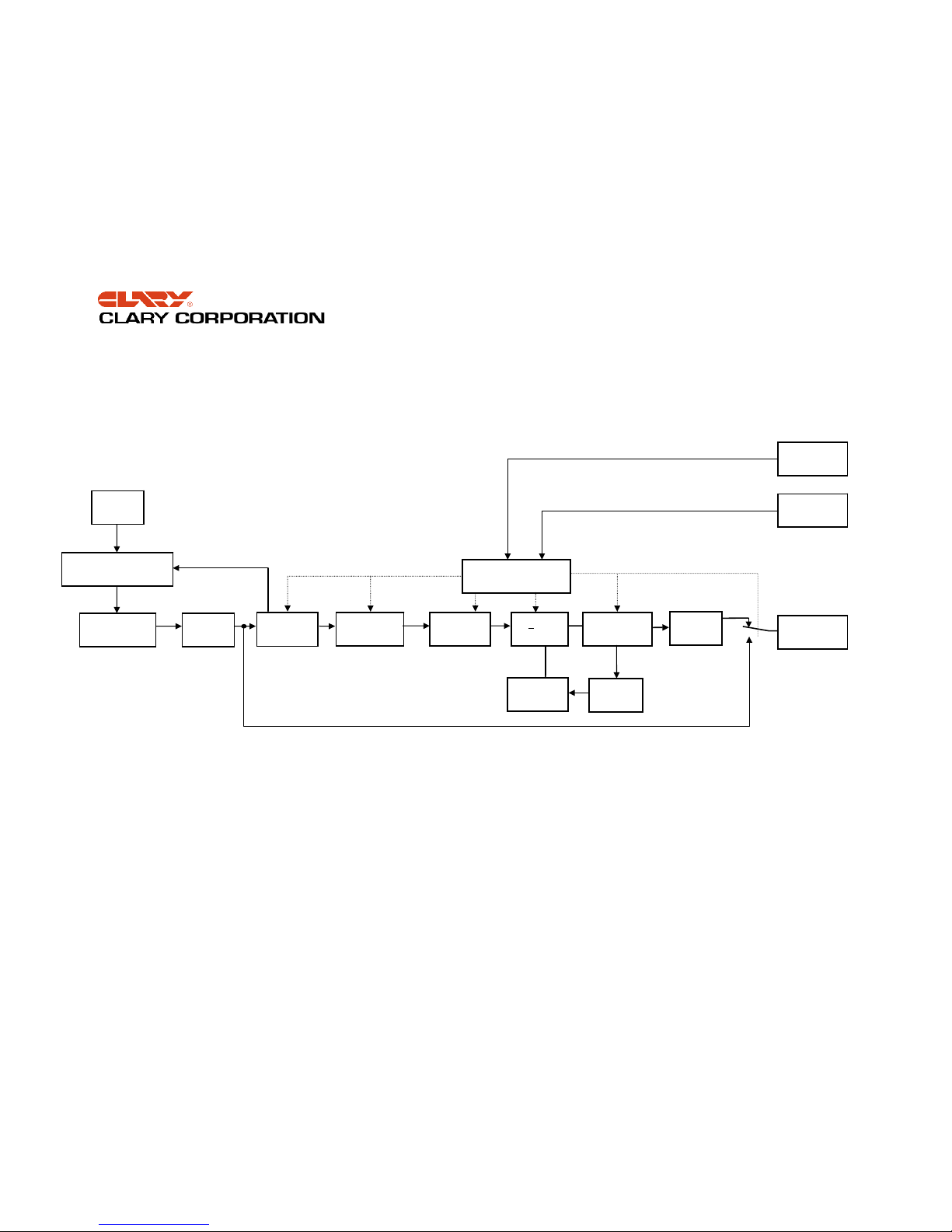
Reference the block diagram for a simplified
explanation of the system’s operation. The AC utility
source is connected to the power and microelectronics when the input switch is closed. The
input line is filtered, power factor corrected and
rectified for enhanced performance without
disturbing other equipment that may share the same
utility circuit. In SN units, an input isolation
transformer is added to accept a wide range of input
voltages for global applications. Output
transformers, SNMP adapters and many other
options are available.
The microprocessor controls an Inverter Generator
that produces a low harmonic, AC sinewave for
continuous power applications.
When the input AC utility line fails, the battery circuit
within this system takes over to ensure continuous
power. Only after properly rated power is returned,
does the microprocessor reconnect the input source
back into the system.
The microprocessor is directly tied to an external
RS232 connector port. This allows the user to
monitor and even set some of the operating
parameters. With a simple link to a personal
computer using the SNConfig software program, you
can actually view, on your monitor, the event history
of the power distribution system with the SN Series
unit as the central hub. More sophisticated users
may implement the optional SNMP package to
accomplish full Network Power Management.
Page 4
THE CONTINUOUS POWER COMPANY
FIGURE 1: SN SERIES BLOCK DIAGRAM
BYPASS LINE
EMERGENCY
CUTOFF
SWITCH
VOLTAGE
WINDOW
DETECTOR
COMMON
MODE
CHOKE
RECTIFIER
CHARGER
POWER
FACTOR
CORRECTOR
+ DC
RAILS
MICROPROCESSOR
CONTROLLER
AC
INVERTER
GENERATOR
LOAD
STANDBY
BATTERY
COMMON
MODE
CHOKE
AUTO
VOLTAGE SELECTOR
SWITCH
UTILITY
INPUT
INPUT
TRANSFORMER
DB-9
CONTACTS
DB-9
RS232

PACKAGING
our UPS has been carefully packaged to
withstand most abuse sustained during
shipment. The packing material has been
Y
specifically designed to protect this system for
normal handling, using most shipping carriers. If
there is significant damage to the carton, or if there
is any physical damage to this unit, report this to
your carrier.
These units are encapsulated in a protective wrap
that comes apart once the product is removed from
THE CONTINUOUS POWER COMPANY
the shipping carton. Save all packing material for
future use.
Take extra precaution when removing or returning it
to the box. Because this unit contains a battery, it
can be quite heavy. Never attempt to unpackage
the equipment unassisted.
The packaging also contains important information
!
on use and care as well as valuable warranty
information. Read all materials before storing this
literature with your other valuable product
documents.
Page 6
PHYSICAL DESCRIPTION
THE CONTINUOUS POWER COMPANY
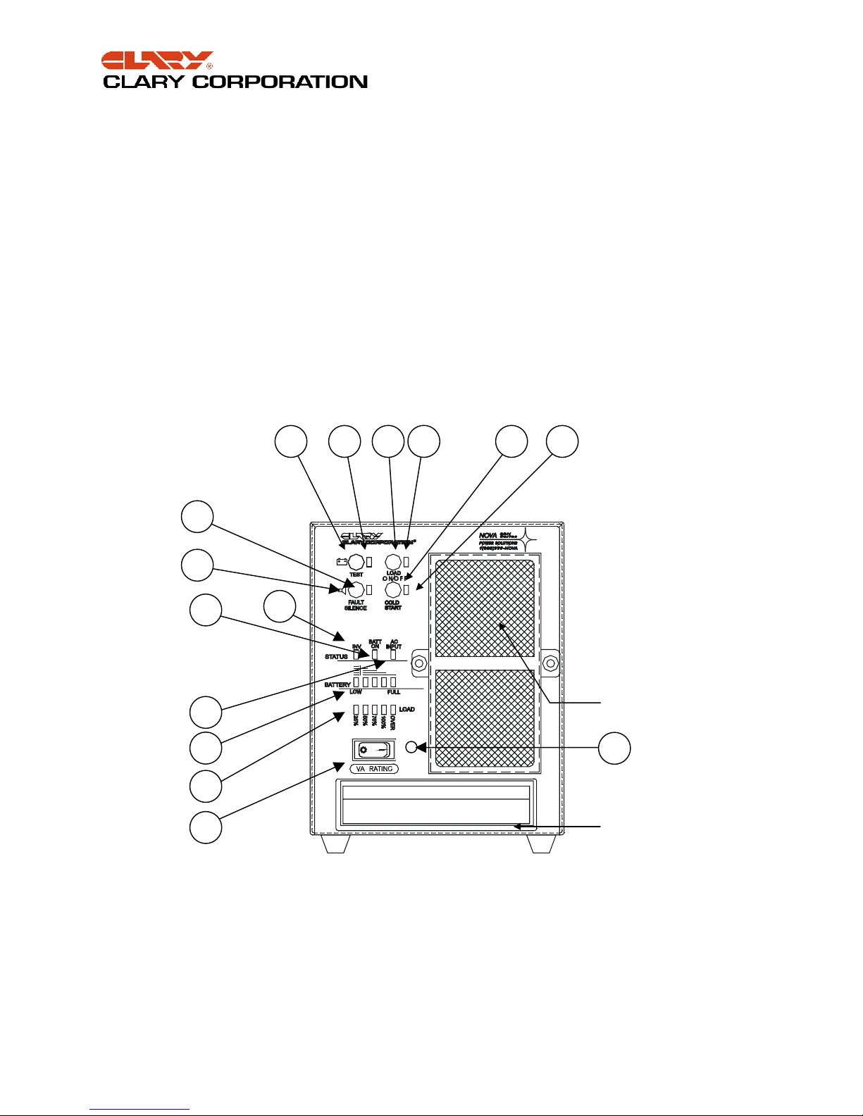
his section will point out and illustrate the
various indicators, functions and controls of
the SN Series UPS. Pictured is the front view
T
of the system, then followed by the rear view.
The important attributes of the SN Series unit are
numbered to assist you in locating them on your
machine and also to fully explain its function and
how it relates to system operation.
Numbers on the drawing will correspond to the
operating component’s name at the bottom with a
brief identification. In the next section, a complete
explanation of all numbered items will be enhanced
to ensure you have a full understanding of the
operation of this system.
8 7
13
10
9
11
Visual indicators used on the front panel are long
lasting, very efficient, light emitting diodes (LED).
When operating the push-button switches, always
hold the switch in for at least two seconds to insure
function confirmation. This feature has been
implemented into the system design to avoid
inadvertent operation of any of the user-available
functions.
The rear panel has been engineered with the user’s
multiple applications in mind. In some models, two
of the output receptacles have been rotated to allow
attachment of a plug-in transformer without hanging
over the back of the unit or interfering with another
outlet. The outputs can be switched on or off.
6
12
14
2
4
5
1
3
AIR INTAKE,
COOLING
15
LIFTING
HANDLE
FIGURE 2: FRONT VIEW, SN1000
Page 7
 Loading...