

Page 1
Owner’s
Operating
Manual
GT SERIES
CONTINUOUS POWER SYSTEM
MODELS COVERED:
GT1000
GT1250
GT1500
GT2000
CLARY CORPORATION
1960 S. Walker Avenue
Monrovia, California 91016
Telephone 626-359-4486
800-44 CLARY
Fax. 626-305-0254
World Wide Web HTTP: // WWW.CLARY.COM
E-Mail SALES @ CLARY.COM
Information contained herein is the property of Clary Corporation, is proprietary, confidential, and not to be
disclosed, disseminated or used except for the purpose provided by
CLARY CORPORATION
P/N 510-12402 REV A
Page 2

THE CONTINUOUS POWER COMPANY
TABLE OF CONTENTS
TITLE PAGE
TABLE OF CONTENTS 2
INTRODUCTION 3
TECHNICAL DESCRIPTION 4
PACKAGING 6
PHYSICAL DESCRIPTION 7
SUMMARY OF INDICATORS AND CONTROLS 11
INSTALLATION 12
OPERATION 13
SIGNALS AND INTERFACING 14
SPECIFICATIONS 15
CARE AND MAINTENANCE 17
SERVICE AND REPAIR 18
Page 3
INTRODUCTION
THE CONTINUOUS POWER COMPANY
ongratulations! You have selected the
highest quality protection for your continuous
C
power needs. This unit offers a quiet and
compact package with superior performance
you can depend on. You now own a GT Series
Continuous Power System (CPS) which is an all
Digital Technology product manufactured by Clary
Corporation, the first name in uninterruptible power
system (UPS) reliability. The GT designation
denotes a custom configuration offshoot from the
standard DT Series. This means the addition of a
step-up or step-down voltage conversion
transformer for global applications. The Continuous
Power System is the highest order in the hierarchy
of UPS products. When power problems occur,
there can be no compromising the reliability of your
power solution. The GT Series Continuous Power
System is your complete
power solution.
IMPORTANT SAFETY INSTRUCTIONS,
SAVE THESE INSTRUCTIONS
This Users Manual is provided with your new GT
Series unit. It will enhance your understanding of
the product and its functions. Read this handbook
carefully in the order it is presented prior to
operating your unit. This will save you time and
effort in your installation and application. The
illustrations will also familiarize you with this unit’s
operating modes and indications. Always operate
the unit within the guidelines and specifications
given to maximize the unit's efficiency and lifetime.
Also, your understanding of the product is essential
in providing you years of service for your continuous
power requirements.
This unit has been manufactured and tested to meet
specific safety standards. It meets UL and FCC
requirements and complies with safety performance
standards.
This symbol indicates that
dangerous voltage constituting
a risk of electrical shock is
present within the unit.
This symbol indicates that there
are important operating and
maintenance instructions in the
!
literature accompanying this
unit.
CAUTION
RISK OF ELECTRIC
SHOCK DO NOT OPEN
!
This manual contains important safety instructions that should be followed during installation and maintenance of
the UPS and batteries. Be aware of the following symbols and their meaning as they appear throughout the
manual:
This equipment generates and uses radio frequency energy and if not
installed and used properly in strict accordance with the manufacturer's
instructions, may cause interference to radio and television reception. All
units in this manual have been tested and found to comply with the limits
for a Class A computing device in accordance with the specifications in
Subpart J of Part 15 of FCC Rules, which are designed to provide
reasonable protection against such interference in a commercial
installation. However, there is no
in a particular installation. If this equipment does cause interference to
radio and television reception, which can be determined by turning the
equipment off and on, the user is encouraged to try to correct the
interference by one or more of the following measures:
guarantee that interference will not occur
If necessary, the user should consult the dealer or an experienced
radio/television technician for additional suggestions. The user may find
the following booklet prepared by the Federal Communications
Commission helpful:
"How To Identify and Resolve Radio-TV Interference Problems"
This booklet is available from the U.S. Government Printing Office,
Washington, DC 20402, Stock No. 004000003454.
Reorient the receiving antenna.
Relocate the UPS wi th respect to the receiver.
Move the UPS away from the receiver.
Plug the UPS into a different outlet so that the UPS
and receiver are on different branch circuits.
Page 3
Page 4

TECHNICAL DESCRIPTION
THE CONTINUOUS POWER COMPANY
he Digital Technology (GT) Series Continuous
Power System (CPS) is a revolutionary new
concept in total power protection and
T
management. The GT Series is a
microprocessor-based UPS that now allows the user
to set most of the control feature parameters. By
directly linking a personal computer to the GT Series
RS232 port, frequency settings and operation, alarm
signals, load switching, fan operation, etc. can all be
programmed to meet specific application
requirements.
The GT Series is a true on-line, continuous power
UPS. In the tradition of Clary products, the GT
Series generates the same high quality and proven
reliability to provide the best power protection
available for today’s critical applications.
In keeping with state-of-the-art design, the power
electronics are completely governed by an on-board
microprocessor. Given the powerful memory
capability of today’s microcontrollers, this
microprocessor has evolved the UPS into an all-inone complete power distribution and monitoring
center. Not only is your critical load insured of the
most reliable and constant power available, but the
user may now continuously track status of the
supply components that keep the entire system
operational. Production downtime can now be
virtually eliminated by knowing exactly what patterns
the supply utility power maintains and by knowing
exactly the condition and life expectancy of the
battery reserve.
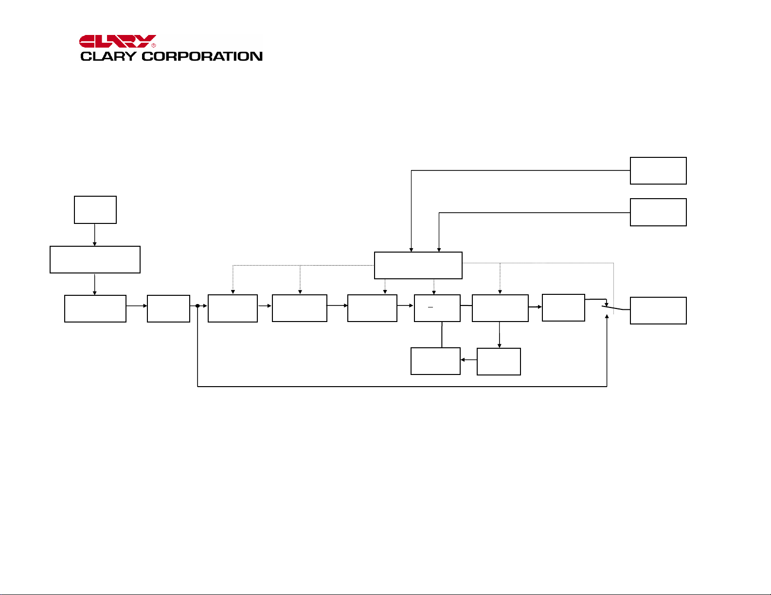
Reference the block diagram for a simplified
explanation of the system’s operation. The AC utility
source is connected to the power and microelectronics when the input switch is closed. The
input line is filtered, power factor corrected and
rectified for enhanced performance without
disturbing other equipment that may share the same
utility circuit. In GT units, a step-down, input
isolation transformer is added to accept a wide
range of input voltages for global applications.
Output transformers, SNMP adapters and many
other options are available.
The microprocessor controls an Inverter Generator
that produces a low harmonic, AC sinewave for
continuous power applications.
When the input AC utility line fails, the battery circuit
within this system takes over to ensure continuous
power. Only after properly rated power is returned,
does the microprocessor reconnect the input source
back into the system.
The microprocessor is directly tied to an external
RS232 connector port. This allows the user to
monitor and even set some of the operating
parameters. With a simple link to a personal
computer using the DT-UPS2 software program, you
can actually view, on your monitor, the event history
of the power distribution system with the GT Series
unit as the central hub. More sophisticated users
may implement the optional SNMP package to
accomplish full Network Power Management.
Page 4
Page 5
THE CONTINUOUS POWER COMPANY
UTILITY
INPUT
AUTO
VOLTAGE SELECTOR
SWITCH
INPUT
TRANSFORMER
COMMON
MODE
CHOKE
VOLTAGE
WINDOW
DETECTOR
MICROPROCESSOR
CONTROLLER
POWER
FACTOR
CORRECTOR
RECTIFIER
+ DC
RAILS
STANDBY
BATTERY
INVERTER
GENERATOR
CHARGER
BYPASS LINE
FIGURE 1: GT SERIES BLOCK DIAGRAM
AC
EMERGENCY
COMMON
MODE
CHOKE
CUTOFF
SWITCH
DB-9
CONTACTS
DB-9
RS232
LOAD
Page 6
THE CONTINUOUS POWER COMPANY
PACKAGING
our UPS has been carefully packaged to
withstand most abuse sustained during
shipment. The packing material has been
Y
specifically designed to protect this system for
normal handling, using most shipping carriers. If
there is significant damage to the carton, or if there
is any physical damage to this unit, report this to
your carrier.
These units are encapsulated in a protective wrap
that comes apart once the product is removed from
the shipping carton. Save all packing material for
future use.
Take extra precaution when removing or returning it
to the box. Because this unit contains a battery, it
can be quite heavy. Never attempt to unpackage
the equipment unassisted.
The packaging also contains important information
!
on use and care as well as valuable warranty
information. Read all materials before storing this
literature with your other valuable product
documents.
Page 6
Page 7
PHYSICAL DESCRIPTION
THE CONTINUOUS POWER COMPANY
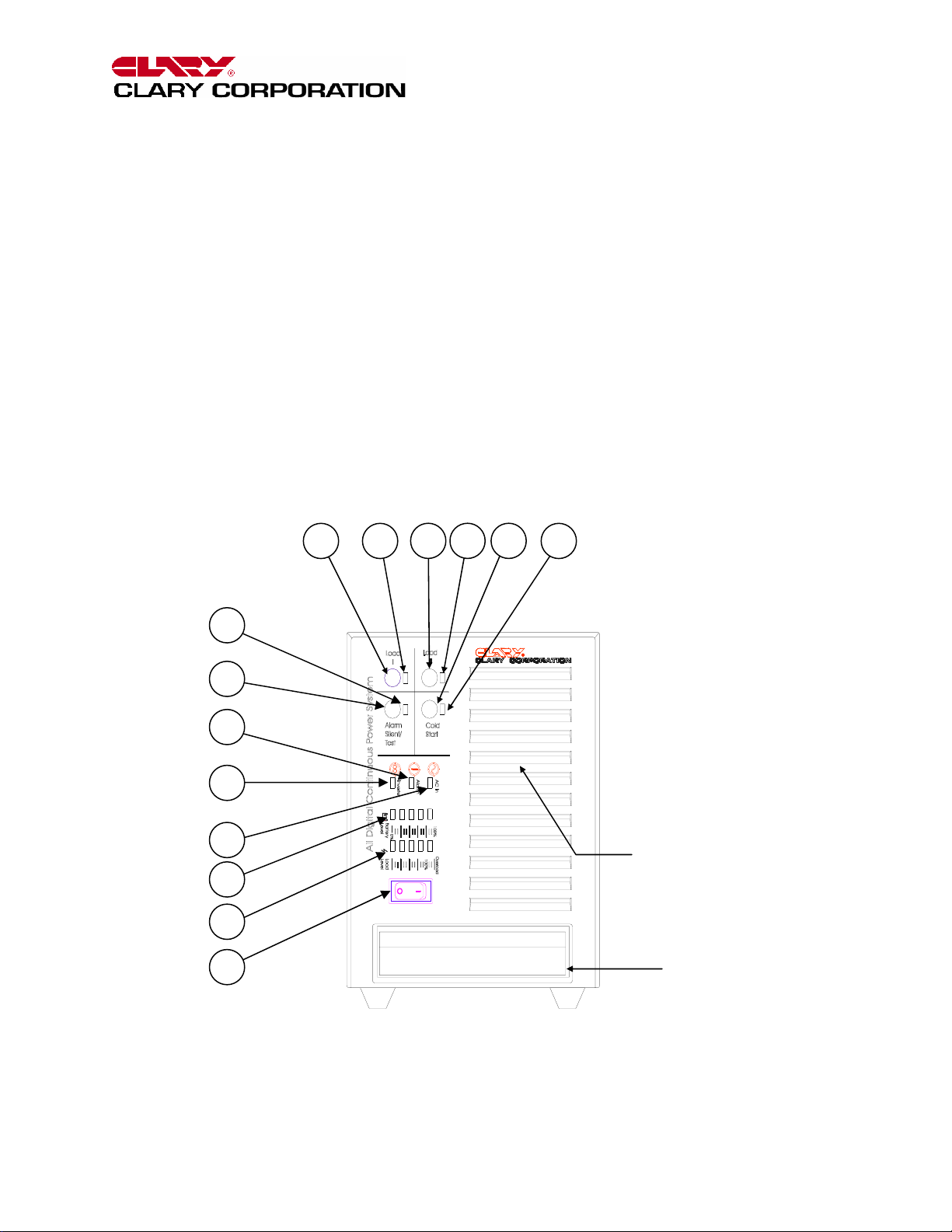
his section will point out and illustrate the
various indicators, functions and controls of
the GT Series UPS. Pictured is the front view
T
of the system, then followed by the rear view.
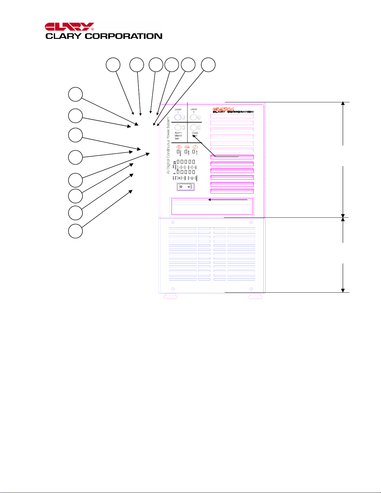
The important attributes of the GT Series unit are
numbered to assist you in locating them on your
machine and also to fully explain its function and
how it relates to system operation.
Numbers on the drawing will correspond to the
operating component’s name at the bottom with a
brief identification. In the next section, a complete
explanation of all numbered items will be enhanced
to ensure you have a full understanding of the
operation of this system.
8 7
13
9
10
11
Visual indicators used on the front panel are long
lasting, very efficient, light emitting diodes (LED).
When operating the push-button switches, always
hold the switch in for at least two seconds to insure
function confirmation. This feature has been
implemented into the system design to avoid
inadvertent operation of any of the user-available
functions.
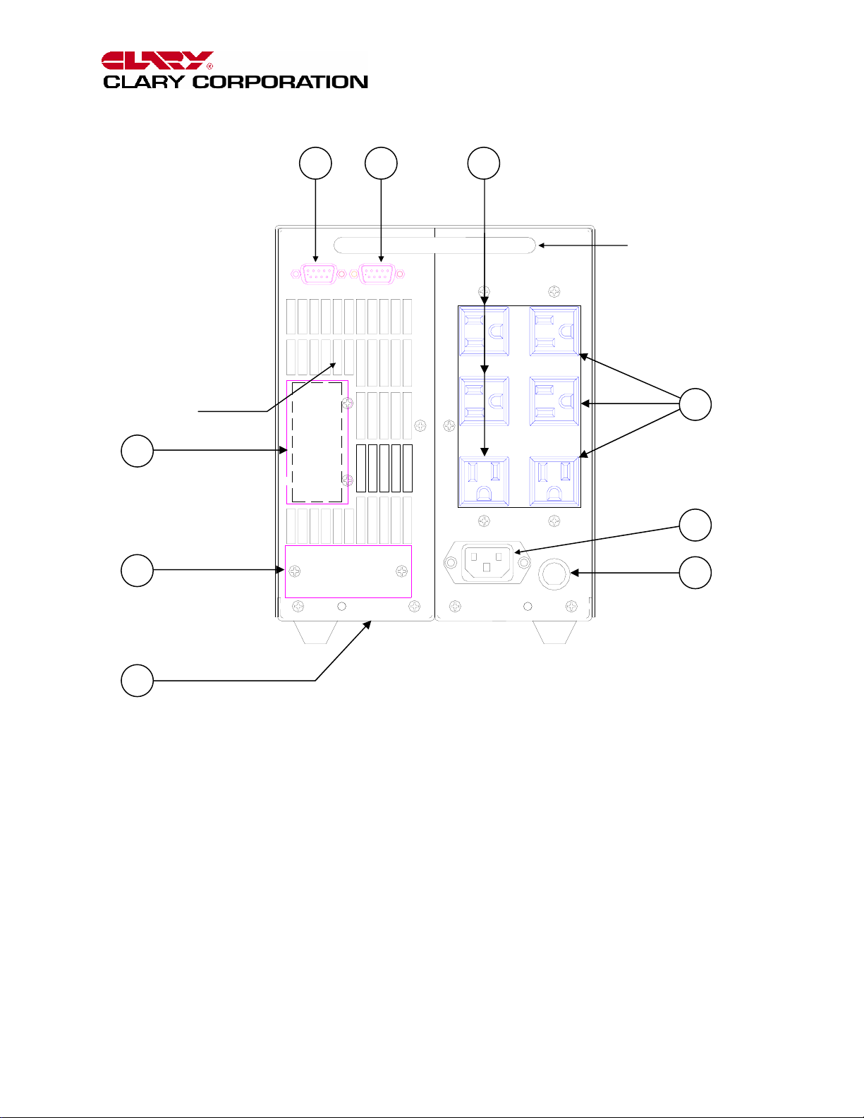
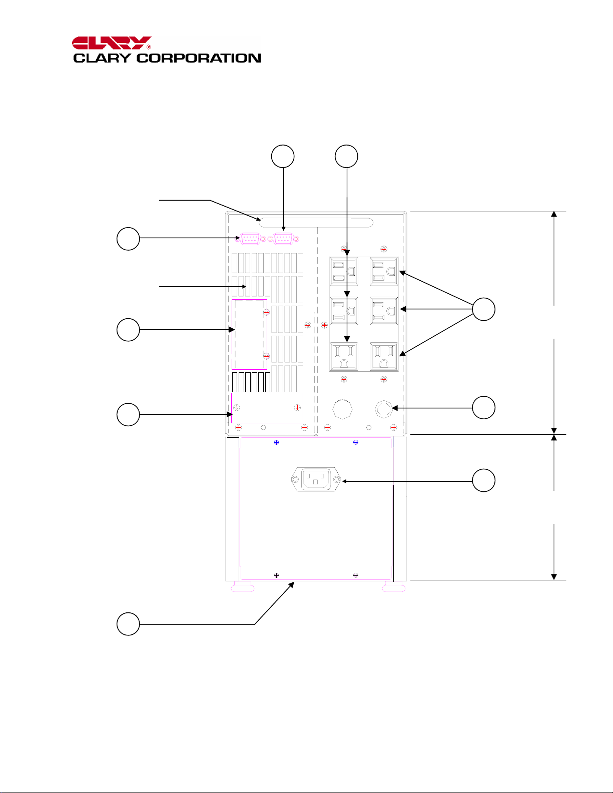
The rear panel has been engineered with the user’s
multiple applications in mind. In some models, two
of the output receptacles have been rotated to allow
attachment of a plug-in transformer without hanging
over the back of the unit or interfering with another
outlet. Two load outputs are provided with two or
three receptacles per output. The outputs can be
independently switched on or off.
6
12
14
3
2
4
5
1
AIR INTAKE,
COOLING
LIFTING
HANDLE
FIGURE 2: FRONT VIEW, GT1000
Page 7
Page 8
THE CONTINUOUS POWER COMPANY
13
12
14
3
2
4
5
1
8 7
10
9 11
6
AIR INTAKE,
COOLING
LIFTING
HANDLE
UPS
COMPARTMENT
TRANSFORMER
COMPARTMENT
FIGURE 3: FRONT VIEW, GT1250 – GT2000
GLOBAL FRONT PANEL CALLOUTS
1 SYSTEM POWER SWITCH 9 LOAD I ACKNOWLEDGE INDICATOR
2 AC In - Input line indicator 10 Load II - Enable switch for a row of output
3 Inverter - Inverter operating indicator
4 Battery Level - Charge/discharge indicators 11 LOAD II ACKNOWLEDGE INDICATOR
5 Load Level - Output capacity indicators 12 Alarm Silent/Test - Dual function switch
6 Cold Start - DC start switch 13 ALARM SILENT/TEST ACKNOWLEDGE
7 COLD START ACKNOWLEDGE INDICATOR INDICATOR
8 Load I - Enable switch for a row of output 14 Alarm - Fault indicator
receptacles
receptacles
Page 8
Page 9
THE CONTINUOUS POWER COMPANY
AIR EXHAUST,
COOLING
23
17
20 21
18
LIFTING
HANDLE
19
15
16
22
FIGURE 4: REAR VIEW, GT1000
GLOBAL REAR PANEL CALLOUTS
15 INPUT - AC Line cord inlet 19 120VAC OUTPUT (LOAD 2)- System output,
16 INPUT LINE FUSE – Input line protection
17 DC INPUT - Auxiliary battery connector 20 SIGNAL - Open-collector signal contacts
18 120VAC OUTPUT (LOAD 1)- System output, 21 RS232 - Computer communications signals
left row
22 IDENTIFICATION LABEL
23 SNMP – (Optional) Slot for network monitoring
Page 9
right row
Page 10
THE CONTINUOUS POWER COMPANY
LIFTING
HANDLE
20
AIR EXHAUST,
COOLING
23
17
21
18
19
COMPARTMENT
16
UPS
22
15
TRANSFORMER
COMPARTMENT
FIGURE 5: REAR VIEW, GT1250 – GT2000
Page 10
Page 11
THE CONTINUOUS POWER COMPANY
SUMMARY OF INDICATORS AND CONTROLS
SYSTEM POWER SWITCH - The main control
switch that engages utility power to the entire unit.
By activating this switch it initializes normal
operation.
AC In - The utility input indicator that identifies
status of the line voltage. If the line voltage is within
the specified range, it will remain lit. If the AC input
is out of range, this indicator will flash in 1 to 2
second intervals.
Inverter - This indicator identifies the status of the
regenerated, conditioned protected output power.
This indicator will stay ON as long as protected
power is available from the power inverter generator.
Battery Level - This is the battery status bar graph.
During normal operation, this bar graph will show the
charging of the battery; all indicators lit will represent
a fully charged battery. During battery operation,
this bar graph represents a discharge meter
indicating less battery time available as each light
goes OFF.
Load Level - This is the system output capacity
status bar. The number of lights on the graph
indicate an approximate percentage of system full
load. All lights being ON would indicate full load.
Cold Start - A momentary push-button switch to
activate the system in the event no utility power is
available. The system will be allowed to start up by
using power from its internal battery. Depress this
switch, the indicator above it will light, and hold it in
until the audible alarm beeps once. The system will
maintain a load depending upon the condition of the
battery.
Load I - A momentary push-button switch that
toggles the output LOAD I AC output terminals at the
rear panel. Unless the unit is powered up using the
Cold Start switch, the output load will normally be
connected to the inverter generator output. The
indicator above the switch will be ON to represent
this. Depressing the switch can disconnect the
output. While the switch is depressed, the indicator
will blink to represent transition. Once the indicator
stops blinking, the switch can be released for a
successful transition.
Load II - A momentary push-button switch that
works identical to LOAD I except it corresponds to
the LOAD II AC output terminals at the rear panel.
SNMP – (Optional) A slot available to install an
interface card to provide system network
management.
Alarm Silent/Test - A momentary push-button
switch that controls two different functions
depending on the mode of operation. In the normal
mode of operation, if this switch is depressed and
held in, the above indicator will blink. Once it stops
blinking, the unit will perform an internal 1 to 2
minute battery check. Once the test is completed, if
the battery is below standards, the system will
indicate that the battery needs replacing. The
system will not run this battery test unless the
battery is detected to be fully charged. During
battery or abnormal operation, an audible alarm will
accompany this mode. By depressing this switch,
the adjacent indicator will blink. When it stops
blinking, the alarm will be silenced. Once the fault or
reason for the alarm is corrected, this audible alarm
condition will automatically reset. The audible alarm
can be re-enabled during abnormal conditions by
pressing and holding the switch again.
NOTE - All switches must be held in for at least two
seconds to engage their function. This is to prevent
any inadvertent switch operation.
!
Alarm - This is a fault indicator that will light in the
event that the inverter generator is non-operable.
This could be due to an overtemperature situation or
an inverter malfunction.
INPUT – An IEC inlet is provided for universal input
cord connections.
FUSE – The power protection device for the input
circuitry.
DC INPUT - The auxiliary battery input connector to
add optional batteries for extended backup time.
120VAC OUTPUT (Load I & Load II) - The output
groupings that can be independently controlled by
the corresponding front panel switch. During normal
operation, inverter generator power is supplied at
these outlets. Three separate hardwire circuits have
been provided. They are individually protected by
circuit breakers.
SIGNAL - A DB-9 subminiature, female connector
that outputs the open-collector signal contacts that
generate a low state during utility interrupt, low
battery and inverter off conditions.
RS232 - A DB-9 subminiature, female connector that
outputs true RS232 computer communications
signals.
IDENTIFICATION LABEL - The model number and
!
serial number of the system is located here. This
label is located on the underside of the unit Always
refer to this information when corresponding with the
factory.
Page 11
Page 12

THE CONTINUOUS POWER COMPANY
INSTALLATION
f the unit is to be stored, it is recommended to
refresh the internal battery at least once every 90
days. To do this, plug the system in, position the
I
power On/Off switch to "ON" and allow the unit to
idle for at least 24 hours.
The GT unit is designed for installation in a
protected environment. Some important points to
consider when positioning a unit for operation:
A properly rated (preferably dedicated) outlet is
accessible for the six-foot power cord, supplied
with the unit. It is not recommended to modify the
supplied cord in any way nor should an extension
cord of any kind be used.
The cord paths in the system installation should
remain clear of foot traffic or anything else that
may disturb permanent connection.
The installation site should maintain an ambient air
temperature of less than 104
o
F (40oC). When the
environment for the system remains cooler during
operation, there is less stress on the batteries and
the internal electronics.
The air inlets, vents and fan should not be
obstructed or blocked in any way. The more
breathing space the system has, the cooler it
operates.
The air should remain free from excessive dust
and chemical fumes.
Once a location has been selected and the unit is
installed, it is ready for operation.
Allow at least 8 hours, after the system is first
installed, to fully charge the internal battery to a
maximum state.
Page 12
Page 13

OPERATION
THE CONTINUOUS POWER COMPANY
nce the system has been properly installed,
it is ready to operate. The following
O
power and also how to start-up with no AC power
available.
Normal Operation on AC Start-Up:
• Verify that the unit is plugged into properly rated
• Position the System Power Switch to the ON
The system will proceed through about a threesecond diagnostic where all the lights will sequence
ON then OFF. The AC IN light will flash several times
and the audible alarm will give a short burst. The
AC IN light will then stay ON and the battery level
meter will light to at least an 80% level. The
INVERTER light will come ON. and power will be
available at all the output receptacles. The LOAD I
and LOAD II will come ON.
Actual load may be connected at any time during
this procedure, however, power is only available
when the light above either of the LOAD switches is
ON continuously.
Battery Operation after AC Start-Up:
• Unplug the unit from the standard wall outlet.
The AC ON light will flash at two to three second
intervals. Within 5 seconds, the audible alarm will
sound at half-second intervals.
• Push and hold in the ALARM SILENT/TEST
If operation were to continue in this mode, the
BATTERY LEVEL meter would start to turn OFF, one
light at a time starting from the top. Once the last
light is left and the preprogrammed battery
availability time (usually about 2 minutes) is
reached, the alarm will sound in a constant tone.
Had the alarm been previously silenced, it would still
re-enable to alert the user of limited operation. This
alarm can also be silenced as before. If the unit is
allowed to operate further, it will time out and shut
off completely. If power were to return, the unit will
automatically restart and return to the condition it
was in at the moment it went into Battery Mode.
DC Start Operation (Cold Start)
If no utility power is available at the time backup
power is required; the unit may be started to
accomplish abbreviated tasks. The limitations of the
battery prevent extended operations at full load.
• Position the System Power Switch to the ON
procedures will explain how to start-up the
system while plugged into rated electrical
electrical power.
position.
switch until the audible alarm is inhibited.
position.
• Push and hold in the COLD START switch until
the audible alarm beeps.
The unit will start up similarly to normal AC start-up
except the AC IN LED will continue to flash. The
LOAD outputs will come up in the OFF mode when
using the COLD START feature.
Loading the System
The system can be loaded up to full rated load. As
load is applied, the LOAD METER will start to turn
ON. Once full load is achieved, the full LOAD
METER should be lit. As additional load is applied,
the top red OVERLOAD LED will come ON. If too
much overload is applied, the audible alarm will
sound. If this increased load is not removed within
five seconds, the unit will discontinue output
operation and latch into an alarm condition. The
audible alarm will continue to sound and the ALARM
LED will light. Reducing the load and cycling the
System Power Switch OFF then ON can reset the
system.
Programming the Outputs:
The outputs on startup can be programmed ON or
OFF. The default mode is programmed to turn both
load circuits ON whenever you power up the UPS on
AC startup. They will stay energized until you turn
OFF the UPS, the batteries run down during a power
outage or if the appropriate load button is pressed.
To program both loads to be OFF when the UPS is
turned ON:
• Turn the UPS OFF
• Turn the UPS ON while pressing and holding the
ALARM SILENT/TEST switch.
• The UPS will come ON with both loads OFF and
will remember this setting each time the unit is
turned ON.
To program both loads to come ON:
• Turn the UPS OFF.
• Turn the UPS ON while pressing and holding
both LOAD I and LOAD II switches (this
definitely requires both hands). The UPS will
remember this combination the next time it is
powered ON.
To program LOAD I or LOAD II to come ON
individually at startup:
• Turn the UPS OFF.
• Turn the UPS ON while pressing and holding
either LOAD I or LOAD II switches.
The UPS will remember this combination the next
time it is powered ON.
.
Page 13
Page 14
THE CONTINUOUS POWER COMPANY
A
SIGNALS AND INTERFACING
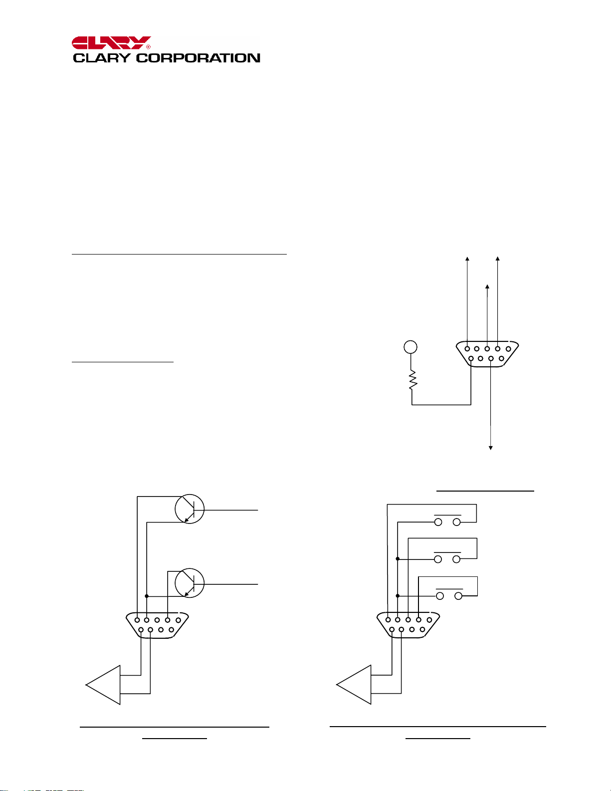
t the rear of the unit are two DB-9
subminiature, female connectors. These are
provided for communications links to a
computer or sophisticated monitoring device.
SIGNAL provides open-collector outputs that
typically signal Utility Interrupt and Low Battery
conditions. A system shutdown feature is also
available on this port. Applying a short between Pin
6 and Pin 7 will cause the system to shutdown in
battery mode. This conserves the battery life once
an orderly shutdown has been accomplished. The
system may be configured to shutdown by applying
a +5 to +12V signal across the appropriate pins.
Contact the factory for configuration details.
RS232 is a true computer communications signal
port.
The open-collector signal outputs can be converted
to dry contact closures, as an option. Below is the
pin out of the two connectors with their default
assignments:
OPEN-COLLECTOR CONNECTOR (SIGNAL)
2- UTILITY INTERRUPTED SIGNAL
4- COMMON SIGNAL RETURN
5- LOW BATTERY SIGNAL
6- + UPS SHUTDOWN
7- - UPS SHUTDOWN
RS232 CONNECTOR
2- TRANSMITTING DATA (TX)
3- RECEIVING DATA (RX)
6 & 8- DATA SET READY
5- SIGNAL GROUND
LOW BATTERY
5
TX
6
DSR
RX
3
8
2
+5V
1KΩ
GND
DB-9F
RS232 CONNECTOR
LOW BATTERY
DB-9F
SYSTEM
SHUTDOWN
SIGNAL: OPEN-COLLECTOR CONTACT
5
6
+
-
CONNECTOR
UTILITY INTERRUPTED
1
9
SYSTEM
SHUTDOWN
SIGNAL: DRY CONTACT CLOSURE (OPTION)
Page 14
INVERTER ACTIVE
1
5
6
+
UTILITY INTERRUPTED
DB-9F
9
-
CONNECTOR
Page 15
THE CONTINUOUS POWER COMPANY
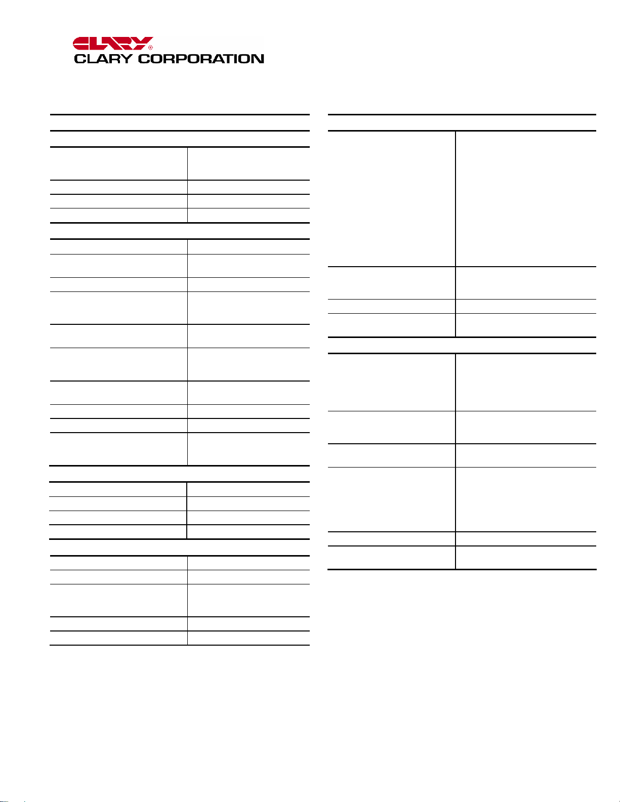
SPECIFICATIONS
ELECTRICAL
Input
Voltage (Auto-selectable) 120VAC or 220VAC or
Power Factor Corrected IAW MIL STD. 1399 Sec. 300
Frequency 45 to 65Hz
Current See Model Selection Guide
Output
Voltage
Frequency 50Hz / 60Hz (software select)
Current See Model Selection Guide
Crest Factor Ratio
(Non-linear load and
less than 5% THD) Typical
Total Harmonic Distortion (THD) 3% Typ; 5% Max.
Dynamic Response
Overload 110% for 10 Minutes;
Efficiency (UPS) 88% Typ.
Battery Back-up See Model Selection Guide
UPS Protection Input and Output Short Circuit;
ENVIRONMENTAL
Operating Temperature 32oF to 104oF (0oC to 40oC)
Humidity 0% to 95% Non-condensing
Altitude Sea Level to 10,000 Feet
Audible Noise 39-42 dBA at Five Feet
MECHANICAL
Input Inlet (6’ Line Cord Provided) IEC 320
Output (Qty.) (6) NEMA Type 5-15R
Cooling Low Velocity, Temperature
Dimensions See Model Selection Guide
Weight See Model Selection Guide
240VAC +10%, -20%
(without Battery discharge)
120VAC ± 3%
Line Sync (software select)
@50% Load Up to 4.8:1
@75% Load Up to 3.2:1
@100% Load Up to 2.4:1
(@100% Non-linear load)
±4% for 100% Step Load
Change,
0.5 Millisecond Recovery Time
200% for 0.5 Seconds
Input and Output Overload;
Excessive Battery Discharge
Controlled Reversible Forced
Air
DESIGN
Standard Features Power Factor Corrected, Digital
Specifications UL Design
MTBF In Excess of 100,000 Hours
Typical Recharge Time to
85% Capacity at 100% Load
CONTROLS AND INDICATORS
Visual Indicators
Sequenced LEDs
Single LED
Front Panel Controls Power On, Cold Start
Audible Alarms Utility Interrupt, Inverter Failure
RS232 Data Interface (DB-9F) Full Interactive, Remote Computer
Open-Collector (DB-9F) Allows Alarm Function Monitoring
Optional SNMP Interface
(RJ45)
Specifications subject to change without notice. 7/99
Regenerative™ On-Line, Sinewave
Inverter Powers Load Continuously
Extended Brownout Protection
Designed for Non-linear Loads
Continuous Operation on
-20%,+12% Line
Automatic Bypass
RS232 Data Interface
Software Selectable Output
Frequency
AC Output Switch
Auxiliary Battery Connector
Optional SNMP Interface
FCC Class A
IEEE 587/ANSI C62.41
8 Hours
Battery Level, Load Level
AC Input, Inverter On, Fault
Fault Silent, AC Output,
Cold Start, Replace Battery
Fault Silence, Battery Test
AC Output On/Off
Overload, Low Battery
Monitoring and Control of UPS
Functions.
Compatible with Systems
Enhancement UPS Monitor &
Control Software
Allows Full Control and Monitoring
Over Network Connection.
Page 15
Page 16
DESCRIPTION
Nominal VA
(Max Watts)
Input Current
Amps (@120VAC)
Output Current
Amps
Input Plug (Standard)
NEMA Type
Battery Backup Time
Minutes
@100%/@50%
Load
Weight lbs(kg)
Dimensions HxWxD
in(cm)
THE CONTINUOUS POWER COMPANY
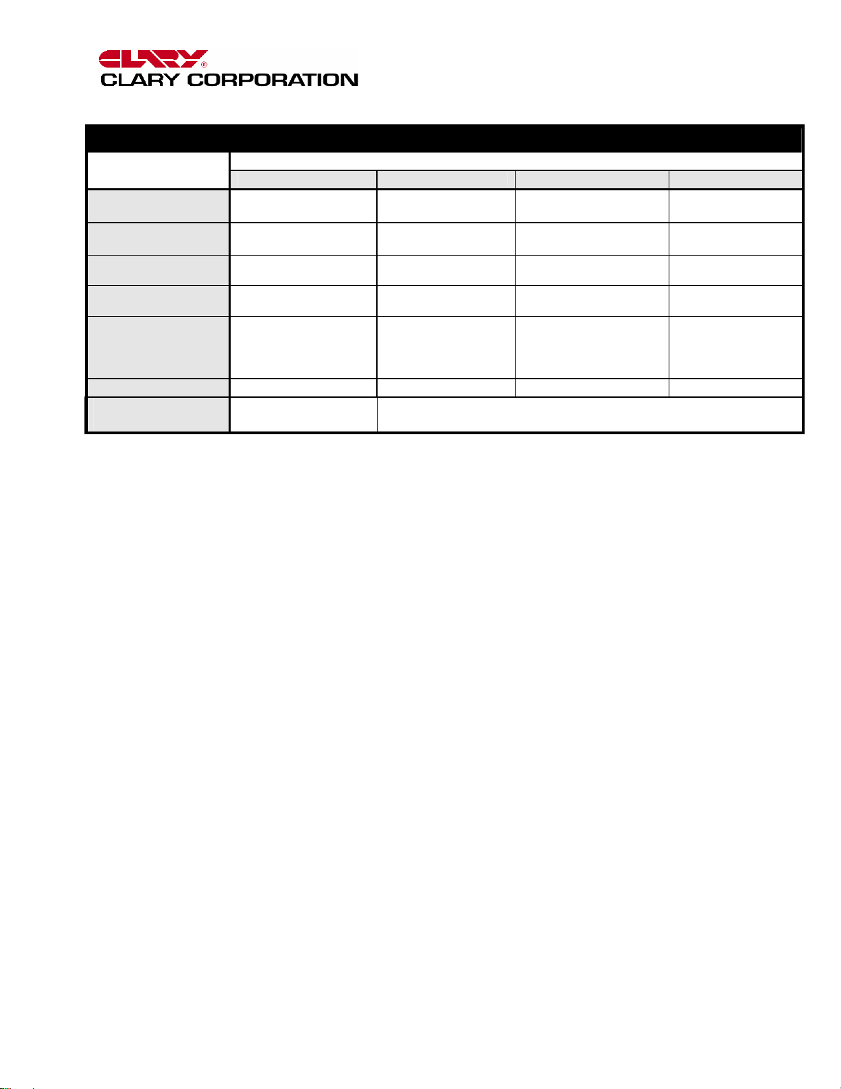
MODEL SELECTION GUIDE
MODEL NUMBER
GT1000 GT1250 GT1500 GT2000
1000
(700)
7.2 8.8 10.7 14.3
8.3 10.4 12.5 16.7
5-15P 5-15P 5-15P 5-20P
5/17 7/21 5/17 5/18
55 (25) 80 (36) 80 (36) 100 (45)
9.1(23) x 6.9(17.5) x
21(53)
1250
(875)
1500
(1050)
14.1(36) x 6.9(17.5) x 21(53)
2000
(1400)
Page 16
Page 17
THE CONTINUOUS POWER COMPANY
CARE AND MAINTENANCE
his device is designed to be maintenance-free.
It can be cleaned with a damp cloth or
nonabrasive cleanser.
T
WARNING
cleaning solutions. Keep cleaning solutions out of
the electrical receptacles on this device.
Be sure filters, vents and fans are kept free from
accumulation of dust, dirt or lint. Below is a simple
maintenance schedule that will assist you in keeping
the system at its peak level of performance and also
minimizing potential premature failures.
Your system contains sealed maintenance-free
batteries. When situated in the proper environment,
with the proper charging and limited cycling, these
batteries can last many years.
WARNING
High voltage exists within the unit which could cause
electrical shock. Servicing of batteries should be
performed or supervised by personnel
knowledgeable of batteries and the required
precautions. Keep unauthorized personnel away
from batteries. When replacing batteries, use the
same number and type batteries.
CAUTION
in a fire. The battery may explode.
SHOCK DO NOT OPEN
: Do not use ACETONE-BASE
: Never attempt to service batteries.
- Do not dispose of battery or batteries
CAUTION
RISK OF ELECTRIC
!
CAUTION
batteries. Released electrolyte is harmful to the skin
and eyes. It may be toxic.
CAUTION
shock and high short circuit current. The following
precautions should be observed when working on
batteries.
1. Remove watches, rings, or other metal objects.
2. Use tools with insulated handles.
3. Wear rubber gloves and boots.
4. Do not lay tools or metal parts on top of
5. Disconnect the charging source prior to
6. Determine if the battery is inadvertently
The internal rechargeable battery is recyclable. At
the end of its useful life, under various state and
local laws, it may be illegal to dispose of this battery
into the municipal waste stream. Check with the
factory for details in your area for recycling options
or proper disposal.
- Do not open or mutilate the battery or
- A battery can present a risk of electrical
batteries.
connecting or disconnecting battery terminals.
grounded. If inadvertently grounded, remove
source of ground. Contact with any part of a
grounded battery can result in electrical shock.
The likelihood of such shock will be reduced if
such grounds are removed during installation
and maintenance.
RECOMMENDED PREVENTATIVE MAINTENANCE SCHEDULE
TIME TASK TOOLS REQ’D INITIAL;
Every 6 mo. Test battery operation, check back-up time None
Every 12 mo. Thoroughly clean unit Vacuum, brush
Every 42 mo. Replace battery 3/8 Hex Nut Driver
Every 72 mo. Replace cooling fan Screwdriver
Page 17
Page 18

THE CONTINUOUS POWER COMPANY
SERVICE AND REP AIR
our GT Series UPS is backed by one of the
finest customer service teams available.
Write or call them at any time to obtain more
Y
information about your unit.
Clary Corporation
1960 S. Walker Avenue
Monrovia, CA 91016
1-800-551-6111
If a problem should occur, it is important that you
obtain a Return Material Authorization (RMA)
number from the Service Department to process any
unit returned to the factory. In consulting the factory,
always have the unit model number and serial
number at hand. This information is located on the
identification label and is essential in retrieving your
unit’s performance and history record.
The RMA number issued to you should appear on
the outside of the carton, if the unit is returned, or on
any correspondence regarding your unit. When
shipping a unit back to the factory, try to use the
original packing container and shipping materials.
The Service Department cannot take responsibility
for any unit damaged in return shipment. All units
must be returned prepaid to:
Clary Corporation
GT Service Center
1960 S. Walker Avenue
Monrovia, CA 91016
Page 18
Page 19

THE CONTINUOUS POWER COMPANY
NOT USED
Page 19
 Loading...