


®
®
3649 Cane Run Road . Louisville, KY 40211-1961
877-244-9340 . Fax: 877-414-4316
www.clarusenvironmental.com
SECTION: C1.20.130
CL0020
0911
Supersedes
New
Turbine STEP Systems
OWNER'S MANUAL
Congratulations on the purchase of the Clarus Environmental Turbine
STEP System. This system will provide years of trouble-free service
when installed according to the manufacturer recommendations.
This manual incorporates the installation, operation, maintenance,
and service instructions into one document to aid in the ownership
of a Clarus Environmental onsite wastewater product. Please read
and review this manual before installing the product. Many items
contained within, when followed correctly, will not only ensure a long
and problem-free life for the system, but also save time and money
during installation. Should further assistance be necessary please call
Clarus Environmental at 1-877-244-9340.
Table of Contents
Safety Instructions ............................................................................ 1
Limited Warranty...............................................................................2
General Instructions ......................................................................... 2
Typical Filtered STEP System ..........................................................3
Discharge Pipe & Pump Installation ................................................. 4
Floats and Float Tree Installation ..................................................4-6
Final Assembly ................................................................................. 7
System Wiring Instructions ............................................................... 7
Junction Box Wiring .......................................................................... 8
Startup .............................................................................................. 8
Operation ......................................................................................... 9
Maintenance ..................................................................................... 9
Replacement Parts ......................................................................... 10
Engineered Systems ...................................................................... 11
Owner’s Information
GENERAL
The Turbine STEP System is designed to be an easily installed dropin pump vault that does not require an additional pump chamber.
However, it can be installed in a secondary pumping chamber. By
utilizing a turbine efuent pump, high head pressures are achieved.
Designed for convenience, the lters, as well as the oat tree, are
easily removed for servicing. The lter has 924 linear feet of 1/16"
ltration. This large surface area ensures adequate ltering and a
longer interval between servicing.
Safety Instructions
TO AVOID SERIOUS OR FATAL PERSONAL INJURY OR MAJOR
PROPERTY DAMAGE, READ AND FOLLOW ALL SAFETY INSTRUCTIONS IN MANUAL AND ON PUMP.
THIS MANUAL IS INTENDED TO ASSIST IN THE INSTALLATION
AND OPERATION OF THIS UNIT AND MUST BE KEPT WITH
THE PUMP.
This is a SAFETY ALERT SYMBOL.
When you see this symbol on the pump or in the
manual, look for one of the following signal words
and be alert to the potential for personal injury or
property damage.
Warns of hazards that WILL cause serious personal
injury, death or major property damage.
Warns of hazards that CAN cause serious personal
injury, death or major property damage.
Warns of hazards that CAN cause personal injury
or property damage.
Indicates special instructions which are very
important and must be followed.
Model Number: ______________________ Date Code: _________________
Job Name: ______________________________________________________
Dealer: _________________________________________________________
Date of Purchase: _______________________________________________
Contractor: _____________________________________________________
Date of Installation: _______________________________________________
System Readings During Operation: Voltage __________ Amps _________
© Copyright 2011. All rights reserved.
THOROUGHLY REVIEW ALL INSTRUCTIONS AND WARNINGS
PRIOR TO PERFORMING ANY WORK ON THIS SYSTEM.
MAINTAIN ALL SAFETY DECALS.
According to the state of California (Prop 65), this product contains chemicals known to
the state of California to cause cancer and birth defects or other reproductive harm.
REFER TO WARRANTY ON PAGE 2.

Limited Warranty
Manufacturer warrants, to the purchaser and subsequent owner during
the warranty period, every new product to be free from defects in material and workmanship under normal use and service, when properly
used and maintained, for a period of one year from date of purchase
by the end user, or 18 months from date of original manufacture of the
product, whichever comes rst. Parts that fail within the warranty period,
one year from date of purchase by the end user, or 18 months from
the date of original manufacture of the product, whichever comes rst,
that inspections determine to be defective in material or workmanship,
will be repaired, replaced or remanufactured at manufacturer's option,
provided however, that by so doing we will not be obligated to replace
an entire assembly, the entire mechanism or the complete unit. No
allowance will be made for shipping charges, damages, labor or other
charges that may occur due to product failure, repair or replacement.
This warranty does not apply to and there shall be no warranty for
any material or product that has been disassembled without prior approval of manufacturer, subjected to misuse, misapplication, neglect,
alteration, accident or act of God; that has not been installed, operated
or maintained in accordance with manufacturer's installation instructions; that has been exposed to outside substances including but not
limited to the following: sand, gravel, cement, mud, tar, hydrocarbons,
hydrocarbon derivatives (oil, gasoline, solvents, etc.), or other abrasive
or corrosive substances, wash towels or feminine sanitary products,
etc. in all pumping applications. The warranty set out in the paragraph
above is in lieu of all other warranties expressed or implied; and we do
not authorize any representative or other person to assume for us any
other liability in connection with our products.
Contact manufacturer at, 3649 Cane Run Road, Louisville, Kentucky
40211, Attention: Customer Service Department to obtain any needed
repair or replacement of part(s) or additional information pertaining to
our warranty.
MANUFACTURER EXPRESSLY DISCLAIMS LIABILITY FOR SPECIAL, CONSEQUENTIAL OR INCIDENTAL DAMAGES OR BREACH
OF EXPRESSED OR IMPLIED WARRANTY; AND ANY IMPLIED
WARRANTY OF FITNESS FOR A PARTICULAR PURPOSE AND
OF MERCHANTABILITY SHALL BE LIMITED TO THE DURATION
OF THE EXPRESSED WARRANTY.
Some states do not allow limitations on the duration of an implied warranty, so the above limitation may not apply to you. Some states do not
allow the exclusion or limitation of incidental or consequential damages,
so the above limitation or exclusion may not apply to you.
This warranty gives you specic legal rights and you may also have
other rights which vary from state to state.
General Instructions
1. Installation must comply with all applicable electric codes, plumbing
codes and health department regulations, including, but not limited
to, the National Electrical Code, local, regional and/or state plumbing
codes, etc.
2. If the Clarus Environmental Turbine STEP System is being retrotted
into an existing septic system, it will be necessary to pump and clean
out the septic tank prior to installing. Before pumping, measure down
from the top of the septic tank to the liquid level (not the scum layer)
and record in the chart (see page 4). The top of the septic tank will
become the reference plane for measuring to correctly install your
system.
3. The inlet pipe is typically 3" above the outlet pipe. On a conventional
gravity system, once the system is pumped and cleaned, check the
dimensions from the top of the septic tank to the bottom of the inlet
and outlet pipes. Record in the chart (see page 4). Each system
varies! Therefore, don't assume a 3" difference between the inlet
and outlet.
4. An 18" hole is required in the top of the septic tank to install the STEP
system. If the hole in your septic tank is less than 18", provision must
be made to enlarge the hole to 18" (you may have to change the lid
of the septic tank).
5. If your system is not equipped with a riser, install a new Clarus
Environmental 24" or 30" diameter riser on the outlet end of the
septic tank. Follow the installation instructions provided with the
riser.
6. Unpack the STEP system from the carton. Remove everything
from the pump vault: lter pack, oat tree, discharge assembly and
instructions/hardware pack.
7. If necessary, cut a single inlet hole in the tank inlet tube (see page
11).
8. Install the two 16" long 1" schedule 80 PVC hanger pipes through
the rim holes in the pump vault and lower the pump system through
the riser and into the septic tank opening (see Fig. 1). In most cases,
the pump vault will be suspended in the septic tank by the pipe
hangers. If the septic tank is shallow, the pump vault may rest on
the tank oor. The system is designed to operate properly in either
case.
9. Install the piping from the lateral eld to the outside of the riser on
the septic tank.
© Copyright 2011. All rights reserved.
2

Typical Clarus Environmental Turbine STEP System
Clarus Environmental Turbine STEP Systems are designed for installation in septic tanks. The system should be installed through the riser
on the discharge end of the septic tank. A complete system should include: 1) Filter and pump vault, 2) Filter cartridges, 3) Float tree/ switch
assembly, 4) Efuent rated turbine pump, 5) Discharge pipe assembly, 6) Control/alarm system, 7) Junction box, 8) Prewired conduit, 9) Riser
and lid.
* * * * * * *
STATE OR LOCAL CODES
WITH NEC AND ANY OTHER
ALL WORK IN ACCORDANCE
* * * * * * *
* * * * * * * * * * * * * * * * * * * * * * * *
* * * * * * * * * * * * * * * * * * * * * * * *
55 1/2"
NOTE: BLANK TANKS ARE ALSO
INSTALLED INLET HOLE.
AVAILABLE FOR FIELD
SK2418
K
JGFEDC
H
BFLOAT CONFIGURATION
A
29"
------
---
30.5"
2.5"
---
PUMP ON PUMP OFF
---
31.5"
31.5"
---
---
---
---
---
---
30.5"
30.5"
2.5"
2.5"
2.5"
2.5"
PUMP OFF
PUMP OFF
PUMP ON
PUMP ON
ALARM
ALARM
40"
41"
---
30.5"
---
CLARUS 24 OR 30 INCH ACCESS RISER & LID
---
REDUNDANT OFF
26.5"
25.5"
8"
8"
5"
5" 5"
LOW LEVEL CUTOUT
LOW LEVEL CUTOUT
TIMER OVERRIDE
TIMER OVERRIDE
ALARM
ALARM
CLARUS 12" RISER AND LID
FROM PUMP TO SNUB OUTSIDE RISER
CLARUS DISCHARGE PIPE ASSEMBLY
SECURE EXCESS CORDAGE
(FOR FILTER REMOVAL)
CLARUS J-BOX
18" MIN. OR
(INCLUDES FLEXIBLE PVC PIPE, UNION, BALL VALVE,
AND PIPE SEAL)
4 1/2"
LOCAL CODES
PER STATE AND
FILTERED EFFLUENT
HANGER PIPES
8 1/8"
TOP OF FILTER TANK
TOP OF FLOAT TREE
"D" MIN.
33"
"F" MAX.
ALARM "A"
(BELOW, OR EVEN WITH, THE INLET HEIGHT)
"B"
SCUM LAYER
"C"
"E" MIN.
"J" MAX.
CLEAR EFFLUENT
STANDARD 4" INLET
TYPICAL
INLET LEVEL
"G"
"H" MIN.
TEE OR BAFFLE
CLARUS PUMP VAULT
TURBINE PUMP
CLARUS EFFLUENT
3 1/2" OF TETHER
LENGTH FROM CLAMP
CLARUS FILTER ASSEMBLY
17 1/8
8' 0" MIN.
FLOAT SWITCH DETAIL
SLUDGE LAYER
Fig. 1
4 FLOAT TIMED DOSING PANEL
3 FLOAT SIMPLEX CONTROL PANEL
2 FLOAT SWITCH CONTROL W/ALARM
2 FLOAT SWITCH CONTROL
3 FLOAT TIMED DOSING PANEL
OR ALARM SYSTEM
(MOUNTED ON HOUSE)
CLARUS CONTROL PANEL
RISERS FOR DRAINAGE
SLOPE GROUND AWAY FROM
4" MIN.
INLET
SIMPLEX PUMP
APPLICATION
CONDUIT
CLARUS PREWIRED
© Copyright 2011. All rights reserved.
3
"K" MIN.
1" x 16" SCH80
HANGER PIPES
3" MIN.
DUPLEX PUMP
APPLICATION

Discharge Pipe and Pump Installation
Do not lower the pump by the power cord.
10. If supplied or required, attach the check valve to the pump outlet.
Disconnect the Clarus Environmental exible pipe discharge assembly at the union on the ball valve. Connect the long part of the
discharge assembly to the pump outlet or check valve with the pump
set up outside the pump vault. If check valve is used, weephole
should be below check valve.
11. Tie off the power cord by strapping it to the upper end of the discharge
pipe. Make certain the cord cannot become entangled or obstruct
the movement of the oats. Lower the pump by the discharge pipe
into the right or left pump well of the pump vault (see Fig. 1).
Fig. 2
DISCHARGE PIPE
ASSEMBLY
1" 1¾"
1¼" 2"
2" 3"
HOLE SAW
REQUIRED
12. Reconnect the union loosely to see approximately where to install the
pipe seal through the riser wall. Remove the pump by the discharge
assembly. Drill the appropriate hole through the riser wall (see Fig.
2). Install the pipe seal through the riser wall to prevent ground
water intrusion. Disconnect the union on the discharge assembly
and install the exible pipe through the pipe seal with the union
ball valve on the inside of the riser (see Fig. 3). Solvent weld the
exible pipe to the lateral eld piping using PVC pipe cement.
13. Lower the pump by the discharge assembly back into the appropriate
pump well in the pump vault. Adjust the piping using the threaded
elbows and exible piping of the discharge assembly to achieve
proper t. Securely connect the union on the ball valve. Repeat
steps 9-12 for a second pump in a dual pump system.
Fig. 3
LID
CLARUS ACCESS RISER (24" SHOWN)
SINGLE UNION BALL VALVE
PIPE SEAL
FILTERED EFFLUENT
HANGER PIPE
Float Tree Assembly
Top of septic tank to liquid level (bottom of outlet).
Top of septic tank to bottom of inlet.
Top of septic tank to inside oor
STEP system pump vault inlet height (to the center of the inlet).
The alarm must be activated at or before the point when the efuent level reaches the bottom of the inlet pipe. If the STEP
system is being installed in an existing septic tank, the outlet pipe must be plugged.
Fig. 4
14"
TOP OF THE FLOAT TREE
10 1/2"
EXAMPLE:
14 - 3 1/2 = 10 1/2
(SO THE ALARM FLOAT SHOULD
BE SET LOWER THAN 10 1/2"
FROM THE TOP OF THE FLOAT
ROD)
3 1/2"
Fig. 5
1 2
3
4
5
6
7
8 9 10
11
12
1
13
14
16 15
17
18
20 19
22 21
DISCHARGE
FROM PUMP
13"
TOP OF THE FLOAT TREE
51"
EXAMPLE:
51 - 13 = 38
52 1/2 - 38 = 14 1/2
(SO THE ALARM FLOAT SHOULD
BE SET LOWER THAN 14 1/2"
FROM THE TOP OF THE FLOAT
ROD)
14 1/2
52 1/2"
SK1833
1
2
3
4
5
6
7
10 9 8
11
12
1
13
14
15 16
17
18
19
20
21
22
SK2435A
© Copyright 2011. All rights reserved.
4
SK2435B

Float Tree Assembly (continued)
Transferring oat locations if the pump vault is hung from the top
of the tank:
When the pump vault is hung, the top of the oat tree is 3½" below the
top of the septic tank. Therefore, any distance measured from the top
of the septic tank, minus 3½", will transfer to the top of the oat tree
(see Fig. 4 for example).
Double Piggyback Application
Fig. 6
TOP OF FLOAT TREE
30.5" MAX.
(1" ADDED FOR SAFETY)
DOUBLE PIGGY BACK
2.5" MIN.
3.5" MIN.
NYLON CABLE TIE
PUMP ON
PUMP OFF
Transferring oat locations if the pump vault is placed on the
septic tank oor:
When the pump vault is placed on the oor, the top of the oat tree is
52½" from the oor. Measure the depth of the tank and record above.
Subtract any distance measured from the depth of the tank, then sub-
tract that number from 52½" and the answer will transfer to the top of
the oat tree (see Fig. 5 for example).
If using the double piggyback oat switch option, the oats should be
set as follows (see Fig. 6).
Clarus Environmental recommends an auxiliary high water alarm
when using the double piggyback oat switch option. The alarm
should be plugged into a different circuit than the pump circuit. Follow
the installation instructions provided with the alarm (see Fig. 7).
The alarm must be activated at or before the point when the efuent
level reaches the bottom of the inlet pipe.
Record the actual settings measured from the top of the oat tree in
the table provided for future reference.
Float switch distance from top of the oat tree w/o alarm.
Pump on - Gray (below the bottom of the inlet.)
Pump off - Black (maximum 30½")
Fig. 7
30.5" MAX.
SEPTIC TANK MIN. INLET HEIGHT 29"
TOP OF FLOAT TREE
2.5" MIN.
3.5" MIN.
(1" ADDED FOR SAFETY)
SIMPLEX
2.5" MIN.
TOP OF FILTER HOLDER
Float switch distance from top of the oat tree with alarm.
Alarm - Black (below or even w/ bottom of inlet)
Pump on - Gray (varies)
SK2434G
Pump off - Black (maximum 30½")
Simplex Control Panel Applications
If using a simplex control panel, the oats should be set as follows
(see Fig. 7).
NYLON CABLE TIE
HIGH WATER ALARM
PUMP ON
PUMP OFF
The alarm must be activated at or before the point when the efuent
level reaches the bottom of the inlet pipe.
Record the actual settings measured from the top of the oat tree in
the table provided for future reference.
Float switch distance from top of the oat tree.
Alarm - Black (below or even w/ bottom of inlet)
Pump on - Black (varies)
Pump off - Black (maximum 30½")
TOP OF FILTER HOLDER
SEPTIC TANK MIN. INLET HEIGHT 31.5"
SK2434D
© Copyright 2011. All rights reserved.
5

Timed Dosing Applications
Fig. 8
26.5" MAX.
TOP OF FLOAT TREE
8" MIN.
7.5" MIN.
(1" ADDED FOR SAFETY)
SEPTIC TANK MIN. INLET HEIGHT 40"
TIMED DOSING
5" MIN.
NYLON CABLE TIE
HIGH WATER ALARM
TIMER OVERRIDE
LOW LEVEL CUTOUT
TOP OF FILTER HOLDER
SK2434E
If using a timed dosing panel, the oats should be set as follows:
Timed dosing without redundant off (see Fig. 8). Timed dosing with
redundant off (see Fig. 9).
If the system is dosing a collection system drain eld, media lter,
wetland or some other secondary wastewater treatment system, the
ideal dosing pattern should be known and applied.
The alarm must be activated at or before the point when the efuent
level reaches the bottom of the inlet pipe.
Record the actual settings measured from the top of the oat tree in
the table provided for future reference.
Float switch distance from top of the oat tree w/o redundant off.
Alarm - Black (below or even w/ bottom of inlet)
Timer override - Gray (varies)
Low level cutout - Gray (maximum 26½")
Float switch distance from top of the oat tree with redundant off.
Alarm - Black (below or even w/ bottom of inlet)
Timer override - Gray (varies)
Low level cutout - Gray (varies - maximum 25½")
Redundant off - Black (maximum 30½")
Fig. 9
TOP OF FLOAT TREE
30.5" MAX.
5" MIN.
(1" ADDED FOR SAFETY)
TIMED DOSING WITH REDUNDANT OFF
5" MIN.
8" MIN.
3.5" MIN.
SEPTIC TANK MIN. INLET HEIGHT 41"
NYLON CABLE TIE
HIGH WATER ALARM
TIMER OVERRIDE
LOW LEVEL CUTOUT
REDUNDANT OFF
TOP OF FILTER HOLDER
SK2434F
Fig. 10
NOTE: IN ALL CASES. THE LOOSE CORD ABOVE
FLOAT CORD HOLDER MUST BE ATTACHED
TO THE FLOAT TREE USING TAPE OR
NYLON WIRE TIES.
NOTE: FLOATS ARE 90° OPPOSED AND
LOCATED OPPOSITE THE INSIDE
WALL OF THE PUMP VAULT.
13. Measure and mark all oat locations on the oat tree. Install the
cord holders on the oat tree. Place one at each marked location
rotating them approximately 90° apart in two quadrants (see Fig.
10).
14. Unpack variable level oat switches from system. Remove and
discard any oat holders/clamps attached to oat switch cords. Cut
any piggyback plugs from any oat switches. Measure 3½” from the
oat switch on the cord and mark this spot. Using the appropriate
Fig. 11
FLOAT TREE
CORD HOLDER
FLOAT
3 1/2" TETHER
SK2415
oat diagram section (see Figs. 6, 7, 8 & 9), assemble each oat
cord through the oat holder and hand tighten (see Fig. 11).
15. Secure oat cords to top of the oat tree to prevent hang-ups (see
Fig. 10).
Small dimension oat switches are recommended
in all applications to prevent hang-ups.
SK2504
© Copyright 2011. All rights reserved.
6

Final Assembly
16. Place the lter holder assembly down in the pump vault, tilting it
toward the pump well side to allow the handle to be placed into the
anti-otation pocket (see Fig. 1 & 13).
17. Place the oat tree assembly down into the pump vault. The bottom
of the oat tree must go into the top of the lter holder. Snap the
top of the oat tree to the lter holder handle (see Fig. 1 & 12).
Fig. 12
TILT FILTER HOLDER TO LOCATE
IN ANTI-FLOTATION POCKET
ATTACH FLOAT TREE RIGHT BELOW
THE FILTER HOLDER FITTING
FILTER HOLDER
FILTER TANK
HP Volts Ph Hz S.F.
1/2 115 1 60 1.6 12 970 64.4 R 30 15 1.0 - 1.3
1/2 230 1 60 1.6 6 970 32.2 R 15 8 4.2 - 5.2
3/4 230 1 60 1.5 8 1325 40.7 N 20 10 3.0 - 3.6
1 230 1 60 1.4 9.8 1600 48.7 N 25 11 2.2 - 2.7
1 1/2 230 1 60 1.3 13.1 2250 56.8 L 35 15 1.5 - 1.9
2 230 1 60 1.25
3 230 1 60 1.15
SK2416
Electrical Data for Clarus Environmental Turbine Efuent Pumps
18. Connect the pump, oats, alarms and control panels. Follow installation instructions and wiring diagrams supplied with each.
19. After wiring, ll the septic tank with water. This must be done to
check the pump, oat operating levels and the alarm. Be sure the
oats do not hang up during operation! Do not fully empty
the septic tank of water to help prevent oat-out.
Maximum
Amps Watts Std. Delay
Locked
Rotor
Amps
KVA
Code
Y 13.2
B 11.9
2650 51.0 G 30 15
R 2.6
Y 14.0
B 14.5
3650 82.0 G 45 20
R 4.5
Fuse/Circuit
Breaker Amps
Winding
Resistance
Line to Line
1.6 - 2.3 M
5.2 - 7.15 S
.9 - 1.5 M
3.0 - 4.9 S
Wiring Instructions
"Risk of electrical shock" Do not remove
the power supply cord and strain relief or connect conduit directly to the pump. Installation and checking of electrical cir-
cuits and hardware should be performed by a qualied and licensed
electrician.
For your protection, make certain that the
pump ground wire is properly connected to the ground
wire in the incoming power line. Test for ground at the junc-
tion box using an Underwriters Laboratory listed circuit analyzer which will indicate if the power, neutral and ground wires are correctly connected.
In 230 VAC pump installations, one side of
the line going to the pump is always hot. This condition exists
if the switch is on or off. Install a double pole disconnect on all
230 VAC pump circuits.
Double Piggyback Float Switch Installations
120 VAC
G
G
N
G N L1
L1
BLACK
WHITE
RED
L1 N
115V
POWER
SOURCE
LIQUID-TIGHT
CONNECTOR
G
115V
SWITCH
GENERAL WIRING RECOMMENDATIONS
• Follow the correct wiring diagram for your system.
• Use an auxiliary alarm with the double piggyback oat switch op-
tion or any other control method that does not include a high water
alarm. Install the alarm inside the house or in a weather protected
location per installation instructions with the alarm kit. Make sure
the alarm is plugged into a different circuit than the pump circuit.
• If a junction box is being used, follow the installation instructions
and wiring directions with the junction box or follow the directions
below. All wiring, from the power source to the pump, must conform
to the National Electrical Code.
• Be sure to leave a sufcient amount of cord so the lter can be
serviced without disconnecting the cordage from the junction box
(see maintenance section).
L1
L2
230 VAC
G
230V
POWER
SOURCE
L1
G
L2
BLACK
G
WHITE
RED
G
L2
L1
LIQUID-TIGHT
CONNECTOR
230V
SWITCH
JUNCTION BOX
115V
PUMP
SK1837A
© Copyright 2011. All rights reserved.
7
JUNCTION BOX
230V
PUMP
SK1837B

Watertight Junction Box Wiring
The preferred location of the junction box is inside the riser. Some
codes require the junction box to be outside the riser. Check with your
local health department and electrical inspector before deciding upon
the location.
• Junction boxes must be watertight. All wiring that passes through
the wall of the box must use watertight connectors and be sealed
properly.
• NOTE: See CL0625B for a list of suggested junction boxes and
CL0620B for prewired conduit assemblies. Junction boxes for the
Startup
Before placing the equipment into operation the following must be
checked:
• Septic tank or pump chamber should be pumped and cleaned prior
to installation in existing system.
• Septic tank or pump chamber must be watertight.
• Installation needs to be according to instructions.
• Installation should include an easy access riser and tamper
resistant lid.
• Filter assembly needs to be in place and secure.
• Float tree needs to be in place, secure and adjusted for
proper cycling.
• Make sure oat switches are free to move within the basin.
• Be sure electrical connections are watertight and
conform to the Uniform Building Code and the National Electrical
Code (NEC).
• Fill the septic tank with water and check the system for operation.
After installing the pump into the containment area with adequate
high head lter system are fully assembled and are provided with a
3/4” PVC conduit attachment and the appropriate number of cord
seals for the pump and oats.
• For junction boxes that are not fully assembled or predrilled, drill
a 1-1/8” hole in the box for the 3/4” PVC conduit tting. Install with
washer on the outside of box. Silicone is recommended around the
opening for the best seal. Drill a 7/8” hole in the box for each cord
seal. Install with washer on the outside of box. Silicone is recommended around each opening for the best seal.
submergence, open the discharge valve fully. Start the unit using manual
controls. If ow is appreciably less than rated performance, pump may
be air locked. To expel trapped air, jog the unit several times, using
the manual controls. If your system has a check valve, make sure the
weep hole is clear.
Check oat levels during operation and adjust accordingly as
needed.
Have a qualied electrician take voltage and current measurements
on the black wire of single phase. Record these readings in the space
provided in the “Owner’s Information” section on the front this manual
for future reference.
Be sure to complete all items such as installing the lid on the riser,
securely closing the control panel, and checking the system operation
have been completed before placing the system into service.
© Copyright 2011. All rights reserved.
8

Operation
• If the system is dosing a collection system, draineld, sand lter,
wetland, or some other secondary wastewater treatment system,
the ideal dosing pattern should be known and applied.
• The high water alarm will indicate the system needs maintenance.
However, regular maintenance by trained professionals is a necessary part of operation.
Maintenance
For your personal safety and health, a high quality pair of rubber gloves are recommended while servicing this unit. For your
personal health, always wash your hands with antibacterial soap after servicing this unit.
Always disconnect pump and panel from its power source before servicing.
GENERAL
Clarus Environmental Turbine STEP Systems require periodic mainte-
nance to remain in operational condition. A qualied service technician
should carry out the required maintenance. These technicians will not only
service the pump unit, but can assess the health of the septic tank.
SERVICE FREQUENCY
• The system contains an efuent lter. This lter will prevent solids larger than 1/16” from entering the pump compartment. The
lter will require cleaning. The cleaning interval is determined by
household use patterns. For example, a low water use household
with no children may need a lter cleaning and inspection on yearly
intervals, but a larger family may require lter maintenance every
six months, or sooner. The pump tank and pump should be serviced at a minimum each time the septic tank is pumped. Annual
inspections by trained professionals are recommended.
• Continual alarm indicator activation between service intervals is a
clear indicator that the system is not being serviced often enough.
The alarm indicates a high liquid level and service is required
immediately to avoid ooding and back up into the house.
SERVICING THE UNIT
During lter maintenance, the service technician must perform the
following:
• Check the sludge level of the septic tank. If the sludge level approaches 50% of the pump basin inlet height then, the septic tank
needs to be pumped.
• The pump should be removed, cleaned, and inspected. Any defective components should be replaced. Inspect and remove any
sand, debris, or mud present in the pump vault.
• Inspect the panel for any presence of moisture in enclosure, loose
connections, and general component condition.
• Check for proper location and unobstructed oat operation.
To remove the lter pack only:
1. The lter pack can be removed on a periodic basis for inspection
and servicing without disturbing the pump and piping. Remove the
riser cover only after disconnecting power to both the pump
and alarm.
• During operation, the system owner must continue to use proper
septic tank ownership practices. Ground garbage, hair, grease, and
non-ushable paper products should be prevented from entering
any septic system. These materials will be prevented from entering
the draineld by the lter apparatus, but abuse of the system will
result in the need for more frequent servicing.
2. Remove the oat tree assembly. Remove lter pack from pump
tank by pulling the handle on the lter pack towards the pump(s)
and through the opening on the top of tank. Place each component
over the septic tank opening and hose down thoroughly. The cord-
age from the junction box to the oat tree should be of sufcient
length to avoid the necessity of disconnecting the electrical wiring
in the junction box. Do not disturb wiring connection unless oats
or pump is being replaced or repaired.
3. Reinstall assemblies back in pump tank.
4. Follow Startup procedures located in CL0140E to get system
running again.
To remove the entire system:
1. The pump and pump tank must be removed for cleaning and
servicing of the septic tank. This provides an opening for pumping out the septic tank. Remove the riser ring cover only after
disconnecting power to both the pump and alarm.
2. Remove the oat tree assembly. Remove lter pack from pump
tank by pulling the handle on the lter pack towards the pump(s)
and through the opening on the top of pump tank. Hose off each
assembly as it is being removed to avoid any spillage of sewage
or efuent outside the septic tank.
3. Disconnect the pipe union in the discharge pipe to remove the
pump from pump vault. The cordage from the junction box to the
pump should be of sufcient length to avoid the necessity of disconnecting the electrical wiring in the junction box. Do not disturb
wiring connection unless pump is being replaced or repaired.
4. Lift the pump vault out of the riser and stand upright on ground or
level working surface.
5. Place each component over the septic tank opening and hose
down thoroughly. Also hose down the inside and outside of pump
tank.
6. Reinstall pump tank and related assemblies back in septic tank in
reverse order.
7. Follow Start-up procedures located in CL0140E to get system
running again.
© Copyright 2011. All rights reserved.
9
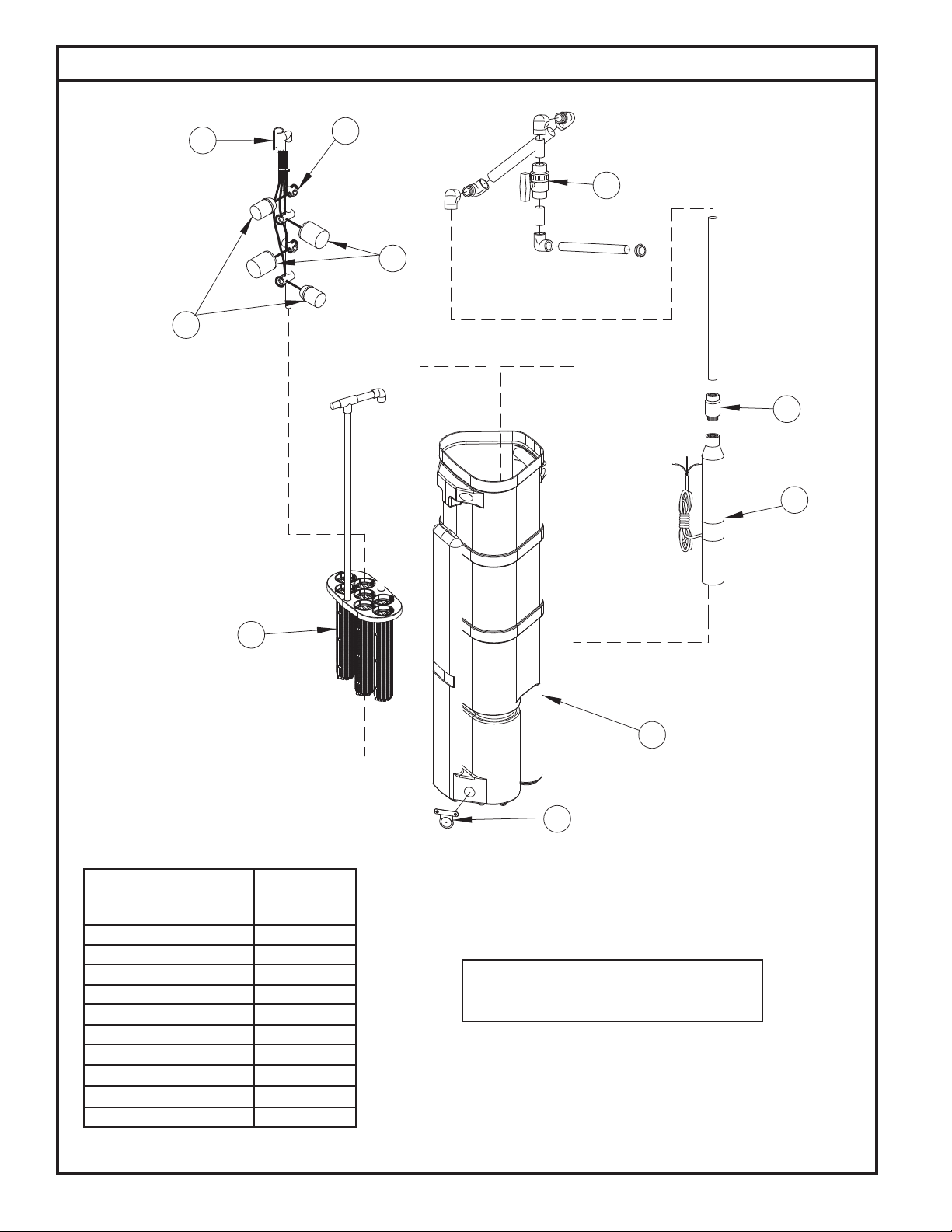
Replacement Parts for Clarus Environmental Turbine STEP System
3
4
6
5
2
7
8
1
SERVICE PARTS LIST TURBINE
EFFLUENT STEP SYSTEM
PART NUMBER
PART NAME 4/04 THRU
CURRENT
1 FILTER ASSEMBLY 016140
2 FLOAT (NARROW ANGLE) 011833
3 FLOAT TREE (TEE ONLY) 10-1681
4 FLOAT HOLDER 013940
5 FLOAT (WIDE ANGLE) 004066
6 DISCHARGE ASSEMBLY 170-0082
7 EXTERNAL CHECK VALVE 30-0187
8 PUMP consult factory
9 PUMP TANK* 016452
10 FLAPPER ASSEMBLY 016141
9
10
The accompanying parts list is provided for ordering
service parts. Please have pump model number and
date code ready for immediate service.
SK2417
*NOTE: Replacement tank will require eld cutting of the inlet.
© Copyright 2011. All rights reserved.
10

Covered by US Patent No.
5,985,139; others pending.
)
J-BOX
RISERS FOR DRAINAGE
SLOPE GROUND AWAY FROM
REMOVAL OF THE FILTER ASSEMBLY.
(INSTALL THE J-BOX IN SUCH A MANNER
THAT IT WILL NOT INTERFERE WITH THE
DISCHARGE PIPE ASSEMBLY
(INCLUDES FLEXIBLE PVC PIPE, UNION,
CLARUS
24 OR 30 INCH ACCESS RISER & LID
SECURE EXCESS CORDAGE
(FOR FILTER REMOVAL)
CLARUS
& LID
CLARUS
24" RISER
BALL VALVE, AND PIPE SEAL)
FILTERED EFFLUENT
TOP OF FILTER TANK
11"
TOP OF FLOAT TREE
ALARM
15"
25"
ON
CUT TO
51"
OFF
3 1/2 MIN.
TOP OF FILTERS
(SEE NOTE)
TOP OF INLET
* * * * * * *
17 1/8"
STATE OR LOCAL CODES
WITH NEC AND ANY OTHER
ALL WORK IN ACCORDANCE
* * * * * * *
* * * * * * * * * * * * * * * * * * * * * * * * *
126"
* * * * * * * * * * * * * * * * * * * * * * * * *
SK2422
CLARUS
(MOUNTED ON HOUSE)
INDOOR/OUTDOOR ALARM
ENGINEERED SYSTEMS
CONTROL PANEL
CLARUS
PERMANENTLY MOUNTED
HAZARD
ELECTRICAL SHOCK
WARNING
!
REV. A
P/N 10-1193
CONDUIT
18" MIN. OR
PER STATE AND
PREWIRED
CLARUS
SLOPE GROUND AWAY FROM
RISERS FOR DRAINAGE
FILTERED EFFLUENT
FLEXIBLE DISCHARGE ASSEMBLY
8"
48"
LOCAL CODES
TIMER OVERRIDE
HIGH WATER ALARM
INLET
JOB SPECIFIC
SECURE EXCESS CORDAGE
(FOR FILTER REMOVAL)
5"
REDUNDANT OFF
LOW LEVEL CUTOUT
(TO BE DETERMINED BY ENGINEER)
5"
TOP OF INLET
(SEE NOTE)
3 1/2"
MIN.
THE INLET HOLE ON ENGINEERED FILTER TANKS ARE FIELD INSTALLED.
NOTES:
ENGINEERED FILTERED STEP SYSTEM
INLET HEIGHT TO BE DETERMINED BY ENGINEER, APPROXIMATELY 40%
BELOW THE EFFLUENT SURFACE.
(SINGLE OR DUAL PUMPS)
DUAL PUMP SHOWN
NON HANGING CUSTOM TANK AVAILABLE IN 51".
HANGING CUSTOM TANKS AVAILABLE IN 60", 66", 72", 84", 90" AND 96".
17 3/8
30 INCH RISER & LID
CLARUS
© Copyright 2011. All rights reserved.
4 1/2"
FILTERED EFFLUENT
91 1/2
SINGLE INLET
CUT 2" X 5"
INLET TUBE
HOLE TO BE
11

Notes
All Clarus Environmental products must be installed and maintained in accordance with all applicable codes.
Product information presented here reects conditions at time of publication. Consult factory regarding discrepancies or inconsistencies.
Your Peace of Mind is Our Top Priority
3649 Cane Run Rd. • Louisville, KY 40211-1961 • 877-244-9340 • FAX: 877-414-4316
www.clarusenvironmental.com
© Copyright 2011. All rights reserved.
®
 Loading...