

Page 1
CAUTION
®
®
3649 Cane Run Road • Louisville, KY 40211-1961
800-928-7867 • Fax: 502-774-3624
www.clarusenvironmental.com
SECTION: C4.00.121
CL0162
0814
Supersedes
New
6000 Series Automatic Multizone Valve
OWNER'S MANUAL
Congratulations on the purchase of the Clarus Environmental
6000 Series Automatic Multizone Valve. High quality workmanship
and easy maintenance design has been incorporated into this line
of onsite wastewater products. This Clarus Environmental product
will provide years of trouble-free service when installed according
to the manufacturers recommendations.
Table of Contents
Safety Instructions .......................................................................... 1
Limited Warranty.............................................................................2
Major Components ......................................................................... 2
Cam Replacement Instructions ...................................................... 2
Valve Installation Instructions ........................................................2
Technical Specications ................................................................. 3
Parts List ......................................................................................... 3
Troubleshooting and Service Checklist .........................................4
This manual incorporates the installation, operation, maintenance,
and service instructions into one document to aid the owner of a Clarus
Environmental onsite wastewater product. Please read and review this
manual before installing the product. The instructions contained herein,
when followed correctly, will not only ensure a long and problem-free
life for the system, but will also save time and money during installation.
Should further assistance be necessary please call 1-800-928-7867.
Safety Instructions
TO AVOID SERIOUS OR FATAL PERSONAL INJURY OR MAJOR
PROPERTY DAMAGE, READ AND FOLLOW ALL SAFETY
INSTRUCTIONS IN MANUAL AND ON VALVE.
THIS MANUAL IS INTENDED TO ASSIST IN THE INSTALLATION
AND OPERATION OF THIS UNIT AND MUST BE KEPT WITH
THE VALVE.
This is a SAFETY ALERT SYMBOL.
When you see this symbol on the valve or in the
manual, look for one of the following signal words
and be alert to the potential for personal injury or
property damage.
Owner’s Information
Part Number: ______________ Date Code: _________
Job Name: ______________________________________
Dealer: _________________________________________
Date of Purchase: ________________________________
Contractor: ______________________________________
Date of Installation: ______________________________
System Readings During Operation:
Voltage __________ Amps _________
© Copyright 2014. All rights reserved.
Warns of hazards that WILL cause serious personal
injury, death or major property damage.
Warns of hazards that CAN cause serious personal
injury, death or major property damage.
Warns of hazards that CAN cause personal injury
or property damage.
Indicates special instructions which are very
important and must be followed.
THOROUGHLY REVIEW ALL INSTRUCTIONS AND WARNINGS
PRIOR TO PERFORMING ANY WORK ON THIS VALVE.
MAINTAIN ALL SAFETY DECALS.
Page 2
Limited Warranty
Manufacturer warrants, to the purchaser and subsequent owner during
the warranty period, every new product to be free from defects in material
and workmanship under normal use and service, when properly used and
maintained, for a period of one year from date of purchase by the end user, or
18 months from date of original manufacture of the product, whichever comes
rst. Parts that fail within the warranty period, one year from date of purchase
by the end user, or 18 months from the date of original manufacture of the
product, whichever comes rst, that inspections determine to be defective
in material or workmanship, will be repaired, replaced or remanufactured
at manufacturer's option, provided however, that by so doing we will not be
obligated to replace an entire assembly, the entire mechanism or the complete
unit. No allowance will be made for shipping charges, damages, labor or
other charges that may occur due to product failure, repair or replacement.
This warranty does not apply to and there shall be no warranty for any
material or product that has been disassembled without prior approval
of manufacturer, subjected to misuse, misapplication, neglect, alteration,
accident or act of God; that has not been installed, operated or maintained
in accordance with manufacturer's installation instructions; that has been
exposed to outside substances including but not limited to the following:
sand, gravel, cement, mud, tar, hydrocarbons, hydrocarbon derivatives (oil,
gasoline, solvents, etc.), or other abrasive or corrosive substances, wash
towels or feminine sanitary products, etc. in all applications other than in
raw efuent pumping applications. The warranty set out in the paragraph
above is in lieu of all other warranties expressed or implied; and we do not
authorize any representative or other person to assume for us any other
liability in connection with our products.
Contact manufacturer at, 3649 Cane Run Road, Louisville, Kentucky 40211,
Attention: Customer Service Department to obtain any needed repair or
replacement of part(s) or additional information pertaining to our warranty.
MANUFACTURER EXPRESSLY DISCLAIMS LIABILITY FOR SPECIAL,
CONSEQUENTIAL OR INCIDENTAL DAMAGES OR BREACH
OF EXPRESSED OR IMPLIED WARRANTY; AND ANY IMPLIED
WARRANTY OF FITNESS FOR A PARTICULAR PURPOSE AND OF
MERCHANTABILITY SHALL BE LIMITED TO THE DURATION OF THE
EXPRESSED WARRANTY.
Some states do not allow limitations on the duration of an implied warranty,
so the above limitation may not apply to you. Some states do not allow
the exclusion or limitation of incidental or consequential damages, so the
above limitation or exclusion may not apply to you.
This warranty gives you specic legal rights and you may also have other
rights which vary from state to state.
Major Components
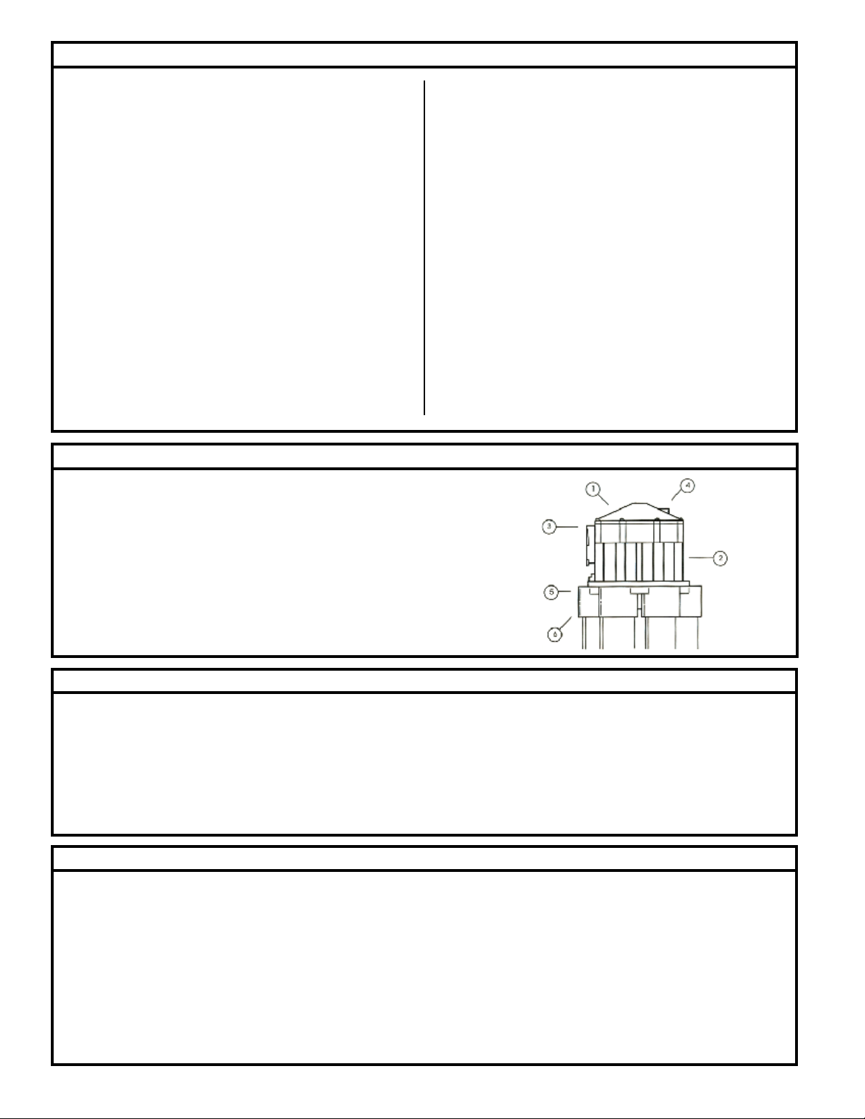
1. Valve Top: A high strength metal die cast top which is secured to the valve body by eight
stainless steel screws.
2. Valve Body: A high strength metal die cast housing.
3. Inlet: Female 1 ½" NPT inlet for connection to water source.
4. Vacuum Breaker Port: Used to prevent back-siphon of water to course.
5. Valve Bottom: High strength ABS plastic bottom which is secured to a valve body with 6
stainless steel screws.
6. Outlets - Allows for slip and glue connection to 1 ½" PVC pipe.
Cam Replacement Instructions
Replacement cams are available to increase or decrease the number of outlets to be used on the 6000 Series Automatic Multizone Valve. 6400 Series four
outlet valves have interchangeable cams for two, three or four zone operation. 6600 Series six outlet valves have interchangeable cams for ve or six zone
operation.
To replace cam, rst remove valve top by removing eight valve top retaining screws. Remove two cam retaining screws which hold cam on the underside of
the valve top.
Insert replacement cam into valve top, ensuring that the wide notch on came is aligned with notch on valve top, and secure with two cam retaining screws.
Replace top, ensuring body seal is in place.
Valve Installation Instructions
Prior to installation of 6000 Series Automatic Multizone Valve, make sure that the system is designed using adequate pipe sizes and control valves to
ensure maximum performance of the valve.
For installation with large terrain elevations, or applications with high lift requirements such as overhead systems in greenhouses, the valve should be
installed at the highest point in the system, or check-valves should be installed near the valve in the elevated lines to prevent the back ow of water from
the higher locations to the lower zones.
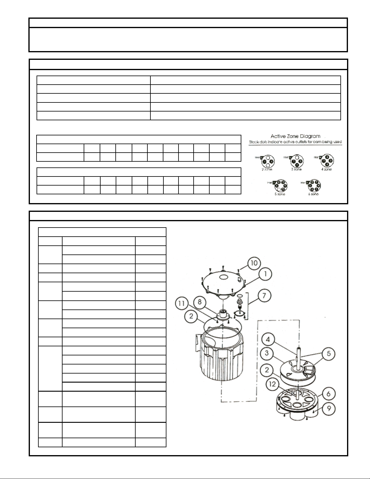
When connecting the lines to the valve outlets, ensure that the correct cam is installed. See diagram for proper zone hookup of outlets.
Do NOT turn the valve upside down when gluing the lines into the open valve outlets. Glue may run down into the valve and interfere with valve operation.
Allow glue to dry for at least two hours before operating or testing the valve. For best results, use a multipurpose glue which is compatible with ABS plastic.
To seal off any unused outlets, install a piece of PVC pipe at least six inches in length to the outlet and cap the pipe. This will allow additional zones to be
added easily at a later time. Make sure proper cam is installed for number of zones to be used.
© Copyright 2014. All rights reserved.
2
Page 3
Pump Fed Application
For direct pump-fed installations, the 6000 Series Automatic Multizone Valve is directly connected to the discharge side of the pump and is cycled from
one zone to the next by turning the pump off and on. See the Active Zone Diagram below in Figure 1.
Technical Specications
Valve Top and Body Construction: Die cast
Valve Bottom Construction: ABS High strength plastic
Flow Range: 15-100 GPM
Inlet: Threaded 1½" NPT
Outlets: Allows for 1½" PVC pipe slip and glue connection
Flow Characteristics:
6400 Series 4 Outlet Valve
Flow (GPM) 15 20 30 40 50 60 70 80 90 100
PSI Loss 2.0 2.5 3.0 3.5 4.0 5.0 6.0 7.5 9.0 10.0
6600 Series 6 Outlet Valve
Flow (GPM) 15 20 30 40 50 60 70 80 90 100
PSI Loss 2.0 3.0 3.5 4.0 5.0 6.0 7.5 9.0 10.0 11.0
Parts List
Parts List
REF NO. DESCRIPTION PART NO.
4 Outlet valve top 153295
1
6 Outlet valve top 153296
2 Valve body seal 150495
3 Rubber ap disc 153268
Stem with .032 spring 153269
4
Stem with .028 spring 153270
Stem / disk assy. w/ .032 spring 019141
5
Stem / disk assy. w/ .028 spring 019142
4 Outlet valve bottom 153271
6
6 Outlet valve bottom 153272
7 Vacuum Breaker assy. 151258
Two zone, 4 outlet cam 019136
Three zone, 4 outlet cam 019137
Four zone, 4 outlet cam 019138
8
Five zone, 6 outlet cam 019139
Six zone, 6 outlet cam 019140
Valve bottom screws (6) (10-24 x
9
3/4 Phil Pan SS
Valve top screws (8) (10-24 x 5/8
10
Stlt.phst SS
Cam retaining screws (2) (6 x 1/2
11
Phil Pan SS)
12 Valve bottom S.S Pin (¼" dia.) 153073
153273
153274
153275
Figure 1
© Copyright 2014. All rights reserved.
3
Page 4
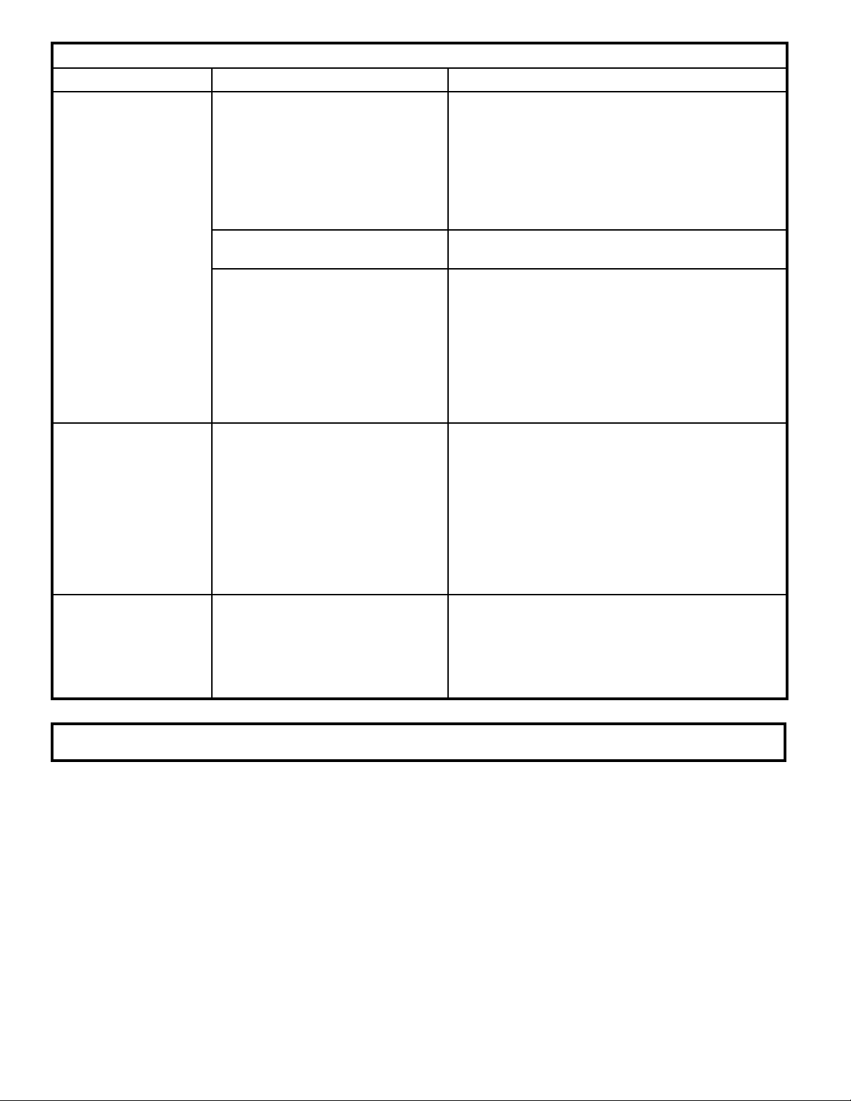
Problem Cause Solution
Valve does not change
or cycle to next zone or
outlet.
Water comes out of all
the valve outlets.
Valve skips outlets or
zones.
Troubleshooting and Service Checklist
Debris or foreign objects preventing
proper movement of stem and disk
assembly.
Disk may have expanded and is rubbing against inside walls of body.
Restriction of ow causing pressure
in valve to build up, preventing valve
from cycling.
Stem and disk assembly not seating
properly on valve outlet.
This will case the valve to cycle
quickly several times, skipping one
or more zones.
• Remove valve top and check for foreign objects.
Clean build-up from walls as necessary.
• Check for freedom of movement of stem and
disk assembly up and down over the center pin
in bottom of valve. Scale deposits may build up
on the pin and hold stem and disk assembly
down. Clean pin and again check for freedom of
movement.
• Replace disk and clean build-up from walls of
valve as necessary.
• Be sure that all operating outlets are not capped
and that the ow to operating zones is not
restricted in any manner.
• The backow of water from uphill lines may be
preventing the valve from cycling properly. If the
valve cannot be placed close to the high point
of the system, a check valve should be installed
near the valve in the outlet line that runs uphill
from the valve.
• Check for sufcient water ow. A minimum of 15
GPM is required to properly seat the disk.
• Remove the valve top and clean the inside walls
as necessary to ensure that nothing is interfering
with the up and down movement of the stem and
disk assembly inside the valve.
• Make sure that the operating outlets are no
capped and that the ow to the operating zones
is not restricted in any manner.
• Replace disk if necessary.
• The stem and disk assembly is being advanced
past the desired outlet.
• Ensure that the correct cam for the desired
number of zones is installed and that the outlet
lines are installed to the correct outlet ports of
the valve.
All Clarus Environmental products must be installed and maintained in accordance with all applicable codes.
Product information presented here reects conditions at time of publication. Consult factory regarding discrepancies or inconsistencies.
Your Peace of Mind is Our Top Priority
3649 Cane Run Rd. • Louisville, KY 40211-1961 • (800) 928-7867 • FAX: (502) 774-3624
www.clarusenvironmental.com
© Copyright 2014. All rights reserved.
4
®
 Loading...