

Page 1
®
®
3649 Cane Run Road . Louisville, KY 40211-1961
877-244-9340 . Fax: 877-414-4316
www.clarusenvironmental.com
Fusion® Series Treatment Systems
OWNER'S MANUAL
Thank you for choosing a Fusion® Series Treatment System. High quality
workmanship and easy maintenance have been incorporated into the
Fusion® system. The system will provide years of trouble-free service
when maintained according to the manufacturer’s recommendations.
Please read this manual in its entirety before using the Fusion®, and
follow all instructions to ensure proper operation. Keep this manual for
future reference along with other important onsite documents. Should
further assistance be necessary, please contact Clarus Environmental
at 1-877-244-9340.
Warning Labels
You will nd warning labels on the Fusion®, riser lids, blower, and the
alarm control panel. It is very important to follow the information on
these labels to ensure your safety. Please do not remove these labels.
SEE LIST AT RIGHT FOR WARNINGS
SECTION: C3.10.140
CL0056
0612
Supersedes
New
1. DO NOT attempt to service the Fusion
authorized maintenance provider for all service related issues.
2. There are buried electrical cables and piping near and around the
Fusion®. Please consult your authorized maintenance provider to
locate these utilities before excavation.
3. DO NOT bury or cover the Fusion® lids with soil or other debris.
This is necessary to allow access for operation and maintenance
of the unit.
4. The Fusion® blower must be unobstructed and vented for
proper operation. Care must be taken that no grass clippings or
other materials accumulate on or around the blower and block
ventilation.
5. DO NOT place heavy objects over the Fusion® or drive heavy
equipment over the Fusion®, as damage may occur. Damage of
this kind is not covered by the warranty.
6. DO NOT plant trees within 15 feet (4.6 m) of the Fusion
Treatment System.
®
unit yourself. Contact your
®
Series
TABLE OF CONTENTS
Limited Warranty ......................................1
Process Description.................................... 3
System Components and Care ...........................4
Excavation and Installation .............................. 6
Start Up . . . . . . . . . . . . . . . . . . . . . . . . . . . . . . . . . . . . . . . . . . . . . . 9
Blower Timer Setting .................................. 11
Operation and Maintenance ............................12
Aeration Chamber Cleaning ............................14
Fusion® Pumping . . . . . . . . . . . . . . . . . . . . . . . . . . . . . . . . . . . . . 15
Troubleshooting ...................................... 16
LIMITED WARRANTY
Manufacturer warrants, to the purchaser and subsequent owner during
the warranty period, every new product to be free from defects in material
and workmanship under normal use and service, when properly used and
maintained, for a period of two years from date of purchase by the end
user. No allowance will be made for shipping charges, damages, labor or
other charges that may occur due to product failure, repair or replacement.
This warranty does not apply to and there shall be no warranty for any
material or product that has been disassembled without prior approval of
Manufacturer, subjected to misuse, misapplication, neglect, alteration,
accident or act of God; that has not been installed, operated or maintained
in accordance with Manufacturer's installation instructions; that has been
exposed to outside substances including but not limited to the following:
sand, gravel, cement, mud, tar, hydrocarbons, hydrocarbon derivatives (oil,
gasoline, solvents, etc.), or other abrasive or corrosive substances, wash
towels or feminine sanitary products, etc. in all pumping applications. The
warranty set out in the paragraph above is in lieu of all other warranties
expressed or implied; and we do not authorize any representative or other
person to assume for us any other liability in connection with our products.
The Fusion® Series Treatment Systems represent a collaboration with Fuji Clean Co., Ltd.
© Copyright 2012. All rights reserved.
Fusion® Model: ZF-450 ZF-600 ZF-800
Serial No. ____________________________________
Installing Contractor ____________________________________
Phone Number ____________________________________
Installation Date ____________________________________
Maintenance Provider’s Name _____________________________
Phone Number ____________________________________
Contact Manufacturer at, 3649 Cane Run Road, Louisville, Kentucky 40211,
Attention: Customer Support Department to obtain any needed repair or
replacement of part(s) or additional information pertaining to our warranty.
MANUFACTURER EXPRESSLY DISCLAIMS LIABILITY FOR
SPECIAL, CONSEQUENTIAL OR INCIDENTAL DAMAGES OR
BREACH OF EXPRESSED OR IMPLIED WARRANTY; AND ANY
IMPLIED WARRANTY OF FITNESS FOR A PARTICULAR PURPOSE
AND OF MERCHANTABILITY SHALL BE LIMITED TO THE DURATION
OF THE EXPRESSED WARRANTY.
Some states do not allow limitations on the duration of an implied warranty,
so the above limitation may not apply to you. Some states do not allow
the exclusion or limitation of incidental or consequential damages, so the
above limitation or exclusion may not apply to you.
This warranty gives you specic legal rights and you may also have other
rights which vary from state to state.
Page 2
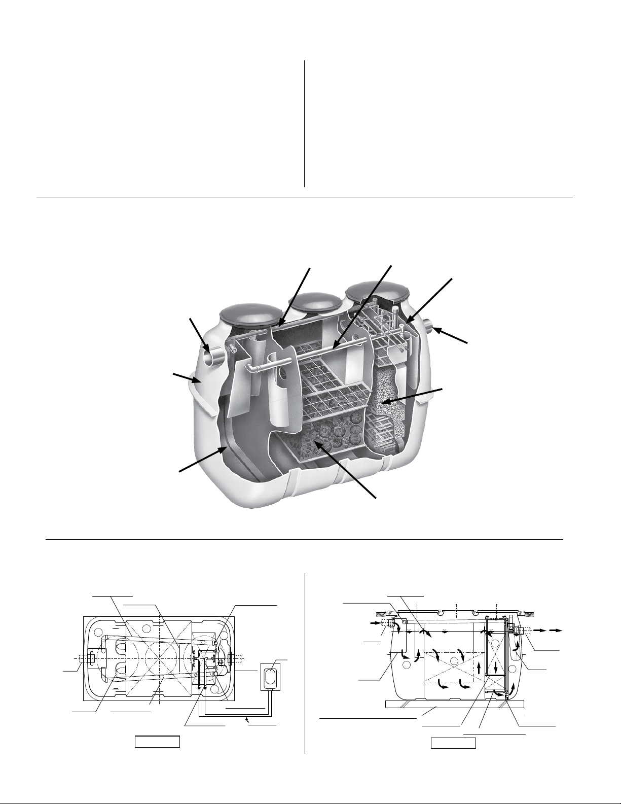
HOW A FUSION® SERIES TREATMENT SYSTEM WORKS
The Fusion® is simple in design, yet advanced in its wastewater
treatment ability. The design has been rened over many years
of intense research and development in an effort to perfect
this superior treatment system. Fusion
®
systems are 90% -
95% efcient at treating wastewater. This is nearly twice as
effective as a traditional septic tank, which is approximately
50% efcient. This high degree of treatment helps to protect
both your personal property and the environment.
The Fusion
oxygen) and aerobic (with oxygen) biological processes to treat
wastewater. As wastewater enters the Fusion
Figure 1 - The following diagram will help you to better understand the process:
®
utilizes a combination of anaerobic (without
®
, it is broken
down and becomes food for biological organisms operating
within the unit. The rst chamber serves to separate grease
and large solids from the liquid. In the second chamber, plastic
media with large surface areas are used to increase contact
between water and benecial bacteria to optimize treatment. A
small linear air blower is used to move air (oxygen) into the third
chamber for the aerobic process. The nal efuent leaving the
system will have been treated to secondary quality efuent and
will average *9 mg/L CBOD5 and 9mg/L TSS.
* Based on NSF Standard 40 testing.
Recirculation Line
Inlet Pipe
4” PVC
SCH 40 (DN 100)
Sludge Return Line
Storage
Chamber
Outlet Pipe
4” PVC
SCH 40
(DN 100)
Tank - Compression
Molded Fiber
Reinforced Plastic
Sedimentation
Chamber -
Separates bulk solid
and grease waste
Figure 2 - Schematic diagram of the Fusion
Re-circulation
Inflow
Baffle
1
Sludge return
Baffle
2
Backwash
Top View
®
Treatment System
Air-lift Pump
4
Effluent
3
Air-lift Pump
Aeration
Blower
Anaerobic Chamber -
Organisms adhere to xed lm
media and digest waste
Recirculation
6 “ (152 mm) stone or concrete pad
Wall opening
G.L.
W.L
Inflow
1
Baffle
Aeration Chamber
Floating/Circulating
Filter Media -
“Fluidized Bed”
Invigorates aerobic bacteria
W.L
2
Recirculation
Side View
W.L
3
Backwash Mechanism
G.L.
Baffle
4
Wall opening
Effluent
© Copyright 2012. All rights reserved.
2
Page 3
P R E L I M I N A RY
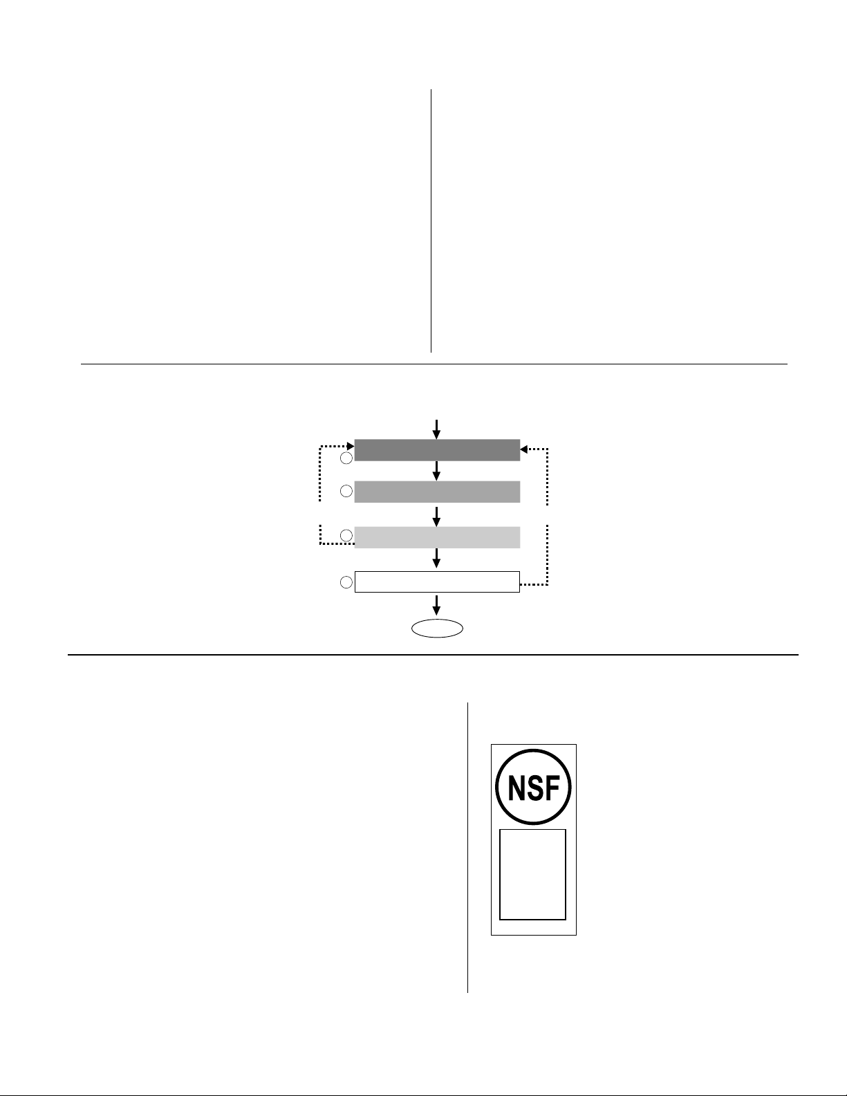
PROCESS DESCRIPTION
1. Sedimentation Chamber
This chamber is designed to physically separate solids
from the incoming water. Scum is the oating material
and sludge is the material that has settled at the bottom.
2. Anaerobic Chamber
This chamber contains a spherical skeleton-type lter
media, 4.3 inch diameter (109 mm). Through bacterial
growth processes on the surface of the lter media,
biological anaerobic treatment thrives while suspended
solids are captured. Furthermore, the microorganisms
in this chamber convert nitrates in the recirculated water
returning from the aerobic chamber to gaseous nitrogen.
The gaseous nitrogen then escapes to the atmosphere.
3. Aeration Chamber
The aeration chamber consists of an aerated upper
section and a lter media lower section. The chamber is
lled with hollow, cylindrical lter media 0.6 inch diameter
Figure 3 - Treatment Flow of the Fusion® System.
1
2
Back-Wash
3
(15 mm) and 0.55 inches long (14 mm). Biological
treatment takes place on the lter media surface.
Aeration is continuous. Residual suspended solids are
captured by the lter media circulating in this section.
During normal operation, a recirculation line transfers
water back to the sedimentation chamber by way of an air
lift pump.
The lter media in the aeration chamber are backwashed
regularly (twice a day, 5 or 10 minute cycle) by the
backwash system located at the bottom of the chamber.
The accumulated sludge is transferred by an air lift pump
back into the sedimentation chamber for further digestion.
4. Storage Chamber
This chamber is designed to temporarily store treated
water exiting the aeration chamber. This treated water is
ready for discharge.
Inflow
Sedimentation Chamber
Anaerobic Chamber
Recirculation
Aeration Chamber
4
Storage Chamber
Effluent
SYSTEM COMPONENTS
The complete wastewater treatment system will typically consist of
the Fusion
disposal of the liquid efuent. Some states or counties may require
the addition of a septic tank before the Fusion® to increase the
sedimentation chamber capacity and retain more solids. Please see
Figure 11 for a typical Fusion
will be made to suit your particular site and system design needs.
Please contact your authorized Fusion® installer or maintenance
provider for further information about your system design.
The Fusion® treatment unit comes with an electronic, dual-
port blower designed specically for use with this system. The
blower utilizes a linear motor and two diaphragms to generate
the air ow necessary to aerate and recirculate water within the
system. This style of compressor is quieter and more efcient
than traditional rotary vane compressors. Once installed and
adjusted, circuitry within the blower will automatically switch the
unit from normal recirculation mode to backwash mode and back
again when appropriate. In the event of a power outage, the
blower will stop, but a backup battery within the unit will retain
the correct time and backwash settings.
®
treatment components and a soil absorption eld for nal
®
system. Variations to the typical system
®
THE FUSION
DUAL-PORT BLOWER
© Copyright 2012. All rights reserved.
3
Figure 4
Certified to
NSF/ANSI
Standard 40
Class 1
Performance
Designation
NSF STANDARD 40, CLASS 1,
CERTIFICATION MARK
The NSF mark displayed here
will be on all NSF Standard
®
40, Class 1 certied Fusion
systems. The Fusion
ZF-450, ZF-600 and ZF-800 will
have the mark displayed on the
alarm panel. Systems not NSF
Standard 40, Class 1 certied,
will not display the mark.
®
models
®
Page 4
DATAPLATE
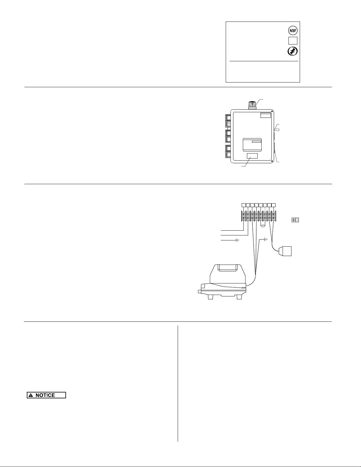
A dataplate similar to the one in Figure 5 is located on the blower
housing and the alarm panel. There is important information about
the Fusion
number, serial number, and hydraulic capacity. Please make a
note of this information for future reference or in case you should
need to contact your Fusion® maintenance provider.
The contracting installer must mark the installed model number
on the dataplate, the blower housing and the alarm control panel.
®
on the dataplate, such as the part number, model
Figure 5
FU SI ON T REA TMEN T SYS TEM
□
ZF 450
ZF 600
□
ZF 800
□
MFG.DATE: 09/07
Manufacturer:
BL OWE R SER VI CE P AR TS
P/N 018860-B
450
GALLONS/DAY
600GALLONS /DAY
800GALLONS /DAY
Clarus Environmental • 3649 Cane Run Road
Louisville, KY 40211•1-877-244-9340
COMPLETE BLOWER: P/N 019617
BLOWER DIAPHRAGM: P /N 018848
BLOWER FILTER: P/N 018849
toll free
Certified to
NSF - ANSI
Standard 40
®
®
ALARM PANEL
The Fusion® comes with an alarm panel (see Figure 6) that is
designed to activate an audible buzzer and red beacon light on
top of the panel if there is a drop in air pressure, if a high water
alarm condition occurs, or if the blower does not cycle between
recirculation and backwash modes within the preset time. (Note:
Alarm panel can only function as long as there is electrical power
supplied to the panel)
You may from time to time check the proper operation of the
alarm panel by toggling the black switch on the side of the panel
to “test”. The buzzer will sound and the red beacon will light as
long as you hold the switch in the test position. Release the
switch for normal operation.
SYSTEM CARE
®
The Fusion
with little direct maintenance from the owner. Periodically, a check of the
blower area is recommended to ensure no debris obstructs the ventilation
or intake areas of the blower. Also, periodically test the control panel
as outlined under the alarm panel section. The owner should closely
monitor the types and amounts of substances and products used. Water
use should also be closely monitored to ensure proper operation of the
Fusion® system.
Periodically, more extensive maintenance must be performed. Your
authorized Fusion® maintenance provider will oversee this service. The
name of the maintenance provider can be recorded on the front of this
document and should also be located on the alarm panel. For more
information see the Operation and Maintenance section of the manual.
The owner should only perform minimal routine maintenance on the Fusion®
such as clearing debris from around blower housing (leaves, snow, and
grass clippings). The Fusion® should also be protected from excessive
weight such as vehicular trafc. Trees and bushes should not be planted
in close proximity to the Fusion®. The Fusion® should be accessible to
maintenance personnel and the riser lids must never be buried.
system is designed to continuously operate automatically
Figure 6
Figure 7
120 VAC
INCOMING
POWER
L1
N
GND
BLOWER
FUSION
DATAPLATE
TB2
RED BEACON
WARNING!
SILENCE/TEST
SWITCH
P/N
BUZZER
1
2 3 4 5 6 7 8
DISNF
ALARM
HIGH WATER
*FOR ILLUSTRATION PURPOSES ONLY*
REFER TO SCHEMATIC LOCATED IN
PANEL FOR INSTALLATION
sk2649
GND LUG
ALARM
sk2933
HIGH USE WATER DEVICES
The draining of hot tubs and swimming pools into your Fusion® system
could cause hydraulic overloading and may reduce the treatment
efciency. Please drain these devices to another location. Contact
your local regulatory authorities or authorized Fusion® maintenance
provider for more information. The use of large capacity single ll and
drain whirlpool bathtubs may also cause hydraulic overloading of your
Fusion®. Please limit the use of these types of tubs.
FLOODING
If ooding of the Fusion® occurs and the blower
or the alarm panel is submerged, please disconnect power at the
circuit breaker. DO NOT try to reconnect power to either the blower
or alarm panel once it has been submerged. Immediately contact your
authorized Fusion® maintenance provider to inspect the Fusion®, the
blower, and the alarm panel. Your maintenance provider will repair or
replace the components as needed.
© Copyright 2012. All rights reserved.
LEAKY FIXTURES
It is very important to monitor all water xtures in the home for leaks
and drips and repair them immediately. Leaks can cause tremendous
water use and use may hydraulically overload your Fusion® system and
reduce its treatment efciency. Excessive water use may also overload
your soil absorption eld and cause failure.
INTERMITTENT USE
The Fusion® system is designed to function even if wastewater does
not enter it for extended periods of time. The power to the blower
must remain on during this time for the system to function properly.
Weekend use will not harm the system as long as the blower is on.
Should seasonal use require a complete shut down of the property,
then it is recommended that the blower be turned off. It is important
to start up the system in advance of actual occupancy to allow for
normal treatment to resume. Please contact your authorized Fusion®
maintenance provider for further information concerning shut down and
startup of the Fusion®. You may also contact your maintenance provider
for the shut down and startup services.
4
Page 5

P R E L I M I N A RY
HARMFUL SUBSTANCES
The Fusion® is designed to treat household type waste and
can treat most common substances introduced into the
system. However, certain harmful substances may reduce
the efciency or stop the treatment process by reducing or
destroying the benecial bacterial populations responsible for
treatment. In general, if a chemical substance is considered
harmful to humans then it should also be considered harmful
to the Fusion
concerning the use of any of these substances, please contact
your Fusion
substance on the “Do Not List” into the Fusion
the warranty.
DO NOT introduce the following substances into the
Fusion
• Motor oil • Antifreeze
• Brake uid • Paint
• Paint thinner • Gasoline
• Solvents • Pesticides
• Herbicides • Strong disinfectants
• Strong caustic drain • Toilet tank
cleaners in excess disinfection chemicals
• Excess pharmeceuticals • Chemicals & chemical
waste
Not Recommended: Trash and excess food products will
likely increase frequency of pumping.
Trash
• Sanitary napkins and • Condoms
feminine products • Cat litter
• Diapers • Dental oss
• Paper products such as • Cigarette butts
paper towels & baby wipes • Plastic/rubber products
Food Products
• Coffee lters and grounds • Greases or lards
• Fruit and vegetable peels • Seeds
• Meat products • Bones
• Garbage disposal waste • Egg shells
Limited Use Products
Certain products in small or moderate amounts should not
disrupt the Fusion
the minimum quantities of these substances as recommended
by the manufacturer.
• Liquid laundry bleach only as needed per load
• Liquid laundry detergents without added bleach
• Liquid dishwashing detergents
• Household cleaners
®
treatment system. If you have any questions
®
maintenance provider. The introduction of any
- THE DO NOT LIST -
®
treatment system:
®
treatment process. You should always use
®
will void
EFFLUENT QUALITY
®
Fusion
be installed in a typical residential/light commercial environment.
The nal efuent leaving the system will typically be treated to the
secondary quality strength of *9 mg/L CBOD5 and 9 mg/L TSS.
*
If water softners are present in the home, Clarus Environmental
recommends the use of water and salt conservative models
that are installed and operated correctly. If you have questions
about softeners, contact the Water Quality Association at
www.wqa.org. Contact factory for installation details.
Series systems are compact, efcient, and designed to
Based on NSF/ANSI Standard 40 testing.
WATER SOFTENERS
© Copyright 2012. All rights reserved.
INITIAL SERVICE POLICY
The Fusion® models ZF-450, ZF-600, and ZF-800 (NSF
Standard 40, Class 1 certied systems) have a two-year service
policy included in the initial purchase price. The service policy will
include two inspections per year for a total of four inspections.
During these inspections, numerous system checks and
adjustments will be made to ensure proper operation.
EXTENDED MAINTENANCE POLICY
An extended maintenance policy is available for purchase from
your authorized Fusion
policy will include the same system checks, schedule, and
adjustments as the initial maintenance policy. Please contact
your Fusion
information regarding the extended maintenance policy.
®
distributor or maintenance provider for further
®
distributor. The extended maintenance
AUTHORIZED MAINTENANCE PROVIDER
Your authorized maintenance provider will perform many system
checks and adjustments as needed during the maintenance
inspection. Two inspections per year will be made for a total of four
inspections during the initial service policy. Please see the Operation
and Maintenance section of this manual for further details.
Should there be any operational deciencies with your Fusion
the maintenance provider will notify the owner in writing when the
deciencies will be corrected. If the maintenance provider does
not correct the deciencies or the service calls are not completed,
please contact Clarus Environmental at 1-877-244-9340.
INSPECTION AND MAINTENANCE FREQUENCY
Fusion® Series systems are to be inspected and maintained
every six months under normal usage. The inspection and
maintenance are only to be performed by personnel trained and
authorized by Clarus Environmental. A Maintenance & Service
Report (CL0059) is to be completed for each inspection and
maintenance visit.
ALARM CONDITION
If an alarm condition occurs, please check the air intake area
around the blower and make sure no debris blocks the blower
intake. Remove the air lter cap by removing the screw from
the cap and then pulling on the sides of the top of the blower.
Remove the foam lter and gently tap against your other hand.
If it is very clogged wash it in warm, soapy water and dry well
before replacing. Reassemble lter and cap on top of blower.
Do not attempt to remove the blower housing or any other
parts from the blower. If the blower is operating properly, there
may be a high water condition within the Fusion
necessary to discontinue water use until the alarm condition
has been resolved. If the buzzer continues to sound or the
red light stays on, please contact your authorized Fusion
maintenance provider. The buzzer may be silenced by toggling
the black switch on the side of the alarm panel to “silence”.
The red beacon light will remain on until the problem has been
resolved.
®
. It may be
POWER OUTAGE
Should you experience a power outage, the blower will not
operate and air (oxygen) will not be supplied to the Fusion
If the blower is off for more than 24 hours, the lack of fresh
air will cause the treatment efciency to decrease. During a
power outage, the Fusion
will not create a backup in the home. You may, however,
have a pump or dose tank with a pump on the outlet of the
®
Fusion
soil absorption eld. If you have a system such as this,
please be aware of this condition and conserve water
accordingly.
5
, which requires power to pump the efuent to the
®
will still allow efuent to ow, and
®
,
®
®
.
Page 6
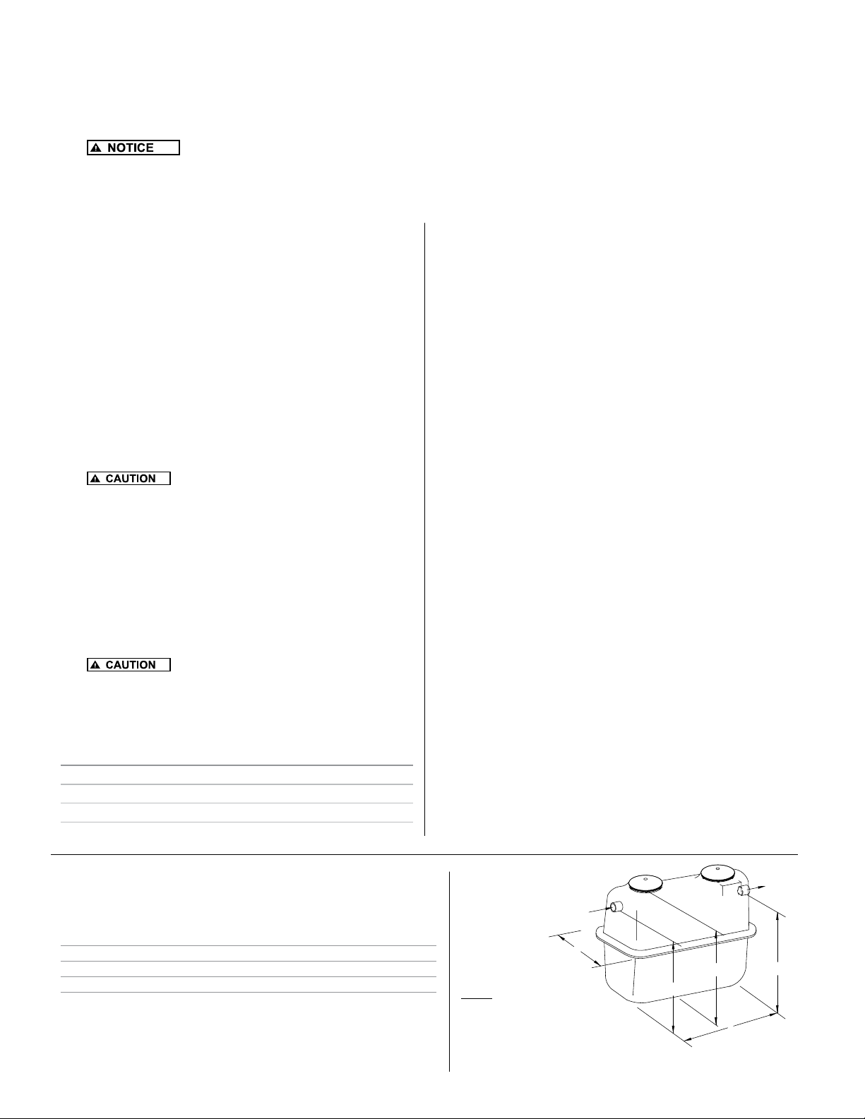
EXCAVATION AND INSTALLATION
1. Excavate an area large enough for the Fusion® Series unit to be installed. See Figure 8 and Table 3 for the actual dimensions
of the unit. Excavation dimensions are calculated by adding 12-18" (305-457 mm) to the length and width of the Fusion
will allow sufcient room for proper backlling.
2. Construct a 6" (152 mm) thick stone pad of either 1/4" - 1/2" (6-13 mm) diameter stone or concrete pad and level to within 1/8" (3 mm).
3.
If the unit is not level, it will cause uneven water ow as well as unbalanced aeration, which will result in
poor performance.
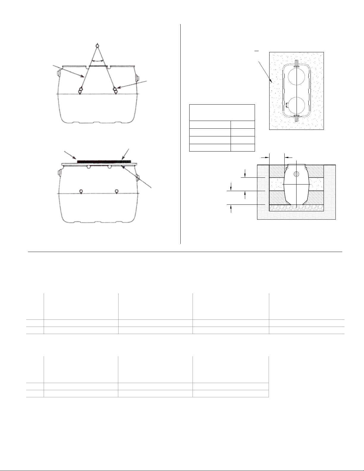
4. Gently lift the unit at all four lifting points with a harness and install it on leveled stone pad (Figure 9).
5. Check unit to make certain it is level by placing a level at several locations on the riser. (riser covers removed) (Figure 9).
®
. This
BACKFILLING
1. If groundwater is present, anti-otation measures must be
used to stabilize the unit prior to backlling. Please follow
the procedures in the Anti-otation section to properly
anchor the Fusion
2. Fill the unit with clean water to the normal operating depth
prior to backlling. Partition walls between chambers are
water-tight and will ll in succession beginning on the inlet
side of the unit. Therefore, it is best to alternate chambers
when lling with water so the unit remains level. Check for
leakage around the unit.
3. If necessary, install riser extensions on the adapter rings
prior to backlling. See Table 1 for number and size of
access opennings. Riser extensions are available for
deeper burial. Make certain risers are sealed properly and
watertight.
4. Apply two beads of silicone fully around
each riser section prior to securing with supplied screws.
5. Install riser covers.
6. Backll with good quality granular soil around the unit that is
free of organic matter, rock, stone, tree roots, or other debris
that could damage the unit.
7. Tamp soil around perimeter of the unit as it is backlled to
stabilize the unit and to reduce settling.
8. Finalize backll with a mounded contour so that surface
water is shed away from the unit. Under no circumstances
should surface water be allowed to accumulate around unit.
9.
is 36 inches (914 mm).
Table 1
Number aND size of access opeNiNgs iN fusioN
20" (51 cm) Diameter
24" (61 cm) Diameter
®.
MAXIMUM soil burial depth over the unit
®
series
ZF-450 ZF-600 ZF-800
0 1 1
2 2 2
COLD WEATHER INSTALLATION
When installing Fusion® in cold climates, the designer should
specify insulated lids and risers from the factory. These are
available as an option to the standard lids and risers. In addition,
the blower must be protected from snow drifts by installing it
either inside a garage, home, basement, crawlspace or riser. If
installed in a riser, the blower must be protected from inundation
and must have a vent pipe installed to above the maximum
snow depth with a 180 degree angle at the end to prevent snow
and water entry. Also, the top and sides of the Fusion
®
must be
insulated with insulation sheeting or other means to provide a
minimum insulation value of R-8. Please contact the factory for
further information.
ANTI-FLOTATION PROCEDURES
It is necessary to anchor the Fusion® in high ground water
conditions to prevent otation. If groundwater rises above the
rock or concrete pad that the Fusion
required. Please consult a design engineer, soil scientist or other
qualied individual to determine high groundwater conditions.
1. Follow the procedures outlined in the Excavation and
Installation Section items 1-5 to properly prepare and level
the Fusion excavation.
2. Follow the procedures outlined in the Backlling Section
items 1-4 to properly ll the Fusion
risers if needed.
3. Refer to Figure 10, Anchoring Schematic to determine
the minimum amount of backll to be placed around the
®
Fusion
in the excavation. Tamp the ll to prevent settling.
4. Refer to Table 3, Concrete Anchoring Dimensions to
determine the amount of concrete needed for the concrete
anchor collar that is poured around the entire circumference
of the Fusion
®
. Pour concrete to the specied dimensions
to fully engage the mid-seam of the Fusion
anchor it once the concrete cures. Make certain to pour
the concrete in a manor to minimize trapped air within
the concrete. Agitating or lightly mixing the concrete with
a metal rod or other similar device once poured will help
release trapped air.
5. Allow the concrete to harden before nal backlling.
6. Complete the procedures outlined in the Backlling Section,
items 5-8.
®
sits on, anchoring is
®
with water and add
®
, which will
Table 2
FUSION® DIMENSIONS
SYSTEM L W H I E
®
Fusion
450 7'-1" (2.2 m) 3'-8" (1.1 m) 5'-2" (1.6 m) 4'-4" (1.3 m) 3'-10" (1.2 m)
®
Fusion
600 8' (2.4 m) 4'-1" (1.2 m) 5'-6" (1.7 m) 4'-8" (1.4 m) 4'-2" (1.3 m)
®
Fusion
800 8'-3" (2.5 m) 4'-8" (1.4 m) 6'-2" (1.9 m) 5'-4" (1.6 m) 4'-10" (1.5 m)
© Copyright 2012. All rights reserved.
Figure 8- Dimensions
INLET
W
H
NOTES:
1) DIMENSIONS "I" AND "E" ARE TO THE BOTTOM
OF THE INLET/OUTLET PIPE.
2) THE OVERALL HEIGHT DIMENSION "H" IS TO THE
TOP OF THE NARROW ADAPTER RING, NOT THE RISER LID.
3) A RISER COVER COMES STANDARD. ADDITIONAL RISERS ARE
PURCHASED SEPERATELY.
6
I
OUTLET
E
sk2624
L
Page 7
P R E L I M I N A RY
Figure 9, Lifting & Positioning
4-POINT
LIFTING
LEVEL ACROSS TOP OF UNIT
LESS THAN 60°
LIFTING
60°
LIFTING
HOOK
Figure 10, Concrete Anchoring
CONCRETE ANCHOR
COLLAR
MIN. REQUIRED
BACKFILL
UNIT SIZE Z
ZF-450
ZF-600
ZF-800
18"
19"
21"
W
ADAPTER
RING
LEVELING
Table 2 - Concrete Anchoring Dimensions
H
Z
sk2931
Model No Cover 6" Cover 12" Cover 18" Cover
W H CoNCrete voluMe W H CoNCrete voluMe W H CoNCrete voluMe W H CoNCrete voluMe
(ft) (ft) (ft3) (CY) (ft) (ft) (ft3) (CY) (ft) (ft) (ft3) (CY) (ft) (ft) (ft3) (CY)
ZF-450 1' - 4" 2' - 0" 72 3 1' - 2" 2' - 0" 62 3 1' - 1" 2' - 0" 56 3 1' - 0" 2' - 0" 51 2
ZF-600 1' - 6" 2' - 0" 91 3 1' - 4" 2' - 0" 79 3 1' - 3" 2' - 0" 73 3 1' - 2" 2' - 0" 68 3
ZF-800 1' - 8" 2' - 0" 109 4 1' - 7" 2' - 0" 102 4 1' - 5" 2' - 0" 90 4 1' - 4" 2' - 0" 84 4
Model 24" Cover 30" Cover 36" Cover
W H CoNCrete voluMe W H CoNCrete voluMe W H CoNCrete voluMe
(ft) (ft) (ft3) (CY) (ft) (ft) (ft3) (CY) (ft) (ft) (ft3) (CY)
ZF-450 1' - 0" 2' - 0" 51 2 1' - 0" 2' - 0" 51 2 1' - 0" 2' - 0" 51 2
ZF-600 1' - 1" 2' - 0" 62 3 1' - 1" 2' - 0" 62 3 1' - 0" 2' - 0" 57 3
ZF-800 1' - 3" 2' - 0" 78 3 1' - 2" 2' - 0" 72 3 1' - 1" 2' - 0" 66 3
© Copyright 2012. All rights reserved.
7
Page 8
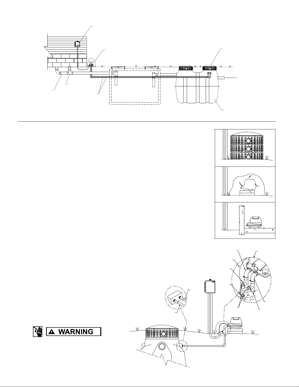
Figure 11, Typical Fusion® Layout
WARNING!
CLEAN - OUT
SEWER LINE
FUSION CONTROL PANEL
AIR LINE
BLOWER
RISER AND LID
TO DRAIN FIELD
OPTIONAL SEPTIC TANK INSTALLATION
MAY BE REQUIRED BY LOCAL
OR STATE REGULATIONS
BLOWER INSTALLATION AND PLACEMENT
1. The blower must be connected to a grounded, metallic, permanent wiring system, or
an equipment-grounding terminal or lead on the product.
2. Place the blower where it is easily accessible for maintenance and inspection.
3. Install the blower in an area where it will be protected from damage and inundation.
Also make certain the location has good ventilation.
4. Install the blower on a foundation that is level and solid.
5. Excavate trenches for two air lines from blower to the unit.
6. Install two separate 1/2" (13 mm) air lines from the blower to the unit. Length of piping
must be less than 17' (5 m). If distances from 17' (5 m) to 33' (10 m) are required,
use 3/4" (19 mm) diameter piping (Figure 12). If longer air lines are needed, consult
the factory.
7. The blower is provided with two discharge ports. The blower label is color-coded with the
aeration outlet port being BLUE and the backwash outlet port being RED (Figure 12).
®
8. The air port inlets on the Fusion
for backwash (Figure12).
9. Attach the barbed end of each PVC tee (included in the blower box) to the blower
using the rubber elbows (Figure 12).
10. Attach the small diameter black air tubing (included in the blower box) to barbed tting
on PVC tee. Black air tubing and blower power cord should be routed to the alarm
panel through conduit. Attach the two black air tubing lines to the two air pressure
sensor barbed ttings in the alarm panel (Figure 12).
11. Connect the remaining end of each PVC tee to the airlines installed in Step 6.
are also color-coded, BLUE for aeration and RED
FUSION
RISER CONFIGURATION
DECORATIVE ROCK CONFIGURATION
INTERIOR CONFIGURATION
RED AIR
LINE
POWER
CORD
AIR LINE
TO PANEL
ADAPTER
sk2650
BLOWER
TO PREVENT ELECTRICAL SHOCK FROM
BACK-SIPHONING, LOCATE THE PUMP
ABOVE THE WATER LEVEL.
Figure 12
BLUE AIR
LINE
© Copyright 2012. All rights reserved.
8
RED AIR
LINE
!
CONDUIT TO
PANEL
TO PANEL
AIR LINE
BLUE AIR
LINE
sk2639
RUBBER
ELBOWS
Page 9
P R E L I M I N A RY
PIPING INSTALLATION
1. Connect house sewer pipe or septic tank outlet, if
required, to the unit inlet. Make certain only household
waste enters the unit (no foundation drains, gutter
drains, oor drains, etc.).
2. Connect the outlet pipe to the outlet of the unit.
HIGH WATER ALARM FLOAT INSTALLATION
The Fusion® alarm panel assembly includes a high water
alarm oat switch that is used to monitor the liquid level in
the Fusion
the gray, vertical air lines in the aeration chamber. With
a 3" (76 mm) tether length, the cord should pass through
the opening in the partition wall between the aeration and
anaerobic chamber and allow the oat to hang in the outlet
bafe of the anaerobic chamber.
1. The oat switch should be tethered to one of the gray,
2. Place the cord into the clamp and secure to gray aeration
3. Position the oat with a 3" (76 mm) tether.
4. Tighten the clamp with a screwdriver. Be careful not
5. Make sure the oat cord is not allowed to touch the
6. The oat switch cord should be installed in an electrical
7. A ½" (13 mm) bulkhead tting (supplied by others)
8. Please be certain that the bulkhead tting for the
9. Electrical conduit from the Fusion
10. The control switch can be wired directly into the alarm
®
unit. The switch should be tethered to one of
vertical pipes in the aeration chamber. When the oat
is in the horizontal position, the cord should be at
least 1" (25 mm) below the top of the partition wall
opening in the anaerobic chamber bafe.
pipe. NOTE: Do not install the cord under the clamp.
to overtighten as this may cause damage to the plastic
clamp.
excess clamp band during operation as this may
cause damage to the cord.
®
conduit connecting the alarm panel to the Fusion
The electrical conduit must be rated for burial, and should
be properly sealed to prevent gases from entering the
alarm panel.
should be used to connect the electrical conduit to the
®
Fusion
the Fusion
ttings to facilitate this connection.
electrical conduit forms a watertight connection with the
FRP wall of the Fusion
panel can be buried in the same trench as the air lines.
panel. See Figure 7.
unit. A hole must be drilled through the wall of
®
unit between the red and blue bulkhead
®
unit.
®
unit to the alarm
unit.
ELECTRICAL CONNECTIONS
1.
the National Electrical Code and/or your local/state
electrical codes.
2. The blower should be directly wired into the alarm panel.
The alarm panel must be located in a dry location that
is accessible for maintenance. Please see Figure 7 and the
wiring diagram and instructions enclosed with the alarm panel.
3. Make certain the timer within the control panel is set to
the proper time. The timer unit display should be set to
10 hrs. and the timer dial needle set to 3.6 for 36 hours.
This will activate an alarm if the blower doesn't go into
backwash cycle within a 36-hour time frame.
All electrical installations must follow
START UP
is furnished with the information package in the blower box.
Please use this as a guide and ll out all sections and return
to your distributor.
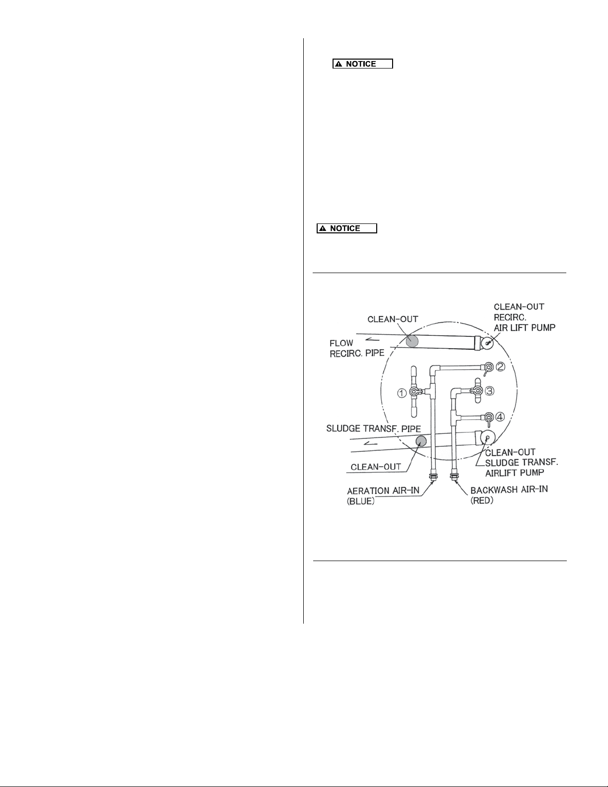
Figure 13- Aeration Flow Adjustment
Valve Legend:
1. Aeration Blue 3. Backwash Red
2. Recirculation Gray 4. Sludge transfer Gray
There are two aeration systems provided within the aeration
chamber: normal aeration and backwash. Valves (1 and 3) are
set at 50%. Observe the air ow on each side of the unit to verify
equal ow. If there is an obvious discrepancy in air ow between
the two sides, adjust the valves (1 and 3) so that the ow is equal.
An installation and start-up check list (CL0057)
© Copyright 2012. All rights reserved.
9
Page 10
RECIRCULATION FLOW ADJUSTMENT
BACKWASH FLOW ADJUSTMENT
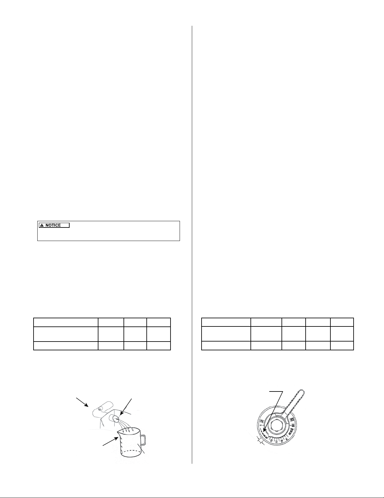
The recirculation ow is designed to be 1.2-1.8 times that
of the average design inow. Table 4 indicates starting
ow rates for each unit. However, ne adjustments may be
necessary to ensure optimum performance.
Setting the ow rate:
• Adjust the ow using rates in Table 4.
• The ow rate is adjusted by rotating the gray recirculation
valve (2) and observing the ow at the pipe end.
• There are prescribed lines at the outlet of the recirculation
pipe to aid in approximating the correct ow.
Measuring the ow rate:
• The actual ow rates must be measured to verify ow
after adjustment of the valve and observation at the
pipe end.
• Measure the time in seconds required to ll a 1L
container.
• Compare the time to value ranges in Table 4.
• If necessary, adjust the valve again and collect another
sample to verify the correct ow rates.
It is important not to set the flow rate too high
because it can cause excessive agitation within the first chamber
(Sedimentation Chamber). This could result in poor performance.
In order to prevent plugging of the media in the Aeration
Chamber, the backwash cycle activates at a preset
schedule. If there is no backwash cycle or too short
of a backwash cycle, the unit’s performance will be
adversely affected. Likewise, if the backwash cycle is
too long, performance will be compromised.
The backwash cycle begins at 2:00 AM and lasts for ve
minutes. One hour later, another ve minute backwash
cycle occurs. Even with these default settings, the waste
water inow could be too low or too high to optimize
the performance and therefore, must be checked during
each inspection. The backwash initiation time can be
set for any time during a
24-hour period to accomodate unusual water use
patterns. The goal is to set the time when there is no
ow into the unit.
The backwash cycle and sludge transfer from the
Aeration Chamber takes place at the same time.
Verify that the air ow is uniform across the Aeration
Chamber between the two sides during a backwash
cycle. If not, adjust the red backwash valve (3)
accordingly.
Setting the ow rate:
• Switch to a manual backwash cycle by pressing
the pink "Manual Backwash" button on the blower
control pad.
• Set the backwash ow rate by adjusting the gray
sludge transfer valve (4). Use Table 5 to determine
the setting for each Fusion® model.
Measuring the ow rate:
• Measure the actual backwash ow rate at the
outlet of the sludge return pipe in the rst chamber
the same way the recirculation ow rate is measured.
• Adjust the gray sludge transfer valve (4) if
necessary to obtain the proper ow.
• Return the blower to normal aeration mode by
pressing the pink button on the blower's control pad.
Table 4 - Recirculation Flow Rates
Model ZF450 ZF600 ZF800
Recirculating ow rate
(sec/liter)
Suggested Valve Opening 35-40% 30-35% 30-35%
Figure 14 - Flow
Measurement
RECIRCULATION OR
BACKWASH PIPE
CONTAINER
29-45 21-32 14-22
MARKER
© Copyright 2012. All rights reserved.
10
Table 5 - Backwash Flow Rate Setting
Model Frequency ZF450 ZF600 ZF800
Backwash ow rate
(sec/liter)
Valve open (%) Twice/day 50-55 40-45 40-45
Figure 15 - Flow
Controlling Valve
Twice/day 7-10 5-7 4-6
DOTTED
SCALE
SUGGESTED
RANGE
VALVES
Page 11
P R E L I M I N A RY
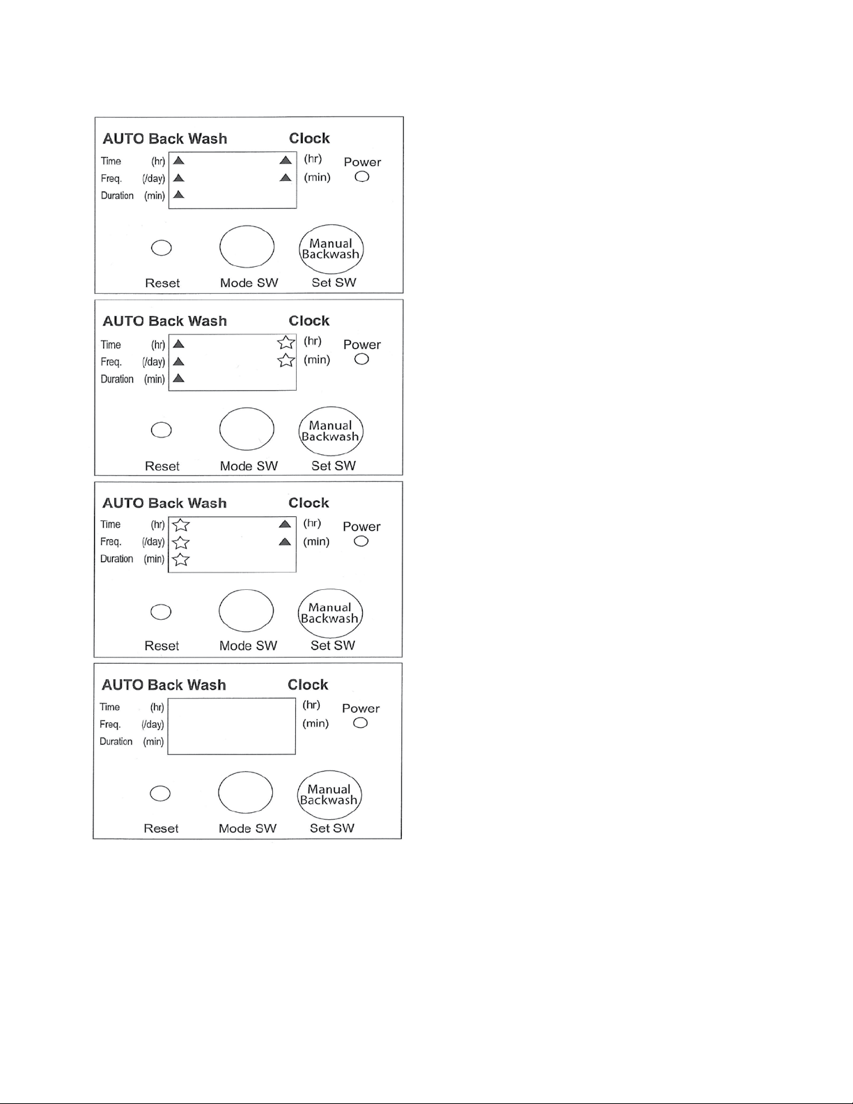
Figure 16
BLOWER TIMER SETTING
Reset (factory default settings):
Press Reset.
Clock is set to 0:00 (midnight).
Backwash Time is set to 2:00 AM.
Backwash Frequency is set to 2 per day. Backwash
Duration is set to 5 mins.
To Adjust Clock & Backwash Settings:
1. Press Mode SW. Note the blinking arrow indicating
"hr" under "Clock" at the right of the screen.
2. Press Set SW to select the current hour of the day.
3. Press Mode SW. Note the blinking arrow indicating
"min" under "Clock" at the right of the screen.
4. Press Set SW to select the current minute of the hour.
5. Press Mode SW. Note the blinking arrow indicating
"Time hr" under "AUTO Back Wash" at the left of the
screen.
6. Press Set SW to select the hour that the system will
begin to back wash. (A setting of 2 is standard)
7. Press Mode SW. Note the blinking arrow indicating
"Freq./Day" under "AUTO Back Wash" at the left of
the screen.
8. Press Set SW to select either 1 or 2 back wash cycles
that the system will perform per day. A setting of 2 is
standard.
9. Press Mode SW. Note the blinking arrow indicating
"Duration min" under "AUTO Back Wash" at the left of
the screen.
10. Press Set SW to select either 5 or 10 minute duration
for back wash cycle. A 5-minute cycle is standard.
NOTE: A 24-hour clock is used in place of AM/PM
designations.
© Copyright 2012. All rights reserved.
11
Page 12

FUSION® OPERATION AND MAINTENANCE
The following steps are to be completed during each 6- month
inspection. All information collected during the inspection is to be
recorded on the Maintenance and Service Report (CL0059). Begin
the inspection by recording the date, arrival time, weather conditions,
purpose of the visit, water use, model number, serial number, the
presence or absence of a septic tank, and the system owner and
service provider information in the space provided on the report.
GENERAL OBSERVATIONS
1. Are any odors present? There should be no odor
with the lids closed, if properly sealed. With lids
removed, a septic or sewer-like odor is indicative
of poor treatment and is common immediately after
startup due to hydrogen sulde and other gases. A
well-operating system will have a musty, earthy smell
similar to wet peat moss.
2. Are any insects present? Typically, no insects
are present in the cold weather months. In warmer
months, sewage ies can be found inside risers, on
the underside of lids, and larvae can be found in the
scum layer of the sedimentation chamber.
3. Is there evidence of high water? Typically indicated
by a water level above the black wall markings and
above the “0” graduation on the partition wall stickers.
May also be indicated by debris on partition walls.
4. Is there excess foam formation? Foam may be
present during an inspection. Brown foam indicates
bacterial buildup following startup. White foam is due
to detergent use. Neither is a problem if occurring
intermittently. Detergent-based foam will often be
accompanied by low transparency readings.
5. Is there residue build-up on piping? Typically
indicated by gray or black residue (dried foam) on
aeration chamber piping.
6. Is there even and vigorous bubbling? Bubbles
surfacing in the aeration chamber should be even
across the entire chamber. If uneven, cleaning steps
should resolve this issue.
REQUIRED WATER QUALITY ANALYSES
PART A: Clean Water Storage Chamber – Collect samples
from the clean water storage chamber to be used for the
following analyses
1. pH – Measures the hydrogen ion-concentration and is
determined with the use of the pH test strips included
in the Fusion
water sample for 1 second, remove, and read by comparing
to the color chart provided on the container. A pH = 7.0
is neutral. The range suitable for biological activity is 6.5
to 7.5. Recurring results outside this range should be
investigated – check the water source for the home or
business, chemical use, etc.
2. NO
-
N – Determined with the use of the nitrite test strips
2
included in the Fusion
into the water sample for 1 second, remove, allow to
react for 30 seconds and read by comparing to the color
chart provided on the container. Nitrite-nitrogen is an
intermediate step in the oxidation of ammonia to nitrate
and the reduction of nitrate. 0 to 3 mg/L is common and
1mg/L is average. The presence of nitrite is indicative of
biological activity. The absence of nitrite could be due
to a young system or a recirculation rate that is too high.
To correct low nitrite readings in established systems,
decrease the recirculation rate.
®
Maintenance Kit. Dip a test strip into the
®
Maintenance Kit. Dip a test strip
© Copyright 2012. All rights reserved.
3. Transparency – Measures the ability of the water to
transmit light. Using the ladle, ll the transparency tube
with a water sample collected from the clean water storage
chamber. Looking down through the water column,
slowly drain the transparency tube using the valve on the
exible hose until you can rst distinguish between the
black and white colors on the secchi disk in the bottom
of the tube. When the secchi disk is visible, close the
valve and read the transparency (in centimeters) on the
side. Dirty water samples transmit less light and result
in a lower transparency. A transparency reading > 20
cm is preferred and 34 cm is average. Low transparency
may be due to a lack of biological activity as in a young
system, a recirculation rate that is too high, or a system
inuent high in detergent concentration. To correct low
transparency readings not caused by detergent, decrease
the recirculation rate. Detergent based problems may
require consultation with owner.
4. Scum – Very small amounts of scum may accumulate
in the corners on the outlet end of the system. This is
normal. Scum, should not be present elsewhere in the
clean water storage chamber unless the recirculation rate
is too high or daily ow exceeds the design capacity. If
present, use ladle to transfer to sedimentation chamber.
5. Sludge – Test the sludge depth using the sampling device
included in the maintenance kit. The bottom section of
the sampler includes a check valve, which opens as the
unit is lowered into the liquid. When the sampler has
reached the bottom of the chamber and the liquid level
equilibrated at surface level, lift the sampler and this
action will set the check valve and retain the sample in
the tubing. Withdraw the sampler and note the depth of
settled solids within the sample. To release the material
in the unit, touch the stem extending from the bottom
section against a hard surface such as the partition wall
in the sedimentation chamber. This opens the check
valve to drain the sample. A range of 0” to 4” is preferred.
Typically solids are brown and well occed. More than 4”
(0-102 mm) is typically due to high recirculation rates and
sludge will appear black in color. To correct sludge depths
greater than 4” (0-102 mm), decrease the recirculation
rate and increase the backwash rate.
Sludge Descriptions:
Black – septic or sewer-like odor due to hydrogen sulde
and other gases
Brown – undigested sludge is light brown, becomes
darker with digestion, lightly settled
Clear – may see a clear water layer beneath solids if gas
carries solids upwards
Flocced - settled with texture similar to a tuft of wool
Grainy - gritty or sandy texture
Gray - partially digested sludge
Milky – light in color, cloudy, not transparent
Muddy – typically well settled, often present just after
startup, may be due to inltration
Mustard - an off-color, remnants of digestion are often
yellowish in color
White - sometimes present after new construction often
due
to drywall mud
PART B: Anaerobic Chamber - collect samples from the
outlet bafe of the anaerobic chamber to be used for the
following analyses:
12
Page 13
P R E L I M I N A RY
FUSION® OPERATION AND MAINTENANCE, continued
1. Transparency – A transparency reading more than 20
cm is preferred.
2. Scum – Should not be present unless recirculation
and/or backwash rate is too high or daily ow exceeds
design capacity. To correct, reduce the recirculation and
or backwash rate.
3. Sludge – A range of 0” to 15” (0-38 cm) is preferred.
Typically brown and settled, becomes gray to black
as depth and digestion increases. More than 15” (38
cm) may require a reduction in recirculation rate. A
sludge accumulation of greater than 24” (61 cm) in the
sedimentation and 15” (38 cm) in the anaerobic chamber
requires pumping.
PART C: Sedimentation Chamber – collect samples
from the outlet bafe of the sedimentation chamber for the
following analyses:
1. Scum – 0” to 12” (0-30.5 cm) is common, so long as it
is not rising above the partition wall. If so, punch down
using ladle.
2. Sludge – A range of 0” to 24” (0-61 cm) is common.
Typically brown and settled, becomes gray or black as
depth and digestion increases. A sludge accumulation
of > 24” (61 cm) in the sedimentation chamber and 15”
(38 cm) in the anaerobic chamber requires pumping.
OPTIONAL WATER QUALITY ANALYSES
PART D: Clean Water Storage Chamber – samples should
be collected as previously described.
1. NO
2. NH
strips included in the Fusion Maintenance Kit. Dip a test
strip into the water sample and move up and down for 30
seconds, remove, allow excess water to drain, allow to react
for 30 seconds, and read by comparing to the color chart
provided on the container. Ammonia-nitrogen is measured
using low range test strips, 0-6 mg/L. Average is 3.0
mg/L. Low ammonia readings are desirable and require no
changes. To correct high ammonia readings decrease the
recirculation rate.
-
N – Determined with the use of the nitrate test strips
3
included in the Fusion Maintenance Kit. Dip a test strip
into the water sample for 1 second, remove, allow to
react for 60 seconds, and read by comparing to the color
chart provided on the container. Nitrate-nitrogen is the
nal step in the oxidation of ammonia. The test strips
provided range from 0-50 mg/L. Average is 7.0mg/L. No
or low nitrate concentrations are common in systems
where nitrifying microbes are absent. To correct high
nitrate concentrations in established systems increase the
recirculation rate.
-
N – Determined with the use of the ammonia test
3
3. Dissolved oxygen – Follow the instructions included
with the dissolved oxygen meter. D.O. should be measured 25
inches (635 mm) below the water level. Average is 2.0 mg/L.
4. Temperature – Most dissolved oxygen meters include
a built-in thermometer which can be used to measure
temperature. Varies with system location.
PART E: Anaerobic Chamber – samples should be
collected and analyses performed as previously described
1. pH – The range suitable for biological activity is 6.5
to 7.5. Recurring results outside this range should be
investigated – water source for the home or business,
chemical use, etc.
-
2. NO
3. NO
4. NH
N – < 3.0 mg/L is common for this chamber.
2
Adjustments should be based on water quality in the
clean water storage chamber.
-
N – < 2.0 mg/L is common for this chamber.
3
Adjustments should be based on water quality in the
clean water storage chamber.
-
N – Ammonia-nitrogen in this chamber is typically <
3
20.0 mg/L. If this test is desired, it should be conducted
with test strips suitable for the expected concentration.
Adjustments should be based on water quality in the
clean water storage chamber.
5. Dissolved oxygen – Typically < 0.5 mg/L.
6. Temperature – varies with system location.
PART F: Sedimentation Chamber - samples should be
collected and analyses performed as previously described.
1. pH – The range suitable for biological activity is 6.5
to 7.5. Recurring results outside this range should be
investigated – water source for the home or business,
chemical use, etc.
-
2. NO
3. NO
4. NH
N – < 2.0 mg/L is common for this chamber.
2
Adjustments should be based on water quality in the
clean water storage chamber.
-
N – < 2.0 mg/L is common for this chamber.
3
Adjustments should be based on water quality in the
clean water storage chamber.
-
N – Ammonia-nitrogen in this chamber is
3
typically < 30 mg/L. If this test is desired, it should be
conducted with test strips suitable for the expected
concentration. Adjustments should be based on
water quality in the clean water storage chamber.
5. Transparency – Typically < 15 cm. Adjustments should
be based on water quality in the clean water storage
chamber.
6. Dissolved Oxygen – Typically < 0.5 mg/L
7. Temperature – Varies with system location
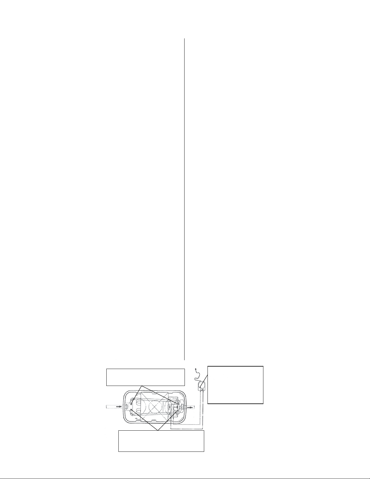
Figure 17 - Inspection details
RECIRCULATION SYSTEM
1. Measure the recirculation flow
2. Cleaning
BACKWASH SYSTEM
1. Measure the current backwash flow
2. Cleaning
3. Alternating backwash time and frequency
© Copyright 2012. All rights reserved.
BLOWER AND
CONTROL PANEL
1. Power failure
2. Blower timer setting
3. Noise and vibration
4. Air filter replacement
5. Diaphragm replacement
13
Page 14
AERATION CHAMBER CLEANING
1. Aeration
The aeration system must be ushed every maintenance
visit. There are two ushing methods: (A) Air ushing
and (B) Water ushing. Air ushing must be done every
maintenance visit. Water ushing may be done if there is
a sign of clogging in the Aeration Chamber (e.g. abnormal
increase in recirculation ow).
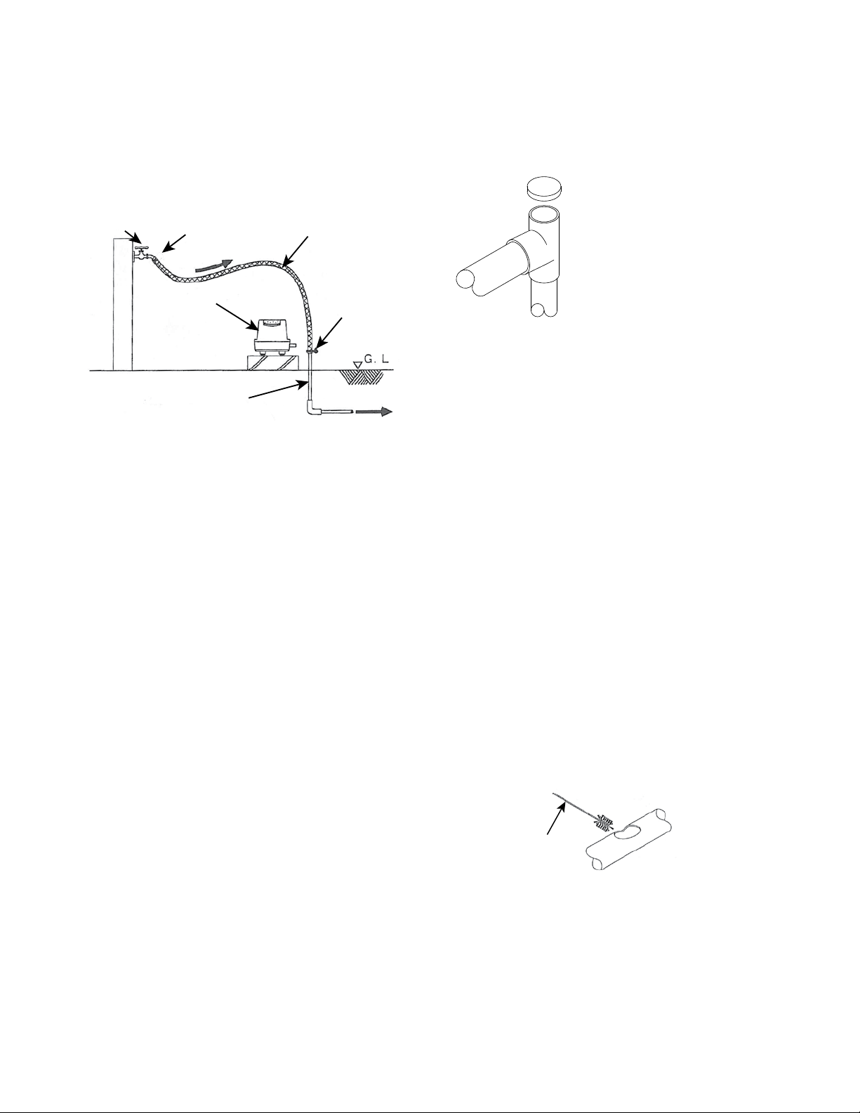
Figure 18
FAUCET
BACKFLOW
PREVENTER
WATER
BLOWER
EXISTING
AIR LINE
HOSE
CLAMP
.
TO TREATMENT UNIT
(A) Air ushing procedure:
• Make sure the blower is in the aeration mode.
• Close gray recirculation valve (2) all the way. (0%)
• Rotate blue aeration valve (1) back and forth from the
0% to the 100% position several times to ush.
• Set valves (1) and (2) back to the appropriate positions.
(See Recirculation Flow Adjustment, pg. 10)
(B) Water ushing procedure: (See Figure 18)
• Make sure the blower is off.
• Close valve (2) all the way.
• Connect a water line to the aeration line as shown in
Fig. 18.
• Gradually open the water faucet and introduce water
into the system.
• Rotate valve (1) back and forth from the 0% to the
100% position several times to ush.
• Turn off the water, remove the water line, and
reconnect the airline to the blower.
• Set valves (1) and (2) back to the appropriate
positions. (See Recirculation Flow Adjustment, pg. 10)
(C) Cleaning the recirculation line:
• Make sure the blower is in the aeration mode. If not,
change the mode by pressing the Manual Backwash
button.
• Open the gray recirculation valve (2) to 100%.
• Flush water through the recirculation line for several
seconds.
• Turn off the recirculation by rotating the gray valve
(2) to 0%.
• Make sure the blower is off. Allow the system to
relax for a few seconds.
• Repeat this cleaning method three times. • A hose or
brush can also be used to clean the recirculation line.
See Figure 20.
• Reset the gray valve (2) to its original position.
2. Backwash
The backwash system must be ushed every maintenance
There are two ushing methods: (A) Air ushing and
© Copyright 2012. All rights reserved.
14
(B) Water ushing. Air ushing must be done every
maintenance visit. Water ushing must be done if there
is a sign of clogging in the Aeration Chamber (e.g.
abnormal increase in recirculation ow).
(A) Air ushing procedure:
Figure 19
• Make sure the blower is in the
backwash mode.
• Close the gray sludge transfer
valve (4) all the way.
• Rotate the red backwash valve
(3) back and forth from the 0%
to the 100% position several
times to ush.
• Set valves (3) and (4) back to
the appropriate positions.
(See Backwash System) (B) Water ushing procedure:
(See Fig. 19)
• Make sure the blower is off.
• Close valve (4) all the way.
• Connect a water line to the backwash airline as shown in
Figure 16.
• Gradually open the water faucet and introduce water into
the system.
• Rotate valve (3) back and forth from the 0% to the 100%
position several times to ush.
• Turn off the water, remove the water line, and reconnect
the airline to the blower.
• Set valves (3) and (4) back to the appropriate positions.
(See Backwash System)
(C) Cleaning the sludge transfer line:
• Make sure that the blower is in the backwash mode. If
not change the mode by pressing Manual Backwash.
• Open the gray sludge transfer valve (4) to 100%.
• Flush water through the sludge transfer line for a few
seconds.
• Repeat this cleaning method three times.
• A hose or brush can also be used to clean the sludge
transfer line. See Figure 20.
• Reset the gray valve (4) to its original position.
• Return the blower to the normal aeration mode. by
pressing Manual Backwash.
Figure 20
BRUSH
3. Foam formation
Make sure there is not an excess amount of foam on the
surface. If excessive foam is present it may indicate high
detergent usage. Meet with owners to inform and educate
them concerning excessive use.
4. Abnormal water level
If the water level exceeds the partition wall, clean the
plastic cage rst with a brush, then check for possible
clogging in the lter media section. Clogs may be cleared
by using a manual backwash tool. The manual backwash
tool may also be used to eliminate a clog in the anaerobic
chamber media as well.
Page 15
P R E L I M I N A RY
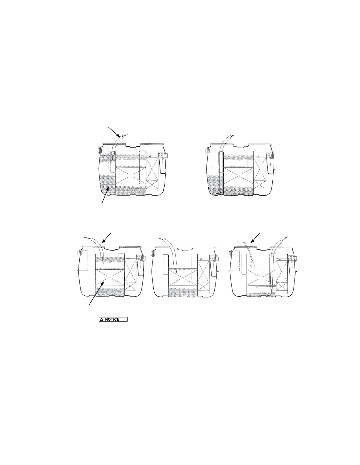
FUSION® PUMPING
Wastewater entering the Fusion® contains organic and inorganic materials. If organic in nature, it is treated and decomposed by
microorganisms during the treatment process. If inorganic in nature, it will be stored within the Fusion
accumulate as scum (oating) or sludge (solids on the bottom) and must be removed periodically to ensure the performance of
the Fusion
scum and sludge have been reached and pumping is required. Follow the procedures in Figures 21 and 22 to remove scum and
sludge from the sedimentation and anaerobic chambers only. When nished, rell both chambers with clean water to prevent the
possibility of otation.
Figure 21 - Sedimentation Chamber Pumping
®
. Please review the Operation and Maintenance sections part B and C to determine when the maximum depths of
Step 1: Remove the scum. Step 2: Remove the sludge
Step 3: Remove the sludge under the media while washing the lter with tap water.
Vacuum
1) 2)
®
. The stored materials
Sedimentation-separation tank
Figure 22 - Anaerobic Chamber Pumping
1)
Step 1: Remove the scum.
Anaerobic lter tank
Vacuum
: Remove the scum rst. If you remove the sludge rst, the
water level will decrease and the anaerobic lter will be blocked by the scum.
2)
ALARM PANEL & BLOWER INSPECTION AND MAINTENANCE
Inspect the alarm panel for signs of water or odors inside.
Toggle the test switch on the side of the box to check that both
the alarm horn and the alarm beacon light are operational.
Inspect the blower for proper operation. If the blower is not
functioning, refer to the troubleshooting section near the end of
this guide.
1. Listen for loud rattling sounds. The blower should hum
softly. If a rattle is heard, ensure that all four legs
securely contact the ground or base medium.
2. Inspect the lter once the power has been disconnected
by removing the lter retention screw. Then, remove
the cover by snapping the lter cover off the top of the
blower. Clean the lter by knocking the dust out or by
rinsing with water to remove accumulated particles. Be
sure the lter is dry before reinstalling.
© Copyright 2012. All rights reserved.
3)
Step 2: Remove the sludge
on the lter media.
3. Ensure the correct time is shown on the blower's display
screen, keeping in mind that the display shows a
24-hour clock (not AM/PM).
4. Press the Manual Backwash button and ensure the unit
switches into backwash mode by observing the change
in water ow in the Fusion
return line to the sludge transfer line. Be sure to switch
the system back to recirculation by pressing the Manual
Backwash button again.
15
Tap water
®
tank from the recirculation
Page 16

TROUBLESHOOTING
1. Odor
Offensive odors are often the result of insufcient or
inappropriate bacterial growth. Causes may include
a young or unestablished system, insufcient air
introduction, or the addition of detrimental chemicals
or poisons into the system. Ensure the blower and air
delivery systems are functioning. Check with the owner
regarding chemical use and disinfection habits. Check all
risers and lids to ensure an airtight seal.
2. Foam Formation
Foam formation is observed in the following situations:
1. In the early stage of operation when the
aerobic bacteria colony is establishing itself.
2. When an excess amount of air is supplied for aeration.
3. When the difference between ambient
temperature and water temperature is great.
4. When an excessive amount of detergent is
introduced.
In most cases, foam will disappear with proper operation.
When excessive amounts of detergent have been
introduced to the system, remind the owner to use
appropriate amounts of detergent.
3. Cloudy Treated Water
• Check the amount of scum and sludge:
If too much scum or sludge is observed, transfer
them to the rst chamber and adjust recirculation ow
rate as well as backwash time, frequency and duration.
(See backwash ow adjustment)
• Check the aeration situation:
If uneven bubble generation is observed, adjust
valve (1). If aeration is weak, ush the aeration
pipe with air or water.
• Check the recirculation ow rate:
If the recirculation ow rate has increased
after the last inspection, the aeration pipe may
be clogged. Flush the aeration pipe with air or
water. If the recirculation ow rate has decreased after
the last inspection, the airlift pump or recirculation
pipe may be clogged. Clean them with a brush and
running water.
• Check the color of the returning sludge from the
backwash pipe:
If the color is abnormally dark, decrease the
recirculation ow rate accordingly. If the TSS of
the water from Anaerobic to Aeration Chamber is
high, check the sludge accumulation. If the sludge
accumulation reaches the upper limit, pump out the
sludge. If not, backwashing the Anaerobic Chamber by
using a manual backwash tool (Figure 18) may assist.
4. Blower
Blower motor does not run, with power connected:
• Check the electric supply to the panel, ensuring 120
volt service.
• Check that all breakers and fuses in the panels are
on and intact.
• Check the blower's Auto Stop Mechanism
(see Figure 24).
Little or No Aeration / Backwash Air:
• Check the blower motor is running.
• Check the air line piping connectons at the blower.
• Check the air lter and clean or replace if necessary.
• Check the diaphragms and replace if necessary.
• Check the air piping for leaks, clogs, or dislocations and
correct accordingly.
• Verify check valves (if installed) in supply lines are
installed correctly.
Blower - manual backwash does not work:
• Push the manual backwash button several times,
listening closely for a light click within the unit.
• If the unit clicks, but the air does not switch from
aeration to back wash, consult the factory.
© Copyright 2012. All rights reserved.
16
Page 17
P R E L I M I N A RY
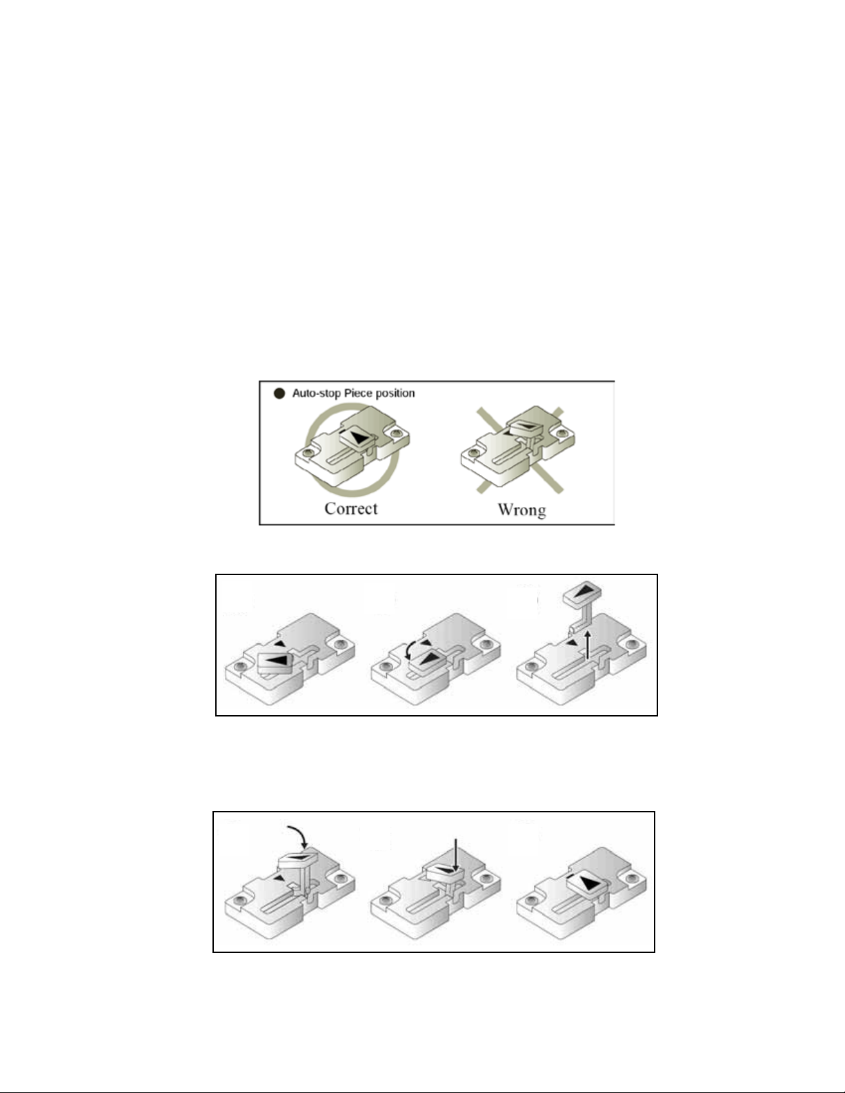
Auto Stop Mechanism
The Fusion® blower is equipped with an Auto Stop Mechanism designed to protect the motor in the event of a
diaphragm rupture. If tripped, the screen display on the blower will remain functional, but the blower motor will not
operate. Follow the directions below (Figure 24) to check and reset the Auto Stop Mechanism:
1. Turn off the blower's breaker in the control panel. Ensure that the blower motor has stopped and the unit does not
have power.
2. Remove the four screws securing the blower cover to the blower base and remove the cover.
3. Remove the insulation felt from around the motor.
4. Observe the position of the auto stop break bar. If the arrow on the auto stop break bar does not line up with the
arrow on the auto stop base plate, then a trip has occured. IMPORTANT: IF THE AUTO STOP HAS TRIPPED, DO
NOT REINSTALL THE AUTO STOP BREAK BAR UNTIL THE DIAPHRAGMS HAVE BEEN INSPECTED OR
REPLACED!
5. To remove the auto stop break bar, rotate the piece 90°, couter-clockwise and lift out.
6. To reinstall the auto stop break bar, line up the arrows on both the bar and the base, insert the tip of the bar through
the plate, and push the bar straight down to snap it in place.
Figure 23
Rotate the auto-stop
bar to one side.
Turn until the mark is
inline with the opening
in the plastic handle.
Remove the auto-stop bar.
Align the marks on each
piece and slide the piece
into the holder.
© Copyright 2012. All rights reserved.
Push in until it clicks. Ready for use.
17
Page 18
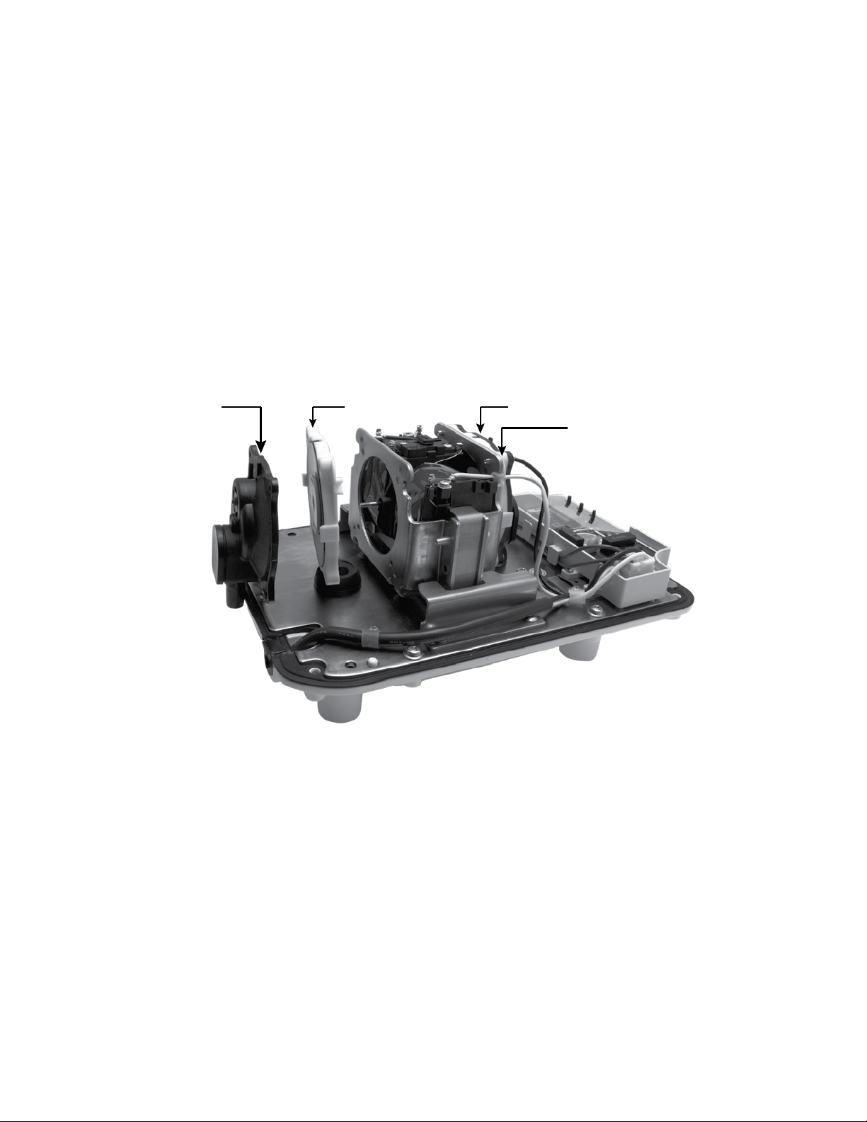
DIAPHRAGM REPLACEMENT
1. Disconnect power to the blower and wait 5 minutes before continuing with service on the unit.
2. Remove the top to the blower (4 Allen head or Phillips head screws attach the top to the base).
3. Remove one of the diaphragm covers (4 Phillips head screws attach the cover to the motor). The cover should easily pull out of
the base.
4. Remove the lock nut holding the diaphragm on (7/32” socket).
5. Replace diaphragm with new diaphragm. The diaphragm can only go on one way. The smaller screw hole spacing must go to the top
of the unit. Any other way and the screw holes will not line up.
6. Replace lock nut.
7. Replace diaphragm cover ensuring that the cover is seated back in the grommet on the base plate, and the four screw holes line up.
8. Repeat procedure for the other diaphragm.
9. Replace the top to the blower and tighten the 4 screws removed earlier.
10. Reconnect power to the unit.
Figure 24
Diaphram
Cover
(removed)
Diaphram
(removed)
Diaphram
Cover
Diaphram
© Copyright 2012. All rights reserved.
18
Page 19

P R E L I M I N A RY
NOTES
© Copyright 2012. All rights reserved.
19
Page 20

Your Peace of Mind is Our Top Priority
®
3649 Cane Run Rd. • Louisville, KY 40211-1961 • 877-244-9340 • FAX: 877-414-4316
www.clarusenvironmental.com
 Loading...