

Clarus Environmental 2800, 3200, 3600, 4000 User Manual

®
®
3649 Cane Run Road . Louisville, KY 40211-1961
877-244-9340 . Fax: 877-414-4316
www.clarusenvironmental.com
Fusion® Series Treatment Systems
OWNER'S MANUAL
Large Commercial Models ZFL-2800 – ZFL- 4000
Thank you for choosing a Fusion® Series Treatment System. Highquality workmanship and easy maintenance have been incorporated
into the Fusion® system. The system will provide years of troublefree service when maintained according to the manufacturer’s
recommendations. Please read this manual in its entirety before using
the Fusion® and follow all instructions to ensure proper operation.
Keep this manual for future reference along with other important
onsite documents. Should further assistance be necessary, please
contact Clarus Environmental at 1-800-928-7867.
Warning Labels
You will nd warning labels on the Fusion®, riser lids, blower, and the
alarm control panel. It is very important to follow the information on
these labels to ensure your safety. Please do not remove these labels.
SEE LIST AT RIGHT
FOR WARNINGS
SECTION: C3.10.142
CL0140
0313
Supersedes
New
1. DO NOT attempt to service the Fusion
authorized maintenance provider for all service related issues.
2. There are buried electrical cables and piping near and around
the Fusion®. Please consult with your authorized maintenance
provider to locate these utilities before excavation.
3. DO NOT bury or cover the Fusion® lids with soil or other debris.
This is necessary to allow access for operation and maintenance
of the unit.
4. The Fusion® blower must be unobstructed and vented for
proper operation. Care must be taken that no grass clippings or
other materials accumulate on or around the blower and block
ventilation.
5. DO NOT place heavy objects over the Fusion® or drive heavy
equipment over the Fusion®, as damage may occur. Damage of
this kind is not covered by the warranty.
6. DO NOT plant trees within 15 feet (4.6 m) of the Fusion
Treatment System.
®
unit yourself. Contact your
®
Series
TABLE OF CONTENTS
Limited Warranty ......................................1
Process Description.................................... 3
System Components and Care ...........................4
Installation and Start Up ................................6
Blower Installation And Placement........................7
Operation and Maintenance ............................ 11
Aeration Chamber Cleaning ............................13
Troubleshooting ...................................... 14
Blower Inspection and Maintenence .....................15
LIMITED WARRANTY
Manufacturer warrants, to the purchaser and subsequent owner during
the warranty period, every new product to be free from defects in material
and workmanship under normal use and service, when properly used and
maintained, for a period of two years from date of purchase by the end
user. No allowance will be made for shipping charges, damages, labor or
other charges that may occur due to product failure, repair or replacement.
This warranty does not apply to and there shall be no warranty for any
material or product that has been disassembled without prior approval of
Manufacturer, subjected to misuse, misapplication, neglect, alteration,
accident or act of nature; that has not been installed, operated or maintained
in accordance with Manufacturer's installation instructions; that has been
exposed to outside substances including but not limited to the following:
sand, gravel, cement, mud, tar, hydrocarbons, hydrocarbon derivatives (oil,
gasoline, solvents, etc.), or other abrasive or corrosive substances, wash
towels or feminine sanitary products, etc. in all pumping applications. The
warranty set out in the paragraph above is in lieu of all other warranties
expressed or implied; and we do not authorize any representative or other
person to assume for us any other liability in connection with our products.
The Fusion® Series Treatment Systems represent a collaboration with Fuji Clean Co., Ltd.
© Copyright 2013. All rights reserved.
Fusion® Model: ZFL-2800 ZFL-3200 ZFL-3600 ZFL- 4000
Serial No. ____________________________________
Installing Contractor ____________________________________
Phone Number ____________________________________
Installation Date ____________________________________
Maintenance Provider’s Name _____________________________
Phone Number ____________________________________
Contact Manufacturer at, 3649 Cane Run Road, Louisville, Kentucky 40211,
Attention: Customer Support Department to obtain any needed repair or
replacement of part(s) or additional information pertaining to our warranty.
MANUFACTURER EXPRESSLY DISCLAIMS LIABILITY FOR
SPECIAL, CONSEQUENTIAL OR INCIDENTAL DAMAGES OR
BREACH OF EXPRESSED OR IMPLIED WARRANTY; AND
ANY IMPLIED WARRANTY OF FITNESS FOR A PARTICULAR
PURPOSE AND OF MERCHANTABILITY SHALL BE LIMITED TO
THE DURATION OF THE EXPRESSED WARRANTY.
Some states do not allow limitations on the duration of an implied warranty,
so the above limitation may not apply to you. Some states do not allow
the exclusion or limitation of incidental or consequential damages, so the
above limitation or exclusion may not apply to you.
This warranty gives you specic legal rights and you may also have other
rights which vary from state to state.
HOW A FUSION® SERIES TREATMENT SYSTEM WORKS
The Fusion® is simple in design, yet advanced in its wastewater
treatment ability. The design has been rened over many years of
intense research and development in an effort to perfect this superior
treatment system. Fusion
®
systems are 90% - 95% efcient at treating
wastewater. This is nearly twice as effective as a traditional septic tank,
which is approximately 50% efcient. This high degree of treatment
helps to protect both your personal property and the environment.
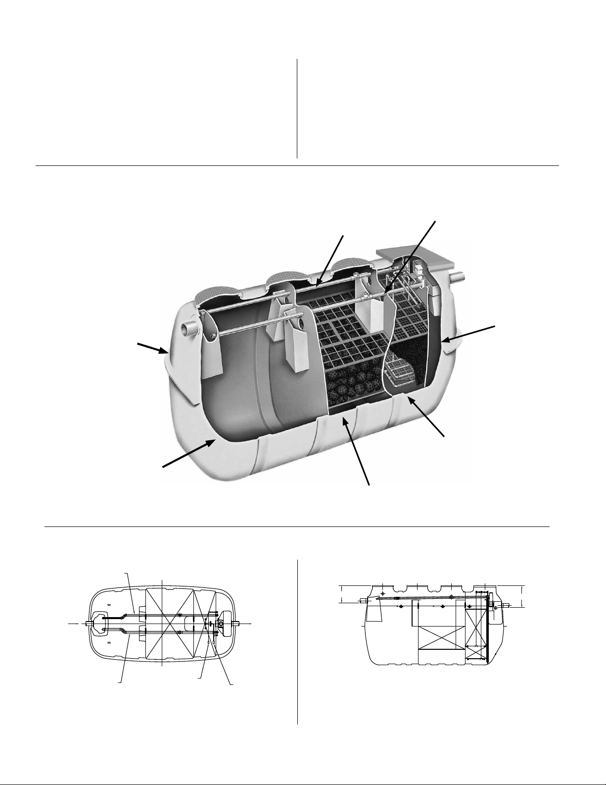
Figure 1 - The following diagram will help you to better understand the process:
Tank -
Fiberglass
The Fusion® utilizes a combination of anaerobic (without oxygen) and
aerobic (with oxygen) biological processes to treat wastewater. As
wastewater enters the Fusion®, it is broken down and becomes food
for biological organisms operating within the unit. The rst chamber
serves to separate some grease and large solids from the liquid. In
the second chamber, plastic media with large surface areas are used
to increase contact between water and benecial bacteria to optimize
treatment. A small linear air blower is used to move air (oxygen) into
the third chamber for the aerobic process. The nal efuent leaving the
system will have been treated to secondary quality efuent.
Sludge Return Line
Recirculation Line
Storage
Chamber
Sedimentation
Chamber -
Separates bulk solid
and grease waste
Figure 2 - Schematic diagram of the Fusion® Treatment System
2" RECIRCULATION
RETURN LINE
INLET
2" BACKWASH
RETURN LINE
3/4" AIRLINE ADAPTER
RECIRCULATION
1" AIRLINE ADAPTER
BACKWASH
TOP VIEW SIDE VIEW
OUTLET
Anaerobic Chamber -
Organisms adhere to xed lm
media and digest waste
21
*
Aeration Chamber
Floating/Circulating
Filter Media -
“Fluidized Bed”
Invigorates aerobic bacteria
W .LW .L W .L
Risers not installed
*
W .L
28
*
© Copyright 2013. All rights reserved.
2
PROCESS DESCRIPTION
1. Sedimentation Chamber
This chamber is designed to physically separate solids from the
incoming water. Scum is the oating material and sludge is the
material that has settled at the bottom.
2. Anaerobic Chamber
This chamber contains a spherical skeleton-type of lter media,
4.3 inch diameter (109 mm). Through bacterial growth processes
on the surface of the lter media, biological anaerobic treatment
thrives while suspended solids are captured. Furthermore,
the microorganisms in this chamber convert nitrates in the
recirculated water returning from the aerobic chamber to
gaseous nitrogen. The gaseous nitrogen then escapes to the
atmosphere.
3. Aeration Chamber
The aeration chamber consists of an aerated upper section and
a lter media lower section. The chamber is lled with hollow,
Figure 3 - Treatment Flow of the Fusion® System.
cylindrical lter media 0.6 inch diameter (15 mm) and 0.55 inches
long (14 mm). Biological treatment takes place on the lter
media surface. Aeration is continuous. Residual suspended
solids are captured by the lter media circulating in this section.
During normal operation, a recirculation line transfers water back
to the sedimentation chamber by way of an air lift pump.
The lter media in the aeration chamber are backwashed
regularly (twice a day, 5 or 10 minute cycle) by the backwash
system located at the bottom of the chamber. The accumulated
sludge is transferred by an air lift pump back into the
sedimentation chamber for further digestion.
4. Storage Chamber
This chamber is designed to temporarily store treated water
exiting the aeration chamber. This treated water is ready for
discharge.
Inflow
Back-Wash
1
2
Sedimentation Chamber
Anaerobic Chamber
Recirculation
3
4
Aeration Chamber
Storage Chamber
Effluent
© Copyright 2013. All rights reserved.
3

SYSTEM COMPONENTS
The complete wastewater treatment system will typically consist of the Fusion® treatment components and a soil absorption eld for nal
disposal of the liquid efuent. Some states or counties may require the addition of a septic tank before the Fusion® to increase the sedimentation
chamber capacity and retain more solids. Please see Figure 9 for a typical Fusion® system. Variations to the typical system will be made to suit
your particular site and system design needs. Please contact your authorized Fusion® installer or maintenance provider for further information
about your system design.
1
2 3 4 5 6 7 8
ALARM PANEL
The Fusion
audible buzzer and red beacon light on top of the panel if there is a drop
in air pressure, if a high water alarm condition occurs, or if the blower
®
alarm panel (see Figure 4) is designed to activate an
120 VAC
INCOMING
POWER
GND
TB2
L1
N
DISNF
ALARM
GND LUG
does not cycle between recirculation and backwash modes within the
preset time. (Note: Alarm panel can only function as long as there is
electrical power supplied to the panel)
HIGH WATER
ALARM
You may from time to time check the proper operation of the alarm
panel by toggling the black switch on the side of the panel to “test”. The
buzzer will sound and the red beacon will light as long as you hold the
switch in the test position. Release the switch for normal operation.
Figure 4
BLOWER
*FOR ILLUSTRATION PURPOSES ONLY*
REFER TO SCHEMATIC LOCATED IN
PANEL FOR INSTALLATION
SK2933
SYSTEM CARE
The Fusion
blower area is recommended to ensure no debris obstructs the ventilation or intake areas of the blower. Also, periodically test the control panel
as outlined under the alarm panel section. The owner should closely monitor the types and amounts of substances and products used. Water use
should also be closely monitored to ensure proper operation of the Fusion® system.
Periodically, more extensive maintenance must be performed. Your authorized Fusion® maintenance provider will oversee this service. The name
of the maintenance provider can be recorded on the front of this document and should also be located on the alarm panel. For more information
see the Operation and Maintenance section of the manual.
The owner should only perform minimal routine maintenance on the Fusion® such as clearing debris from around blower housing (leaves, snow,
and grass clippings). The Fusion® should also be protected from excessive weight such as vehicular trafc. Trees and bushes should not be
planted in close proximity to the Fusion®. The Fusion® should be accessible to maintenance personnel and the riser lids must never be buried.
®
system is designed to continuously operate automatically with little direct maintenance from the owner. Periodically, a check of the
HIGH USE WATER DEVICES
The draining of hot tubs and swimming pools into your Fusion® system
could cause hydraulic overloading and may reduce the treatment
efciency. Please drain these devices to another location. Contact
your local regulatory authorities or authorized Fusion® maintenance
provider for more information. The use of large capacity single ll and
drain whirlpool bathtubs may also cause hydraulic overloading of your
Fusion®. Please limit the use of these types of tubs.
LEAKY FIXTURES
It is very important to monitor all water xtures in the home for leaks and
drips and repair them immediately. Excessive water use may hydraulically
overload your Fusion® system and reduce its treatment efciency.
Excessive water use may also overload your soil absorption eld and
cause failure.
HARMFUL SUBSTANCES
The Fusion® is designed to treat household type waste and can treat most
common substances introduced into the system. However, certain harmful
substances may reduce the efciency or stop the treatment process by
reducing or destroying the benecial bacterial populations responsible
for treatment. In general, if a chemical substance is considered harmful
to humans then it should also be considered harmful to the Fusion®
treatment system. If you have any questions concerning the use of any
of these substances, please contact your Fusion® maintenance provider.
The introduction of any substance on the “Do Not List” into the
Fusion® will void the warranty.
- THE "DO NOT" LIST -
DO NOT introduce the following substances into the Fusion® treatment system:
• Motor oil • Anti-freeze
• Brake uid • Paint
• Paint thinner • Gasoline
• Solvents • Pesticides
• Herbicides • Strong disinfectants
• Strong caustic drain • Toilet tank
cleaners in excess disinfection chemicals
• Excess pharmeceuticals • Chemicals & chemical waste
Not Recommended: Trash and excess food products will likely
increase frequency of pumping.
Trash
• Sanitary napkins and • Condoms
feminine products • Cat litter
• Diapers • Dental oss
• Paper products such as • Cigarette butts
paper towels & baby wipes • Plastic /rubber products
Food Products
• Coffee lters and grounds • Greases or lards
• Fruit and vegetable peels • Seeds
• Meat products • Bones
• Garbage disposal waste • Egg shells
Limited Use Products
Certain products in small or moderate amounts should not disrupt
the Fusion® treatment process. You should always use the minimum
quantities of these substances as recommended by the manufacturer.
1. Liquid laundry bleach only as needed per load
2. Liquid laundry detergents without added bleach
3. Liquid dishwashing detergents
4. Household cleaners in moderation
© Copyright 2013. All rights reserved.
4

EFFLUENT QUALITY
Fusion® Series systems are compact, efcient, and designed to be
installed in a typical residential/light commercial environment. The nal
efuent leaving the system will typically be treated to the secondary
quality strength.
WATER SOFTENERS
If water softeners are present in the home, Clarus Environmental
recommends the use of water and salt conservative models that are
installed and operated correctly. If you have questions about softeners,
contact the Water Quality Association at www.wqa.org. Contact factory
for installation details.
EXTENDED MAINTENANCE POLICY
An extended maintenance policy is available for purchase from your
authorized Fusion
include the same system checks, schedule, and adjustments as the
initial maintenance policy. Please contact your Fusion® distributor or
maintenance provider for further information regarding the extended
maintenance policy.
®
distributor. The extended maintenance policy will
POWER OUTAGE
Should you experience a power outage, the blower will not operate
and air (oxygen) will not be supplied to the Fusion®. If the blower
is off for more than 24 hours, the lack of fresh air will cause the
treatment efciency to decrease. During a power outage, the
Fusion® will still allow efuent to ow, and will not create a backup
in the home. You may, however, have a pump or dose tank with
a pump on the outlet of the Fusion®, which requires power to pump
the efuent to the soil absorption eld. If you have a system such
as this, please be aware of this condition and conserve water
accordingly.
FLOODING
If ooding of the Fusion® occurs and the blower
or the alarm panel is submerged, please disconnect power at the
circuit breaker. DO NOT try to reconnect power to either the blower
or alarm panel once it has been submerged. Immediately contact your
authorized Fusion® maintenance provider to inspect the Fusion®, the
blower, and the alarm panel. Your maintenance provider will repair or
replace the components as needed.
AUTHORIZED MAINTENANCE PROVIDER
Your authorized maintenance provider will perform many system checks
and adjustments as needed during the maintenance inspection. Two
inspections per year will be made for a total of four inspections during
the initial service policy. Please see the Operation and Maintenance
section of this manual for further details.
Should there be any operational deciencies with your Fusion®,
the maintenance provider will notify the owner in writing when the
deciencies will be corrected. If the maintenance provider does not
correct the deciencies or the service calls are not completed, please
contact Clarus Environmental at 1-800-928-7867.
INSPECTION AND MAINTENANCE FREQUENCY
Fusion® Series systems are to be inspected and maintained every six
months under normal usage. The inspection and maintenance are
only to be performed by personnel trained and authorized by Clarus
Environmental. A Maintenance & Service Report (CL0059) is to be
completed for each inspection and maintenance visit.
ALARM CONDITION
If an alarm condition occurs, please check the air intake area around
the blower and make sure no debris blocks the blower intake. Remove
the air lter cap. Remove the lter and gently tap against your other
hand. If it is very clogged wash it in warm, soapy water and dry well
before replacing. Reassemble lter and cap on top of blower. Do
not attempt to remove the blower housing or any other parts from
the blower. If the blower is operating properly, there may be a high
water condition within the Fusion®. It may be necessary to discontinue
water use until the alarm condition has been resolved. If the buzzer
continues to sound or the red light stays on, please contact your
authorized Fusion® maintenance provider. The buzzer may be silenced
by toggling the black switch on the side of the alarm panel to “silence”.
The red beacon light will remain on until the problem has been
resolved.
Check the circuit breaker and make sure the blower circuit is on. Reset
the breaker switch if it has been tripped. If it continues to trip or the alarm
continues to remain on, contact your Fusion® maintenance provider.
INTERMITTENT USE
The Fusion® system is designed to function even if wastewater does
not enter it for extended periods of time. The power to the blower must
remain on during this time for the system to function properly. Weekend
use will not harm the system as long as the blower is on. Should
seasonal use require a complete shut down of the property, then it is
recommended that the blower be turned off. It is important to start up the
system in advance of actual occupancy to allow for normal treatment to
resume. Please contact your authorized Fusion® maintenance provider
for further information concerning shut down and startup of the Fusion®.
You may also contact your maintenance provider for the shut down and
startup services.
© Copyright 2013. All rights reserved.
5
EXCAVATION AND INSTALLATION
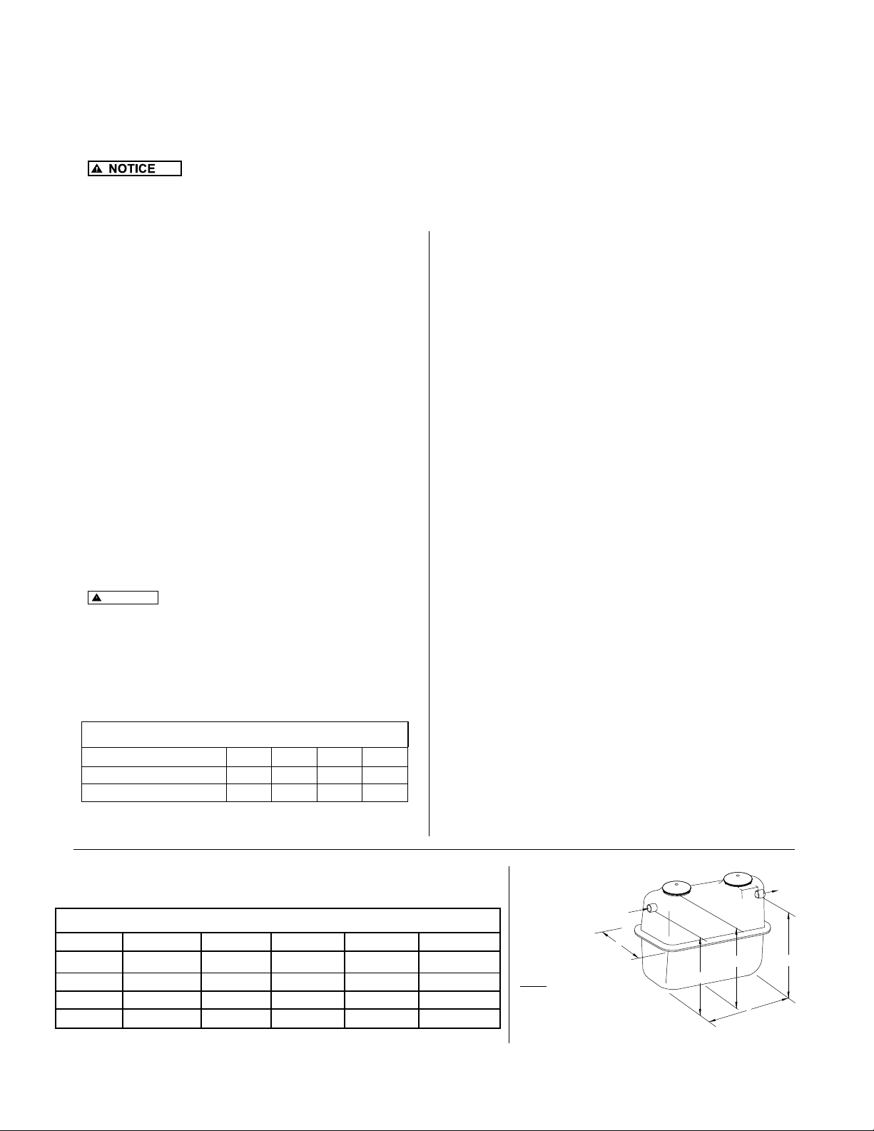
1. Excavate an area large enough for the Fusion® Series unit to be installed. See Figure 5 and Table 2 for the actual dimensions of the unit. In
areas where high groundwater is not a concern, excavation dimensions are calculated by adding 12-18" (305-457 mm) to the length and width
of the Fusion®. This will allow sufcient room for proper backlling. If it is reasonable to expect a seasonally high water table, consult the AntiFlotation Procedures section below.
2. Construct a 6" (152 mm) thick stone pad of either 1/4" - 1/2" (6-13 mm) diameter stone or concrete pad and level to within 1/8" (3 mm).
3. If the unit is not level, it will cause uneven water ow as well as unbalanced aeration, which will result in poor performance.
4. Gently lift the unit at all four lifting points with a harness and install it on leveled stone pad (Figure 11).
5. Check unit to make certain it is level by placing a level at several locations on the riser. (riser covers removed) (Figure 11).
BACKFILLING
1. If groundwater is present, anti-otation measures must be used to
stabilize the unit prior to backlling. Please follow the procedures
in the Anti-otation section to properly anchor the Fusion
2. Fill the unit with clean water to the normal operating depth prior to
backlling. Partition walls between chambers are water-tight and will
ll in succession beginning on the inlet side of the unit. Therefore,
it is best to alternate chambers when lling with water so the unit
remains level. Check for leakage around the unit.
3. See riser instructions page 7. See Table 1 for number and size of
access openings. Riser extensions are available for deeper burial.
Make certain risers are sealed properly and watertight.
4. Install riser covers.
5. Backll with good quality granular soil around the unit that is free
of organic matter, rock, stone, tree roots, or other debris that could
damage the unit. Unit can be backlled partially before risers are
installed to aid in riser installation.
6. Tamp soil around perimeter of the unit as it is backlled to stabilize
the unit and to reduce settling.
7. Finalize backll with a mounded contour so that surface water is
shed away from the unit. Under no circumstances should surface
water be allowed to accumulate around unit.
8.
CAUTION
MAXIMUM soil burial depth over the unit is 36
inches (914 mm).
Table 1
NUMBER OF ACCESS RISERS IN FUSION® SERIES
ZFL-2800 ZFL-3200 ZFL-3600 ZFL-4000
24" (61 cm) Diameter 3 3 3 3
26.5" (67.3 cm) x 45" (114.3 cm) 1 1 1 1
®.
COLD WEATHER INSTALLATION
When installing Fusion® in cold climates, the blower must be protected
from snow drifts by installing it either inside a garage, home, basement,
crawlspace or riser. If installed in a riser, the blower must be protected
from inundation and must have a vent pipe installed to above the
maximum snow depth with a 180 degree angle at the end to prevent
snow and water entry. Also, the top and sides of the Fusion® must be
insulated with insulation sheeting or other means to provide a minimum
insulation value of R-8, along with the risers and lids. Please contact
the factory for further information.
ANTI-FLOTATION PROCEDURES
It is necessary to anchor the Fusion® in high ground water conditions to
prevent otation. If groundwater rises above the rock or concrete pad
that the Fusion® sits on, anchoring is required. Please consult a design
engineer, soil scientist or other qualied individual to determine high
groundwater conditions.
1. Follow the procedures outlined in the Excavation and Installation
Section items 1-5 to properly prepare and level the Fusion®
excavation.
2. Follow the procedures outlined in the Backlling Section items 1-4
to properly ll the Fusion® with water and add risers if needed.
3. Refer to Figure 12, Anchoring Schematic to determine the
minimum amount of backll to be placed around the Fusion® in the
excavation. Tamp the ll to prevent settling.
4. Refer to Table 3, Concrete Anchoring Dimensions to determine
the amount of concrete needed for the concrete anchor collar that
is poured around the entire circumference of the Fusion®. Pour
concrete to the specied dimensions to fully engage the mid-seam
of the Fusion®, which will anchor it once the concrete cures. Make
certain to pour the concrete in a manor to minimize trapped air
within the concrete. Agitating or lightly mixing the concrete with
a metal rod or other similar device once poured will help release
trapped air. Be careful not to puncture or crack the unit.
5. Allow the concrete to harden before nal backlling.
6. Complete the procedures outlined in the Backlling Section,
items 5-8.
Table 2
FUSION® DIMENSIONS
SYSTEM L W H I E
ZFL-2800 14' 8" (4.5 m) 7' 0" (2.1 m) 7' 10" (2.4 m) 6' 1" (1.9 m) 5' 7" (1.7 m)
ZFL-3200 15' 0" (4.6 m) 7' 5" (2.3 m) 7' 10" (2.4 m) 6' 1" (1.9 m) 5' 7" (1.7 m)
ZFL-3600 15' 5" (4.7 m) 7' 9" (2.4 m) 8' 0" (2.4 m) 6 '3" (1.9 m) 5' 9" (1.8 m)
ZFL-4000 15' 6" (4.7 m) 8' 0" (2.4 m) 8' 4" (2.5 m) 6' 7" (2.0 m) 6' 1" (1.9 m)
© Copyright 2013. All rights reserved.
6
Figure 5- Dimensions
INLET
W
NOTES:
1) DIMENSIONS "I" AND "E" ARE TO THE BOTTOM
OF THE INLET/OUTLET PIPE.
2) THE OVERALL HEIGHT DIMENSION "H" IS TO THE
TOP OF THE NARROW ADAPTER RING, NOT THE RISER LID.
3) A RISER COVER COMES STANDARD. ADDITIONAL RISERS ARE
PURCHASED SEPERATELY.
OUTLET
H
I
E
L
sk2624
 Loading...