

Page 1
Page 2

Report number: 0397PS001S
Tested to ULI482-2011
CST & CSS Models
Owners Manual
Installation and Operating Instructions
Revision A.8.2 Jan. 6, 2015
Clarry Pellet Stove, LLC
P.O. Box 2097
Battle Ground, WA 98604
1-844-4CLARRY
Clarry® Pellet Stove
This product is patented under US Patent #8020547
and Canadian Patent # CA2604313
Made in the USA
Clarry® is a registered trademark of Clarry Pellet Stove, LLC
2.
Page 3
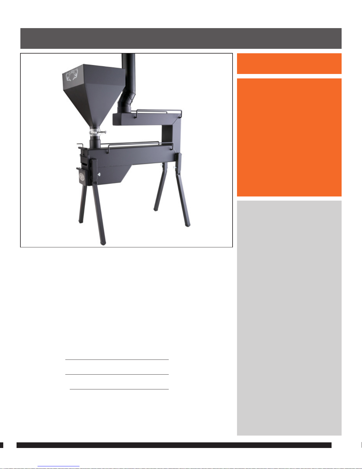
NOT FOR USE IN
MANUFACTURED HOMES,
MOBILE HOMES, MOTOR HOMES
OR CAMPING TRAILERS.
INTENDED USE MAY
INCLUDE RESIDENTIAL HOMES,
TENTS, HUNTING CABINS OR LINE
SHACKS, ICE FISHING HOUSES
AND DETACHED SHOP
STRUCTURES WHERE ELECTRICITY
MAY NOT BE AVAILABLE.
We welcome you as a new owner of the Clarry® Pellet Stove, CST or
CSS model. This manual will explain the installation, operation and
maintenance of this pellet-burning heater. Please familiarize yourself
with this Owner’s Manual before operating your stove and save it for
future reference. We offer our continual support and guidance to help
you achieve the maximum benefit and enjoyment from your stove.
IMPORTANT INFORMATION
No other Clarry® Pellet Stove has the same serial number as yours.
The serial number will be needed in case you require service of any type.
Model: CST/CSS
Serial Number:
Purchase Date:
Purchased From:
To receive full warranty coverage, you will need to show evidence of
the date you purchased your stove. We suggest that you attach your
bill of sale to this page so that you will have all of the information you
need in one place, should the need for service or information occur.
3.
WARNING
INTRODUCTION
PLEASE READ THIS ENTIRE MANUAL
BEFORE INSTALLATION AND USE OF
THIS PELLET
FUEL-BURNING HEATER.
Failure to follow these instructions
could result in property damage,
bodily injury, or even death.
Contact local building or fire
officials about restrictions
and installation inspection
requirements in your area.
INSTALLER: AFTER INSTALLATION,
GIVE THIS MANUAL TO THE
HOMEOWNER AND EXPLAIN
OPERATION OF THIS STOVE.
SAVE THESE INSTRUCTIONS.
Page 4

4.
SAFETY PRECAUTIONS
• Do not operate your stove if you
smell smoke coming from it.
• Use only liquid gel or wax/sawdust fire starter
according to the stove’s operating instructions.
Never use gasoline, gasoline-type lantern fuel,
kerosene, charcoal lighter fluid, or similar liquids to
start or “freshen up” a fire in this heater. Keep all such
liquids well away from the stove while it is in use.
• CAUTION: DO NOT ATTEMPT TO RESTART THE
STOVE WHILE THE STOVE BODY IS STILL HOT. THE
GEL FIRE STARTER MAY VAPORIZE RESULTING IN
FLAME FLARE UP CAUSING BODILY INJURY.
• Never try to repair or replace any part of the stove
unless instructions are given in this manual. All other
work should be done by a trained technician.
• Contact your local building officials to obtain
a permit and information on any installation
restrictions or inspection requirements in your
area. The makers cannot anticipate every possible
method of using the stove. Notify your insurance
company of this stove installation, as well.
• This stove must be properly installed to prevent
the possibility of a structural fire. The instructions
must be strictly adhered to. Do not use makeshift
methods or compromises in the installation.
• The exhaust system must be completely airtight and
properly installed. It is recommended that the stove
vent joints be sealed with high temperature sealant.
• Your stove requires periodic maintenance and
cleaning (see “Maintaining Your Stove”).
• Failure to maintain your stove may lead to smoke spillage.
• Allow the stove to cool before carrying
out any maintenance or cleaning.
• Disposal of Ashes – Ashes should be placed in a steel
container with a tight fitting lid. The closed container
of ashes should be placed on a noncombustible floor
or on the ground, well away from all combustible
material, pending final disposal. If the ashes are
disposed of by burial in soil or otherwise locally
dispersed, they should be retained in the closed
container until all cinders have thoroughly cooled.
• This stove is designed and approved for pelletized
wood fuel only. Any other type of fuel burned in
this stove will void the warranty and safety listing.
• Keep foreign objects out of the hopper.
• Do not place clothing or other flammable
items on or near the stove.
• The exhaust system should be checked at least
twice a year for any build-up of soot or creosote.
• DO NOT TOUCH THE HOT SURFACES OF THE STOVE.
EDUCATE ALL CHILDREN OF THE
DANGER OF A HIGH-TEMPERATURE STOVE.
YOUR CHILDREN SHOULD BE CLOSELY SUPERVISED
WHEN THEY ARE IN THE SAME ROOM AS THE STOVE.
• Clarry Pellet Stove LLC grants no warranty
implied or stated, for the installation or
maintenance of your heater, and assumes no
responsibility for any consequential damages.
• When this heating appliance is not properly
installed, a fire may result. To reduce the risk
of fire, follow the installation instructions.
• Contact local building or fire officials about restrictions
and installation inspection requirements in your area.
Page 5
* Heating capacity will vary
depending on the exterior wall
material, degree of insulation,
and the outside temperature. It
is also affected by the fuel size,
quality, and moisture level.
** Fuel: This unit is designed for
wood pellets that comply with the
standards set by the Association of
the Pellet Fuel Industry (density of
at least 40 lbs. per cubic foot, 1/4”
to 5/16” diameter, length no greater
than 1 ½”, 8200 BTU’s/lb., moisture
under 8% by weight, ash under
1% by weight, and salt under 300
parts per million). If the fuel does
not comply with this standard, the
unit may not operate as designed.
OUR STOVES OPERATE BEST USING
PELLETS WITH <6% MOISTURE
CONTENT. DO NOT REUSE PELLET
FUEL THAT HAS NOT BEEN STORED
IN A MOISTURE PROOF CONTAINER.
PELLETS NOT STORED IN THIS
MANNER MAY DRAW MOISTURE
AND WILL NOT BURN PROPERLY.
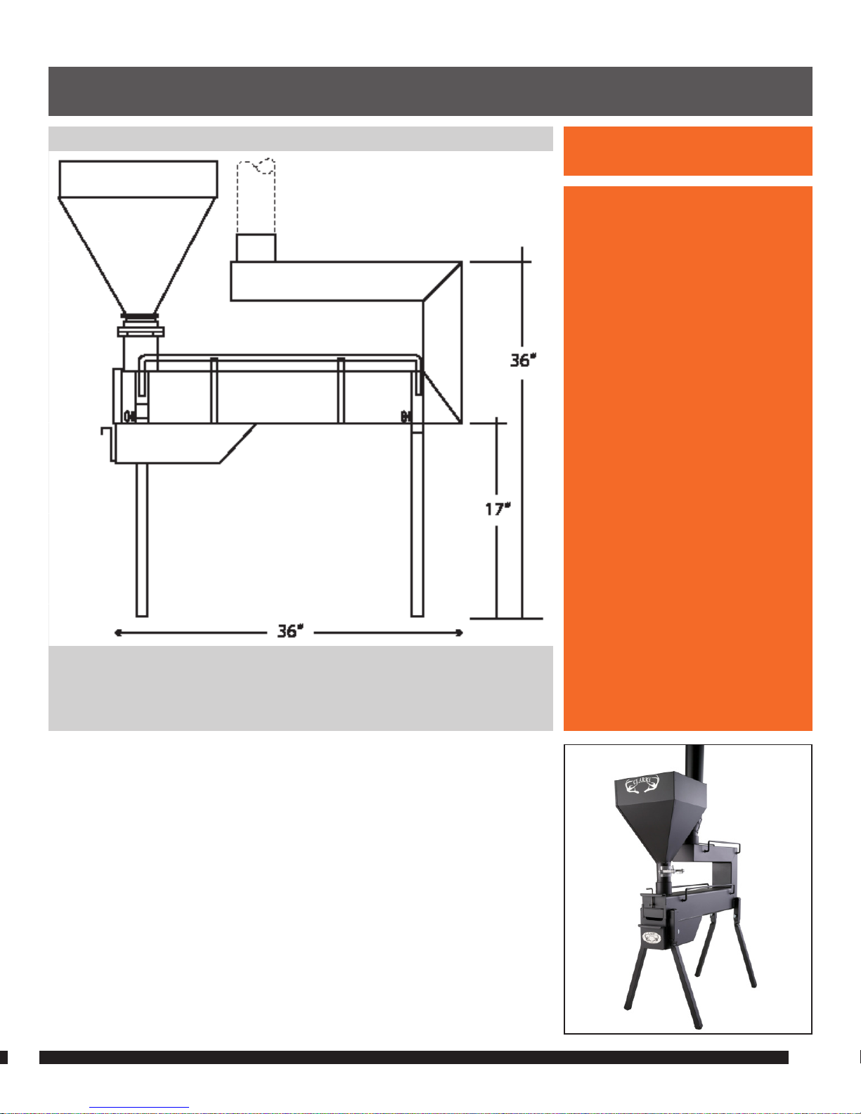
CST HEATING SPECIFICATIONS:
Approximate Maximum Heating Capacity (in square feet): 1000 sq. ft.*
Approximate Burn Rate (pounds per hour): 5.0**
Approximate Burn Time: 8 hours**
Hopper Capacity: 40 pounds
Stove Weight: 100 pounds assembled
5.
Note
1.) DIMENSIONS AND SPECIFICATIONS: CST Model
FIGURE 1 CST MODEL
Page 6

* Heating capacity will vary
depending on the exterior wall
material, degree of insulation,
and the outside temperature. It
is also affected by the fuel size,
quality, and moisture level.
** Fuel: This unit is designed for
wood pellets that comply with the
standards set by the Association of
the Pellet Fuel Industry (density of
at least 40 lbs. per cubic foot, 1/4”
to 5/16” diameter, length no greater
than 1 ½”, 8200 BTU’s/lb., moisture
under 8% by weight, ash under
1% by weight, and salt under 300
parts per million). If the fuel does
not comply with this standard, the
unit may not operate as designed.
OUR STOVES OPERATE BEST USING
PELLETS WITH <6% MOISTURE
CONTENT. DO NOT REUSE PELLET
FUEL THAT HAS NOT BEEN STORED
IN A MOISTURE PROOF CONTAINER.
PELLETS NOT STORED IN THIS
MANNER MAY DRAW MOISTURE
AND WILL NOT BURN PROPERLY.
EPA COMPLIANCE:
The CST and CSS model stoves
are EPA exempt from
Phase II requirements.
6.
Warning
CSS HEATING SPECIFICATIONS:
Approximate Maximum Heating Capacity (in square feet): 500 sq. ft.*
Approximate Burn Rate (pounds per hour): 4.5 lbs/hr.**
Approximate Burn Time: 10 hours**
Hopper Capacity: 40 pounds
Stove Weight: 65 pounds assembled
1.) DIMENSIONS AND SPECIFICATIONS: CSS Model
Note
FIGURE 1.1 CSS MODEL
Page 7

READ THIS ENTIRE MANUAL
BEFORE YOU INSTALL AND USE THE
CLARRY® PELLET STOVE.
PACKING LIST
• CST or CSS Stove Body
• Ash Drawer
• Stainless Steel Grate
• Damper Door and Grate Access Door
• Pellet Hopper
• Owners Manual
• Door Latch Tool
• 4 Legs
• 1 ea. 4”-90° elbow required for Sierra model only to clear hopper
IMPORTANT - THE FOLLOWING MATERIALS NEED TO
BE PURCHASED FOR FINAL ASSEMBLY:
1. Enough 4” 28 gauge black Stove Pipe (D.1) to complete flue installation.
2. One or more 4” 45/90 degree elbows may be needed to complete tent side
wall installations.
3. A directional wind cap may be used at the top of the stove pipe. No other
device, such as a China Hat can be used.
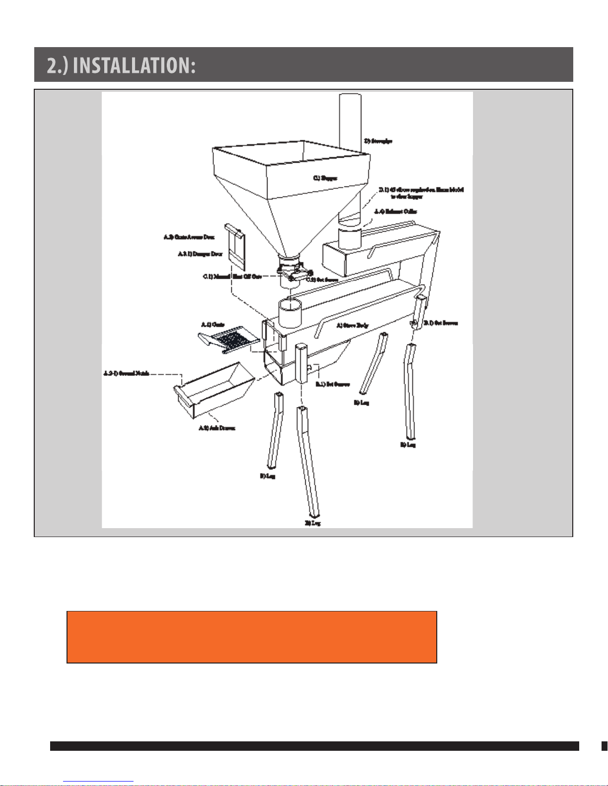
STOVE ELEMENTS (SEE FIGURE 2)
A) Stove Body (A),
which includes the Grate (A.1),
Ash Drawer (A.2),
and Grate Access Door (A.3) with Damper Door (A.3.1)
B) Four (4) Legs (B) and four (4) Set Screws (B.1)
C) Hopper (C). Holds the wood pellets
D) Stove Pipe.
D.1) 1 -Ea. 4” 45/90° elbows required for CSS Model only to clear hopper
7.
Before You Begin
2.) INSTALLATION: Setting up the Stove
Page 8
8.
Assembly
1. Tip the stove body (A) on end, insert the legs (B) and loosely tighten the set screws. (B.1)
2. Move the stove (A) into the upright position. Adjust the legs (B) so that the stove is level. Finish tightening the set screws (B.1).
3. Lift fire chamber access door (A.3) and slide grate (A.1) into the fire chamber in body (A). Push in firmly until it stops
against the pellet delivery chute. Insert damper door (A.3.1) in access door (A.3) guide rails. Close both doors.
4. Insert the 4” 28 gauge sheet metal stove pipe (D) into the 4” exhaust collar in body (A). The CSS Model will require a 4”
45/90° elbow offset to clear the hopper for a vertical installation. Make sure you have the proper configuration for a
ceiling/roof opening or sidewall opening. See FIG. 9, page 17.
5. Put the pellet hopper (C) into the 3” collar in body (A). The manual shut off gate (C.1) should be closed.
WARNING: FAILURE TO FOLLOW THIS PROCEDURE MAY CAUSE THE STOVE TO “OVER FIRE”.
SEE PAGE 18 FOR AN EXPLANATION OF “OVER FIRING”
FIGURE 2
Page 9

NEVER REDUCE THE
MINIMUM CLEARANCE DIMENSIONS
SHOWN
IN FIG. 3.1 AND FIG. 3.2.
• Prior to placing the Clarry® Pellet Stove in your structure, you must
burn the stove in for 20 minutes, to set the stove paint.
• Assemble the stove in an outdoor location according to
the directions above; bring it to operating temperature,
or to the point where the paint stops smoking.
• Make sure that any time you light the stove outdoors the chimney is not
positioned directly under a low hanging tree branch or near a structure.
• Once the stove has been burned in and cooled down, it is ready to install.
INSTALLATION OPTIONS
The Clarry® Pellet Stove is approved for an interior vertical through
the roof installation; horizontal through the wall to exterior vertical
installation and retrofit to existing masonry chimney installation.
NOTE: When using horizontal through the wall installation, floor
protection material must extend under the chimney connector
(the 28 gauge stove pipe) from the back or side of stove to the
wall. Floor protection width must be a minimum 2” wider on each
side of chimney connector, for a total minimum width of 8”.
PRE-INSTALLATION RECOMMENDATION
Sketch out a detailed plan of the installation including dimensions. Then
verify the dimensions with the requirements listed in this manual.
When determining the location of the stove, locate the ceiling trusses
(for vertical penetrations). You may wish to adjust the stove position slightly to
ensure the vent does not intersect with a framing member, but never reduce the
minimum clearance dimensions shown on the next page in FIG. 3.1 and FIG. 3.2.
STOVE PLACEMENT
Place the stove on non-combustible floor protection using wall clearance
dimensions for a straight (Fig. 3.1) or corner installation (Fig. 3.2)
Stove must be placed so that no combustibles are within, or can swing
within (doors, drapes, etc.), 36” of any surface of the stove. Heater
and floor protection must be installed on a level, secure floor.
9.
WARNING
2.) INSTALLATION: “Burning In” the Stove
FIGURE 3.1
FIGURE 3.2
Page 10
The heater must be installed on a non-combustible floor protector extending the full width and depth of the heater
and extending 18” in front beyond the pellet hopper and 8” outside of the legs, minimum 30˝ wide by 56˝ deep.
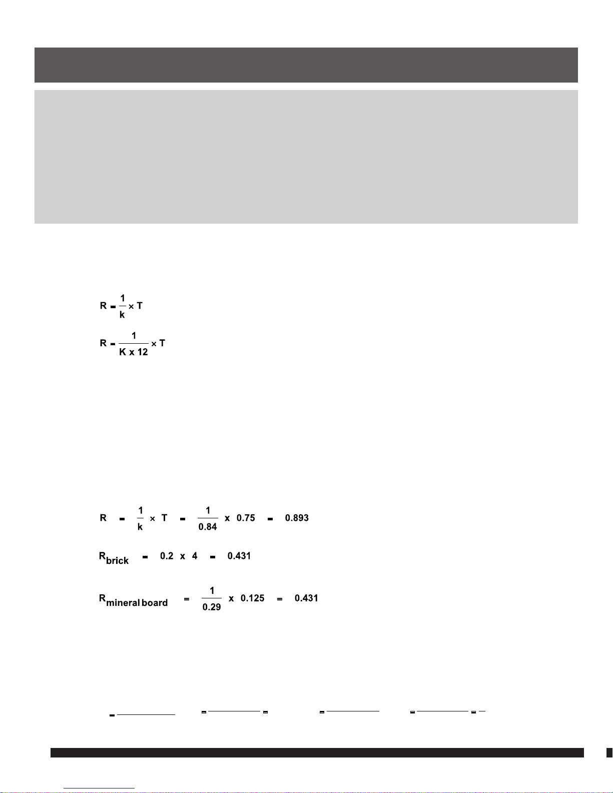
Minimum 1” thick with (k=0.84) (R=1.19) (BTU)(in)/(ft2)(hr)(of ).
How to determine if alternate oor protection materials are acceptable.
All floor protection must be non-combustible (i.e., metals, brick, stone, mineral fiber boards, etc.). Any organic materials
(i.e., plastics, wood paper products, etc.) are combustible and must not be used. The floor protection specified
includes some form of thermal designation such as R-value (thermal resistance) or k-factor (thermal conductivity).
10.
2.) INSTALLATION: Floor Protection Requirements
PROCEDURE
1. Convert specification to R-value:
i. R-value given - no conversion needed.
ii. k-factor is given with a required thickness (T) in inches:
iii. K-factor is given with a required thickness (T) in feet:
iv. r-factor is given with a required thickness (T ) in inches: R = r x T
2. Determine the R-value of the proposed alternate floor protector.
i. Use the formula in step (1) to convert values not expressed as “R”.
ii. For multiple layers, add R-values of each layer to determine overall R-value.
3. If the overall R-value of the system is greater than the R-value of the specified floor protector, the alternate is acceptable.
EXAMPLE: The specified floor protector should be 3/4-inch thick material with a k-factor of 0.84. The proposed alternate is 4”
brick with an r-factor of 0.2 over 1/8” mineral board with a k-factor of 0.29.
Step (a): Use formula above to convert specification to R-value.
Step (b): Calculate R of proposed system. 4” brick of r = 0.2, therefore:
1/8” mineral board of k = 0.29, therefore:
R
TOTA L
= R
BRICK
+ R
MINERAL BOARD
= 0.8 + 0.431 = 1.231
Step (c): Compare proposed system R
TOTA L
of 1.231 to specified R of 0.893. Since proposed system R
TOTA L
is greater than
required, the system is acceptable.
DEFINITIONS
)Fo)(hr)(
2
(ft
R =
12xK
)Fo)(hr)(2ft(
(Btu)(in)
k ==
)Fo)(hr)(2ft(
(Btu)(ft)
K =
k
1
)in)(Btu(
)Fo)(hr)(
2
(ft
r =
=
Page 11
DO NOT CONNECT THE STOVE VENT TO
A VENT SERVING ANY OTHER APPLIANCE OR STOVE.
DO NOT INSTALL A FLUE
DAMPER IN THE EXHAUST VENTING
SYSTEM OF THIS UNIT.
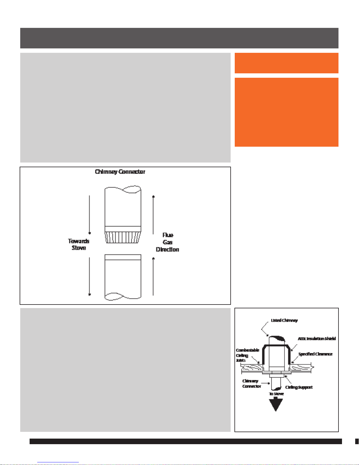
SEE FIG. 4, FIG.5, FIG.6, FIG. 7, FIG. 8, AND FIG. 9
• This stove must be connected to:
1) A chimney complying with the requirements for type HT Chimneys
in the standard for Chimneys, Factory-Built, Residential Type and
Building Heating appliance, UL 103,
OR,
2) A code –approved masonry chimney with a flue liner.
• A source of fresh air into the room must be provided.
• Stove vent must maintain a minimum 36” clearance to any
combustible material or at clearance specified by the vent
manufacturer if the requirement is greater than 36”.
• Do not connect the stove vent to a vent serving any other appliance or stove.
• Do not install a flue damper in the exhaust venting system of this unit.
STOVE VENT TYPE
• Four inch (4”) 28 gauge sheet metal single wall stove pipe.
INSTALLING THE STOVE VENT
• Sealing each vent section by injecting a liberal amount of high
temperature sealant into the gap between sections is recommended.
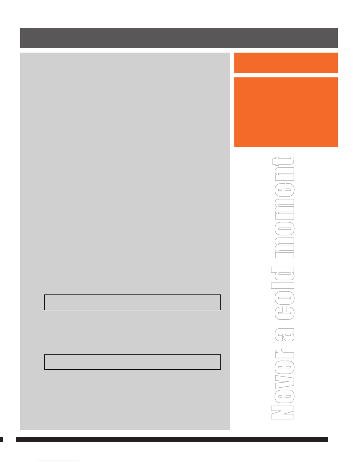
• Insert stove pipe (D) into the 4” vent collar on the stove body (A)
and fasten with 3 sheet metal screws. See FIG. 4. The CSS Model
will require a 4” 45/90° elbow offset to clear the hopper.
• Use a listed ceiling support/fire stop spacer when passing
through combustible ceiling framing (see FIG. 5 and FIG. 7).
CHECK LOCAL BUILDING CODES FOR SPECIFIC REQUIREMENTS.
• Interior installations, with no ceiling, may pass through a framed opening
maintaining a minimum 18” clearance from combustible materials (see FIG 8).
• Use a listed wall thimble when passing the stovepipe horizontally
through combustible materials (see FIG. 6 and 9).
CHECK LOCAL BUILDING CODES FOR SPECIFIC REQUIREMENTS.
• Use no more than 180 degrees of elbows (two 90 degrees, or two 45
degree and one 90 degree elbow, etc.) Maximum horizontal run is 36”.
• Consult your local building codes for clearances, thimbles
and connections required when connecting the Clarry
Pellet Stove to an exiting or new masonry chimney.
11.
WARNING
2.) INSTALLATION: Venting Requirements
Page 12
DO NOT CONNECT THIS
UNIT TO A CHIMNEY FLUE SERVING
ANOTHER APPLIANCE.
DO NOT CONNECT TO ANY
AIR DISTRIBUTION DUCT
OR SYSTEM.
FACTORY BUILT CHIMNEY
When a metal prefabricated
chimney is used, the manufacturer’s
installation instructions must be
followed. You must also purchase
(from the same manufacturer)
and install the ceiling support
package or wall pass-through and
“T” section package, fire stops
(where needed), insulation shield,
roof flashing, etc. Maintain proper
clearance to the structure as
recommended by the manufacturer.
The chimney must be the required
height above the roof or other
obstructions for safety and proper
draft operation. See page 14 for
chimney termination requirements.
The chimney connector is a single walled pipe used to connect the stove to
the chimney. For use with the Clarry® Pellet Stove, the chimney connector
MUST be 4” in diameter, with a minimum thickness of 28 gauge black steel.
Aluminum and galvanized steel pipe is not acceptable for use with the
Clarry® Pellet Stove. These materials cannot withstand the extreme
temperatures of a wood pellet fire and can give off toxic fumes when heated.
DO NOT USE THE CONNECTOR PIPE AS A CHIMNEY.
Each chimney connector or stove pipe section must be installed to the stove
flue collar and to each other with the male (crimped) end toward the stove.
See FIG 4.
This prevents any amount of condensed or liquid creosote from running down the outside of the pipe or the stove top. All joints, including the flue collar connection must be secured with three sheet
metal screws to ensure that the sections do not separate.
For the best performance the chimney connector should be as short and direct
as possible, with no more than two 90° elbows. The maximum horizontal run
is 36” and a recommended total length of stove pipe should not exceed 10
feet. Always slope horizontal runs upward ¼” per foot toward the chimney.
No part of the chimney connector may pass through an attic or roof space,
closet or other concealed space, or through a floor ceiling. All sections of
the chimney connectors must be accessible for cleaning. Where passage
through a wall or partition of combustible construction is desired, the installation must conform to NFPA 211, and is also addressed in this manual.
12.
WARNING
2.) INSTALLATION: Chimney Connection
FIGURE 4
FIGURE 5
Page 13
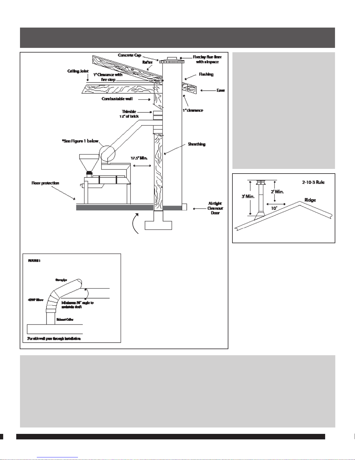
CHIMNEY HEIGHT TYPICAL FOR ALL
INSTALLATIONS
A masonry chimney or a listed
factory-build chimney must be the
required height above the roof and
any other nearby obstructions. The
chimney must be at least 3’ (90 cm)
higher than the highest point where
it passes through the roof and at
least 2’ (60 cm) higher than the
highest part of the roof or structure
that is within 10’ (305 cm) of the
chimney, measured horizontally.
13.
2.) INSTALLATION: Chimney Connection
FIGURE 6
MASONRY CHIMNEY
Ensure that a masonry chimney meets the minimum standards of the National Fire Protection Association (NFPA) by having it
inspected by a professional. Make sure there are no cracks, loose mortar or other signs of deterioration and blockage. Have
the chimney cleaned before the stove is installed and operated. When connecting the stove through a combustible wall to a
masonry chimney, special methods are needed. Refer to Combustible Wall Chimney Connector Pass-Throughs on page 14.
See note page 9 for floor
protection extention under
chimney connector.
Page 14
DO NOT TERMINATE THE CLARRY
PELLET STOVE VENT PIPE HORIZONTALLY.
CHIMNEY TERMINATION
• Must have a directional wind cap
(to prevent water from entering).
• Minimum 3’ clearance from any forced
air intake of any other appliance.
• Minimum 1’ clearance horizontally from
combustible wall.
• Must be a minimum of 3´ above the
roof, or 2´ above the roof ridgeline with
10´ of roof penetration.
• Minimum 5’ clearance from any
door opening.
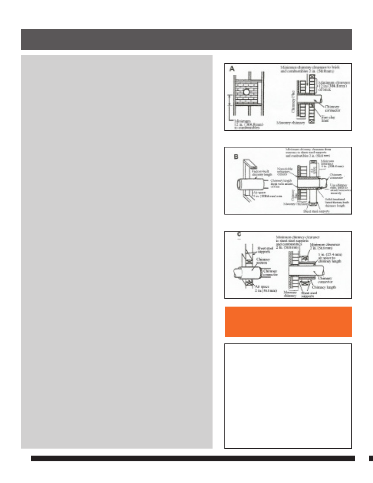
COMBUSTIBLE WALL CHIMNEY CONNECTOR PASS-THROUGHS
METHOD A.
12” (304.8 mm) Clearance to Combustible Wall Member: Using a
minimum thickness 3.5” (89 mm) brick and a 5/8” (15.9 mm) minimum
wall thickness clay liner, construct a wall pass-through. The clay liner
must conform to ASTM C315 (Standard Specification for Clay Fire
Linings) or its equivalent. Keep a minimum of 12” (304.8 mm) of brick
masonry between the clay liner and wall combustibles. The clay liner
shall run from the brick masonry outer surface to the inner surface
of the chimney flue liner but not past the inner surface. Firmly
grout or cement the clay liner in place to the chimney flue liner.
METHOD B.
9” (228.6 mm) Clearance to Combustible Wall Member: Using a 4”
(152.4 mm) inside diameter, listed, factory-built solid-pak chimney
section with insulation of 1” (25.4 mm) or more, build a wall passthrough with a minimum 9” (228.6 mm) air space between the
outer wall of the chimney length and wall combustibles. Use sheet
metal supports fastened securely to wall surfaces on all sides, to
maintain the 9” (228.6 mm) air space. When fastening supports to
chimney length, do not penetrate the chimney liner (the inside wall
of the solid-pak chimney). The inner end of the solid-pak chimney
section shall be flush with the inside of the masonry chimney
flue, and sealed with a non-water soluble refractory cement. Use
this cement to also seal to the brick masonry penetration.
METHOD C.
2” (50.8 mm) Clearance to Combustible Wall Member: Start with
a solid-pak listed factory built chimney section at least 12” (304
mm) long, with insulation of 1” (25.4 mm) or more, and an inside
diameter of 6” (2 inches [51 mm] larger than the 4” [152.4 mm]
chimney connector). Use this as a pass-through for a minimum
24-gage single wall steel chimney connector. Keep solid-pak
section concentric with and spaced 1” (25.4 mm) off the chimney
connector by way of sheet metal support plates at both ends
of chimney section. Cover opening with and support chimney
section on both sides with 24 gage minimum sheet metal supports.
See that the supports are fastened securely to wall surfaces on
all sides. Make sure fasteners used to secure chimney flue liner.
NOTES:
1. Connectors to a masonry chimney, excepting method B, shall
extend in one continuous section through the wall pass-through
system and the chimney wall, to but not past the inner flue liner face.
2. A chimney connector shall not pass through an attic or roof
space, closet or similar concealed space, or a floor, or ceiling.
14.
Section2.) INSTALLATION: Chimney Connection
METHOD C.
METHOD B.
METHOD A.
Page 15
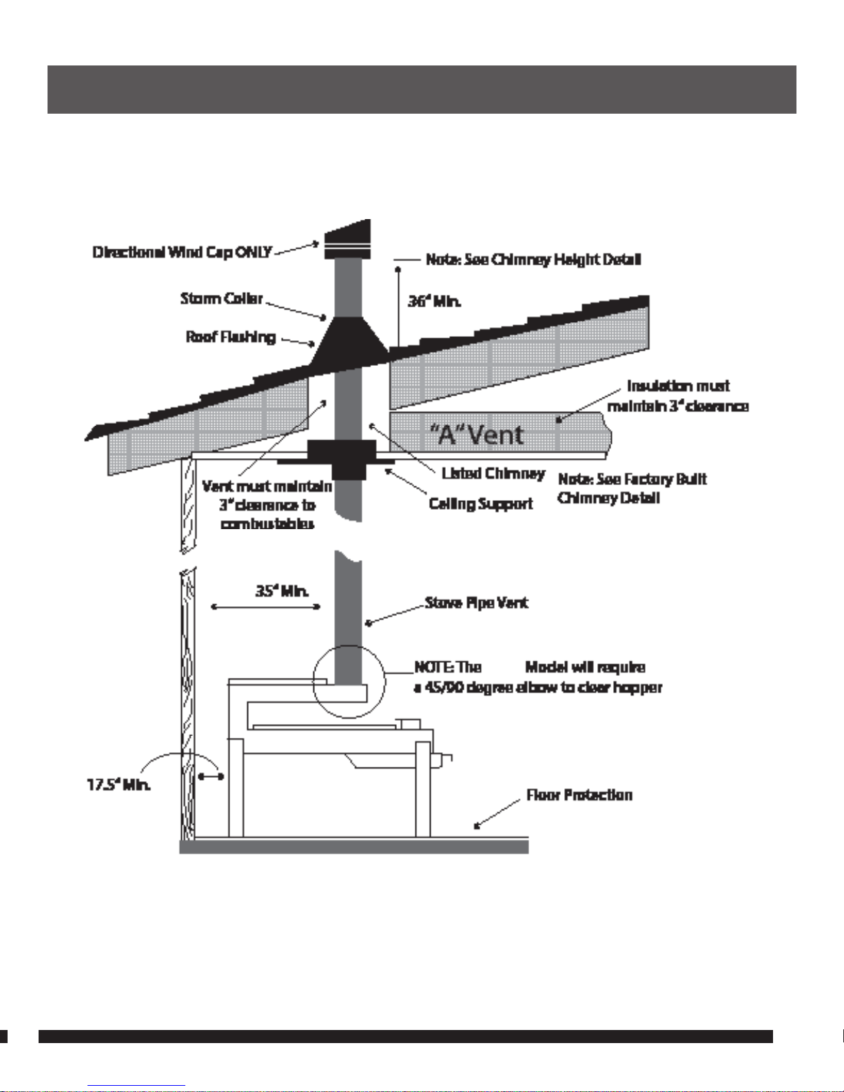
15.
2.) INSTALLATION: Interior Vertical Installations
FIGURE 7
CSS
Page 16
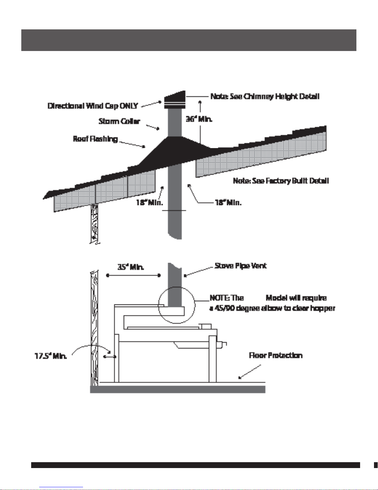
16.
2.) INSTALLATION: Interior Vertical Installations
FIGURE 8
CSS
Page 17
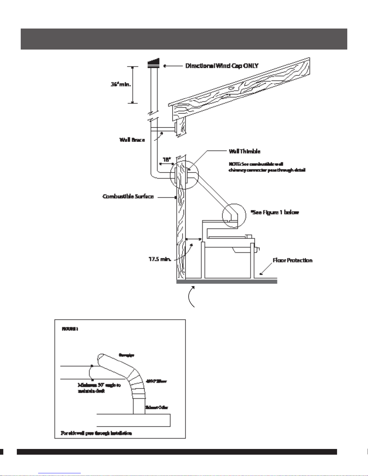
17.
2.) INSTALLATION: Interior Horizontal Installation
FIGURE 9
See note page 9 for floor
protection extention under
chimney connector.
Page 18

NEVER USE GASOLINE, GASOLINE-TYPE
LANTERN FUEL, KEROSENE, CHARCOAL
LIGHTER FLUID, OR SIMILAR LIQUIDS
TO START OR “FRESHEN UP” A FIRE IN
THIS STOVE. KEEP ALL SUCH LIQUIDS
WELL AWAY FROM THE STOVE WHILE
IT IS IN USE.
WARNING: FAILURE TO FOLLOW THIS
PROCEDURE CAN LEAD TO “OVER
FIRING” THE STOVE. IF THE SIDES OF
THE FIRE CHAMBER GLOW CHERRY
RED, THE STOVE IS BEING “OVER
FIRED”! “OVER FIRE” CAN CAUSE
DAMAGE TO THE STOVE,
AND MAY RESULT IN
CAUSING A FIRE AT THE
SURROUNDING SURFACES.
OPERATING INSTRUCTIONS REFER TO FIGURE 2.)
1. Fill the hopper (C) with one 40-lb. bag of “PREMIUM or Super Premium” pellets.
This unit is designed for wood pellets that comply with the standards set by
the Association of the Pellet Fuel Industry (density of at least 40 lbs. per cubic
foot, 1/4” to 5/16” diameter, length no greater than 1 ½”, 8200 BTU’s/lb., moisture
under 8% by weight, ash under 1% by weight, and salt under 300 parts per
million). If the fuel does not comply with this standard, the unit may not operate
as designed. Our stoves operate best using pellets with <6% moisture content.
2. Open the shut off gate (C.1), allowing the pellets to drop into position in the
firebox. Note: Tighten the setscrew (C.2) in the shut off gate to avoid misplacing
the shut off gate (C.1).
3. Next, open the ash drawer (A.2). A few pellets will have fallen through the
fire grate. That’s OK. Squeeze a liberal amount of liquid gel fire starter, or stack
several wax/sawdust fire sticks into the drawer, aiming at the center of the
drawer. Light it with a match, then push the drawer in until you reach the
first notch (A.2-2), the fire starting position and push the door (A.3) into the
notch. This is also the final burning position and will allow some air control
for the fire. Make sure damper door (A.3.1) completely covers the opening in
grate access door. (.3)
WARNING: FAILURE TO FOLLOW THIS PROCEDURE WILL LEAD TO “OVER FIRING” THE
STOVE. IF THE SIDES OF THE FIRE CHAMBER GLOW CHERRY RED, THE STOVE IS BEING
“OVER FIRED”! “OVER FIRE” CAN CAUSE DAMAGE TO THE STOVE, AND MAY RESULT IN
CAUSING A FIRE AT THE SURROUNDING SURFACES.
4. Air Control – The stove will reach maximum heating capacity with the Damper
Door (A.3.1) closing off the control air opening. Once the stove has reached
full heating capacity, begin to slide the Damper Door (A.3.1) up exposing the
opening in the Grate Access Door (A.3). Adjust to personal comfort. Exposing
the entire 1” x 5” opening allows the stove to operate at a much
lower temperature.
5. As fuel is consumed, pellets will continue to slide down into the firebox and
your fire will continue to burn. One 40-lb. bag will burn for approximately
eight (8) hours.
18.
WARNING
3.) OPERATION: Operating Instructions
Page 19

DANGER: FIRE HAZARD AND CARBON
MONOXIDE HAZARD
HEAT OUTPUT
Temperatures exceeding 900 degrees in the fire chamber and 500 degrees at the
heat exchanger are reached in 15 minutes. Do not touch the stove, or place any
combustible materials within 36 inches.
DANGER – Fire Hazard/Carbon Monoxide Hazard
1. This stove may start other fires. Never operate this stove in places without a
fresh air source or in places that contain or may contain volatile and inflammable
liquids or vapors. Never operate this stove where airborne combustibles or
products such as gasoline, solvents, paint thinners, or unknown chemicals may
be found.
2. This stove consumes air (oxygen) and produces carbon monoxide. Using this
product in unventilated or enclosed areas, without a source of fresh air make up,
may cause injury or death.
3. Carbon Monoxide poisoning may be accompanied by symptoms such as
watery eyes, fatigue and dizziness. If you experience these symptoms while
using this product, get fresh air immediately.
4. Ensure the stove fire is out and cool before emptying the contents. Pellet embers
and ash can smolder and remain very hot for a long period time without smoke.
5. Ashes should be placed in a metal container with a tight fitting lid. The closed
container of ashes should be placed on a noncombustible surface or on the
ground, well away from all combustible materials, pending final disposal. If the
ashes are disposed of by burial in soil or otherwise locally disposed, they
should be retained in the closed container until all cinders have been
thoroughly cooled.
SHUTTING DOWN THE STOVE
1. Close the manual shut off gate (C.1) to keep any more pellets from sliding into
the firebox. Re-tighten the set screw (C.2). The fire should go completely out in
about 20 minutes.
2. Ensure the stove fire is out and cool before emptying the contents.
Using the Door Latch Tool provided, remove the ash drawer to empty the ashes.
3. It is important to leave the Ash Drawer (A.2) open in the operating position
notch (A.2-1) to allow air to continue to enter the firebox until the fire has
completely burned all of the pellets. Closing the ash drawer prior to completely
burning all of the pellets may cause the fire to smolder and put smoke into your
shelter due to lack sufficient air to completely burn all of the remaining pellets.
SEE MAINTENANCE INSTRUCTIONS THAT FOLLOW, FOR PROPER
DISPOSAL OF ASHES.
19.
WARNING
3.) OPERATION: Operating Instructions
Page 20

CLEANING THE STOVE WHEN YOU’RE USING IT FOR AN EXTENDED PERIOD IS
EXTREMELY IMPORTANT.
1. After every use, remove the ash from the ash drawer.
Note: Ashes should be placed in a metal container with a tight fitting lid. The
closed container of ashes should be placed on a noncombustible floor or on the
ground, well away from all combustible materials, pending final disposal. If the
ashes are disposed of by burial in soil or otherwise locally dispersed, they should
be retained in the closed container until all cinders has been thoroughly cooled.
2. Remove the grate daily and clean it with a wire brush.
3. Soot and Fly-ash: Formation and Need for Removal. The products of
combustion will contain small particles of fly-ash. The fly-ash will collect in
the exhaust venting system and restrict the flow of the flue gases. Incomplete
combustion, such as occurs during startup, shutdown, or incorrect operation
of the stove will lead to some soot formation which will collect in the exhaust
venting system. The exhaust venting system should be inspected at least twice
every year to determine if cleaning is necessary.
4. Creosote: Formation and Need for Removal. When wood is burned slowly, it
produces tar and other organic vapors, which combine with expelled moisture
to form creosote. The creosote vapors condense in the relatively cool chimney
flue of a slow-burning fire. As a result, creosote residue accumulates on the flue
lining. When ignited, this creosote makes an extremely hot fire.
5. The chimney and chimney connector should be inspected at least once every
two months during the heating season to determine if a creosote buildup has
occurred. If it has accumulated, it should be removed to reduce the risk of a
chimney fire.
20.
4.) MAINTAINING THE STOVE
Page 21

Clarry® Pellet Stove LLC warrants to the original retail purchaser of a Clarry® Stove that the stove is free from defects in
material and workmanship. This warranty extends only to the original retail purchaser of a Clarry® Stove, is not transferable,
and shall expire one year after the date of the original retail purchase of the stove. If a defect in material or workmanship
is discovered in the stove or any of its components during the one year warranty period, Clarry® will, at its option, either: (i)
repair or replace the stove or the component; or (ii) refund the purchase price of the stove. If Clarry® determines to replace
a defective stove or component of the stove, it will do so with a new or re-manufactured stove or component. If the
original stove or component which is defective is no longer available, Clarry®, at its option, will replace the defective stove or
component with a similar stove or component of equal or greater value.
THE ABOVE WARRANTY IS THE EXCLUSIVE WARRANTY GIVEN FOR THE CLARRY® STOVE. THERE ARE NO OTHER WARRANTIES
APPLICABLE TO THE CLARRY® STOVE, EXPRESS OR IMPLIED.
Keep the original sales receipt, as proof of purchase is required to obtain warranty service. The warranty does not extend
to normal wear and tear of the stove or its components or damage to the stove or its components caused by: (i) negligent
use or misuse of the stove or its components; (ii) use of the stove or components contrary to the operating instructions; (iii)
disassembly, repair or alteration of the stove or its components by anyone other than Clarry®; or (iv) natural disasters, such
as fire, flood, etc. Clarry® shall in no event be liable to a purchaser of the stove or any third party for consequential, indirect
or incidental damages of any type, kind or nature, or for damage to or failure of other equipment, caused by a defect in the
stove or component thereof.
Clarry® is a registered Trademark of Clarry Pellet Stove, LLC
Clarry Pellet Stove, LLC
P.O. Box 2097
Battle Ground, WA 98604
1-844-4CLARRY
21.
5.) WARRANTY
Page 22
Page 23

Clarry Pellet Stove, LLC
P.O. Box 2097
Battle Ground, WA 98604
1-844-4CLARRY
Clarry® Pellet Stove
This product is patented under US Patent #8020547
and Canadian Patent # CA2604313
Made in the USA
Clarry® is a registered trademark of Clarry Pellet Stove, LLC
Page 24
1.
MODELS RE & RME FOR OUTDOOR ADVENTURES
Page 25
2.
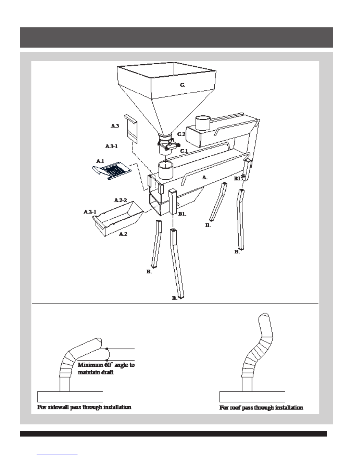
1.) SETTING UP THE STOVE
FIGURE 1
RME MODEL ONLYAPPLIES TO RE & RME MODELS
Page 26

IMPORTANT: THE EXHAUST PIPE
(D.) MUST EXTEND A MINIMUM OF
TWO (2) FEET ABOVE THE HIGHEST
POINT OF THE TENT (STRUCTURE)
TO MAINTAIN PROPER DRAFT,
REGARDLESS OF A ROOF PASS
THROUGH OR SIDEWALL PASS
THROUGH INSTALLATION. DO NOT
PUT ANY KIND OF A WEATHER CAP ON
TOP THE FLUE, AS IT WILL RESTRICT
DRAFT FLOW. NOT FOLLOWING THIS
PROCEDURE WILL CAUSE THE STOVE
TO NOT BURN PROPERLY AND MAY
FORCE SMOKE FROM THE STOVE
INTO YOUR TENT OR STRUCTURE.
STOVE ELEMENTS
A.) Stove body (A), which includes the grate (A.1), ash drawer
(A.2), and grate access door (A.3) with damper door (A.3.1)
B.) Four (4) legs (B) and four (4) set screws (B.1)
C.) Hopper (C). Holds the wood pellets
D.) Two (2) each 4”, 45/90° elbows (D.1) for the RME only.
IMPORTANT- THE FOLLOWING MATERIALS NEED TO
BE PURCHASED FOR FINAL ASSEMBLY:
1. 4” 28 gauge black stovepipe. (D)
2. One or more 4” 45/90 ° elbows for tent sidewall fire boot locations.
3. A directional wind cap may be used at the top of the
stovepipe to eliminate snow or rain entering the stovepipe.
No other device, such as a China hat can be used.
ASSEMBLY
1. Tip the stove body (A) on end, insert the legs (B)
and loosely tighten the set screws (B.1)
2. Move the stove (A) into the upright position. Adjust the legs (B) so
that the stove is level. Finish tightening the setscrews (B.1).
3. Lift fire chamber access door (A.3) and slide grate (A.1) into the fire chamber
in body (A). Push in firmly until it stops against the pellet delivery chute.
WARNING: FAILURE TO FOLLOW THIS PROCEDURE
MAY CAUSE THE STOVE TO “OVER FIRE”.
4. Insert the stovepipe (D) into the 4” 45/90º elbow (D.1) in the
exhaust collar (A.4) on body (A). Make sure you have the proper
configuration for a ceiling/roof opening or sidewall opening.
5. Put the pellet hopper (C) into the 3” collar on body (A). The
manual shut off gate (C.1) should be closed.
IMPORTANT: The exhaust pipe (D.) must extend a minimum of two (2) feet
above the highest point of the tent (structure) to maintain proper draft,
regardless of a roof pass through or sidewall pass through installation.
Do not put any kind of a weather cap on top the flue, as it will restrict
draft flow. Not following this procedure will cause the stove to not burn
properly and may force smoke from the stove into your tent or structure.
3.
WARNING
1.) SETTING UP THE STOVE
WARNING: FAILURE TO FOLLOW THIS PROCEDURE WILL LEAD TO “OVER FIRING”
THE STOVE. IF THE SIDES OF THE FIRE CHAMBER GLOW CHERRY RED, THE STOVE
IS BEING “OVER FIRED”! “OVER FIRE” CAN CAUSE DAMAGE TO THE STOVE,
AND MAY RESULT IN CAUSING A FIRE AT THE SURROUNDING SURFACES.
WARNING: FAILURE TO FOLLOW
THIS PROCEDURE WILL LEAD TO
“OVER FIRING” THE STOVE. IF THE
SIDES OF THE FIRE CHAMBER GLOW
CHERRY RED, THE STOVE IS BEING
“OVER FIRED”! “OVER FIRE” CAN
CAUSE DAMAGE TO THE STOVE, AND
MAY RESULT IN CAUSING A FIRE AT
THE SURROUNDING SURFACES.
Page 27

CAUTION: NEVER USE GASOLINE,
GASOLINE-TYPE LANTERN FUEL,
KEROSENE, CHARCOAL LIGHTER FLUID,
OR SIMILAR LIQUIDS TO START OR
“FRESHEN UP” A FIRE IN THIS STOVE.
KEEP ALL SUCH LIQUIDS WELL AWAY
FROM THE STOVE WHILE IT IS IN USE.
WARNING: FAILURE TO FOLLOW
THIS PROCEDURE WILL LEAD TO
“OVER FIRING” THE STOVE. IF THE
SIDES OF THE FIRE CHAMBER GLOW
CHERRY RED, THE STOVE IS BEING
“OVER FIRED”! “OVER FIRE” CAN
CAUSE DAMAGE TO THE STOVE, AND
MAY RESULT IN CAUSING A FIRE AT
THE SURROUNDING SURFACES.
WARNING: NEVER LEAVE A BURNING
STOVE IN YOUR TENT UNATTENDED.
OPERATING INSTRUCTIONS: SEE FIGURE 1
1. Fill the hopper (C) with one 40-lb. bag of “PREMIUM or Super Premium” grade
pellets. This unit is designed for wood pellets that comply with the standards
set by the Association of the Pellet Fuel Industry (density of at least 40 lbs. per
cubic foot, 1/4” to 5/16” diameter, length no greater than 1 ½”, 8200 BTU’s/lb.,
moisture under 8% by weight, ash under 1% by weight, and salt under 300
parts per million). If the fuel does not comply with this standard, the unit may
not operate as designed. Our stoves operate most efficiently using pellets with
<6% moisture content. Operating the stoves at elevations above 5,000 feet
may require “Super Premium” pellets with <4%, or <2.5% as elevations increase.
2. Fully open the shut off gate (C.1), allowing the pellets to
drop into position in the firebox. Note: Tighten the setscrew
(C.2) to avoid misplacing the shut off gate (C.1).
3. Next, open the ash drawer (A.2). A few pellets will have fallen through the
fire grate. That’s OK. Place several waterproof wax and sawdust fire sticks
(such as Coghlans) in drawer. Light with a match, then push the drawer
in until you reach the first notch (A.2-2), the fire starting position. Make
sure the grate access door (A.3) fits into the notch and the damper door
(A.3.1) completely covers the opening in the grate access door (A.3).
CAUTION: NEVER USE GASOLINE, GASOLINE-TYPE LANTERN FUEL,
KEROSENE, CHARCOAL LIGHTER FLUID, OR SIMILAR LIQUIDS TO
START OR “FRESHEN UP” A FIRE IN THIS STOVE. KEEP ALL SUCH
LIQUIDS WELL AWAY FROM THE STOVE WHILE IT IS IN USE.
4. Once the fire is burning, but always within 5 minutes, close ash
drawer (A.2) down to the second notch (A.2-1) and push the door
(A.3) firmly into the notch. This is the final burning position and will
allow some air control for the fire. Make sure damper door (A.3.1)
completely covers the opening in grate access door. (A.3)
WARNING: FAILURE TO FOLLOW THIS PROCEDURE WILL LEAD TO “OVER FIRING”
THE STOVE. IF THE SIDES OF THE FIRE CHAMBER GLOW CHERRY RED, THE STOVE
IS BEING “OVER FIRED”! “OVER FIRE” CAN CAUSE DAMAGE TO THE STOVE,
AND MAY RESULT IN CAUSING A FIRE AT THE SURROUNDING SURFACES.
5. Air Control- The stove will reach maximum heating capacity with the Damper
Door (A.3.1) closing off the control air opening. Once the stove has reached
full heating mode, usually after 30 minutes, begin to slide the Damper Door
(A.3.1) up exposing the opening in the Grate Access Door. Adjust to personal
comfort and set position by tightening the thumbscrew. Exposing the
entire 1”x5” opening allows the stove to run at a much lower temperature.
6. As fuel is consumed, pellets will continue to slide down into
the firebox and your fire will continue to burn. One 40-lb. bag
will burn for approximately eight (8) hour in the RE Model
stove and twelve (12) hours in the RME Model stove.
WARNING: NEVER LEAVE A BURNING STOVE IN YOUR TENT UNATTENDED.
4.
WARNING
2.) OPERATION
Page 28

CAUTION: CLOSING THE ASH DRAWER
PRIOR TO COMPLETELY BURNING
ALL THE PELLETS MAY CAUSE THE
FIRE TO SMOLDER AND PUT SMOKE
INTO YOUR SHELTER, DUE TO LACK
OF SUFFICIENT AIR TO COMPLETELY
BURN ALL THE REMAINING PELLETS.
WHY WON’T MY STOVE BURN…?
1. There are only a few reasons
your stove will not light or
maintain a continuous burn.
2. Pellets: (A) Old pellets from
last season, yours or a
manufacturers, may have
drawn moisture. (B) Pellets
with >8% moisture. (C)
Southern Pine Pellets. All of
these circumstances will cause
grate hole plugging, pellet
swelling in the hopper chute
or soot build up in the flue.
3. Ash Drawer: Too much ash
accumulation may restrict
airflow to the burn chamber.
4. Grate: The holes in grate will
accumulate residue over
time and eventually block air
coming to the burn chamber,
if not cleaned daily.
5. Obstructions: Obstruction may
include; grate hole plugging,
exhaust collar and flue pipe
soot build up, pellet swelling
in the hopper chute, partially
open hopper shut-off gate
and any flue cap installed on
top of the flue pipe, other
than a directional wind cap.
“BURNING IN THE STOVE”
• Prior to placing the Clarry® Pellet Stove in your structure, you must
burn the stove in for 20 minutes, to set the stove paint.
• Assemble the stove in an outdoor location according to
the directions above; bring it to operating temperature,
or to the point where the paint stops smoking.
• Make sure that any time you light the stove outdoors the chimney is not
positioned directly under a low hanging tree branch or near a structure.
• Once the stove has been burned in and cooled down, it is ready to install.
CONTINUOUS OPERATION
It is extremely important to do the following maintenance
during periods of continuous operation:
1. Check ash drawer build up. It is best to empty daily
2. Remove and wire brush clean the grate daily
3. Remove, check and clean the first section of flue pipe
and exhaust collar if any soot residue appears.
SHUTTING DOWN THE STOVE
1. Close the manual shut off gate (C.1) to keep any further pellets from sliding
into the firebox. Re-tighten the setscrew (C.2) to secure gate in the
closed position.
2. It is important to leave the Ash Drawer (A.2) open in the operating position
notch (A.2-1), to allow air to continue to enter the firebox, until the fire has
completely burned all the pellets.
CAUTION: CLOSING THE ASH DRAWER PRIOR TO COMPLETELY BURNING ALL THE
PELLETS MAY CAUSE THE FIRE TO SMOLDER AND PUT SMOKE INTO YOUR SHELTER,
DUE TO LACK OF SUFFICIENT AIR TO COMPLETELY BURN ALL THE REMAINING PELLETS.
3. Make sure the fire is completely out and cool before emptying the contents of
the ash drawer.
5.
CAUTION
2.) OPERATION
 Loading...