

Page 1
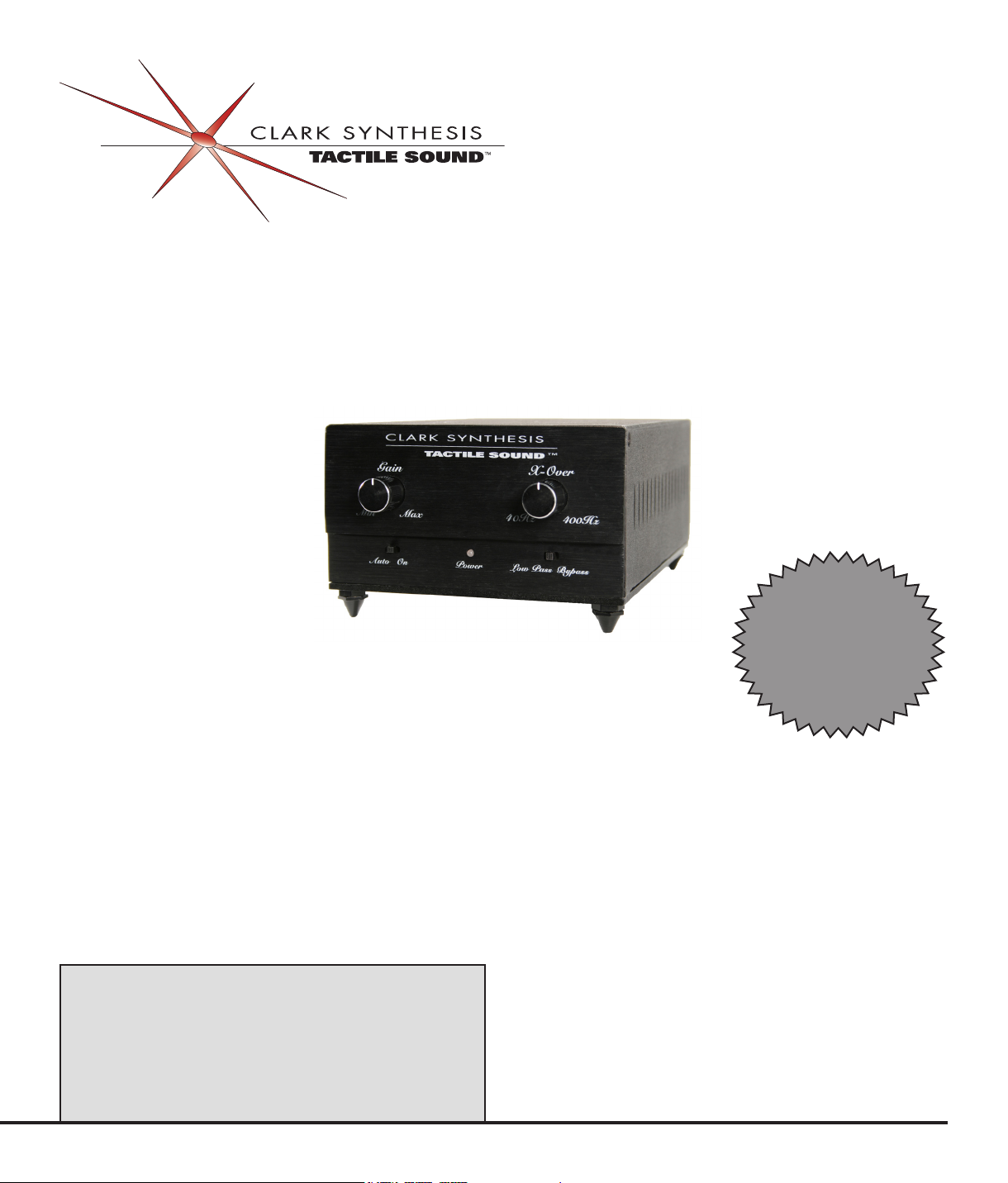
Owner’s Manual
TA1501C Clark Synthesis Amplifier
Table of Contents
PROFESSIONAL
INSTALLERS:
QUICK SETUP
INSTRUCTIONS
ON PAGE 13!
NOTE: READ THIS MANUAL BEFORE
OPERATING THE AMPLIFIER. FAILURE
TO FOLLOW THE INSTRUCTIONS IN THIS
MANUAL MAY RESULT IN DAMAGE TO THE
AMPLIFIER AND/OR THE SOUND EQUIPMENT
BEING POWERED BY THE AMPLIFIER.
Company Overview
Warranty
Safety Instructions
Product Introduction
Unpacking Your Amplier
Product Overview
Setting Up Your Amplier
Operating Your Amplier
Specications
Troubleshooting
Glossary of Terms
Index
Contact Information
2
3
4
5
6
7
13
20
22
23
24
26
28
Page 2
www.clarksynthesis.com
TA1501C Amplier
2
COMPANY OVERVIEW
Thank you for purchasing a Clark Synthesis Tactile Sound Amplier! We are condent this product will be a
welcome addition to your audio system.
For many years, Clark Synthesis has been providing Tactile Sound Transducers for use in home theaters,
listening rooms, outdoor decks, military simulators, theme park attractions, game chairs, professional music,
and swimming pools. With such a variety of products, it is likely that Clark Synthesis has the right type of
transducer for your application.
Because Clark Synthesis transducers require amplication to operate properly, we offer the TA1501C
amplier. The TA1501C is designed for a wide variety of uses, including home theater, professional music,
and outdoor living applications.
With a focus on providing complementary products that provide quality sound and professional-grade
performance, Clark Synthesis is committed to designing products that will take your audio experience to
the next level. We are glad you chose a Clark Synthesis TA1501C amplier and we hope that you will enjoy
many years of listening enjoyment using our products.
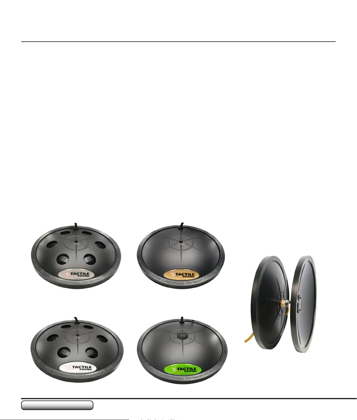
The Clark Synthesis products shown below can be powered with the TA1501C Amplier.
TST429 Platinum Transducer TST329 Gold Transducer
TST239 Silver Transducer
AW339 All-Weather Transducer
AQ339 Aquasonic
Underwater Speaker
Page 3

TA1501C Amplier
3
www.clarksynthesis.com
WARRANTY
United States Warranty and Return Policy
TA1501C CLARK SYNTHESIS AMPLIFIER WARRANTY
Clark Synthesis, Inc. warranties the TA1501C Amplifer to be free from defects and workmanship under normal use for a period of two (2) years from
date of original purchase.
Should warranty service be necessary, Clark Synthesis, Inc. will (at its discretion) repair or replace the defective merchandise with equivalent
merchandise at no charge.
This warranty is valid for the original purchaser and is not extended to subsequent owners. Any applicable implied warranties are limited in duration to
a period of the express warranty as provided herein beginning with the date of the original purchase at retail, and no warranties, whether expressed or
implied, shall apply to this product thereafter. Some states do not allow limitations on implied warranties; therefore these exclusions may not apply to
you. This warranty gives you specic legal rights; however, you may have other rights that vary from state to state.
WHAT IS NOT COVERED
This warranty is valid only if the product is used for the purpose for which it was designed. It does not cover the following:
Damage caused by excessive heat•
Damage through negligence, misuse, accident, or abuse•
Damage caused by incorrectly connecting the amplier to an output device or an electrical source•
Freight damage•
Items repaired by an unauthorized repair facility•
Items purchased from unauthorized individuals or dealers•
Cost of shipping product to Clark Synthesis, Inc.•
Return shipping on non-defective items•
RETURN POLICY
New, unused items purchased from us may be returned within 7 days of the purchase date. Please note: Clark Synthesis will only accept returns
for items that are received in their original packaging, in undamaged and re-sellable (new) condition. Manuals, accessories, warranty cards, and
everything else that came with the unit must be included as well. If your return does not meet these conditions, you will be charged a 15% restocking
fee or have the merchandise returned to you at your expense. Non-defective merchandise can also be returned for a 15% restocking fee. Shipping
charges for all non-defective returns or exchanges are not refundable.
WHAT TO DO IF YOU NEED WARRANTY OR SERVICE
If it becomes necessary for you to return defective merchandise, call Clark Synthesis Customer Service at (800) 898-1945 and you will be given a
Return Authorization Number. Follow the instructions provided by our customer service staff, use suitable packing materials (preferably the original
shipping boxes), and make sure to write your Return Authorization Number on the outside of your box when sending your return to us. Orders that are
returned without an Return Authorization Number may be refused by our returns department! Remember to include a dated proof of purchase from
an authorized dealer. Return freight must be prepaid by the customer: items received freight collect will be refused. If the returned product is found to
contain a manufacturing defect not caused by the customer and a replacement product is sent to the customer, Clark Synthesis, Inc. will pay to ship
the replacement product to a domestic location (within the USA) via ground shipping methods. Costs associated with a) shipping replacement products
intended to replace defective merchandise not caused by a manufacturing defect, b) replacement products shipped outside the USA, or c) replacement
products shipped via shipping methods other than ground shipping will be paid for by the customer.
Make sure the following is included in your package:
• Product to be returned (repacked in original shipping containers)
• Return Authorization Number printed on the outside of the box
• Copy of original invoice with Return Authorization Number printed on it
Return to our Service Department:
RA#: _______________
Clark Synthesis, Inc.
8020 Southpark Circle, Suite 600
Littleton, Colorado 80120
INTERNATIONAL WARRANTY
Contact your International Clark Synthesis dealer or distributor concerning specic procedures for your country’s warranty policies.
Page 4
www.clarksynthesis.com
TA1501C Amplier
4
!
READ THESE INSTRUCTIONS.1.
KEEP THESE INSTRUCTIONS FOR FUTURE REFERENCE.2.
HEED ALL WARNINGS.3.
FOLLOW ALL INSTRUCTIONS.4.
DO NOT USE THIS AMPLIFIER NEAR WATER.5.
CLEAN ONLY WITH A DRY CLOTH.6.
DO NOT BLOCK ANY VENTILATION OPENINGS. INSTALL IN ACCORDANCE WITH THE 7.
MANUFACTURER’S INSTRUCTIONS.
DO NOT INSTALL NEAR HEAT SOURCES SUCH AS RADIATORS, HEAT REGISTERS, STOVES, OR 8.
OTHER EQUIPMENT.
DO NOT DEFEAT THE SAFETY PURPOSE OF THE POLARIZED OR GROUNDING TYPE PLUG- 9. A
polarized plug has two blades, with one wider than the other. A grounding type plug has two blades and a third
grounding prong. The wide blade or the third prong is provided for your safety. If the provided plug does not t into
your outlet, consult an electrician for replacement of the obsolete outlet.
PROTECT THE POWER CORD FROM BEING WALKED ON OR PINCHED, PARTICULARLY AT THE 10.
POINTS NEAREST THE OUTLET AND WHERE THE CORD ENTERS THE AMPLIFIER.
ONLY USE ATTACHMENTS OR ACCESSORIES SPECIFIED BY THE MANUFACTURER.11.
USE ONLY WITH A CART, STAND, TRIPOD, BRACKET, OR TABLE SPECIFIED BY THE 12.
MANUFACTURER OR SOLD WITH THE AMPLIFIER. When a cart is used, use caution when moving the cart
to avoid damaging the amplier.
UNPLUG THE AMPLIFIER DURING LIGHTNING STORMS OR WHEN UNUSED FOR LONG 13.
PERIODS OF TIME.
REFER ALL SERVICING TO QUALIFIED PERSONNEL. 14. Servicing is required when the amplier has been
damaged in any way, such as the power supply cord has been damaged, liquid has been spilled/objects have fallen
into the amplier, the amplier has been exposed to rain or moisture, the amplier does not operate normally, or the
amplier has been dropped.
WARNING: TO REDUCE THE RISK OF FIRE OR ELECTRICAL SHOCK, DO NOT EXPOSE 15.
THIS AMPLIFIER TO RAIN OR MOISTURE.
DO NOT EXPOSE TO DRIPPING OR SPLASHING. DO NOT PLACE OBJECTS FILLED WITH 16.
LIQUID, SUCH AS VASES, ON THIS AMPLIFIER.
TO PREVENT ELECTRIC SHOCK, DO NOT REMOVE TOP OR BOTTOM COVERS. NO USER 17.
SERVICABLE PARTS INSIDE. REFER SERVICING TO QUALIFIED SERVICE PERSONNEL.
TO COMPLETELY DISCONNECT THIS EQUIPMENT FROM THE AC MAINS, DISCONNECT THE 18.
POWER SUPPLY CORD PLUG FROM THE AC RECEPTACLE. THE MAINS PLUG OF THE POWER
SUPPLY CORD SHALL REMAIN READILY OPERABLE.
THE EXCLAMATION POINT WITHIN THE EQUILATERAL TRIANGLE IS INTENDED 19.
TO ALERT THE USER TO THE PRESENCE OF IMPORTANT OPERATING AND
MAINTENANCE INSTRUCTIONS.
THE LIGHTNING BOLT TRIANGLE IS INTENDED TO ALERT THE USER TO THE RISK 20.
OF ELECTRIC SHOCK.
SPECIAL SAFTEY CONSIDERATION FOR THE AQUASONIC SWIMMING POOL 21.
SPEAKER: WHEN USING THE TA1501C AMPLIFIER WITH THE CLARK SYNTHESIS AQUASONIC
SWIMMING POOL SPEAKER, WE RECOMMEND THE FOLLOWING:
- The amplier must be plugged into a GFI-protected outlet.
- Use an isolation transformer. Contact Clark Synthesis for more information.
SAFETY INSTRUCTIONS
!
Page 5

TA1501C Amplier
5
www.clarksynthesis.com
PRODUCT INTRODUCTION
OVERVIEW OF THE AMPLIFIER
The TA1501C amplier is the rst audio amplier designed exclusively for use with Clark Synthesis
transducers. This amplier incorporates the latest digital technology and provides features not available on
many ampliers. Please read this manual in its entirety so you can get the maximum enjoyment from your
Clark Synthesis product(s).
USING THIS AMPLIFIER WITH A CLARK SYNTHESIS TRANSDUCER
The TA1501C amplier works with all Clark Synthesis transducers. This manual outlines how to use this
amplier with our transducers.
CAUTION: This amplier is designed to provide power to one (1) transducer.
!
Please note, the TA1501C can provide more continuous power than the transducer can handle. Why do we
do this? Special effects audio signals often contain peaks that require extra power to be delivered to the
transducer. This amplier will supply those peaks without damaging the transducer, providing you, the user,
with a true Tactile Sound experience.
FEATURES
The Clark Synthesis TA1501C Amplier has the following features:
Class D design for powerful, clean sound•
All-metal cabinet•
Crisp, clean, and compact body design•
Built-in Crossover Control that enables control of the cutoff point from • 40 Hz to 400 Hz
Bypass control that disables the Crossover Control, allowing the amplier to reproduce full-frequency audio•
Front LED that indicates the amplier is connected to AC power•
• Auto/On saves power by turning the amplier stage on only when an audio signal is present
Powered • loop-through allows you to connect multiple ampliers together to a single audio source
Stereo inputs allow you to connect the amplier to multiple sources. The audio is automatically combined •
inside the amplier.
IEC-601 • Connector allows you to use a power cord other than the power cord supplied. This is especially
helpful if you live in a country that requires a different AC plug.
Amplier automatically runs on AC power from 100 to 240 VAC, 50/60 Hz•
The audio input section works with high-level and low-level line signals. This feature permits the amplier •
to work with studio-level and consumer-level audio signals
• 5-way binding posts for connecting the transducer wires
Page 6
www.clarksynthesis.com
TA1501C Amplier
6
UNPACKING YOUR AMPLIFIER
PACKAGE CONTENTS
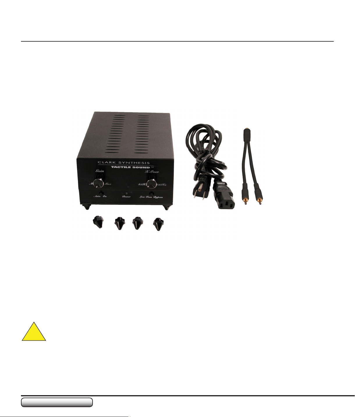
Please remove the amplier and accessories from the carton. You should have the following:
(1) TA1501C Amplier•
(1) AC Power Cord•
(4) Amplier • Feet
(1) • Y Adapter Cable (Color may vary from the image shown here)
(1) Operating Manual•
CONTACT INFORMATION IF PARTS ARE MISSING
If you are missing any items, please contact Clark Synthesis at 1-800-898-1945.
We recommend that you save the original carton to use if you ever have to ship the amplier.
WARNING: Before you set up this amplier, make sure you read and observe the Important Safety
Instructions in this manual.
!
Page 7
TA1501C Amplier
7
www.clarksynthesis.com
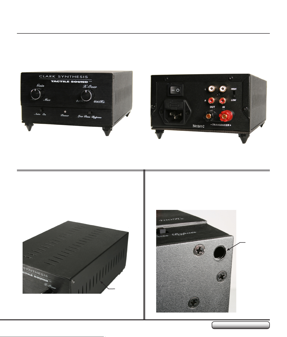
PRODUCT OVERVIEW
Front Panel
Rear Panel
Ventilation Threaded Foot Hole
Vents
Threaded
Foot Hole
Page 8
www.clarksynthesis.com
TA1501C Amplier
8
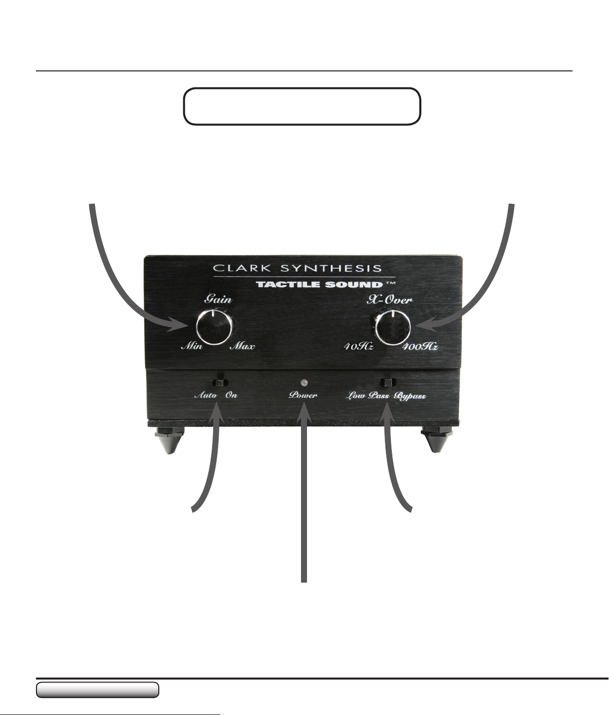
PRODUCT OVERVIEW
Front Panel Overview
Gain (Volume) Control
Crossover (X-Over) Control
Auto/On Switch
Low Pass/Bypass
Switch
Power Indicator Light
Page 9
TA1501C Amplier
9
www.clarksynthesis.com
PRODUCT OVERVIEW
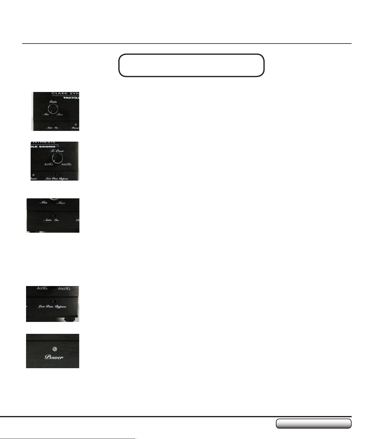
Front Panel Overview
GAIN (VOLUME) CONTROL
The Gain (Volume) Control on the face of the TA1501C amplier controls the degree to which the
input signal is amplied. The gain level, combined with the level of the input signal, determines
the actual volume output.
CROSSOVER (X-OVER) CONTROL
The Crossover Control on the face of the TA1501C amplier controls the range of low-frequency
(bass) sound sent to the output device, i.e. transducer, speaker, etc. This control is only
functional when the Low Pass/Bypass Switch is in the “Low Pass” position. The range of lowfrequency sound controlled by this dial is 40 Hz to 400 Hz.
AUTO/ON SWITCH
The Auto/On Switch allows the user to place the amplier into either Auto On/Standby mode or
On.
When the switch is set to “Auto” and no input signal is received by the amplier, the amplier
stage will power down and go into Standby mode. Upon sensing an input signal, the amplier will
power on automatically.
When the switch is set to “On,” the amplier will remain powered on, regardless of whether an
input signal is present or not.
LOW PASS/BYPASS SWITCH
The Low Pass/Bypass Switch enables and disables the Crossover function and control dial
of the amplier. When the switch is in the “Low Pass” position, the amplier only passes lowfrequency sounds. When the switch is in the “Bypass” position, the amplier passes the full
range of audio frequencies.
POWER INDICATOR (LED)
The Power Indicator LED displays the power mode. If the LED is:
RED- The amplier is plugged into AC power and the power switch on the back of the •
amplier is switched to “On.” If the Auto/On switch is set to “Auto,” a red LED indicates no
audio input signal has been received by the amplier.
GREEN- The amplier is plugged into AC power and the power switch on the back of the •
amplier is switched to “On.” If the Auto/On switch is set to “Auto,” a green LED indicates an
audio input signal is being received by the amplier, or, if the Auto/On switch is set to “On,”
the amplier is on.
Page 10
www.clarksynthesis.com
TA1501C Amplier
10
PRODUCT OVERVIEW
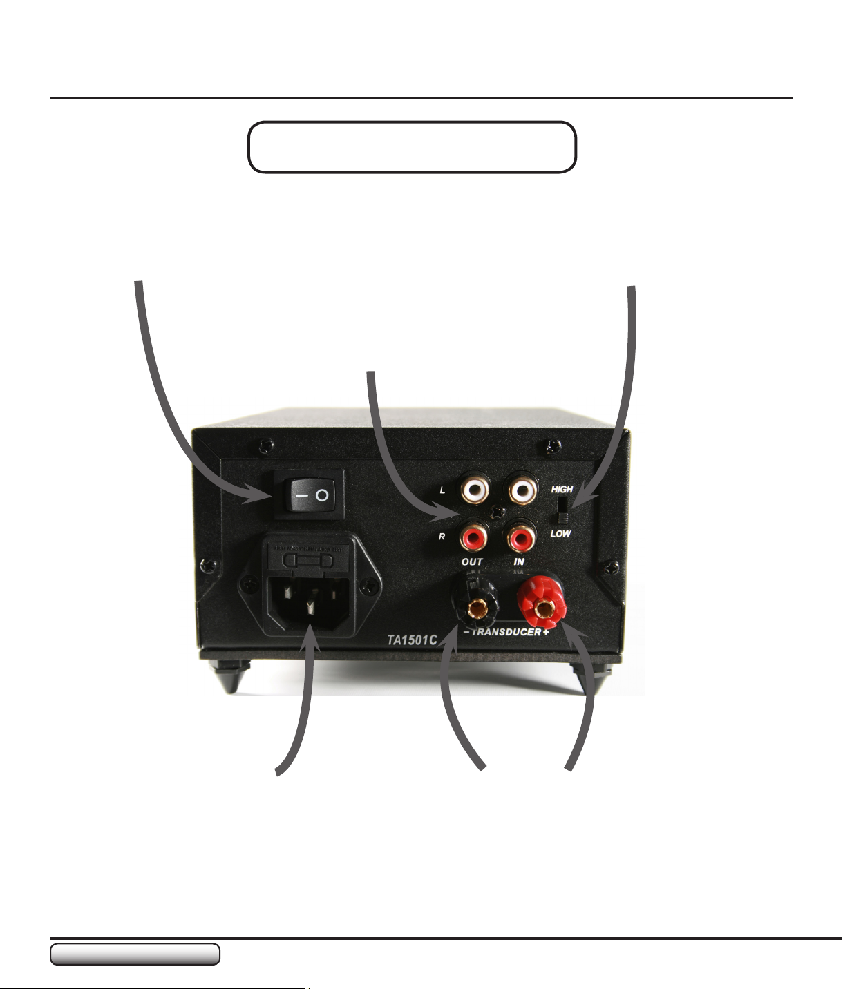
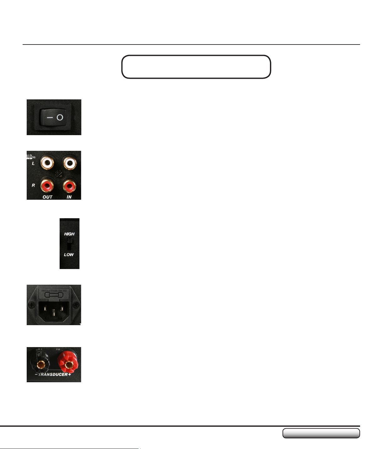
Rear Panel Overview
AC Power Switch
Audio Input/Output Connectors
High/Low Input Signal Switch
AC Power Cord Connector
(IEC-601)
Transducer
Connector
Page 11
TA1501C Amplier
11
www.clarksynthesis.com
PRODUCT OVERVIEW
Rear Panel Overview
AC POWER SWITCH
The AC Power Switch controls the AC power to the amplier. The round circle on the switch
represents “OFF” and the line represents “ON.” This switch works independently from the Auto/
On Switch, which is discussed in the Front Panel Overview section.
AUDIO INPUT/OUTPUT CONNECTORS
The Audio Input/Output Connectors accept standard RCA plugs. These connectors are split into
Left and Right channels, as indicated by L and R on the panel. The Left and Right sides each
have one Audio Out and one Audio IN.
HIGH/LOW INPUT SIGNAL SWITCH
The High/Low Switch allows the user to select the voltage level of the audio input source. For
example, if the input source is a standard home theater or stereo receiver, the switch should be
set to “High.” If the input source is an MP3 player or portable CD player, the switch should be
set to “Low.” For any other type of input source, begin by using the “High” setting. If you are not
receiving enough output, try the “Low” setting.
AC POWER CORD CONNECTOR (IEC-601)
The AC Power Cord Connector is an adaptable connector that allows users to connect
IEC-601 compatible AC cords to the amplier. This type of connector is especially benecial
for international compatibility. The connector also houses a fuse used to protect the unit from
surges.
TRANSDUCER CONNECTOR
The Transducer Connector is used to connect the transducer to the amplier. This connector
uses 5-way binding posts, which allow for a variety of ways to connect the transducer wire (see
“Connecting the Transducer to the Amplier” on page 18).
Page 12

www.clarksynthesis.com
TA1501C Amplier
12
SETTING UP YOUR AMPLIFIER
This page intentionally left blank
Page 13

TA1501C Amplier
13
www.clarksynthesis.com
SETTING UP YOUR AMPLIFIER
Quick Setup Instructions
The following instructions are a quick overview of the steps necessary to install your new
amplier. For more detailed instructions, please refer to the sections in the manual that are
referenced below.
Remove the amplier from its package (for package contents, see “Unpacking Your 1.
Amplier” on page 6).
Insure you have set the amplier to the following settings: 2.
• AC Power Switch is set to “Off”
• Gain (Volume) Control is set to “Min”
• High/Low Input Signal Switch is set to “High”
For more detail on these settings, including pictures, see “Initial Settings Prior to
Making Connections” on page 14.
Install the amplier 3. feet if you are installing on a at surface. Do not install the feet if
you are installing in a Clamping Rackshelf (see “Placing/Mounting the Amplier” and
“Mounting the Amplier(s) on a Clamping Rackshelf” on pages 14-15).
Connect the audio input source to the amplier. Insure you are connecting to both the 4.
Left and Right Input Connectors (see “Connecting the Audio Source” on page 16).
Connect the transducer to the amplier (see “Connecting the Transducer to the 5.
Amplier” on page 18).
If you using multiple TA1501C ampliers to run multiple transducers, connect the loop-6.
through connections using RCA cables (see “Using the Powered Loop-Through to Run
Multiple Transducers” on page 19).
Plug the AC Power Cord into an electrical outlet.7.
Once connected, turn your system on and 8. balance the sound (see “Balancing the
Transducer with the Subwoofer” on page 20).
Your system is now ready for use.9.
Page 14
www.clarksynthesis.com
TA1501C Amplier
14
SETTING UP YOUR AMPLIFIER
Initial Settings Prior to Making Connections
CAUTION: Before connecting any wires or input/output lines, insure all equipment is
off and no signals are being sent from the input device.
!
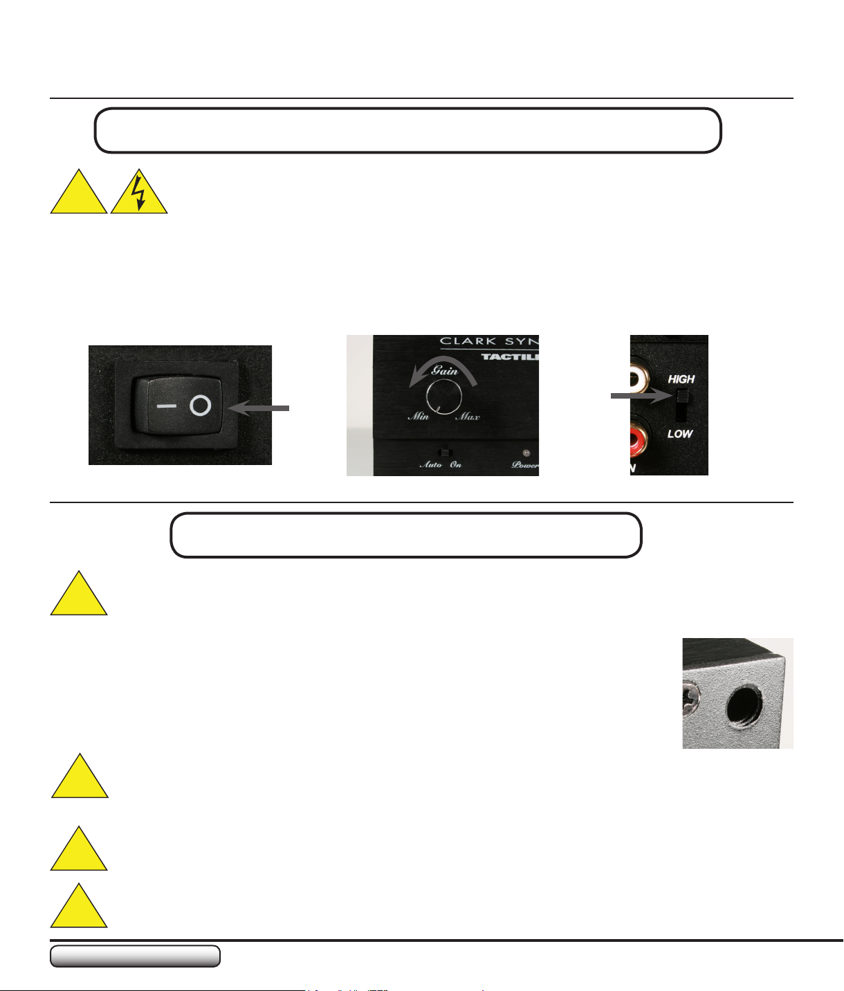
In order to reduce the chances of accidentally damaging the amplier or transducer, please set the
amplier controls to the safety positions described and shown below:
Set the • AC Power Switch on the back of the amplier to the “Off” position (see photo #1)
Set the • Gain (Volume) Control to “Min” (completely counter-clockwise, see photo #2)
Set the • Input Signal Switch on the back of the amplier to the “High” position (see photo #3)
Photo #1
Placing/Mounting the Amplier
If you are placing the amplier on a at surface (not including mounting the amplier on a
Clamping Rackshelf), you must install the feet supplied with the amplier. Installing these feet will
!
help provide sufcient cooling to the bottom plate of the amplier.
To install the feet, follow the steps listed below:
Gently place the amplier on a non-abrasive surface with the bottom of the amplier •
facing up.
Hand thread one of the feet into a receiving hole, insuring the threads do not crossthread.•
When properly threaded, tighten the foot by hand until it is snug.•
CAUTION: Do not overtighten the feet. The bottom plate of the amplier is made of soft metal
!
and the threads can easily be stripped if the feet are improperly threaded or overtightened.
CAUTION: The bottom of the amplier can get hot. Do not place anything directly under the
amplier that is ammable or can be damaged by heat. Failure to install the feet may result in
!
damage to the amplier and/or the surface upon which it is sitting (not including a Rackshelf).
Photo #2
Photo #3
CAUTION: Insure there are two (2) inches of clearance around the sides and top of the amplier.
!
DO NOT block the top or side air vents.
Page 15
TA1501C Amplier
15
www.clarksynthesis.com
SETTING UP YOUR AMPLIFIER
Mounting the Amplier(s) on a Clamping Rackshelf
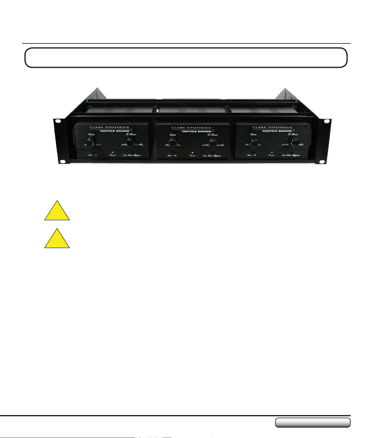
Up to three (3) TA1501C Ampliers may be installed in a 2U rack space using a Clamping Rackshelf.
When mounting in a Clamping Rackshelf, DO NOT install the feet provided with the amplier. The
bottom of the amplier MUST be in full contact with the metal rackshelf.
CAUTION: Insure even spacing between the ampliers and the side walls of the shelf. This
will aid in providing adequate ventilation for the amplier(s).
!
CAUTION: To prevent overheating, insure the entire rack has adequate ventilation.
!
Page 16
www.clarksynthesis.com
TA1501C Amplier
16
SETTING UP YOUR AMPLIFIER
Connecting the Audio Source
HOME THEATER
There are several different ways to hook up your system in terms of which source material (signal)
is delivered to the amplier(s) and transducer(s). Since our inception, we have discovered that
approximately half of our customers prefer using the LFE/SUB signal with their transducers. The other
half prefer using the Right Front (RF) and Left Front (LF) signals. Additionally, there are a few people
who like to use multiple signals concurrently. In the following instructions, we provide you with general
diagrams for each of these hookup methods.
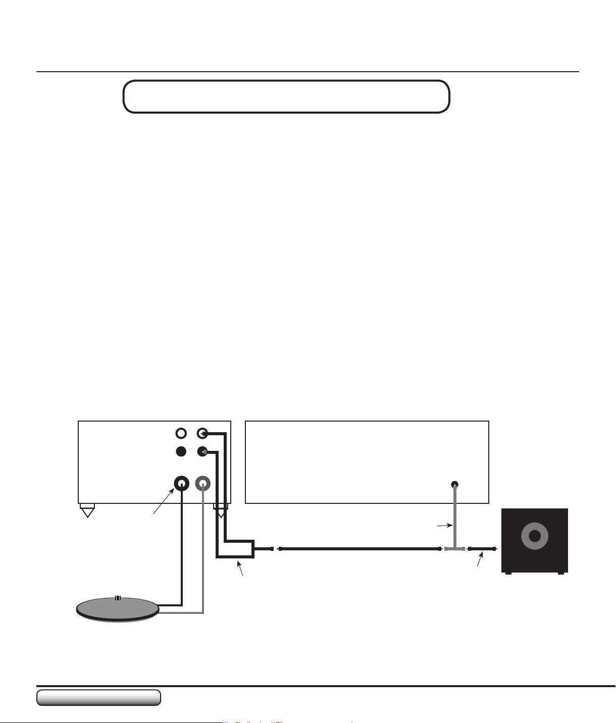
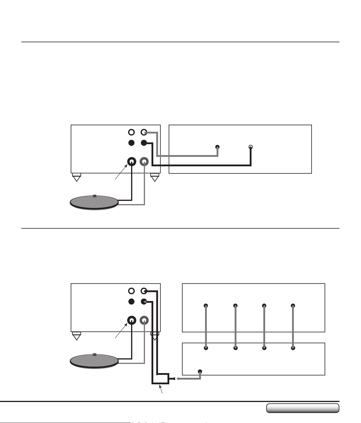
LFE/SUB Hookup
The LFE, SUB, or Subwoofer output is the signal that you send to the subwoofer.
If your receiver has only one LFE/SUB/Subwoofer output port, connect a “Y” adapter to that output.
This will allow you to split the signal between the transducer and the subwoofer. To do this properly,
connect your subwoofer to one side of the “Y” adapter. Connect the TA1501C amplier to the other
side of the “Y” adapter. To reduce the amount of noise produced when using this signal, use another
“Y” adapter cable when connecting to the amplier. This will allow you to connect the signal into both
the Left and Right input connectors on the amplier.
L
R
Transducer Output
Transducer
OUT
Surround-Sound ReceiverTA1501C Amplier
IN
–
+
Y Adapter
Y Adapter
LFE/SUB
Subwoofer
To Input of
Powered
Subwoofer
Page 17
TA1501C Amplier
17
www.clarksynthesis.com
SETTING UP YOUR AMPLIFIER
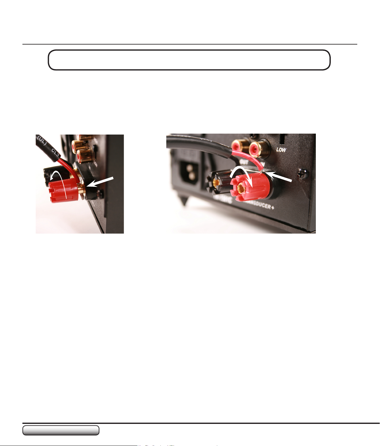
Right Front (RF) and Left Front (LF) Hookup
For this hookup, connect the RF and LF Pre-Amp Outputs to the TA1501C amplier inputs.
NOTE: Not all receivers have Pre-Amp outputs for the Right Front and Left Front outputs. If you
have a question about your receiver’s outputs, please consult your owner’s manual or contact your
receiver’s manufacturer.
TA1501C Amplier
L
R
OUT
IN
–
+
Transducer Output
Transducer
Multiple Signal Hookup
This conguration is a little more complicated. You will need a small mixer to make this work.
Connect the signals you want to use to the mixer input. Then, connect the mixer output to the
TA1501C amplier input using a “Y” adapter.
TA1501C Amplier
L
R
OUT
IN
Surround-Sound Receiver
Pre-Amp Audio Out
LF
Surround-Sound Receiver
Pre-Amp Audio Out
LF CENTER LFE/SUB
RF
RF
Transducer Output
Transducer
–
+
CH4CH3CH2CH1
OUTPUT
Mixer
Y Adapter
Page 18
www.clarksynthesis.com
TA1501C Amplier
18
SETTING UP YOUR AMPLIFIER
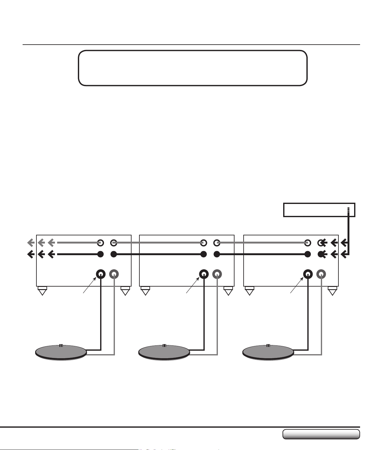
Connecting the Transducer to the Amplier
If you are able to locate the amplier within 3 feet of the transducer (3 ft. is the approximate length of
the speaker wire attached to the transducer), connect the transducer wires directly to the amplier.
This can be done by unscrewing the wire binding posts, inserting the wire through the hole in the post
(see photo #1 on this page), and then retightening the binding posts (see photo #2). To insure you
have a secure connection, make sure the insulation on the wire does not get pinched when tightening
the cap on the binding post.
Photo #2Photo #1
NOTE: The 5-Way binding posts can be connected to in several ways. You can insert banana plugs
into the end of the posts, insert pin connectors or bare wire through the hole in the post (as shown in
photo #1), wrap bare wire around the posts and tighten the post caps, or install lug terminals around
the posts.
If you are unable to locate the amplier within 3 feet of the transducer, you will need to splice the
speaker wire coming out of the transducer with another comparable wire of the correct length. Once
spliced, attach the ends of the added wire to the amplier as discussed above.
NOTE: Our general wire size recommendations for additional wire are as follows:
0 to 25 feet, 16 AWG
25 to 50 feet, 14 AWG
50 to 75 feet, 12 AWG
Page 19
TA1501C Amplier
19
www.clarksynthesis.com
SETTING UP YOUR AMPLIFIER
Using the Powered Loop-Through
to Run Multiple Transducers
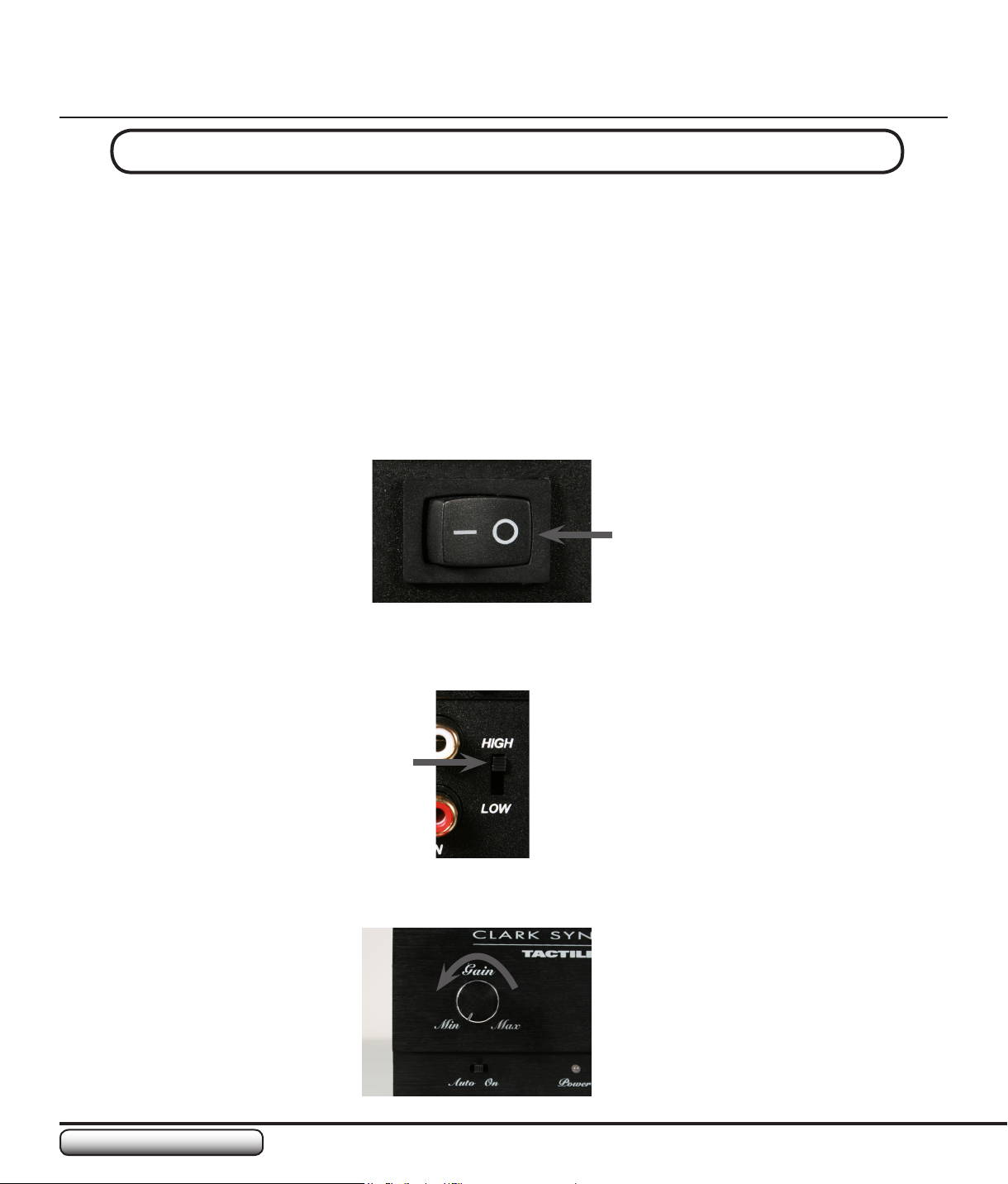
The TA1501C has powered loop-through. This feature enables the user to take the signal from an
audio source and pass it to a series of TA1501C ampliers in order to drive multiple transducers.
The drawing for this type of hookup is shown below. Use a standard “Y” adapter to get the signal from
the audio source (e.g., from the LFE/SUB output). If the input signal is coming from two ports (e.g.,
from the RF and LF outputs), the “Y” adapter is not needed. The wires from those connectors can be
connected directly to the “Audio In” connectors of the TA1501C.
Subsequent wiring between the ampliers can be done with single or paired wire connectors. The
wiring for the transducers is the same as that for a single transducer hookup (see “Connecting the
Transducer to the Amplier” on the previous page).
Audio Source
TA1501C Amplier #1TA1501C Amplier #2TA1501C Amplier #3
LLL
RRR
OUTOUTOUT INININ
–––
+++
Transducer OutputTransducer OutputTransducer Output
Transducer #1Transducer #2Transducer #3
Page 20
www.clarksynthesis.com
TA1501C Amplier
20
OPERATING YOUR AMPLIFIER
Balancing the Transducer with the Subwoofer
Once you have properly set up your amplier, it is important to take time to balance the transducer and
subwoofer sound. The volume of the transducer is controlled by the receiver and will rise or fall in direct
proportion to that of the primary speakers. This proportion is determined by both the volume setting on the
receiver and the gain setting on the TA1501C amplier.
NOTE: Some receivers have internal, automatic balancing systems. These systems rely on microphones
that sense the sound levels within the room. Since tactile sound transducers are heard through your body,
instead of through the air, automatic balancing systems may be ineffective when balancing the subwoofer
volume. We suggest using the following procedure, rather than activating the automatic balancing system.
STEPS:
Set the TA1501C 1. Power Switch on the back of the amplier to “OFF” (see photo #1 below).
Photo #1
If you are using a low-level signal, such as an MP3 player, set the 2. High/Low Switch to “LOW.” If you are
connecting to a high-level signal, such as an A/V receiver, set the switch to “HIGH.” (see photo #2).
Photo #2
Turn the 3. Gain Control counter-clockwise to the “MIN” position (see photo #3).
Photo #3
Page 21
TA1501C Amplier
21
www.clarksynthesis.com
OPERATING YOUR AMPLIFIER
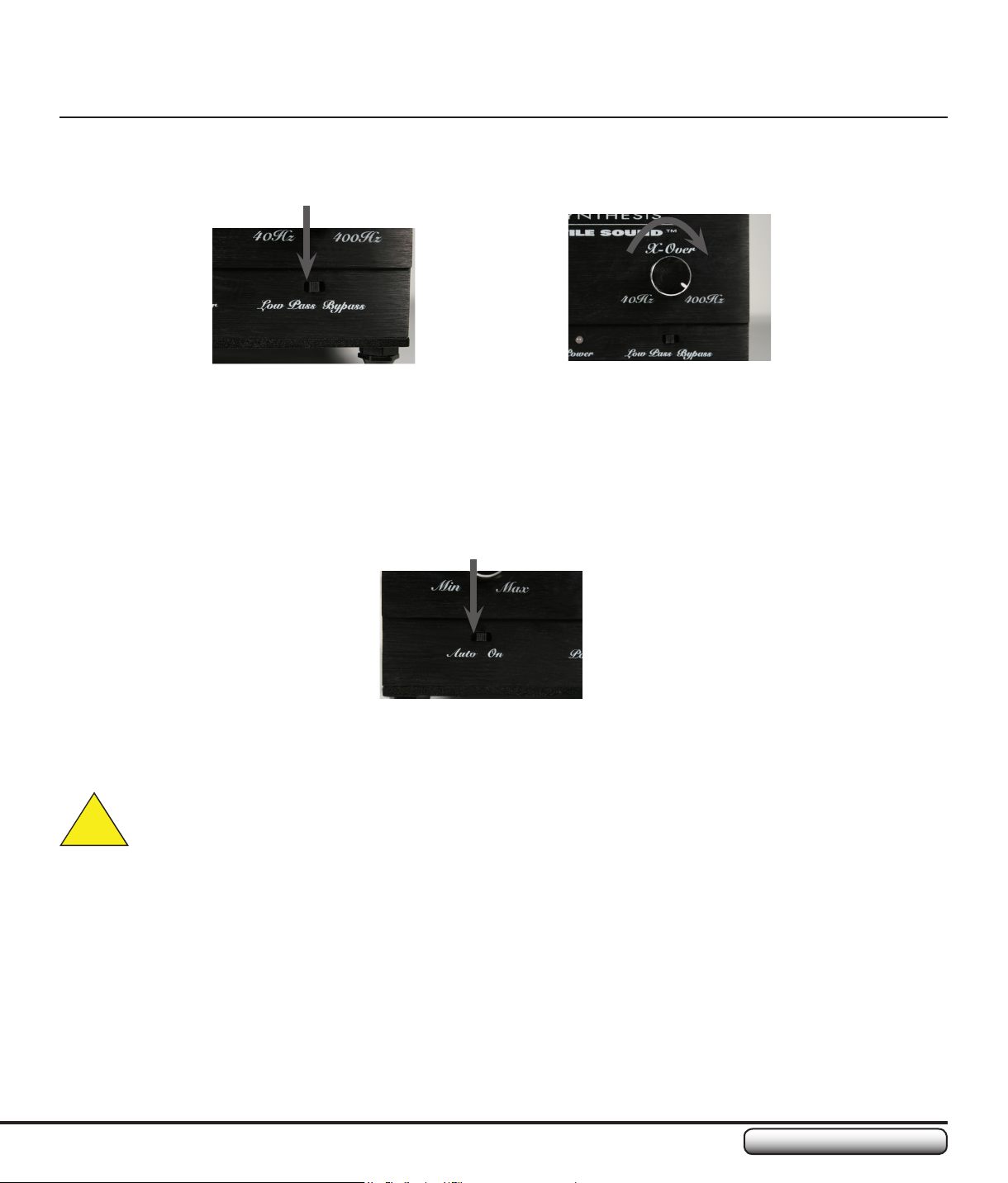
If you are using the LFE/SUB signal as your input for the transducer, insure the 4. Low Pass/Bypass Switch
is set to “Low Pass” (see photo #4) and the Crossover Control on the TA1501C is set to 400 Hz (photo #5).
If you are using the RF/LF signal, set the switch to “Bypass.”
Photo #4
Select an action-based DVD and play your favorite action scene.5.
While the scene is playing, set your home theater speakers to a level equivalent to the maximum level 6.
where you would listen to them.
Stop the action scene from playing, leaving the volume setting at the level you just determined.7.
Turn the subwoofer volume on the powered subwoofer(s) all the way down.8.
Turn on the TA1501C AC 9. Power Switch on the back of the amplier.
Set the TA1501C 10. Auto/On Switch to “Auto” (see photo #6).
Photo #6
Playing your favorite action scene again, turn up the 11. Gain Control until you feel the action playing through
the transducer.
CAUTION: If you hear distortion from the transducer, immediately reduce the Gain level.
Photo #5
!
NOTE: If the TA1501C amplier is located some distance from the furniture, it may be helpful to have
someone else adjust the volume.
With the scene still playing, increase the subwoofer volume on the powered subwoofer(s) until the low 12.
frequency sound is balanced.
Finally, if using the LFE/SUB signal as the input for the transducer and you have selected the “Low Pass” 13.
setting, adjust the TA1501C Crossover and Gain Controls until the experience is at its peak.
NOTE: Some people are uncomfortable hearing dialogue through their bodies. Use the Crossover Control
to remove the dialogue from the audio signal by adjusting the Hz range reproduced by the amplier. This is
only possible if the amplier is set to “Low Pass,” which activates the Crossover Control.
Page 22
www.clarksynthesis.com
TA1501C Amplier
22
SPECIFICATIONS
General
Power Supply................................................................................................................100 – 240 VAC, 50/60 Hz, Auto•
Standby Current (110 VAC / 220 VAC)....................................................................................................0.12 A / 0.11 A•
Max Current (110 VAC / 220 VAC)..............................................................................................................2.4 A / 1.1 A•
Total Amplier Efciency..........................................................................................................................................70%•
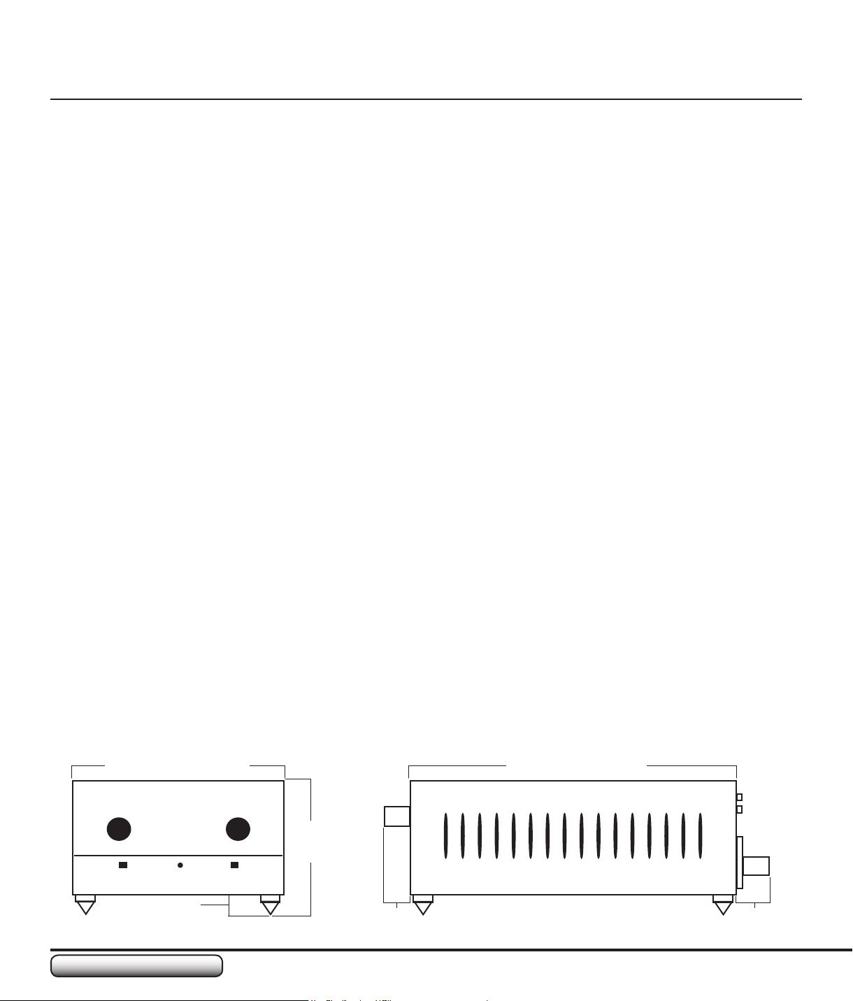
• Dimensions, without Feet (W x H x D).......................5.125 in x 2.75 in x 8.875 in (130.2 mm x 69.9 mm x 225.4 mm)
Dimensions, with • Feet (W x H x D)............................5.125 in x 3.25 in x 8.875 in (130.2 mm x 82.6 mm x 225.4 mm)
Weight................................................................................................................................................3.5 lbs. (1.588 kg)•
Fuse..............................................................................................................................................................T3AL 250V•
Input Section
Input Impedance...................................................................................................................................................16 kΩ•
Input Sensitivity (1 W, Input switch set to Low)...................................................................................................30 mV•
Input Sensitivity (1 W, Input switch set to High)................................................................................................100 mV•
Input Sensitivity (150 W, Input switch set to Low).............................................................................................360 mV•
Input Sensitivity (150 W, Input switch set to High)...................................................................................................1 V•
Loop Through Amplication.......................................................................................................................................x 1•
Auto-On..............................................................................................................................................Switch Selectable•
Crossover Section
• Crossover Frequency Selection.............................................................................................................40 Hz – 400 Hz
Crossover Frequency Selection (+ 0 dB, -3 dB)....................................................................................35 Hz – 420 Hz•
Amplier Section
• Output Power....................................................................................................................150 Watts RMS into 4 Ohms
Total Harmonic Distortion (at 1 Watt into 4Ω).......................................................................................................0.15%•
Total Harmonic Distortion (at 150 Watts into 4Ω).................................................................................................0.08%•
• Frequency Response..............................................................................................................................5 Hz to 36 kHz
Frequency Response (+0 dB, -3 dB)....................................................................................................28 Hz to 36 kHz•
5.125 in (130.2 mm) 7.375 in (187.3 mm)
3.25 in
(82.6 mm)
.5 in
(12.7 mm)
.625 in
(15.9 mm)
.875 in
(22.2 mm)
Page 23

TA1501C Amplier
23
www.clarksynthesis.com
TROUBLESHOOTING
Symptom Troubleshooting Question Remedy
No Power Is the power cord plugged into the wall? Plug the power cord into the wall.
Is the power cord plugged into the back of
the amplier?
Is the power switch on the back of the
amplier switched on?
Is the fuse blown? Replace the fuse with a fuse of the same
No Sound Is the transducer connected? Connect the transducer properly.
Is the input source connected to the
amplier input?
Is the source outputting a signal? Connect the source to another amplier
Is the Gain (Volume) Control turned up? Slowly turn up the Gain (Volume) Control.
Is the input signal from the source too
weak to turn on the amplier?
Did the transducer stop working? Turn the Gain Control down, wait a few
Plug the power cord into the back of the
amplier.
Switch on the power switch.
rating.
Connect the input source.
to verify the source is working.
Set the Auto/On Switch to “On.” If sound
is produced, set the switch back to “Auto”
and either increase the source volume or
set the input switch to “LOW.” Depending
on the source, it is possible you may have
to do both.
minutes, then try again.
Not Enough Sound Is the Gain (Volume) Control adjusted
properly?
Sound Comes and Goes Is the input signal from the source too
weak to turn on the amplier?
Did the transducer stop working? Turn the Gain Control down, wait a few
Output Contains Highfrequency Material
NOTE: This assumes
you DO NOT want highfrequency material.
Output Does Not Contain
High-frequency Material
NOTE: This assumes you
DO want high-frequency
material.
Is the amplier set to Low Pass only? Set the Low Pass/Bypass Switch to “Low
Is the Crossover set correctly? (If using
the Low Pass setting)
Is the LFE/SUB signal connected to the
amplier input?
Is the amplier set to Bypass mode? Set the Low Pass/Bypass Switch to
Is the Crossover set correctly? (If using
the Low Pass setting)
Is a full-frequency signal connected to the
amplier input?
Turn up the source volume and the Gain
(Volume) Control or set the input switch to
“LOW.” You may need to do both.
See remedy for the same troubleshooting
question in “No Sound Output” (above).
minutes, then try again.
Pass.”
Turn the Crossover Control counterclockwise to eliminate high frequency
material.
Connect the home theater receiver’s LFE/
SUB signal to the amplier’s input.
“Bypass.”
Turn the Crossover Control clockwise to
include more high-frequency material.
Connect the home theater receiver’s RF
and LF signals to the amplier’s input.
Page 24

www.clarksynthesis.com
TA1501C Amplier
24
GLOSSARY OF TERMS
Term Denition
2U Rack Space With U (Unit), being a standard unit of measurement for audio/video racking
systems, a 2U rack is a standard rack that occupies 2 units within the rack
system. A 2U rack is 3.5 inches (88.9 mm) high.
Audio Input/Output Connectors Audio connectors on the amplier that receive or transmit the main signal.
Auto/On Switch The switch under the Gain Control that allows the user to place the amplier
into either Auto On/Standby mode or On.
When the switch is set to “Auto” and no input signal is received by the
amplier, the amplier will go into Standby mode. Upon sensing an input
signal, the amplier will power on automatically.
When the switch is set to “On,” the amplier will remain powered on,
regardless of whether an input signal is present or not.
Automatic Balancing System Included in some Home Theater Surround-Sound Receivers, this feature
uses microphones to measure room sound levels in order to properly
balance low, mid, and high level sound output from the receiver.
AWG Abbreviation for American Wire Gauge. Commonly used to designate wire
size. The smaller the AWG number, the larger the wire size.
Crossover (X-Over) Control The control on the face of the TA1501C amplier that controls the range
of low-frequency (bass) sound sent to the output device, i.e. transducer,
speaker, etc. This dial is only functional when the Low Pass/Bypass Switch
under the control is set to “Low Pass.” The range of low-frequency sound
that is controlled by this dial is 40 Hz to 400 Hz.
Gain Control The control on the face of the TA1501C amplier that controls the degree to
which the input signal is amplied. The gain level, combined with the level of
the input signal, determines the actual volume output.
High/Low Input Signal Switch A switch on the TA1501C that allows the user to use 1 V RMS or 316 mV
RMS inputs. Examples include a home theater receiver (“High” Level) vs. an
MP3 player (“Low” Level).
IEC-601 Connector An adaptable AC connector that allows users to connect IEC-601 compatible
AC cords to the amplier. This type of connector is especially benecial for
international compatibility.
Page 25

TA1501C Amplier
25
www.clarksynthesis.com
GLOSSARY OF TERMS
Term Denition
LFE/SUB Signal A low-frequency signal that is often associated with subwoofer (bass) sound.
Loop-through The ability to connect multiple amplifers to a single audio source.
Low Pass/Bypass Switch A switch on the TA1501C that enables and disables the Crossover function
of the amplier.
Multiple Signal Hookup Using multiple audio input signals, e.g., RF, LF, Center, and LFE/SUB
signals, as the source signal for the amplier. This type of hookup requires a
mixer.
Pre-Amp A low-voltage, internal amplier within audio receivers that prepares the
signal to be sent to a powered amplier.
Receiver As used in this manual, a receiver is a general term for the audio source. An
example would be a Home Theater Surround Sound Receiver.
RF/LF Signals Right Front and Left Front signals.
Tactile Sound A term used to describe the effect of hearing sound by making physical
contact with a surface that has been activated with an audio transducer.
Transducer (Audio) An audio device that reproduces sound by physically activating a resonant
surface.
X-Over Control (see denition under Crossover Control)
Y Adapter An adapter cable that takes an audio input signal from a single connector
and splits the signal so it can be sent to two connectors.
Page 26

www.clarksynthesis.com
TA1501C Amplier
26
INDEX
Symbols
5-Way binding post 5, 18
A
AC Power Cord Connector 5, 10, 11
AC Power Switch 10, 11, 13, 14, 20, 21, 23
Audio Input/Output Connectors 10, 11, 13, 16, 17, 19, 24
Auto/On Switch 5, 8, 9, 21, 23, 24
B
Balancing 13, 20
C
Contact Information 6
Crossover Frequency 5, 9, 21, 22, 23
Crossover (X-Over) Control 8, 9, 21, 23, 24
D
Dimensions 22
F
Features 5
Feet 6, 7, 13, 14, 15, 22
Frequency Response 22
Front Panel 7, 8, 9
G
Gain (Volume) Control 8, 9, 13, 14, 20, 21, 23, 24
Glossary 24
H
High/Low Input Signal Switch 10, 11, 13, 14, 20, 23, 24
I
IEC-601 Connector. See AC Power Cord Connector
Impedance 22
L
Left Front (LF) 25
LFE/SUB Hookup 16
Loop-Through 5
Low Pass/Bypass Switch 8, 9, 21, 23, 25
Page 27

TA1501C Amplier
27
www.clarksynthesis.com
M
Mixer 17
Mounting 14
Clamping Rackshelf 14, 15
Multiple Signal Hookup 17
P
Package Contents 6
Placing/Mounting 14
Power Indicator (LED) 8, 9
Power (Output) 22
Pre-Amp 17, 25
Q
Quick Setup Instructions 13
R
Rear Panel 7, 10, 11, 14, 20
Return Policy 3
RF/LF Hookup 17
Right Front (RF) 25
INDEX
S
Specications 22
T
Transducer Connector 10, 11, 18
Troubleshooting 23
W
Warranty 3
International Warranty 3
Wire size 18
Y
Y Adapter 6, 16, 17, 19
Page 28

05/2008 Ver. 1 ©2008 Clark Synthesis, Inc.
For additional questions/concerns/issues, contact Clark Synthesis or visit our web site.
Clark Synthesis, Inc.
8020 Southpark Circle, Suite 600
Littleton, CO 80120
Phone: 1-800-898-1945
Fax: 303-797-7501
Web: www.clarksynthesis.com
Email: [email protected]
www.clarksynthesis.comwww.clarksynthesis.com
 Loading...