


CLARKSON SLURRY KNIFE GATE VALVES - KGA AND KGA+
INSTALLATION AND MAINTENANCE INSTRUCTIONS
Before installation these instructions must be fully read and understood
CLARKSON KGA+
VALVE ASSEMBLIES
KGA+ INDEX
1. General information ...................................... 2
2. Initial inspection ............................................ 2
3. Installation instructions ................................ 3
4. Operation ....................................................... 4
5. Lockouts ........................................................ 6
6. General maintenance.................................... 6
7. Spare parts .................................................... 7
8. Storage ........................................................... 8
9. Sleeve replacement ...................................... 9
10. Secondary seal replacement ...................... 10
11. Disassembly and assembly instructions ... 12
12. Field replacement of gates ......................... 15
13. Installation instructions for splash guard . 16
14. Installation instructions for drainplate ..... 16
15. Lifting ........................................................... 17
16. Manual handwheel actuator assembly ...... 18
17. Bevel gear actuator assembly .................... 18
18. Air cylinder actuator assembly................... 19
19. Hydraulic cylinder actuator assembly ....... 19
KGA INDEX
20. General information .................................... 20
21. Initial inspection .......................................... 20
22. Installation instructions .............................. 21
23. Operation ..................................................... 22
24. Lockouts ...................................................... 24
25. General maintenance.................................. 24
26. Spare parts .................................................. 25
27. Storage ......................................................... 26
28. Sleeve replacement .................................... 27
29. Wiper replacement ...................................... 28
30. Disassembly and assembly instructions ... 28
31. Field replacement of gates ......................... 32
32. Installation instructions for splash guard . 33
33. Lifting ........................................................... 34
34. Manual handwheel actuator assembly ...... 35
35. Bevel gear actuator assembly .................... 35
36. Air cylinder actuator assembly................... 36
37. Hydraulic cylinder actuator assembly ....... 36
This instruction manual provides installation,
operation and maintenance recommendations
for both the Clarkson KGA and Clarkson KGA
Plus (KGA+) slurry knife gate valves. The KGA
was first introduced in the 1970’s and the
KGA+ design was introduced in2010. While
both products are very similar, the KGA+ offers
additional features with resulting differences in
maintenance procedures and parts lists.
The first section covers the KGA+, the second
the KGA. Please refer to the KGA+ or KGA
section for complete instructions.
KGA+ and KGA identified
The KGA+ is easily identified from the KGA by
several prominent features:
Mating flanges: the KGA has slotted mating
flanges to mate with ASME B16.5/150 pipe
flanges in sizes above NPS 8 (DN 200). The
KGA+ features full flange design in all size
and can beadapted to many different flange
drillings.
© 2017 Emerson. All Rights Reserved.Emerson.com/FinalControl VCIOM-06601-EN 19/08
CLARKSON SLURRY KNIFE GATE VALVES - KGA+
INSTALLATION AND MAINTENANCE INSTRUCTIONS
Secondary seal: the KGA utilizes a multipart
gate wiper assembly to wipe the gate and
reduce potential for discharge from the top of
the valve where the gate enters the housing
assembly. The KGA+ features a secondary seal
assembly capable of being lubricated without
disassembly. Similar to what is currently
offered on the KGD; this new seal design
incorporates an external lubrication fitting to
directly inject lubrication into the seal’s interior
(patent pending).
Simplified housing assembly: housing spacers
found on the KGA have been eliminated from
the KGA+ allowing for an easier disassembly /
assembly process.
With these changes, spare parts and
interchangeability with the prior design have
been impacted. These changes are detailed
inSections ‘Spare parts’ (KGA+ and KGA).
1 GENERAL INFORMATION
1. The KGA+ is a packingless, slurry knife
gate valve. All the sealing is accomplished
by the elastomeric sleeves in the valve
housing. The sleeves also form the wear
section for the valve. The gate is removable
for inspection or replacement while the
valveisin service.
2. The KGA+ is BIDIRECTIONAL
(two-way shut-off) product and can be
installed without concern over direction of
flow. Since they will shut-off equally with
in either direction, you will find no arrows
or other indicators of a direction of flow or
seatside.
3. Clarkson slurry knife gate valves are
suitable for on-off service only. They are
notto be used in a throttling application.
4. The style, size, pressure rating and material
selection are the responsibility of the piping
system designer.
5. All valves should be operated within the
design pressure and temperature ranges.
Under no circumstances should the valves
be operated at conditions outside these
parameters. Do not exceed 100% of the
maximum pressure rating of the valve at
anytime during its operation. Pressure
spikes beyond the valve’s pressure rating
are solely the responsibility of the user.
2 INITIAL INSPECTION
1. Examine entire valve and report any
damageor discrepancies immediately.
2. Sleeves: visually examine the sleeves
interior, looking for chunking, irregularities
or other damage. It is not recommended you
remove the retainer flanges (if equipped).
3. Retainer flanges: sizes NPS 8 (DN 200) and
below may or may not have the optional
retainer flanges, retainer flanges are
standard on sizes NPS 10 (DN 250) and
larger. Visually examine the retainer flanges
surfaces, looking for tears, irregularities or
other damage. Check tightness of retainer
flange bolting.
4. Operators: standard manual handwheels
may be shipped loose for field installation,
be sure to fully tighten.
5. Valves are normally shipped with gate in
open position, the recommended position
for installation. Valves supplied with spring
to extend (fail close) cylinder actuators are
shipped with the gate in the closed position.
The KGA+ should be installed with the gate
in the open position, exercise caution when
applying air to open this valve and then
ensure that it is locked in the open position
when installing in the line.
6. Accessories: if provided, including
solenoids, limit switches, positioners,
etc., are tested for functionality prior to
shipment. Examine carefully for damage
which may occur during shipment.
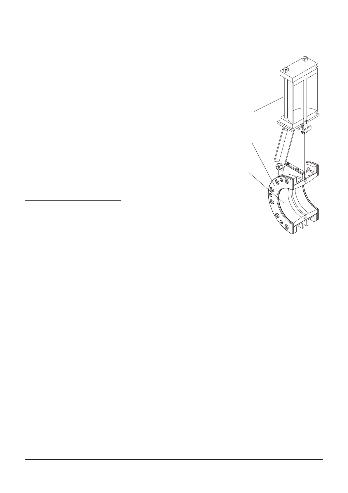
FIGURE 1
Operators
Retainer flanges
Sleeves
2

CLARKSON SLURRY KNIFE GATE VALVES - KGA+
INSTALLATION AND MAINTENANCE INSTRUCTIONS
3 INSTALLATION INSTRUCTIONS
Please take note of the specific installation
tagsprovided with each valve.
1. The KGA+ is installed with the gate in the
fully open position with the sleeves inserted
into the housing halves.
CAUTION
Valves are normally shipped with gate in
open position, the recommended position for
installation. Valves supplied with spring to extend
(fail close) cylinder actuators are shipped with
the gate in the closed position. Gate should be
actuated to the open position prior to installation,
exercise extreme caution when applying air
to open this valve and then ensure that it gate
lockedin the open position for installation.
2. The mating line flanges must be properly
aligned prior to attempting installation. Slip
on or weld flanges can be used. Never try to
make up for misaligned pipe flanges by the
line bolting. Pipe supports and/or expansion
joints should be used to minimize pipe
loads on valves. The pipeline companion
flanges should be raised or flat face type to
insure full sleeve support and a continuous
unvarying I.D. If slip-on flanges are used,
the pipe should be cut square and welded in
position with the pipe end matched evenly
with the flange face. Studded flanges are not
compatible with these valves. Tables 1 and2
state the maximum flange bolt tightening
torques. Listed in Table 3 are the fasteners
required for installation.
3. Sizes NPS 8 (DN 200) and below may or
may not have the optional retainer flanges.
Retainer flanges are standard on sizes
NPS 10 (DN 250) and larger. Ifnoretainer
flanges are used, the flanged end of the
sleeves form the gasket when installed
into the pipeline. When equipped with
retainer flanges, the elastomer coated
retainer flange functions as the gasket
forinstallation into the pipeline.
4. Valve is suitable for use in either vertical or
horizontal lines. The valve can be installed
in any position in vertical or horizontal
pipelines. However, valves installed in
an orientation with the actuator below
horizontal may require flushing to prevent
the buildup of solids in the housing and may
require additional actuator support.
5. Standard mating flanges NPS 3 - 24
(DN 80 - 600) match ASME B16.5/150,
sizesNPS 26 (DN 650) and largerare per
MSS-SP44 (see Table 1).
Installation notes
A. All slurry knife gate valves are designed and
manufactured to be installed in applications
where no more than 1 g of force in excess
of gravity is applied to the valve in any
direction. This 1 g force can be an effect
of traffic, wind, or earthquake, etc. Valves
should not be used in applications that
exceed 1 g.
B. If valve stem or topworks protrude into
walkways or work areas, valve should be
flagged per company safety policy.
C. All piping systems should contain
independent support mechanisms and
should not utilize the valve as a sole
meansof support.
D. Do not install valve over walkways, electrical
or other critical equipment without the use
of splash guards or similar considerations.
TABLE 1 - MAXIMUM TIGHTENING TORQUESTANDARD FLANGES
Valve size
ft·lb N·mNPS DN
3 80 37 50
4 100 37 50
6 150 69 93
8 200 69 93
10 250 113 153
12 300 113 153
14 350 169 229
16 400 169 229
18 450 238 322
20 500 238 322
24 600 345 467
26 650 345 467
30 750 345 467
36 900 610 827
42 1050 610 827
48 1200 610 877
54 1350 1000 1355
60 1500 1000 1355
TABLE 2 - MAXIMUM TIGHTENING TORQUE FRP FLANGES
Valve size
ft·lb N·mNPS DN
3 80 25 34
4 100 25 34
6 150 40 54
8 200 40 54
10 250 65 88
12 300 65 88
14 350 100 135
16 400 100 135
18 450 140 190
20 500 140 190
24 600 200 271
26 650 200 271
30 750 200 271
36 900 320 434
42 1050 320 434
48 1200 320 434
54 1350 600 443
60 1500 600 813
3

CLARKSON SLURRY KNIFE GATE VALVES - KGA+
INSTALLATION AND MAINTENANCE INSTRUCTIONS
TABLE 3 - BOLTING DIMENSIONS
Flange
Valve size
NPS DN inch mm inch mm UNC inch mm inch mm
3 80 7½ 190.50 6 152.40 4 ⅝ - 11 2 50.80 2½ 63.50
4 100 9 228.60 7½ 190.50 8 ⅝ - 11 2 50.80 2½ 63.50
6 150 11 279.40 9½ 241.30 8 ¾ - 10 2 50.80 2½ 63.50
8 200 13½ 342.90 11¾ 298.45 8 ¾ - 10 2¼ 57.15 2¾ 69.85
10 250 16 406.40 14¼ 361.95 12 ⅞ - 9 - - 3 76.20
12 300 19 482.60 17 431.80 12 ⅞ - 9 - - 4 101.60
14 350 21 533.40 18¾ 476.25 12 1 - 8 - - 4½ 107.95
16 400 23½ 596.90 21¼ 539.75 16 1 - 8 - - 4¾ 120.65
18 450 25 635.00 22¾ 577.85 16 1⅛ - 7 - - 5½ 139.70
20 500 27½ 698.50 25 635.00 20 1⅛ - 7 - - 5½ 139.70
24 600 32 812.80 29½ 749.30 20 1¼ - 7 - - 6 152.40
26 650 34¼ 869.95 31¾ 806.45 24 1¼ - 7 - - 6 152.40
30 750 38¾ 984.25 36 914.40 28 1¼ - 7 - - 7 177.80
36 900 46 1168.40 42¾ 1085.85 32 1½ - 6 - - 8½ 177.80
42 1050 53 1346.20 49½ 1257.30 36 1½ - 6 - - 9 203.20
48 1200 59½ 1511.30 56 1442.40 44 1½ - 6 - - 9½ 241.30
54 1350 66¼ 1682.80 62¾ 1593.90 44 1¾ - 5 - - 10½ 241.30
60 1500 73 1854.20 69¼ 1759.00 52 1¾ - 5 - - 11 266.70
diameter
Bolt circle
diameter Bolt holes
no.
Bolt
size/thread
Bolt lengths (see note)
Without retainer flg. With retainer flg.
NOTES
• Flange dimensions per ASME B16.5/150 for NPS 2 - 24 (DN 50 - 600) and MSS SP44 for NPS 26 - 60 (DN 650 - 1500).
• Type B standard washers are not included in bolt / stud sizing.
• Mating flange thickness assumed to match ASME B16.5/150 for NPS 2 - 24 (DN 50 - 600) and MSS SP44 for NPS 26 - 60 (DN 650 - 1500).
4 OPERATION
1. Clarkson slurry knife gate valves are
suitable for on-off service only. They are
notto be used in a throttling application.
2. To close the valve and provide isolation,
the actuator (handwheel, bevel gear,
air/hydraulic cylinder or electric motor
actuator) moves the metal gate in a linear
motion between the elastomeric sleeves
to shut off the flow. To open, reverse the
operation and the gate moves up and out
from between the sleeves, opening the
valveport.
3. Matching elastomer sleeves seal against
each under a high compression load
when the valve is open, creating the valve
pressure vessel. When the valve is closed,
the sleeves seal against the gate face,
isolating upstream from downstream.
SeeFigures 2 and 3.
Note: it is normal for the KGA+ to discharge
media during opening and closing cycles.
This helps prevent any solids from building
up between the sleeves that would prevent
a tight seal when the valve is fully open or
closed. Discharge can be controlled with
the use of an optional splash guard. Do not
install valve over walkways, electrical or
other critical equipment without the use of
splash guards or similar considerations.
4. As the gate strokes, a gap is created
between the facing sleeves, allowing any
media that could potentially clog or jam the
valve to be purged out from between the
sleeves, and potentially expelled outside
thevalve housing to atmosphere.
5. The KGA+ valve incorporates a built-in
clean-out area at the base of the housing
assembly. The clean-out area may be
enclosed by an optional, removable
splash guard assembly. This splash guard
will allow controlled drainage of any
accumulated solids that may prevent full
gate closure. Flush water can be used to
improve the drainage efficiency. With the
splash guard in place, any solids, slurry, or
flush water ejected from the valve can be
handled in a controlled manner. See Section
‘Installation instructions for splash guard’.
6. All valves should be operated within the
design pressure and temperature ranges.
Under no circumstances should the valves
be operated at conditions outside these
parameters.
Note: actuated Clarkson valves have a
maximum recommend stroke speed of
1” (25 mm) per second. Exceeding this
speed can shorten sleeve life and may
void warranty. Speed controls provided by
factory will require adjustment in the field
to obtain proper stroke speed against actual
operating conditions.
4
CLARKSON SLURRY KNIFE GATE VALVES - KGA+
INSTALLATION AND MAINTENANCE INSTRUCTIONS
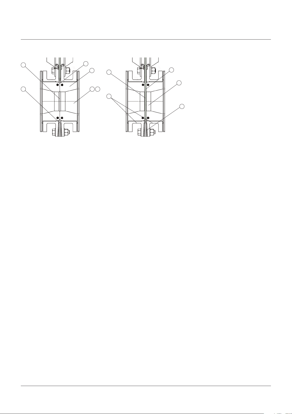
FIGURE 2 - OPEN POSITION FIGURE 3 - CLOSED POSITION
B
F
A
C
D
Open position
A. Gate positioned above seals, out of flow.
B. Matching elastomer sleeves seal against
each other under a high compression load.
C. Sleeves act as pressure vessel.
D. No metal parts in contact with slurry.
E. Unobstructed port area eliminates
turbulence, minimizes pressure drop
acrossvalve.
F. No seat cavity where solids can collect
andprevent full gate closure.
B
E
D
Closed position
A. Gate travels through sleeves to provide
blindflange shut-off, allowing opportunity
for media to expel to atmosphere.
B. 100% Isolation-bubble tight shut-off results
in absolutely zero downstream leakage.
C. When properly installed and maintained,
the KGA+ is designed to provide
man-safeisolation.
D. Double-seated design provides bidirectional
flow and shut-off.
E. Controlled stroke prevents gate from
penetrating too far, minimizing stress
onsleeve.
A
C
E
7. The operator of any valve should have an
understanding of the effects of opening/
closing the valve with regards to its role
in the overall piping system. Operators of
valves under pressure should take caution
to ensure that the valve is in good operating
condition prior to operating it under
pressure.
8. Certain processes contain hazardous and/or
otherwise unstable media. Care should be
taken in these circumstances to ensure the
operator is aware of the specific health and
safety risks associated with that medium.
9. When operating the valve stand clear of any
moving parts such as the stem and/or gate
assembly, use of gloves is suggested when
operating manual valves to minimize the
risk of injury.
10. All manually operated valves are designed
for hand input. Do not apply excessive input
torque via pipe wrenches, ‘cheater bars’,
or other devices. If a manual handwheel
actuated valve is difficult to operate due to
torque requirements, it is recommended
that the valve be supplied with or converted
to a bevel gear, air/hydraulic cylinder or
electric motor actuator.
11. Electric motor actuated valves should be
left in their factory set condition, unless
the system operating parameters dictate
a change. If changes are necessary, they
should be performed in small increments
using the lightest/lowest setting possible
to achieve the desired performance and
then the valve/actuator function inspected.
Excess torque and/or thrust in the motor
settings may damage or lockup the valve.
12. Clarkson KGA+ valves are position seated
and should never be torque seated. Do not
use the motor torque settings to seat the
valve.
13. Care should be taken to ensure that
electrical motors are wired correctly to the
power source. Incorrect phasing of 3-phase
wiring may cause valve/motor damage.
5
CLARKSON SLURRY KNIFE GATE VALVES - KGA+
INSTALLATION AND MAINTENANCE INSTRUCTIONS
5 LOCKOUTS
Lockouts are optional on the KGA+. If provided,
the open-closed lockout brackets are
designed to resist the normal valve operating
thrust. In order to assure complete lockout
compliance, any AC, HC or EM actuated valve
must be placed in a ZERO ENERGY STATE by
isolating all potential energy sources including
electricity, operator supply air or hydraulic
fluids. Please contact factory for complete
details.
CAUTION
Valves supplied with spring to extend (fail close) or
retract (fail open) cylinders contain a mechanical
spring which is compressed. In this case, the
mechanical energy of the compressed spring
cannot be placed in a ZERO ENERGY STATE.
Take extreme care when inserting and removing
the lockout pin. If the valve is actuated or the
opposing pneumatic force is removed during
the insertion process, the cylinder rod, gate and
accompanying hardware will move and injury
could occur.
6 GENERAL MAINTENANCE
We recommend that all Clarkson products be
inspected at least every 60 days. The following
points should be examined and corrected as
required:
1. Exterior overview: piping system
components are subject to certain levels of
erosion and corrosion. Periodic inspections
should be made as valves/components
may wear over time. Regular inspection
of the housing assembly and gate should
be performed, check for general signs
of corrosion, component wear and/
or damage caused by process media.
Severe applications may require additional
inspection types and/or frequency.
2. Valve stems, extension stems, and stem
nut: look for excessive corrosion, galling or
lack of lubrication. If valve stem requires
lubrication, utilize the grease fitting provided
and pump standard bearing grease through
the yoke hub to lubricate the stem and
stem nut assembly. Additional lubrication
may be applied directly onto stem or
stem threads. (Use material which meets
ASTM 4950 GBLB.)
3. If possible stroke the valve through the full
open and closed position to make sure it is
functioning properly.
Note: it is normal for the KGA+ valve to
discharge media during opening and
closingcycles.
4. Housing assembly and sleeve lubrication
A. A secondary seal is standard on the
KGA+ which provides the ability to
lubricate the gate and sleeve without
valve disassembly. Lubrication fittings
located in the upper chest of the valve
provide a direct path to the secondary
seal and serve as the primary means
ofgate and sleeve lubrication.
B. As a minimum, the Clarkson KGA+ valves
should be lubricated every 100strokes
for NPS 3 - 10 (DN80 - 250) sizes
and every 50 strokes for NPS 12 - 60
(DN 300 - 1500) sizes. An individual
application may require more or less
frequent lubrication depending on
the process and chemistry. If a valve
cycles very infrequently, less than once
per month, lubrication prior to each
stroke is recommended. (See below
forapprovedlubrication).
C. The gate may also be lubricated by
applying lubricant directly onto the
exposed gate surface.
D. Sleeve wear can be minimized if the
valve gate is scraped or wiped clean
occasionally.
E. For dry material handling service, the
secondary seal will not be provided and
liquid or grease type lubricants should
not be used.
NOTE
Failure to use the recommended type of lubricant
will considerably reduce the life ofboth the sleeves
and secondary seal. Under no circumstances should
a hydrocarbon-based lubricant be used. The use of
improper lubrication will void anyremaining warranty.
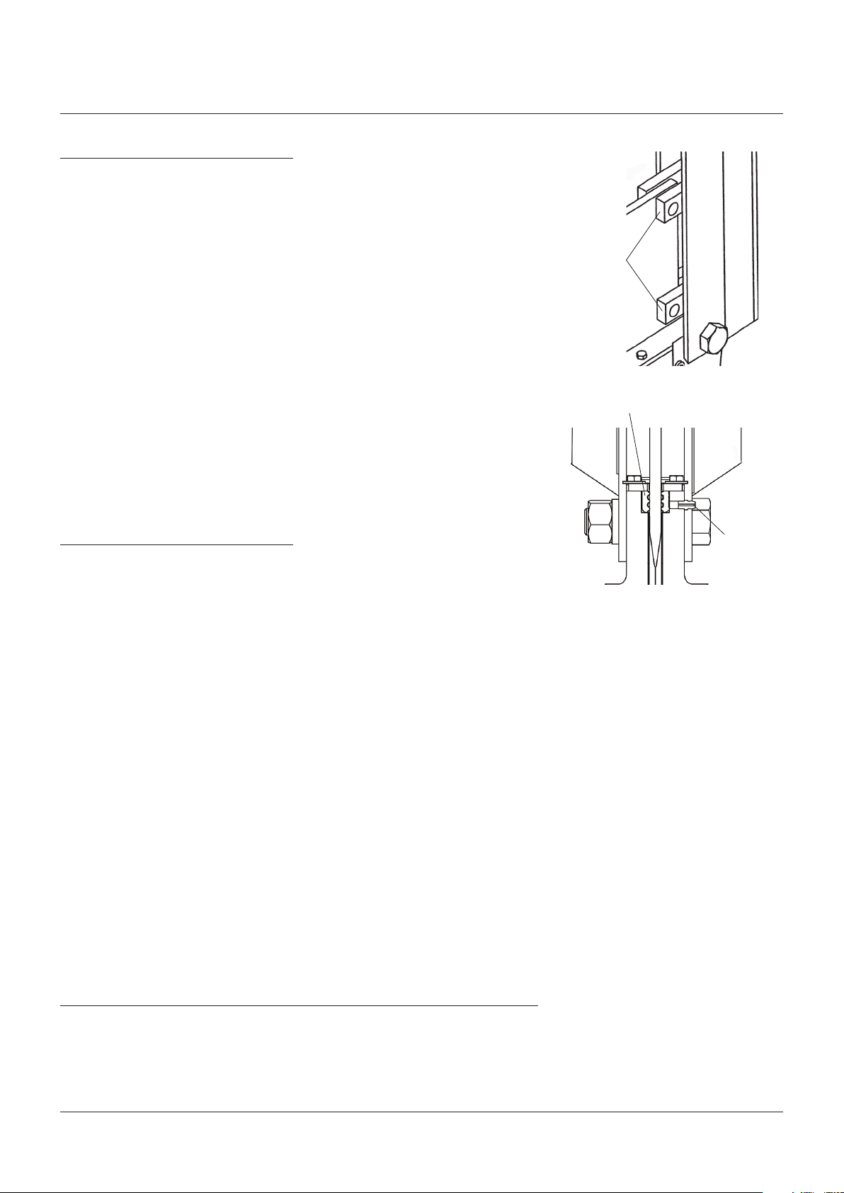
FIGURE 4
brackets
FIGURE 5
Lockout
Secondary seal
Lubrication
fitting
APPROVED SILICON BASED LUBRICANTS
Dow III - Dow corning Complex 821 - NFO
Dow 44 - Dow corning Dow 7 - Dow corning
Rhodorsil 111 - Rhone-poulenc Compound G661 - G E
Sil glyde - AGS Company
For compatibility of other lubricants, consult Emerson Engineering.
6
CLARKSON SLURRY KNIFE GATE VALVES - KGA+
INSTALLATION AND MAINTENANCE INSTRUCTIONS
7 SPARE PARTS
With the update to the KGA+, it is important
to understand the impact on spare parts and
interchangeability with the prior design. When
ordering spare parts, keep in mind the new
KGA+ uses the ‘plus’ sign as part of the model
code. This will allow quick identification to
assure proper spares are provided.
If tag is missing or unreadable, there are
several exterior clues to tell the difference
(refer to Figure 6):
KGA+: At the top of the valve housing, the
secondary seal retainer is a single
pieceand goes all-around the gate.
KGA: At the top of the valve housing, in place
of the secondary seal retainer, the KGA
has a wiper retainer. This is a two piece
assembly and the wiper (black plastic)
isvisible.
1. Encapsulated sleeves: no changes, 100%
interchangeability with all sizes.
2. Gates: to accommodate the new secondary
seal, gates have been redesigned for sizes
NPS 3 - 16 (DN 80 - 400). New gates for the
KGA+ sizes NPS 3 - 16 (DN 80 - 400) are
not interchangeable with the prior design
KGA and older gates will not fit the KGA+.
As a result, peripheral parts including gate
clevises, stem assemblies are also impacted
and not interchangeable in thesesizes.
3. Retainer flanges: no changes, 100%
interchangeability with all sizes.
4. Housings: all sizes have been redesigned to
accommodate the secondary seal, full face
flanges and spacer bar elimination. They are
not interchangeable with older housings.
Materials of construction remain the same.
5. Frames (yokes): no changes, 100%
interchangeability with all sizes excluding
special heavy duty designs.
6. Stem nut assembly: no changes, 100%
interchangeability with all sizes.
7. Handwheel: no changes, 100%
interchangeability with all sizes.
8. Stem nut base: no changes, 100%
interchangeability with all sizes.
9. Stem assembly: as noted above,
due to the gate redesign on sizes
NPS3 - 16 (DN80-400), stems are not
interchangeable. Sizes above NPS 16
(DN400) are 100% interchangeable.
10. Secondary seal: a wiper assembly is
standard on the KGA, the KGA+ uses
a secondary seal assembly, the two
assemblies are not interchangeable
between the two valve types.
11. Actuation: no changes have been
made to the AC or HC actuators, 100%
interchangeability. The clevis assembly
(gate to cylinder rod connection) has been
changed for sizes NPS 3 - 16 (DN 80 - 400)
and is not interchangeable. The BG actuator
remains the same; however, the stem
has been revised in sizes NPS 3 - 16
(DN 80 - 400) so it is not interchangeable
with prior designs.
Recommended spare parts (see Figure 7)
Valves:
2-replacement sleeves
1-replacement secondary seal
Cylinder operator (if applicable):
1-repair kit
1. When ordering replacement parts for a
Clarkson product or cylinder operator,
please include valve or cylinder size and
complete description including serial
number with your request.
2. Additional replacement parts such as
handwheels, stem nut assemblies,
retainers, frames (yoke), stems and gates
are available from factory. Again, please
provide complete description with serial
number when ordering.
3. Spare sleeve storage: molded elastomer
sleeves have a practical recommended
shelf-life. Genuine Clarkson sleeves are
laser etched on the outside surface with
date of manufacture to use in calculating
estimated shelf-life.
- Natural rubber - 2 years
- EPDM - 4 years
- NBR/HNBR - 4 years
Contact factory for additional elastomers.
FIGURE 6
Secondary seal retainer
KGA+, secondary seal retainer is a single piece,
goes all-around the gate, no spacer bar.
Wiper
retainers
Spacer bar
KGA, wiper retainer is two piece, wiper (black
plastic) is visible. Spacer bar is also visible.
FIGURE 7
Secondary seal
Sleeve
Wiper
7

CLARKSON SLURRY KNIFE GATE VALVES - KGA+
INSTALLATION AND MAINTENANCE INSTRUCTIONS
The shelf life listed is guideline data and is not
a substitute for examination of cured material
at the time of intended use.
To maintain shelf-life, spare sleeves should be
stored in accordance with the following.
1. Store at ambient temperature up to 80°F
(27°C), with 60 - 90% relative humidity away
from direct sunlight and at a minimum
distance of 15 feet (5 meters) away from
electric motors is mandatory.
2. Care must be taken to avoid storage in a
stressed condition such as piled too high or
on a plain pallet overhanging a sharp edge.
3. First in - first out inventory control should
be practiced.
4. The above elastomer shelf life guidelines
are for components that are not already
installed in a valve.
NOTE
Emerson recommends customers always use genuine
Clarkson OEM sleeves, secondary seals and other
replacement parts to maintain the expected, superior,
performance of their KGA+. Genuine Clarkson
sleeves and secondary seals from Emerson are easily
recognized by the laser etched identifying marks found
on the outside surface. These marks include the size,
part number, applicable patent number, elastomer
batch compound and date of manufacture; all of
which allow complete traceability of the part. Clarkson
replacement sleeves, secondary seals and other parts
from Emerson are the only ones authorized for use
and offer the best fit and continued performance that
non-OEM parts simply cannot give. The use of copycat
parts may invalidate any remaining warranty. If valve
requires further repair, please contact our office for
an estimate of feasibility and cost ofrepair.
8 STORAGE
The following are the factory’s
recommendations for storage procedures to
retain maximum product integrity during long
term storage of 1 to 5 years.
1. Valves are normally shipped with gate in
open position, the recommended position
for storage. During storage, the gate should
always be in the open position. Storage
should be in an area out of direct sunlight,
away from heat, ozone and extreme weather
conditions. Freezing is not considered
detrimental as long as the valve is kept
dry. High voltage rectifiers and other ozone
generating equipment and sources should
not be near the storage area.
CAUTION
Valves supplied with spring to extend (fail close)
cylinder actuators are shipped with the gate in
the closed position. DO NOT store a KGA+ with a
spring to extend (fail close) in the open position.
This would put the spring in a compressed,
fully energized position. For storage, it is
recommended the valve sleeves be removed from
the valve housing and stored separately from the
valve. Reinsert sleeves prior to installation.
2. The preferred storage location is a clean,
dry protected warehouse. If valves are to
be stored outside, precautions should be
taken to keep valves clean and dry. Standard
packaging materials provided in valve
shipment cannot be considered sufficient
for outdoor storage.
3. If outdoor storage is required, the
equipment should be totally covered with
a heavy, light colored, plastic covering.
It is essential that the plastic be opaque
to eliminate sunlight, and light colored
to minimize heat buildup. The covering
should be spread in a manner that allows
underside ventilation. To insure proper
ventilation the equipment should be
elevated 2” - 4” (50 - 100 mm) above the
ground.
4. Manual actuated valves may be stored in
the vertical or horizontal position. For air
or hydraulic actuated valves, the preferred
orientation for optimum protection is with
the valve fully opened and the cylinder in
the vertical position. This position gives
the best support to the cylinder rod and
helps reduces the chance of a ‘flat spot’
developing on the cylinder seals. An
acceptable alternate position for valves with
cylinder diameters of less than 6” (150 mm)
is with the cylinder in the horizontal position.
Motor actuated valves should be oriented
in the direction as preferred by the actuator
manufacturer.
5. Valves with cylinder and motor actuators
should be stored in accordance with
actuator manufacturer’s recommendations.
Access ports or panels should be secured
to prevent unauthorized entry and prevent
contamination.
6. Where auxiliary equipment is included,
such as limit switches, solenoid valves, etc.,
care must be taken to avoid moisture and
condensation conditions on the equipment.
7. Storage inspection: visual inspection shall
be performed on a semiannual basis and
results recorded. Inspection as a minimum
shall include reviewing the following:
- Packaging
- Flange covers
- Dryness
- Cleanliness
8. Maintenance shall consist of correcting
deficiencies noted during inspection. All
maintenance shall be recorded. Contact
factory prior to performing any maintenance
if valve is still covered under warranty.
8

CLARKSON SLURRY KNIFE GATE VALVES - KGA+
INSTALLATION AND MAINTENANCE INSTRUCTIONS
9 SLEEVE REPLACEMENT
NOTE
Sizes NPS 8 (DN 200) and below may or may not
have the optional retainer flanges. Retainer flanges
are standard on sizes NPS 10 (DN 250) and larger.
Larger diameter valves are supplied with segmented
(multipart) retainer flanges. If your valve has
segmented retainer flanges, take note of the special
sections.
Inspection of components
1. Verify that for each valve there are two(2)
sleeves, two (2) retainer flanges (if required),
retainer flange bolts and nuts (if required).
KGA+ NPS 30 - 60 (DN 750 - 1500), use
segmented retainer flanges. Refer to
the Clarkson certified parts list for the
appropriate valve size to determine the
quantity of retainer flange nuts and bolts
required.
2. Visually inspect each sleeve and retainer
flange for damage to surfaces resulting
from shipping or post-shipping handling.
The sealing surfaces (nose) must be free
ofdepressions, slits or gouges.
Disassembly
1. Before working on the KGA+ valve, verify
that the valve is in the open position. If it
isnot, move it to the open position.
CAUTION
Assure line is not pressurized before removing
valve. Valve assembly and parts may be heavy,
use proper lifting and support techniques.
SeeSection15, Lifting.
2. Remove the valve from the piping.
3. Visually inspect and verify that the sleeve
bore is clear of all debris, scale and
elastomer residue.
4. Remove the retainer flange bolts taking
caution to prevent retainer flanges from
falling free if in vertical position. Remove
theretainer flanges from the valve.
5. For valves with segmented retainer flanges
(see Figure 9), loosen retainer bolts and pull
each individual segment straight up away
from the valve, do not remove more than
one section at a time.
6. Remove the two elastomer sleeves by
simply pulling each sleeve out of the
housing assembly. (Sometimes a putty knife,
large screwdriver or pry bar is necessary to
pry the retainer flange away from the sleeve
and the sleeve from the valve flange.)
Installation
1. Lay valve down in a horizontal position, on
a flat surface. (While it is possible to install
valve sleeves with assembly in vertical
position, this may make it more difficult
to properly align the retainer flanges and
sleeves, especially on larger valves.)
2. Check the bore diameter for unusual or
excessive wear. If found, valve housing
mayrequire replacement.
3. Table 4 shows the maximum / minimum
bore dimensions of a new KGA+ valve, along
with the maximum allowable diameter
figures of a housing affected by wear and
usage. If housing is not within the maximum
allowable range, it is recommended that the
housing be replaced before installing new
sleeves. In some cases, it may be possible to
make minor repairs to the housing in order
to continue using it. Please contact the
factory for information.
4. Lubricate the O.D. of the seal end of
thesleeve.
5. Install the sleeve, being careful to center
theflange end in the bore of the housing.
6. Place a retainer flange on the top of the
sleeve. Align the retainer flange bolt holes
with the matching holes in the round
flange. Align the I.D. of the sleeve and
retainerflange.
7. For valves with segmented retainer flanges,
position one retainer flange segment on the
sleeve lip. Align with proper mounting holes
in the round flange. Install the required
bolts and nuts; hand tight. Position the next
segment on the sleeve lip opposite the one
previously installed. Install fasteners as
before. Continue to install segments in this
manner until complete flange is in position.
8. Install the retainer bolts. Only tighten
sufficiently to allow installation of the
next bolt. Continue this until all bolts
areinstalled.
9. Once all bolts are in place, tighten the
retainer flange bolts using a cross pattern
until there is a 0” - ⅛” (0 - 3 mm) gap
between the retainer flange and the
housing. Do not cycle valve with only one
sleeve in place.
NOTE
Certified Clarkson elastomer parts from Emerson are
laser-etched with part number, date of manufacture,
the Clarkson brand name and other appropriate
information to assure you have a genuine Clarkson
part. The use of non-OEM parts will void any
remaining warranty.
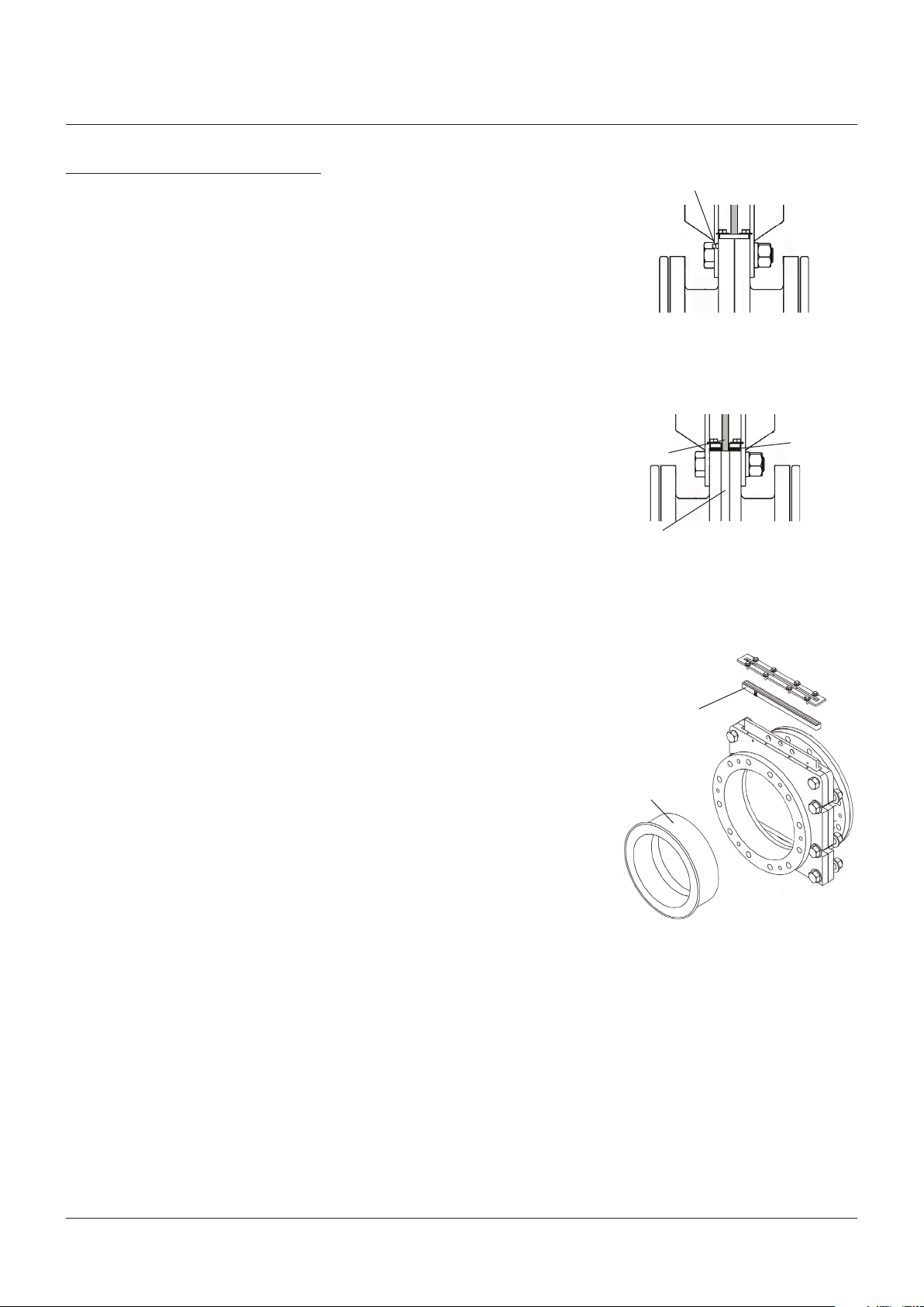
FIGURE 8
Sleeve
Retainer
Retainer bolts/nuts
9
CLARKSON SLURRY KNIFE GATE VALVES - KGA+
INSTALLATION AND MAINTENANCE INSTRUCTIONS
10. Turn the valve over so the installed sleeve
ison the flat surface.
11. Apply a silicone base lubricant to the
sealing-nose radius of the installed sleeve.
Also apply it to the second sleeve sealing
nose and O.D. of seal end.
12. Install the second sleeve, following steps
1through 11. It may be necessary to use two
or more C-clamps to pull down the second
retainer flange. Do not fully tighten retainer
flange bolts until after checking the sleeve
bores for concentricity; using a straight
edge, check the sleeve position in four (4)
places, 90 degrees apart in relation to the
installed sleeve bore I.D. Adjust as required
to make the sleeve concentric with the
othersleeve.
13. Fully tighten retainer flange bolts per
Paragraph 9.
14. Remove C-clamps, if used.
15. The valve is now ready for installation.
Keep gate in the open position until valve
isinstalled.
10 SECONDARY SEAL REPLACEMENT
CAUTION
Since this procedure may be performed with the
valve in an active pipeline, plant standard safety
procedures must be followed. Use of personal
protective equipment, tag out or other plant
standard safety procedures must be followed.
Procedure SHOULD NOT be done with valve in
closed position. If valve is removed for this service,
assure line is not pressurized before removing
valve. Valve assembly and parts may be heavy,
use proper lifting and support techniques, refer
toLifting, Section 15.
Disassembly
1. Replacement of the secondary seal can be
accomplished without having to remove the
valve from service, however, this procedure
SHOULD NOT be done with valve in closed
position. If it is suspected that either one or
both of the elastomer sleeves have failed,
the valve should be removed from service
before secondary seal removal. If valve is
tobe removed, refer to Lifting section.
2. Open the valve, so the gate is in the fully
raised position.
3. For ease of reassembly, using a permanent
marker, draw a line on the gate face along
the top of the secondary retainer plate. If
marking gate is not an option, make note
of the dimension from top of valve housing
to top of gate in full open position (refer to
Table 5, Figure 13, dimension A).
4. Remove the cotter pin from the clevis pin
and remove the clevis pin from the gate. It
may be necessary to actuate the valve down
slightly in order to relieve pressure on the
clevis pin to facilitate removal.
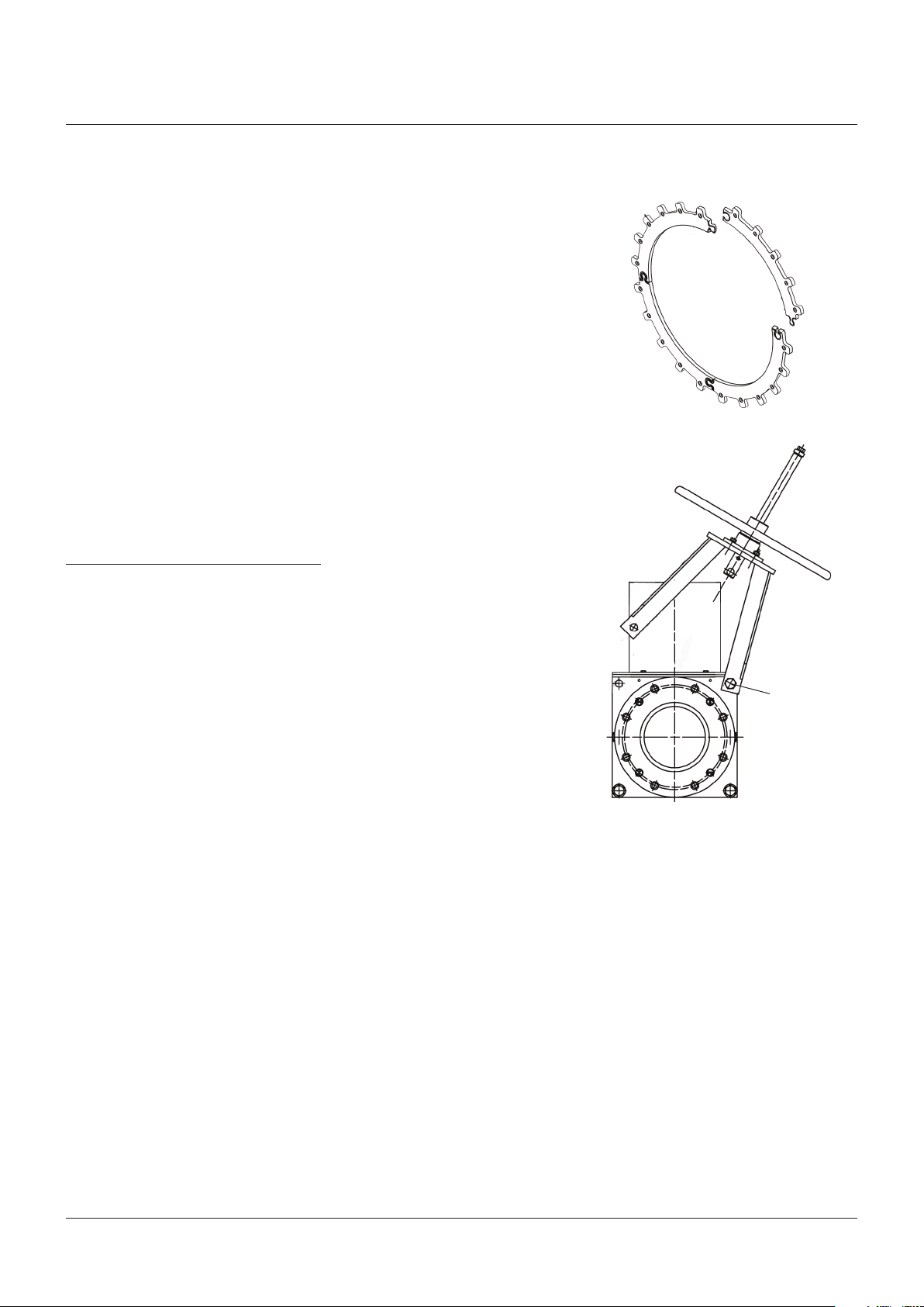
5. Actuator assembly removal:
Smaller valves: remove the frame to
housing bolts of one side except for the
lowest bolt on the opposite side of the frame
(see Figure 10). This bolt will act as a pivot
point for the frame / actuator assembly.
While supporting the actuator assembly,
pivot the frame / actuator assembly away
from the valve. Continue to provide support
while actuator is in this position.
Larger valves: remove the frame to housing
bolts. Lift the frame and actuator assembly
off the housing assembly to allow secondary
seal and gate removal.
6. Loosen the secondary seal retainer plate
bolts.
7. Remove the gate by lifting it out of the
secondary seal.
8. Remove all fasteners and lockwashers that
retain the secondary seal retainer plate in
position.
9. Remove the secondary seal retainer plate
bylifting it up.
10. Remove the secondary seal by inserting a
flat blade screwdriver midway along the
outside of the seal, between the seal and the
valve housing. Pry the seal up and remove.
11. Inspect the gate for sharp edges or
excessive damage. Refer to ‘Gate
replacement’ section if gate requires
replacement.
FIGURE 9
Example of a segmented retainer
FIGURE 10
Pivot frame
on bolt
For gate and or secondary seal replacement,
smaller valves may have the actuator frame
swung out of the way as illustrated here.
Remove frame bolts on one side only and
loosen the opposite side just enough to allow
movement. Be sure and properly support
weight of actuator assembly, taking care to
avoid injury.
10

CLARKSON SLURRY KNIFE GATE VALVES - KGA+
INSTALLATION AND MAINTENANCE INSTRUCTIONS
Reassembly
1. If valve has been removed from pipe, lift
valve to vertical position, refer to Lifting,
Section 15.
2. Using DOW III or approved alternate,
completely fill all internal cavities of the
newsecondary seal.
3. Insert the new lubricated secondary seal
into the valve housing assembly. Make sure
that the lube path openings on the seal line
up with corresponding external housing
lubrication fittings.
4. Place the secondary seal retainer plate
intoposition.
5. Replace and hand tighten all the retainer
plate fasteners and lockwashers.
6. Apply a small amount of recommended
lubricant to the two tapered faces of the
‘sharp end’ of the gate.
7. Press the gate firmly through the secondary
seal into the valve housing assembly until
the mark drawn on the gate reaches the
top of the retainer plate or gate reaches
dimension A, Table 5, Figure 13.
8. Fully tighten all the retainer plate fasteners.
9. Reinstall the actuator / frame assembly with
the housing / frame fasteners loosely.
10. Reconnect the gate to the actuator. (In order
to facilitate installation and future removal,
a coating or anti-seize compound should be
applied to the outside of the clevis pin over
the yoke contact area).
11. ‘Stretch’ the frame / actuator assembly
with respect to the housing by pulling (not
lifting) the frame / actuator assembly to
its maximum movement away from the
housing assembly (holding housing in place
if valve is removed from pipeline). Tighten
the frame/ housing bolts and verify the
tightness of the actuator to frame bolts.
12. Cycle valve to full open position and check
the gate position using the data in the
Table5, Figure 13. Adjust as required.
13. Rattle the gate. It should be mostly
disengaged from the sleeves. The outboard
edges of the gate should be free and the
center still partially engaged in between
thesleeves.
14. Cycle gate full closed and full open.
15. Inspect gate for pieces of rubber. If
significant amount of rubber is present, a
sharp edge(s) on the gate may be causing
seal damage or the gate is extending too
far on the up stroke. The ends of the gate
should be free and the center still engaged.
If the sleeve / gate is misaligned, loosen the
frame actuator bolts and / or adjust the yoke
until the proper position, open and closed,
isobtained.
16. If out of pipeline, reinstall the valve, refer
toLifting, Section 15.
FIGURE 11
Secondary
sealretainer
Secondary
seal
TABLE 4 - HOUSING I.D.
Maximum allowable
Valve size I.D. minimum I.D. maximum
NPS DN inch mm inch mm inch mm
3 80 4.45 113.03 4.49 114.05 4.55 115.57
4 100 5.39 136.91 5.43 137.92 5.49 139.45
6 150 7.79 197.87 7.83 198.88 7.89 200.41
8 200 9.42 239.27 9.46 240.28 9.52 241.81
10 250 11.92 302.77 11.96 303.78 12.02 305.31
12 300 13.94 354.08 13.97 354.84 14.00 355.60
14 350 15.80 401.32 15.83 402.08 15.86 402.84
16 400 17.44 442.98 17.47 443.74 17.50 444.50
18 450 19.06 484.12 19.10 485.14 19.19 487.43
20 500 21.06 534.92 21.10 535.94 21.19 538.23
24 600 26.06 661.92 26.10 662.94 26.19 665.23
26 650 28.28 718.31 28.36 720.34 28.45 722.63
30 750 32.06 814.32 32.12 815.85 32.21 818.13
36 900 38.20 970.28 38.30 972.82 38.39 975.11
42 1050 45.06 1144.52 45.19 1147.83 45.31 1150.87
48 1200 50.74 1288.80 50.77 1289.56 50.89 1292.61
54 1350 55.74 1415.80 55.77 1416.56 55.89 1419.61
60 1500 63.95 1624.33 63.99 1625.35 64.11 1628.39
housing I.D.
11

CLARKSON SLURRY KNIFE GATE VALVES - KGA+
INSTALLATION AND MAINTENANCE INSTRUCTIONS
11 DISASSEMBLY AND ASSEMBLY INSTRUCTIONS
NOTE
Sizes NPS 8 (DN 200) and below may or may not
have the optional retainer flanges. Retainer flanges
are standard on sizes NPS 10 (DN 250) and larger.
Larger diameter valves are supplied with segmented
(multipart) retainer flanges. If your valve has
segmented retainer flanges, take note of the special
sections.
CAUTION
Valve assembly and parts may be heavy, use
proper lifting and support techniques, refer
toLifting, Section 15.
Disassembly
1. Before working on the KGA+ valve, verify
that the valve is in the open position. If it
isnot, move it to the open position.
2. Remove the valve from the piping.
3. For ease of reassembly, using a permanent
marker, draw a line on the gate face along
the top of the secondary retainer plate. If
marking gate is not an option, make note
of the dimension from top of valve housing
to top of gate in full open position (refer to
Table 5, Figure 13, dimension A).
4. Visually inspect and verify that the sleeve
bore is clear of all debris, scale and
elastomer residue.
5. Remove the retainer flange bolts taking
caution to prevent retainer flanges from
falling free if in vertical position. Remove
theretainer flanges from the valve.
6. For valves with segmented retainer flanges
(see Figure 9), loosen retainer bolts and pull
each individual segment straight up away
from the valve, do not remove more than
one section at a time.
7. Remove the two elastomer sleeves by
simply pulling each sleeve out of the
housing assembly. (Sometimes a putty knife,
large screwdriver or pry bar is necessary to
pry the retainer flange away from the sleeve
and the sleeve from the valve flange).
8. Remove the cotter pin from the clevis pin
and remove the clevis pin from the gate. It
may be necessary to actuate the valve down
slightly in order to relieve pressure on the
clevis pin to facilitate removal.
9. Remove the actuator/frame subassembly at
one time by removing the frame bolts that
fasten the frames to the housing and pulling
it away from the housing assembly.
10. Loosen the secondary seal retainer plate
bolts.
11. Remove the gate by lifting it out of the
secondary seal.
12. Remove all fasteners and lockwashers that
retain the secondary seal retainer plate in
position.
13. Remove the secondary seal retainer plate
bylifting it up.
14. Remove the secondary seal by inserting
aflat blade screwdriver midway along the
outside of the seal, between the seal and the
valve housing. Pry the seal up and remove.
15. Remove housing bolts, and pull halves
apart.
Note: the KGA+ does not have spacer plates.
16. Remove old housing gaskets (two).
12
 Loading...