

CLARKSON FIGURE 215 SLIDE GATE VALVE
INSTALLATION AND MAINTENANCE INSTRUCTIONS
Before installation these instructions must be fully read and understood
WARNING
The user is responsible for correct directional
installation.
On select applications, greater performance
may be realized by installing a unidirectional
valve in the reverse flow position, contact
factory for details.
Packing assembly: the packing gland bolts
should be checked and adjusted to obtain a
first time packing seal. Packing gland bolts
may become slightly loose when valve is
shipped. Field adjustment is expected and
desired. (Tighten just enough to stop any
leakage. Overtightening may increase valve
operating torque and shorten packing life.)
The Figure 215 is equipped with two packing
assemblies.
GENERAL INFORMATION
Thank you for purchasing a Figure 215 slide
gate valve from Emerson. With proper care it
should provide you a long service life.
Valve types: standard Figure 215 is
UNIDIRECTIONAL (one-way shut-off). UniDirectional valves have a preferred shut-off
direction, however, they will handle flow in
both directions without concern.
WARNING
Care must be taken in valve installation with
respect to direction of flow.
Uni-Directional valves have the preferred
direction of shut-off indicated by the word
"SEAT" stamped on the upper right hand
corner of the gate on the seat side or a flow
arrow (pointing toward the preferred direction).
A unidirectional valve is normally installed with
the seat side (preferred direction) downstream,
with the line pressure pushing the gate toward
the seat.
Operators: standard manual handwheels
are shipped loose for field installation. It
is necessary to use a pipe wrench or large
crescent wrench to properly tighten the
handwheel retaining nut. Be sure to fully
tighten.
If valve is supplied with other than standard
handwheel operator, additional support may
be required, especially if valve is other than
vertical. See page 6 for further details.
Bolting: the mating line flanges must be
properly aligned. Slip on or weld flanges can be
used. Never try to make up for misaligned pipe
flanges by the line bolting. Pipe supports and/
or expansion joints should be used to minimize
pipe loads on valves.
Most Figure 215 valves are suitable for use in
either vertical or horizontal lines. If operator
is other than vertical, additional support may
be required if valve is not handwheel operated.
For horizontal pipes with valves mounted with
the stem horizontal, additional wear strips may
be required. Consult factory.
VCIOM-08489-EN 19/09Emerson.com/FinalControl © 2018 Emerson. All Rights Reserved.

CLARKSON FIGURE 215 SLIDE GATE VALVE
INSTALLATION AND MAINTENANCE INSTRUCTIONS
INSTALLATION INSTRUCTIONS
Please take note of the specific installation tags
provided with each valve.
The mating line flanges must be properly
aligned. Slip on or weld flanges can be used.
Never try to make up for misaligned pipe
flanges by the line bolting. Pipe supports and/or
expansion joints should be used to minimize
pipe loads on valves.
Most Figure 215 valves are suitable for use in
either vertical or horizontal lines. If operator
is other than vertical, additional support may
be required if valve is not handwheel operated.
For horizontal pipes with valves mounted with
the stem horizontal, additional wear strips may
be required. Consult factory.
Bolting and installation instructions for
standard slide gates
(Valves with drilled and tapped flange mounting
holes)
All standard Class 150 Figure 215 valves
are “flanged” design. The port flanges of the
valves NPS 2 to 24 are drilled and tapped to
ASME B16.5/150. The valves are normally
provided in the MSS standard face-to-face with
the port flange bolt holes drilled and tapped.
The bolt holes in the chest or upper flange
area are blind tapped, see Figure 1.
WARNING
Care must be taken when installing studs or bolts
in the tapped holes of the flange in the valve chest
area to prevent damage.
Cap screws or bolts that are too long can
pinch the valve body, thereby forcing it into
the gate and springing the gate out of line.
Additional damage can occur on the gate face,
such as scoring or scratching of the gate. This
type of damage normally requires the valve
be returned to our shop for repair. To avoid
damage, it is recommended that studs be used
on all tapped bolt holes, especially the upper
chest holes. If cap screws are used, be sure
that they do not enter beyond the depth of the
tapped hole when fully tightened. See Table
A for flange thicknesses of MSS face-to-face
knife gate valves.
MAXIMUM FLANGE BOLT TORQUES (ft·lbs)
Size Torque Size Torque
⅝ 55 +/-5 1⅛ 150 +/-5
¾ 65 +/-5 1¼ 200 +/-5
⅞ 110 +/-5 1½ 250 +/-5
1 135 +/-5
FIGURE 1
Cap screw Stud with nut
Incorrect
Correct
2
CLARKSON FIGURE 215 SLIDE GATE VALVE
INSTALLATION AND MAINTENANCE INSTRUCTIONS
TABLE A - MSS-SP81 DIMENSIONS
Valve
size
Flange
outside dia.
[1]
Raised
face o.D.
[1]
Bolt circle
[1]
dia.
Bolting dimensions
No. of bolts Tap size
[1,3]
Face to
face
thickness
2 6 3⅝ 4¾ 4 ⅝ - 11 NC 1⅞ ½
3 7½ 5 6 4 ⅝ - 11 NC 2 ½
3
4 9 6
5 10 7
/
16 7½ 8 ⅝ - 11 NC 2 ½
5
/
16 8½ 8 ¾ - 10 NC 2¼ ⅝
6 11 8½ 9½ 8 ¾ - 10 NC 2¼ ⅝
8 13½ 10⅝ 11¾ 8 ¾ - 10 NC 2¾ ⅝
10 16 12¾ 14¼ 12 ⅞ - 9 NC 2¾ ¾
12 19 15 17 12 ⅞ - 9 NC 3 ¾
14 21 16¼ 18¾ 12 1 - 8 NC 3
16 23½ 18½ 21¼ 16 1 - 8 NC 3½ ⅞
18 25 21 22¾ 16 1⅛ - 7 NC 3½
20 27½ 23 25 20 1⅛ - 7 NC 4½ 1
24 32 27¼ 29½ 20 1¼ - 7 NC 4½ 1
NOTES
For larger size valves, refer to the customer drawing.
1. These dimensions duplicate Class 150 of ASME B16.5 to facilitate mating.
1
2. Flange thickness includes
/
16" raised face.
3. Hole size dimensions for through bolting shall conform to Class 150 of ASME B16.5.
4. All dimensions are in inches.
Flange
13
/
16
15
/
16
[2]
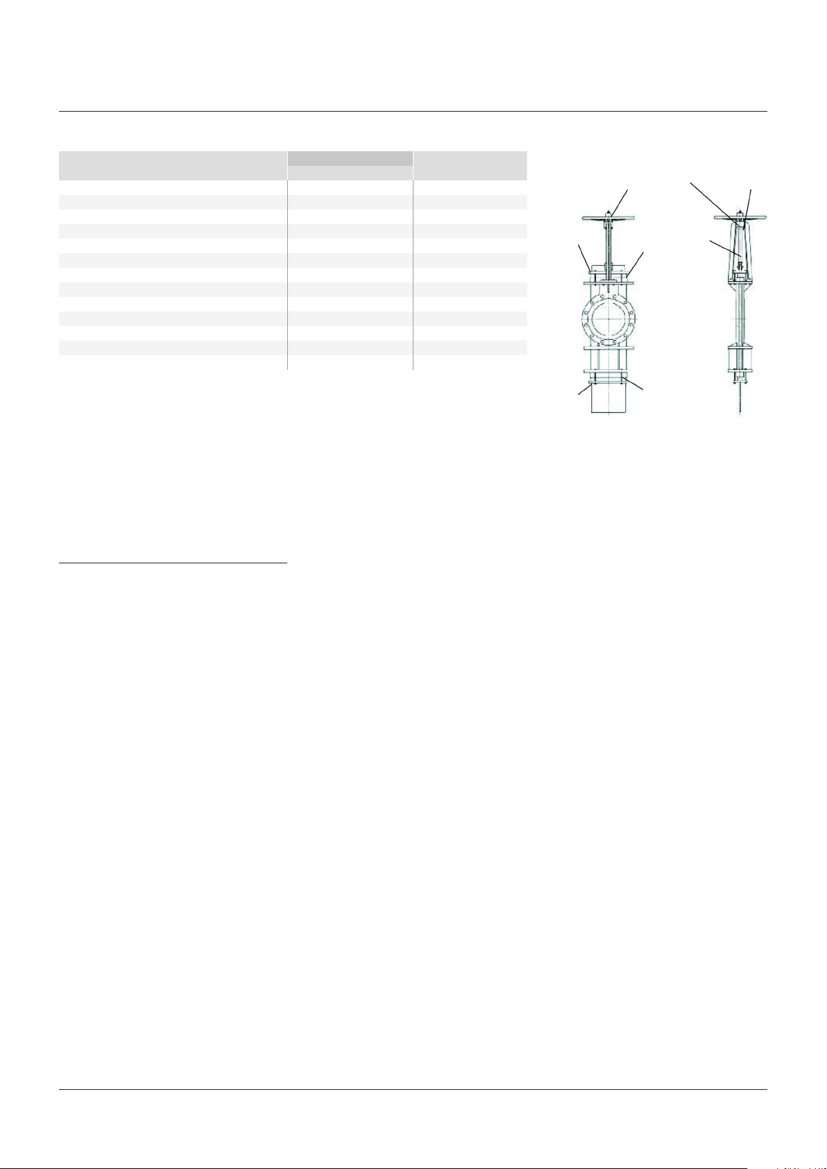
FIGURE 2
Packing
gland
Packing
gland
Umbrella nut
(stop stud)
Packing
Packing
Grease
fitting
Stem
Stem nut
GENERAL MAINTENANCE
The factory recommends that all Figure 215
valves be inspected at least every 60 days.
The following points should be examined and
corrected as required:
1. Valve stems, extension stems, and stem
nut: look for excessive corrosion, galling or
lack of lubrication. If a valve stem requires
lubrication, utilize the grease fitting provided
and pump standard bearing grease through
the yoke hub to lubricate the stem and stem
nut assembly. Additional lubrication may be
applied directly onto stem or stem threads.
(Use material which meets ASTM 4950
GBLB). See Figure 2.
2. Packing glands: check for leaks or worn
packing. If leakage is occurring around the
packing gland, tighten the packing gland
bolts, being careful not to overstress the
bolting. On some valves this will require two
wrenches, one to tighten the nut and the
other to hold the packing bolt from turning.
If the valve requires repacking, you may
use any standard square braided packing
as suitable for your service. See additional
instructions for repacking on page 5 for
bonnetless valves.
3. If possible, stroke the valve through the full
open and closed position to make sure it is
functioning properly.
NOTES
1 Stop all small leaks as soon as possible as
considerable damage can be done to the valve
and the surrounding area if leakage is allowed to
continue to grow.
2. Replacement parts including handwheel and yoke
assemblies, gates, packing glands, and packing
can be provided from our factory. If valve requires
further repair, please contact our office for an
estimate of feasibility and cost of repair.
3
 Loading...