

Clarkson Knife Gate Valves Figure 955/956 Storage/Installation Instructions, Clarkson-EN Manuals & Guides

CLARKSON KNIFE GATE VALVES
FIGURE 955/956
Storage and installation instructions for F955 ported slide gate valves and F956 dual gland ported slide gate valves
STORAGE
IMPORTANT
Do not remove any identification or instruction
tags from the valve assembly.
For optimum protection, undercover storage is
desirable.
Valves
Flange faces should be protected at all times
with wooden, or heavy cardboard shields.
Valves should be handled carefully to prevent
damage to exterior protective coating. Flange
bolt holes should be coated with a suitable
rust inhibitor for prolonged or exterior storage.
Careshould be taken in the placement of valves
in storage to assure excessive pressure is not
placed on polymer body shrouds or spindle
covers so as to cause component damage.
F955 valves should be stored in the closed
position.
F956 valves should be stored in the open
position.
Handwheel spindle thread should NOT be
lubricated as dirt will accumulate in threads.
Actuators
All air line and electrical cable entries should
be plugged to prevent the ingress of foreign
material. Actuator cylinders, where not fitted
to a valve, should be stored with the piston rod
fully retracted. Internal cylinder components
should not require any corrosion inhibitor as
they are assembled with a light coating of
grease.
INSTALLATION INSTRUCTIONS
Heavy valves will require a chain block
or crane to assist in the installation.
Indifficultinstallations, large actuator
cylinders may be removed from the valve
andre-fitted after installation. When re-fitting
the actuator cylinder care must be taken
to ensure the cylinder/valve alignment is
maintained (refercylinder fitting instruction
sheet). Largeractuated valves installed in
vertical pipework will require structural
support to takethe weight of the actuator.
Thissupportmay also be desirable in larger
valves installed in non-vertical positions.
The F955/F956 is configured for installation
in conventional bolted flange connections.
Flanges are required to support the seat by
presenting a flat surface across the seat. If
the flange does not present a flat surface
then companion flanges can be used. The
companion flanges should be raised or flat
face type to ensure full sleeve support and a
continuous, unvarying I.D. If slip-on flanges
are used without companion flanges, the pipe
should be cut square and welded in position
with the pipe end matched evenly with the
flange face. (see below diagram)
A B
SAFETY PRECAUTIONS
Actuated valves are generally operated from
aremote location.
Caution should be exercised when working in
close proximity to these valves. The F955/F956
valves are supplied with upper body shrouds
and spindle covers for environmental and safety
purposes.
To ensure the long term operation and safety
of the valves, the covers and shrouds must be
maintained at all times.
CAUTION
Care must be taken with the installation of the
F955/F956 valve to resilient faced companion
flanges. Excessive tightening of the flange bolts
will result in severe valve seat damage on valve
actuation. Companion flange bolts must only be
tightened asnoted below.
1. Close valve.
2. Check the valve size is correct and there
isadequate clearance to install the valve.
3. Check valve and pipe flange faces are clean
and smooth, and that the valve bolt pattern
is the same as the flange.
4. Check flange bolt sizing and ensure the bolt
threads are clean (separate technical data is
available).
5. Check the alignment of the upstream and
downstream pipes and the squareness
ofthe pipe flanges.
Spare parts
Seats, cord and packing should be carefully
stored and protected from sharp edges or
heavy objects which could damage sealing
faces.
TYPICAL VALVE INSTALLATION WITH
SCHEDULE 40 PIPE SHOWN.
A) Example of incorrect installation:
Void area of pipe flange/pipe connection
does not support seat sufficiently. Fillet weld
between pipe and flange shown creates this
void area. Thin walled pipes can also fail to
support seats.
B) Example of correct installation:
The inside diameter of the pipe/flange is
Schedule 40 pipe inside diameter or less. The
pipe/flange presents a flat face to the seat.
© 2017 Emerson. All Rights Reserved.valves.emerson.com VCIOM-02872-EN 19/09
CLARKSON KNIFE GATE VALVES
FIGURE 955/956
NOTE
If rubber coated pipe flanges are being used, the steel
flange rings (minimum thickness of valve DN 50 - 200
(NPS 2 - 8) of 3 mm (0.12 inches) and DN 250 - 750
(NPS 10 - 30) of 5 mm (0.20 inches)) must be fitted on
both sides of the valve and ensure correct opperation
of seats.
6. Do not use flange gaskets with these valves
as the seats form the seals.
7. Spread pipe flanges to clear valve, lower
valve into position taking care to prevent
damage to the valve seat flange as the valve
is being lowered.
8. Liberally coat all flange bolt threads with an
effective rust inhibitor/anti-seize compound,
and install all flange bolts. Tighten bolts
in a diagonally opposed sequence (see
Figure2) to assure even tightening of the
flange faces. Ensure bolts in the chest
area of the valve is not bottoming out in the
blind holes. If the valve is being installed to
resilient faced flange(s) care must be taken
to assure the flange bolts are only tightened
sufficiently to allow the resilient facing to
contact the machined valve body face.
9. Ensure the valve flushing system is
operational prior to cycling the valve with
process pipeline media's.
10. Cycle the valve several times, checking for
correct valve operation.
11. After pressurisation of the pipeline, check
flanges and gate gland packing for leaks.
Adjust if necessary.
12. Ensure upper body shrouds and spindle
covers are in place.
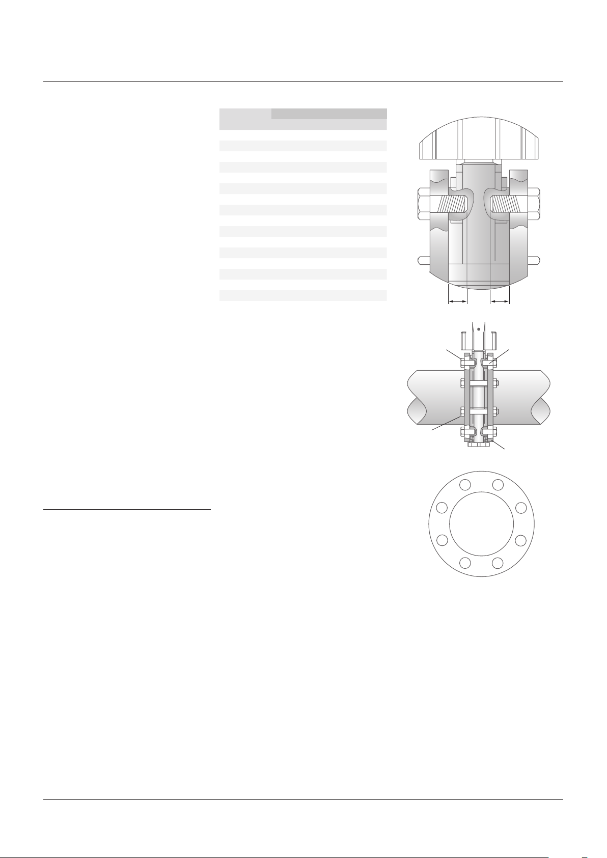
FLANGE BOLTS
CAUTION
It is critical that flange bolts do not bottom out in
the valve body tapped holes, as this could cause
damage to the valve chest area. Stud bolts can be
used in blind holes to alleviate the risk of flange
bolts bottoming out.
BODY FLANGE TAPPING DEPTH
Valve size Dimensions 'R'
DN (NPS) mm inches
50 (2) 12 ½
65 (2½) 12 ½
80 (3) 12 ½
100 (4) 12 ½
125 (5) 15
150 (6) 15
200 (8) 18 ¾
250 (10) 12 ½
300 (12) 16 ⅝
350 (14) 16 ⅝
400 (16) 22 ⅞
450 (18) 35 1⅜
500 (20) 32 1¼
600 (24) 30 1⅛
700 (28) 27 1
750 (30) 32 1¼
FIGURE 1
9
/
16
9
/
16
Flange
Flange
Valve
1
/
16
R
R
Blind holes
Bolt
in chest area
Bolts for
waferflanges
1
8
6
4
Pipe flange
3
5
7
2
To determine the bolt length for the blind holes
in the flange bolting , add the width of the mating
flange, + any washers to dimension 'R'.
Coating the flange bolt threads with an anti-seize
compound (e.g. Loctite 729) is recommended to
prevent bolt seizure.
2

CLARKSON KNIFE GATE VALVES
FIGURE 955/956
FLUSHING PORTS
CAUTION
Valves should be isolated prior to flushing, as valve
operation during flushing,
cause the discharge of pipeline media through the
flushing ports at full pipeline pressure.
Valves are provided with flushing ports
to enable the valve body to be cleared of
sedimentation or debris which could impair
valve operation. The provision of a suitable
flushing system to each valve is imperative to
assure proper valve operation.
The type of flushing system employed will need
to be decided by site/project personnel with
due regard to such factors as, services
available, pipeline media, solids content,
service duty, and individual site considerations.
Please contact our Emerson sales/engineering
centres for recommendations on suitable
systems.
NOTE
It should be noted that the use of 'positive flushing' is
mandatory for valves used for line media’s containing
hard gravel like solids.
Manual flushing
With the valve in either the open or closed
position, the flushing port plugs may be
carefully removed (see caution note above).
Apply a strong pressurized stream of fluid to
each port
the opposing port. When body is cleared, refit
port plugs.
Waste flushing
Flushing plugs may be removed from the
ports and permanent pipework installed to
each port to direct pipeline media, lost during
valve cycling, to a collection point or to waste.
Additional valving may be installed in this
pipework to limit the velocity and/or duration
ofthe media discharge.
allowing the discharge of debris from
or defective seats, may
Positive flushing
Pipework may be attached to the flushing
ports to supply the lower valve body with line
compatible fluid at a pressure significantly
above that of the pipeline.The flushing
supply system must also be capable of a
volumetric delivery suitable for this application.
Theflowofflushing media into the main
pipeline during valve actuation both minimizes
the amount of debris and sedimentation in the
lower bucket, and also clears larger pipeline
solids from the seat area for valve re-opening.
Someperiodic flushing of the lower bucket will
still berequired to clear sedimentary solids.
Automatic flushing
Additional valving and pipework may be
installed to the flushing ports to supply flushing
media to one of the flushing ports and a drain
facility to the other. The flushing system may
then be activated by a control system during
valve cycling.
Gland adjustment
Gate gland adjustment on new or rebuilt valves
should be checked on valve installation to the
pressurized pipeline. If leakage occurs, tighten
each adjustment nut evenly until the leak
subsides. If leakage persists check that the
valve is not being subjected to line pressures
above that of its pressure rating, orthat
the packing may be damaged, incorrectly
installed or contaminated with foreign matter
(refergland packing instruction sheet).
CAUTION
Do NOT over tighten gland packing as this will
impede valve operation and cause premature
gate/packing wear.
3

Neither Emerson, Emerson Automation Solutions, nor any of their affiliated entities assumes responsibility for the selection, use or maintenance of any product.
Responsibility for proper selection, use, and maintenance of any product remains solely with the purchaser and end user.
Clarkson is a mark owned by one of the companies in the Emerson Automation Solutions business unit of Emerson Electric Co. Emerson Automation Solutions, Emerson
and the Emerson logo are trademarks and service marks of Emerson Electric Co. All other marks are the property of their respective owners.
The contents of this publication are presented for informational purposes only, and while every effort has been made to ensure their accuracy, they are not to be
construed as warranties or guarantees, express or implied, regarding the products or services described herein or their use or applicability. All sales are governed by
our terms and conditions, which are available upon request. We reserve the right to modify or improve the designs or specifications of such products at any time without
notice.
Emerson.com/FinalControl
 Loading...