

Page 1
@
Installation, Operation, & Maintenance Instructions
R500.E245A
03/04/2016
®
Simpliport 180
16633 Foltz Parkway Ɣ Strongsville, OH 44149 USA Telephone: +1 (440) 572-1500 Ɣ Fax: +1 (440) 238-8828
www.clark-reliance.com Ɣ sales
clark-reliance.com
Page 2

@
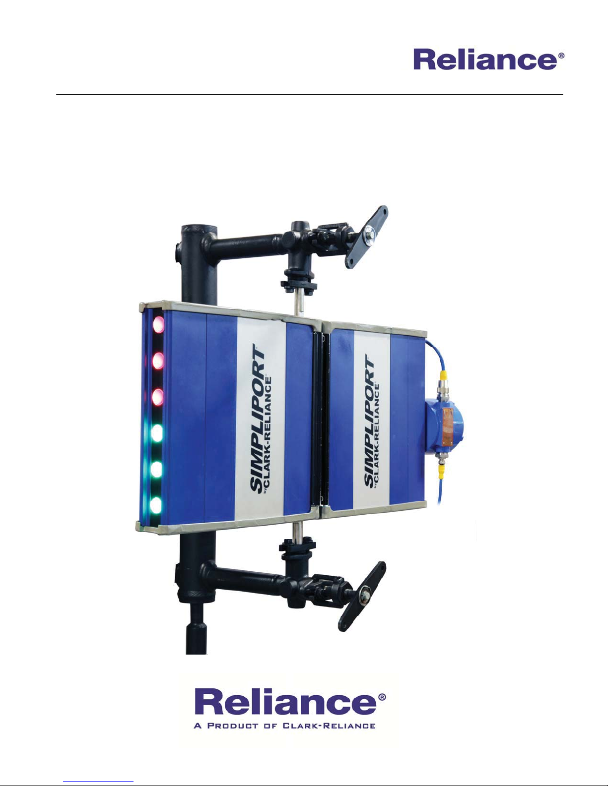
The Reliance®Simpliport® 180 LED Illuminator
has been designed to accept 120VAC or 240 VAC
power sources and for a service life of up to 7 years.
The LED Illuminators are weatherproof and are
rated safe for use in ordinary locations
Note: All installation steps should be performed
by a qualified technician and should be executed
in accordance with all applicable national and
local codes.
STORAGE and HANDLING
All units should be inspected upon receipt to ensure
that no damage has been incurred during transit. If
there is a claim due to damage, it should be filed
with the carrier immediately. Units should be stored
in a dry and sheltered area prior to installation, in a
secure manner where they can neither fall, nor be
struck by other objects. The temperature of the
storage area should not exceed 170q F. (75q C.)
COMPONENTS
There are five main components that make up the
Simpliport Illuminator Assembly: the LED
Illuminator, the front end hood, the mounting bar
assembly, the power supply, and the cable
connecting the power supply to the LED
Illuminator. The cable may have more than one
piece depending on the required distance between
the Illuminator and the power supply. In most cases,
however, the power supply will be mounted directly
to the LED Illuminator.
INSTALLATION
The LED Illuminator and power supply should
be checked to ensure that they contain no foreign
matter, and that the end connections are clean,
undamaged, and in line with existing conduit.
Step by step instructions:
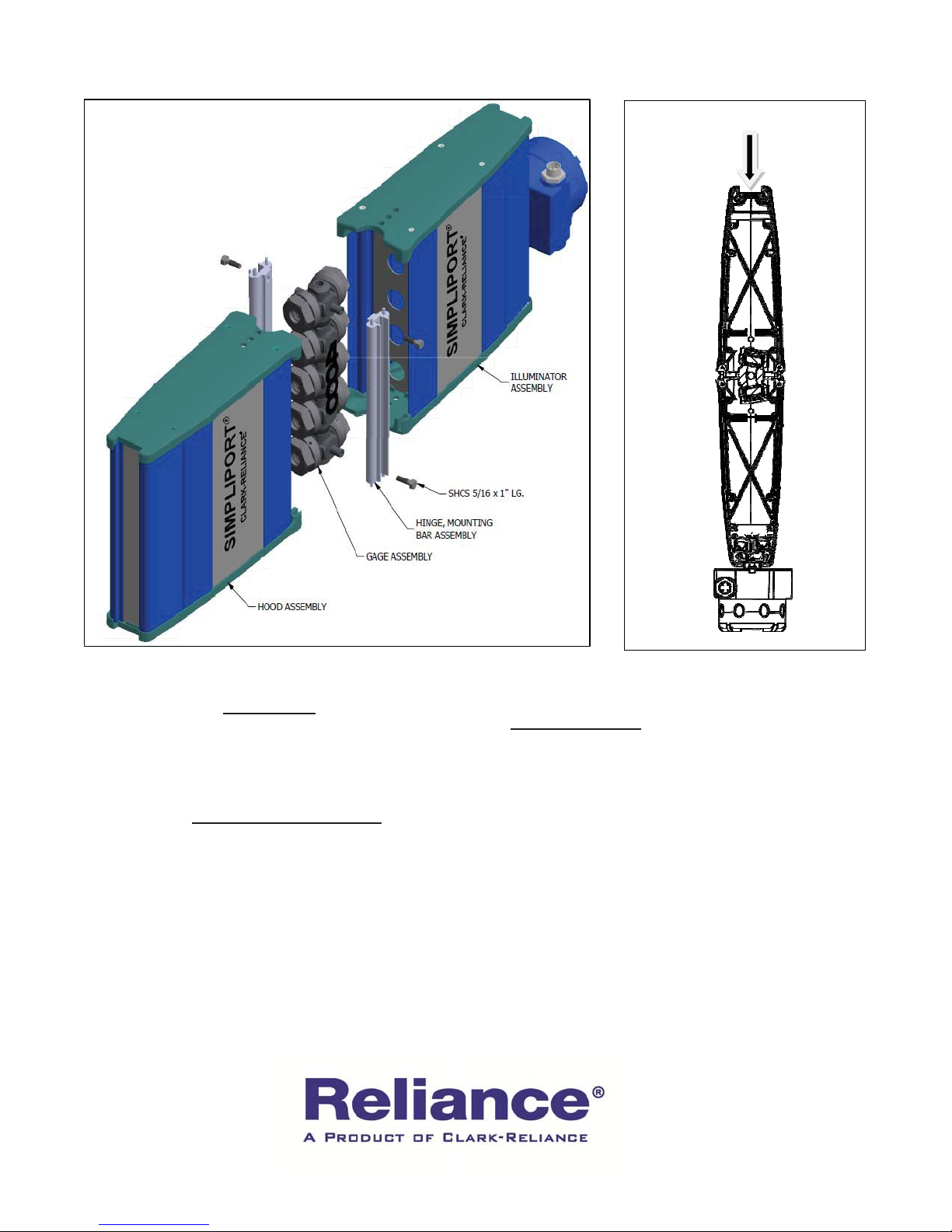
1) Assemble the mounting bar assemblies to the
Simpliport Gage mounting lugs using the (4)
5/16” X 1” SHCS that are provided (Fig. 1).
2) To mount the LED Illuminator assembly to
the gage: While holding the illuminator at a
slight angle, slide illuminator top onto pins.
Align bottom pins with slots and rest unit in
place. Note: The Simpliport
®
Gage must be
viewed with the packing nuts facing
slightly to the left. Make sure the
Illuminator and viewing hood are in the
correct orientation to the Simpliport
®
Gage. (Fig. 2)
3) Repeat the procedure in Step 2 to mount the
front end hood to the opposite side (viewing
side) of the gage.
CAUTION: All LED Illuminators are
tagged with the service conditions for that
particular unit. This information is located on
the power supply housing. The ratings should be
reviewed prior to installation and again prior to
start-up, to ensure proper operation in the
installed environment.
IMPORTANT
Never remove the blue cord between the power
supply and illuminator while power is applied.
Doing so will cause permanent damage to the
LEDs.
16633 Foltz Parkway Ɣ Strongsville, OH 44149 USA Telephone: +1 (440) 572-1500 Ɣ Fax: +1 (440) 238-8828
www.clark-reliance.com Ɣ sales
4) The unit’s power supply has wire leads and a
fuse ready to connect to the incoming AC
power source. Remove the enclosure lid to
access wiring. Connect incoming AC power
source per local and National Electric Codes.
The fused (red) wire is to be connected is the
“Hot” and the remaining white wire is the
“common”.
5) The power supply can be remote mounted if
desired. After remote mounting of power
supply, if the blue power cord will not reach
the power supply, contact your local
representative.
clark-reliance.com
Page 3
@
Typical Installation
OPERATION
The Simpliport® 180 LED Illuminator can operate
continuously. The operating life of the LED’s is up to
7 years under normal conditions.
ROUTINE MAINTENANCE
Keep glass on the front of the front end hood and in
the illuminator assembly clean using commercial
glass cleaners, such as Windex
use harsh abrasives, wire brushes, metal scrapers, or
any material that could scratch the glass.
The Illuminator and viewing hood may be removed
while in operation to inspect the Simpliport
Figure 1 Figure 2
®
or similar. Never
®
Gauge.
Viewing the Gauge
SPECIFICATIONS
Power Supply: 115/230 VAC @ 50-60 Hz
Max Power
Consumption: 500 mA
Est. Life: Up to 7 years (continuous)
Agency Approvals: FM/CFM Ordinary Locations
Wire Size: Min 16 AWG / Max 10 AWG
Max dist. from
power supply to light: 72’ (22 M)
Standard Cable = 8’ (2.5M)
Ambient Temperature: -40 F (-40 C) to 170 F (77C)
16633 Foltz Parkway Ɣ Strongsville, OH 44149 USA Telephone: +1 (440) 572-1500 Ɣ Fax: +1 (440) 238-8828
www.clark-reliance.com Ɣ sales
clark-reliance.com
Page 4

16633 Foltz Parkway Ɣ Strongsville, OH 44149 USA Telephone: +1 (440) 572-1500 Ɣ Fax: +1 (440) 238-8828
@
www.clark-reliance.com Ɣ sales
clark-reliance.com
Page 5
Installation, Operation, & Maintenance Instructions
R500.E245A-Supplement
08/31/2016
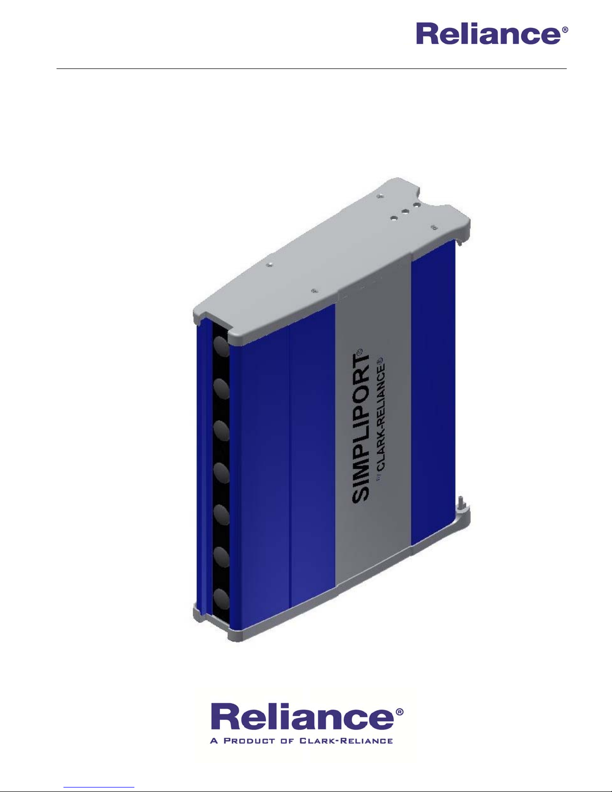
Removing Simpliport® 180 Optic Outputs for Outdoor
Viewing in Direct Sunlight
®
16633 Foltz Parkway ● Strongsville, OH 44149 USA Telephone: +1 (440) 572-1500 ● Fax: +1 (440) 238-8828
Page 6
When the Simpliport® 180 System is mounted in direct sunlight, the optic signal may be
difficult to read or completely washed out by the intensity of the sunlight. Perform the
following steps to improve the viewing of the water level in the gage glass. Note that the wide
angle feature of the Simpliport 180 will no longer be available and the observer must look
directly (horizontally) into the front hood to see the water level.
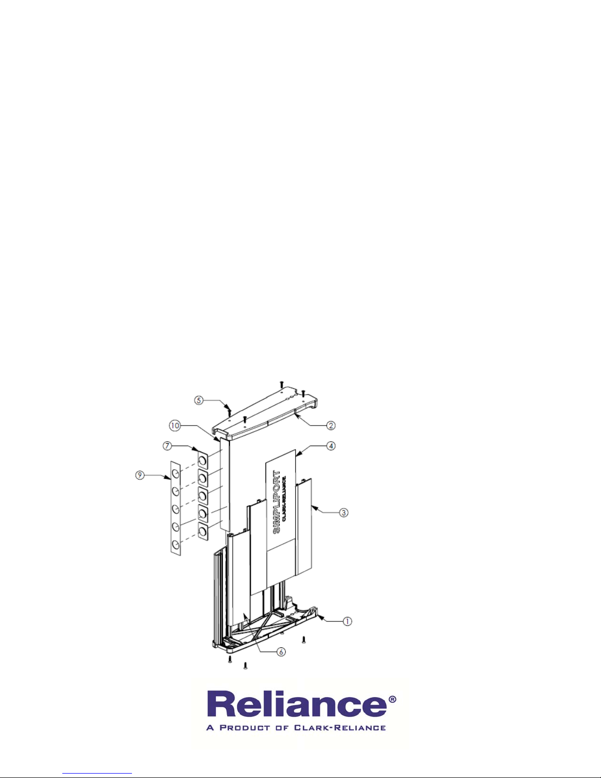
1. Using a Phillips screwdriver, remove the four screws (Item #5) from the Top End Cap (Item
#2) and remove the cap.
2. Carefully slide out the Glass Shield (Item #10), the Optic Outputs (Item #7), and the Optic
Output Plate (Item #9). Note: Black rubber spacer (not shown in detail below) on the bottom
end cap under the Glass Shield must remain in place.
3. Set the Optic Outputs aside.
4. Insert the Glass Shield and Optic Output Plate back into the glass track in the Viewing Hood
Extrusion (Item #6) with the Plate going in front of the Glass as shown in the illustration below.
5. Replace the Top End Cap, aligning the screw holes in the Cap with corresponding screw
holes in the Side Panels (Item #3) and the Viewing Hood Extrusion.
6. Replace the four screws and tighten.
7. The conversion is now complete and the Front Hood can be installed back on to the
Simpliport Gage Glass.
16633 Foltz Parkway ● Strongsville, OH 44149 USA Telephone: +1 (440) 572-1500 ● Fax: +1 (440) 238-8828
Page 7

@
Notes:
16633 Foltz Parkway Ɣ Strongsville, OH 44149 USA Telephone: +1 (440) 572-1500 Ɣ Fax: +1 (440) 238-8828
www.clark-reliance.com Ɣ sales
clark-reliance.com
Page 8

16633 Foltz Parkway Ɣ Strongsville, OH 44149 USA Telephone: +1 (440) 572-1500 Ɣ Fax: +1 (440) 238-8828
@
www.clark-reliance.com Ɣ sales
clark-reliance.com
 Loading...