

Page 1
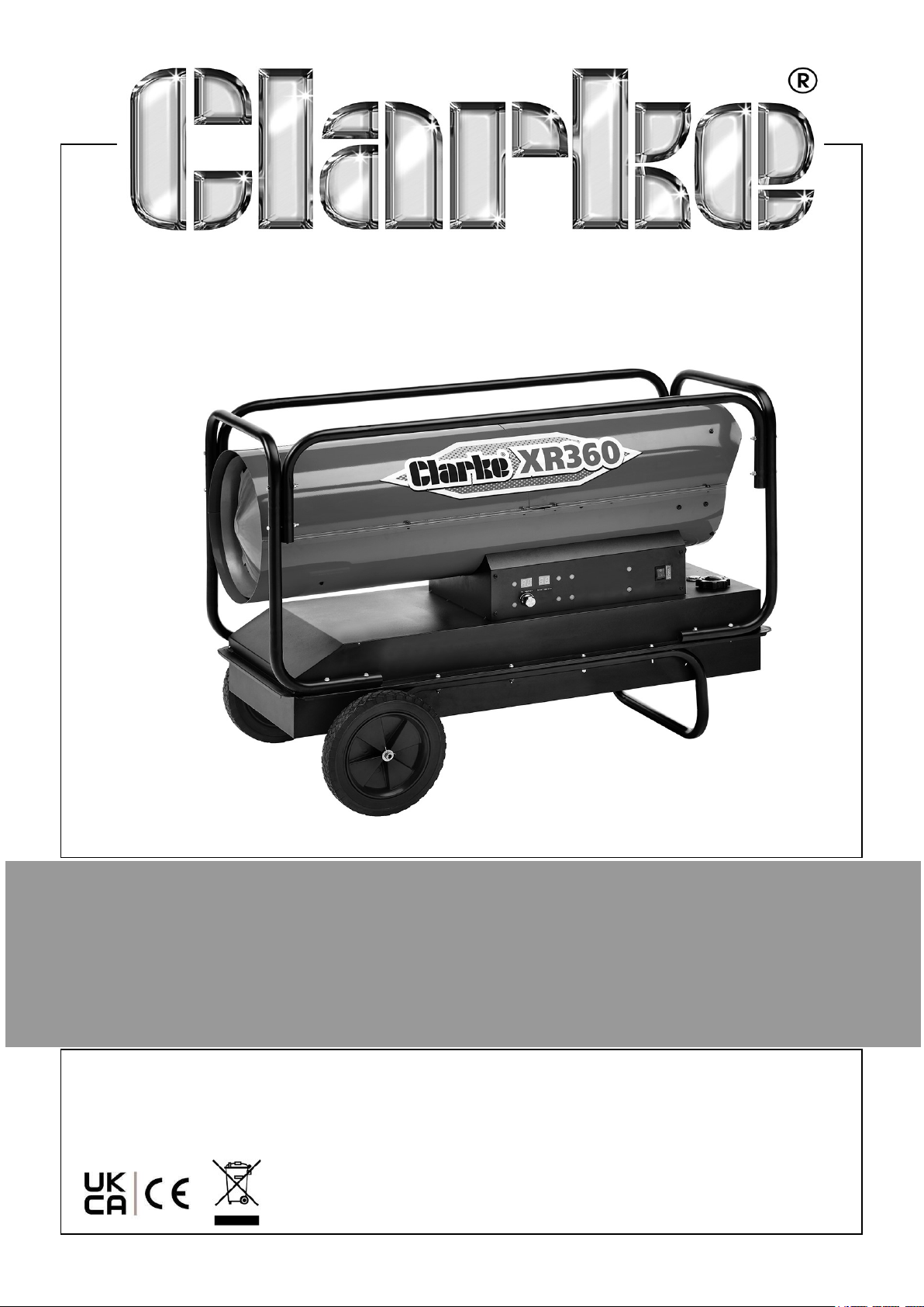
DIESEL/PARAFFIN HEATER
MODEL NO: XR360
PART NO: 6920199
OPERATION & MAINTENANCE
INSTRUCTIONS
ORIGINAL INSTRUCTIONS
GC06/25
Page 2
INTRODUCTION
Thank you for purchasing this CLARKE product.
Before attempting to use this product, please read this manual thoroughly and follow
the instructions carefully.
This is a forced air unit, where a fan pushes the air through the heater body. Proper
combustion depends upon this air flow; therefore, the heater must not be modified or
operated with parts removed or missing. Likewise, safety systems must not be
circumvented or modified in order to operate the heater.
GUARANTEE
This product is guaranteed against faulty manufacture for a period of 12 months from
the date of purchase. Please keep your receipt which will be required as proof of
purchase. This guarantee is invalid if the product is found to have been abused or
tampered with in any way, or not used for the purpose for which it was intended.
Faulty goods should be returned to their place of purchase, no product can be
returned to us without prior permission.
This guarantee does not effect your statutory rights.
FUNCTION AND OPERATING PARAMETERS
This is a multi-fuel (Diesel or Paraffin), forced air heater. It’s intended use is for drying
and the warming of commercial/industrial buildings where adequate ventilation is
provided.
• It must be operated as prescribed in the operating manual.
• It is not intended to be used for domestic use or for the heating of habitable
areas.
• It is not intended to be used to reach and maintain a certain level of human
thermal comfort within an enclosed space in which the heater is situated.
• It is not intended to be used in enclosed areas with restricted ventilation.
• It is not for use in areas with high levels of fluctuating drafts.
• The heater must be placed on a flat level non combustible surface during
operation.
• It is not intended for warming animals or live stock.
2
Parts & Service: 020 8988 7400 / E-mail: [email protected] or [email protected]
Page 3

SAFETY WARNINGS
CAUTION: DUE TO THE HIGH SURFACE AND EXHAUST
TEMPERATURES, ADULTS, CHILDREN AND ANIMALS MUST KEEP
CLEAR OF THE UNIT TO AVOID BURNS OR CLOTHING IGNITION.
Your safety is important to you and to others, so please read these
instructions before you operate this heater.
1. Failure to comply with the precautions and instructions provided with this heater
can result in death, serious bodily injury and property loss or damage from the
hazards of fire, explosion, burns, asphyxiation, carbon monoxide poisoning, and/
or electric shock.
2. Only persons who understand and follow the instructions should use or service
this heater.
3. When used, the heater should rest on a non-combustible floor at least 1” thick
and extending 3 feet or more beyond the heater in all directions.
4. NOT for home or recreational vehicle use.
5. DO NOT use petrol or other volatile fuels.
6. Disconnect the heater from the power supply before adding fuel.
7. ALWAYS re-fuel outdoors away from any open flame or other sources of ignition.
8. DO NOT use an external fuel source.
9. DO NOT use the heater where flammable liquids or vapours may be present.
10. DO NOT start the heater when the combustion chamber is hot.
11. Plug the electrical cable into a properly grounded mains socket.
12. DO NOT leave the heater unattended when in use.
13. DO NOT start or use the heater if there is unburned fuel in the combustion
chamber.
14. DO NOT use if dropped.
15. Check the heater thoroughly for damage. NEVER operate a damaged heater.
16. This heater is for indoor use only.
17. DO NOT use this heater in the immediate surrounds of a bath, a shower or a
swimming pool.
18. DO NOT use this heater in small rooms when they are occupied by persons not
capable of leaving the room on their own unless constant supervision is provided.
3
Parts & Service: 020 8988 7400 / E-mail: [email protected] or [email protected]
Page 4
19. Use in well ventilated spaces and provide at least 3 sq. ft. (0.28 sq.m) of air
opening of outside air for every 100,000 Btu/hr (30kW) heater rating.
20. ALWAYS keep combustibles, like textiles, paper and wood at least 3m from the
front of the heater and 1.5 m from the top, sides and rear.
21. Locate the heater 10 ft. (3 m) from canvas or plastic coverings and secure them to
prevent movement.
22. Make sure that the heater is not directly exposed to rain or water spray.
23. NEVER use in living spaces and/or where children may be present.
24. DO NOT use with ductwork. DO NOT restrict air inlet or exit.
25. DO NOT move or service the heater while hot or in operation.
26. Use only in accordance with local regulations and relevant building codes.
27. This heater is only intended for use in industrial, commercial and building
industries, it is NOT to be used by children or persons with reduced physical,
sensory or mental capabilities, or lack of experience and knowledge.
28. If the supply cable is damaged, it must be replaced by the manufacturer, its
service agent, or similarly qualified persons in order to avoid a hazard.
29. DO NOT use this heater with a programmer, timer, separate remote control
system or any other device that switches the heater on automatically, since a fire
risk exists if the heater is covered or positioned incorrectly.
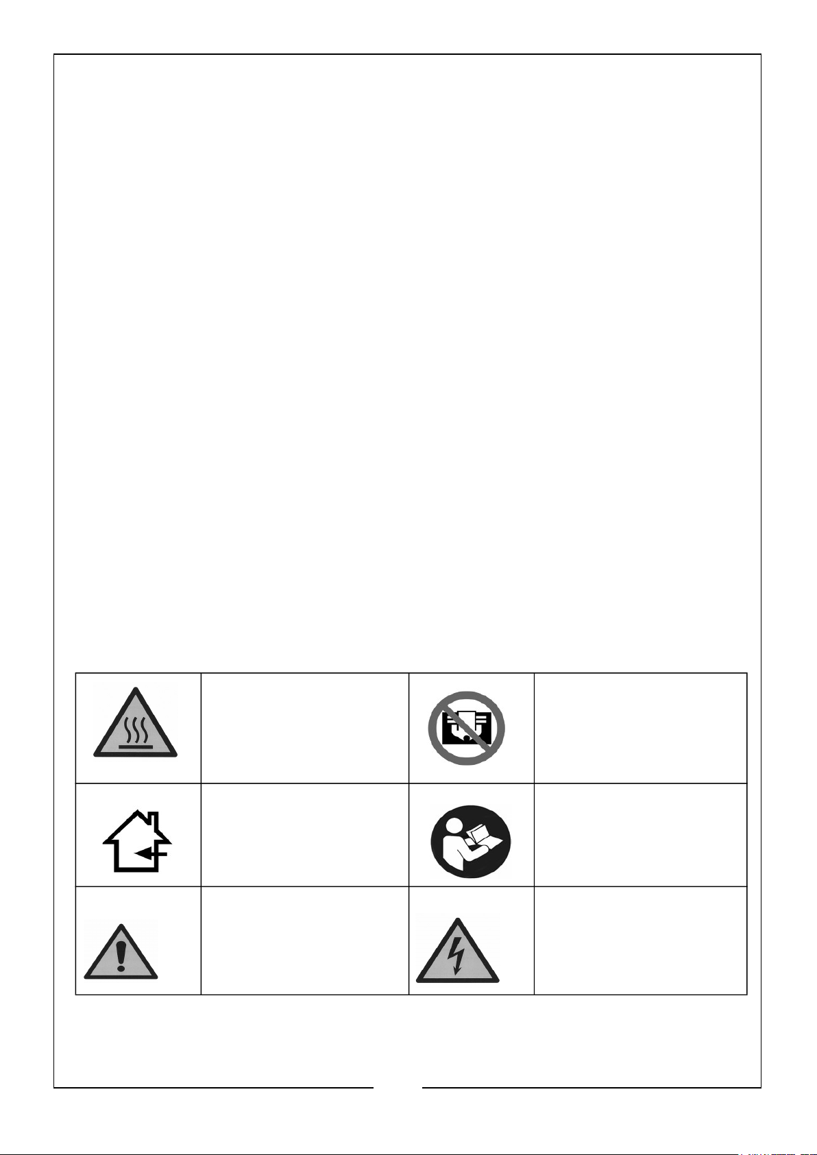
SAFETY SYMBOLS
The following symbols appear on the heater.
HOT SURFACE, DO
NOT TOUCH
INDOOR USE ONLY ALWAYS READ THE
GENERAL WARNING
HAZARD
DO NOT COVER
MANUAL
DANGER OF ELECTRIC
SHOCK
4
Parts & Service: 020 8988 7400 / E-mail: [email protected] or [email protected]
Page 5
GENERAL PRECAUTIONS
VENTILATION
Even though this heater operates very close to 100 percent combustion efficiency, it
still produces small amounts of carbon monoxide.
• Carbon Monoxide (CO) is toxic.
• Pregnant women, persons with a heart or lung condition, anaemia or
under the influence of alcohol, or those at high altitude, are more likely to
be effected by Carbon Monoxide.
• CO can build up in a confined space and failure to provide adequate
ventilation can be fatal.
The early symptoms of asphyxiation caused by inadequate ventilation are:
• headache • nausea
• dizziness • dry mouth or sore throat
Should anyone show these symptoms, they must GET FRESH AIR IMMEDIATELY.
Turn off the heater and have it serviced before using again.
Be sure to follow all warnings in this manual.
WE RECOMMEND THE USE OF A CARBON
MONOXIDE DETECTOR
BYSTANDERS
When the heater is to be operated in the presence of other people the user is
responsible for informing those present of the safety precautions and of the hazards
involved.
ENVIRONMENTAL RECYCLING POLICY
Through purchase of this product, the customer is taking on the obligation
to deal with the WEEE in accordance with the WEEE regulations in relation
to the treatment, recycling & recovery and environmentally sound disposal
of the WEEE.
In effect, this means that this product must not be disposed of with general
household waste. It must be disposed of according to the laws governing Waste
Electrical and Electronic Equipment (WEEE) at a recognised disposal facility.
5
Parts & Service: 020 8988 7400 / E-mail: [email protected] or [email protected]
Page 6
ELECTRICAL CONNECTIONS
WARNING: READ THESE ELECTRICAL SAFETY INSTRUCTIONS
THOROUGHLY BEFORE CONNECTING THE PRODUCT TO THE
MAINS SUPPLY.
Connect the mains lead to a standard, 230 Volt (50Hz) electrical supply through an
approved BS1363/A plug fitted with a BS1362 7 amp fuse.
If the plug has to be changed because of damage, it must be removed and a
replacement fitted, following the wiring instructions shown below. The old plug must
be discarded safely, as insertion into a power socket could cause an electrical hazard.
WARNING: WIRES IN THE MAINS LEAD ARE COLOURED IN
ACCORDANCE WITH THE FOLLOWING CODE:
GREEN/YELLOW = EARTH, BLUE = NEUTRAL, BROWN = LIVE.
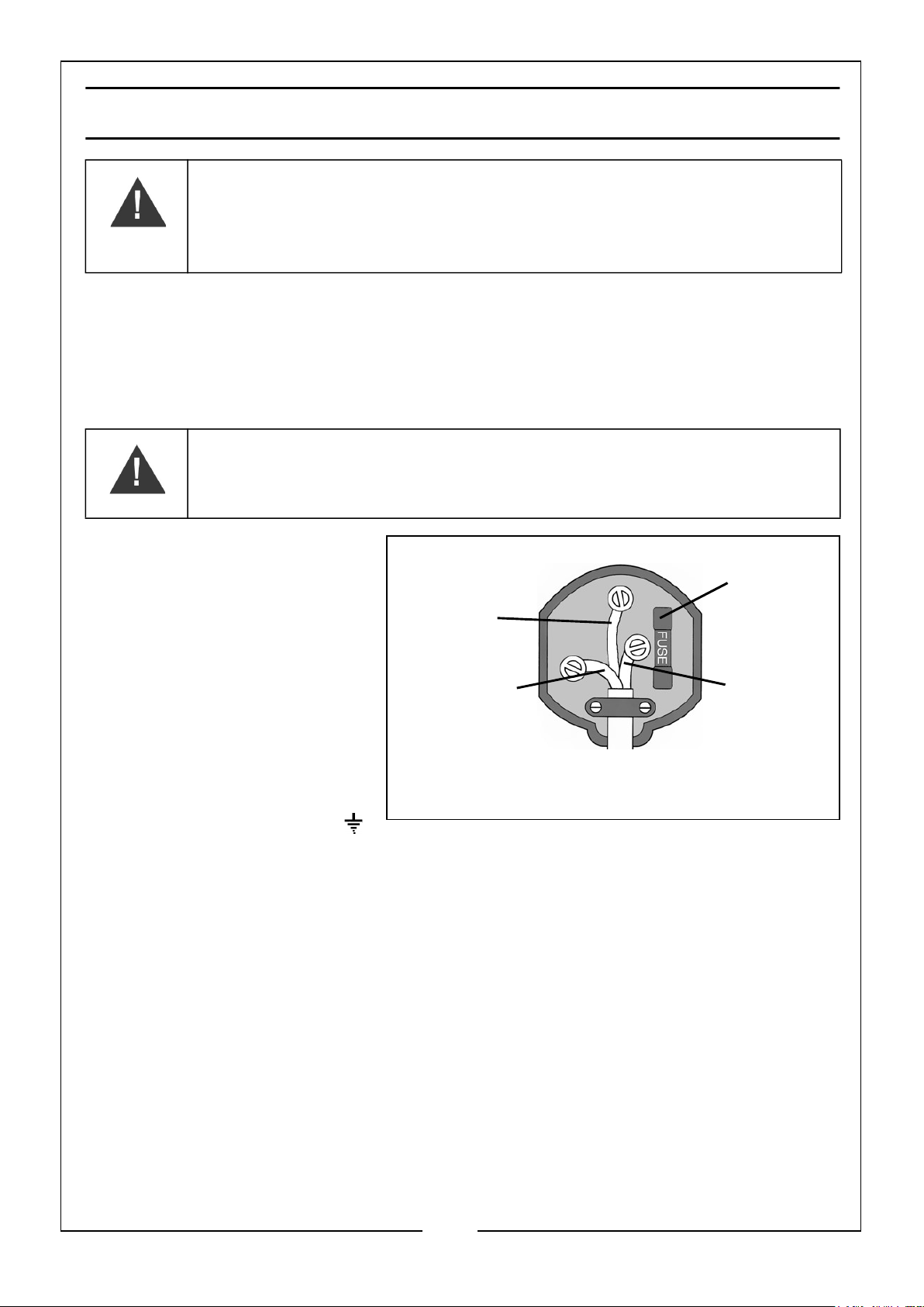
• The BLUE wire must be
connected to the
terminal marked N or
coloured black.
• The BROWN wire must
be connected to the
terminal marked L or
coloured red.
• The YELLOW AND
GREEN wire must be
connected to the
terminal marked E or
or coloured green.
We strongly recommend that this machine is connected to the mains
supply through a Residual Current Device (RCD)
If you are not sure, consult a qualified electrician. DO NOT try to do any
repairs.
(Green and
Yellow)
Plug must be BS1363/A approved.
Earth
Neutral
(Blue)
Ensure that the outer sheath of
the cable is firmly held by the clamp
Always fit
a 7 Amp
fuse.
Live
(Brown)
6
Parts & Service: 020 8988 7400 / E-mail: [email protected] or [email protected]
Page 7
PREPARATION
Remove heater from crate and remove all protective material which may have been
applied to the heater for shipment.
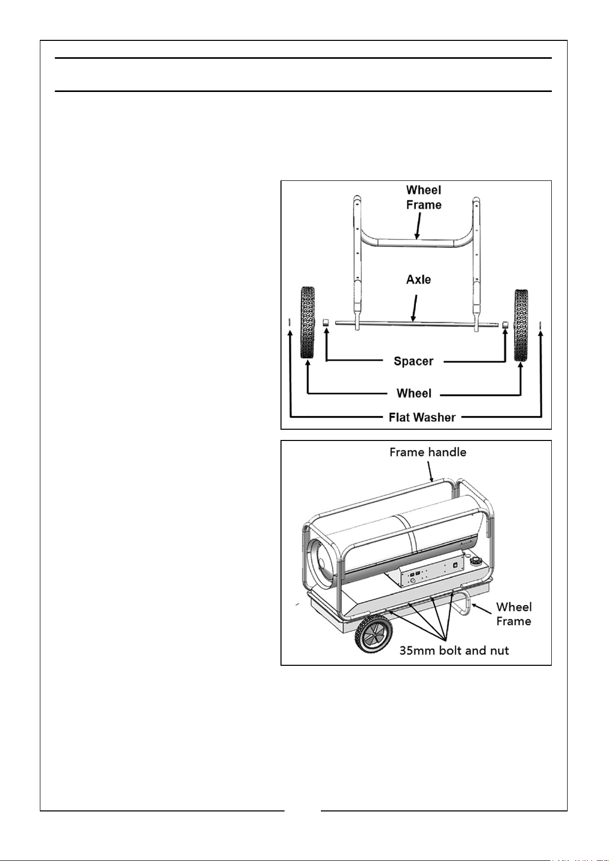
ASSEMBLY
1. Pass the axle through the wheel
frame as shown.
2. Fit a spacer onto each end.
3. Fit a wheel on to each end.
4. Fit a flat washer onto each end.
5. Secure in place by inserting a
split-pin into the hole at the end
of the axle.
6. Place the assembly into position
and secure using four 35 mm
bolts and nuts provided (2 each
side).
FUEL TYPES
Diesel or paraffin are the only fuels
that should be used in this heater.
FILLING THE FUEL TANK
IMPORTANT: Before filling the
fuel tank the first time or after
extended storage periods,
drain the fuel tank of any
moisture or condensation.
1. Follow all of the “Safety Warnings” on pages 3-4 of this manual.
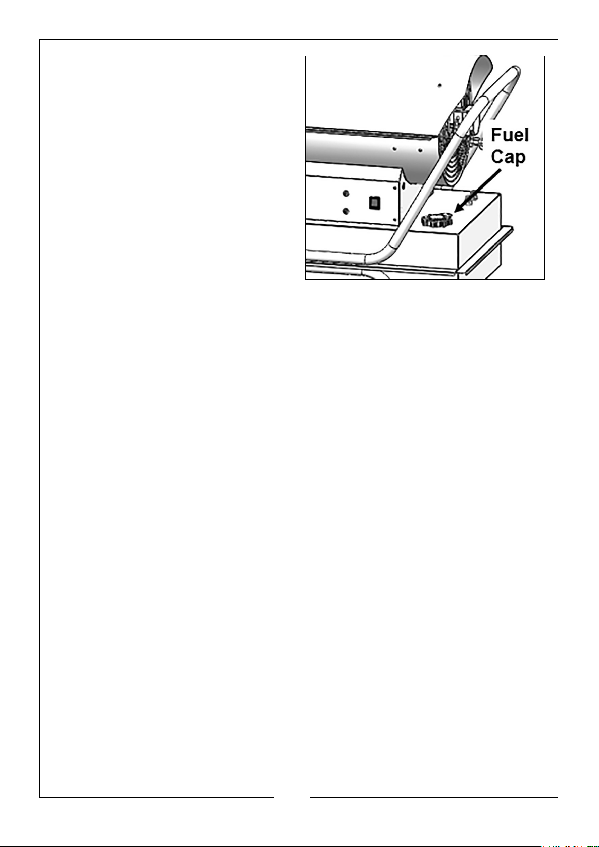
2. Remove the fuel cap.
NOTE: If you lose the fuel cap a replacement must be obtained before use. This is
available from your local CLARKE service department.
7
Parts & Service: 020 8988 7400 / E-mail: [email protected] or [email protected]
Page 8
3. Fill the fuel tank with clean diesel or
paraffin.
• In cold weather, condensation may
develop in the tank if the tank is
empty and it is recommended that
a tablespoon of de-icer be added
for each gallon of fuel in the tank.
• When filling the heater, make sure
that the heater is level and do not
overfill. Use a funnel or can with a
long fill spout.
• Fill with a minimum of 19
litres of fuel at all times to
avoid fuel starvation if the
supply is exhausted.
• ALWAYS clean up any fuel spillages before starting the heater.
HEATER LOCATION
• Locate heater at a safe distance from combustible materials.
• When used, the heater should rest on suitable non-combustible floor
extending 3 ft or more beyond the heater in all directions.
• Only operate on a flat level and stable surface.
8
Parts & Service: 020 8988 7400 / E-mail: [email protected] or [email protected]
Page 9
OPERATION
START UP
WARNING: DO NOT START THE HEATER WHEN EXCESS FUEL HAS
ACCUMULATED IN THE COMBUSTION CHAMBER.
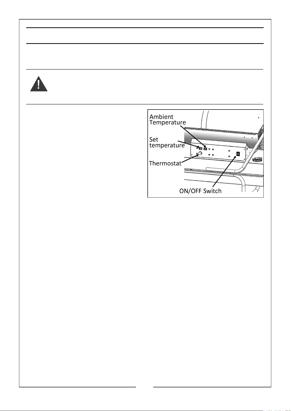
1. Make sure power switch is in the OFF
position.
2. Plug the heater into the mains power
supply.
3. Start heater by setting the power
switch to the ON position.
4. Turn the thermostat control knob to
the desired temperature as shown on
the display. After waiting for several
seconds, the heater starts.
SHUT DOWN
1. Set the power switch to the OFF position.
2. For extended shut-down unplug the heater from the mains supply.
• DO NOT disconnect the heater from mains to stop it while in operation.
Always allow the cooling sequence to be completed, otherwise the residual
heat could damage internal components.
BEFORE STORAGE
• Clean the heater as described in the MAINTENANCE section on page 10.
9
Parts & Service: 020 8988 7400 / E-mail: [email protected] or [email protected]
Page 10
MAINTENANCE
WARNING: TO PREVENT PERSONAL INJURY, UNPLUG THE HEATER
FROM THE MAINS SUPPLY BEFORE SERVICING
WARNING: BEFORE STARTING ANY MAINTENANCE TASK, SHUT
DOWN, UNPLUG AND LET THE HEATER COOL DOWN FOR AT LEAST
15 MINUTES.
DAILY CHECKS
1. Make a general visual inspection of the heater for loose or damaged parts.
2. Damaged parts should be repaired or replaced before using the heater again.
3. Check heater operation to be sure it is operating normally as follows:
• The flame is contained within the heater.
• The flame is essentially yellow.
• There is no disagreeable odour, eye burning or other physical discomfort.
• There is no smoke or soot internal or external to the heater.
GENERAL
• Regularly wipe the cover using a soft sponge or cloth. For very dirty parts,
use a sponge wetted with lukewarm water and a mild detergent, then dry
using a clean cloth.
• Keep air inlet and fan free from dust and dirt. To clean inner parts, gently
blow compressed air through air inlet. (Wear eye protection if using
compressed air).
• Regularly inspect the power cable. If worn, cracked or damaged have it
replaced by technical service.
• When cleaning, make sure that water does not enter the unit.
• DO NOT open the enclosure to clean the inner parts.
• Never use solvents, gasoline, toluene and similar aggressive chemicals to
clean the heater.
• Clean twice a season. Drain and flush the fuel tank with clean fuel.
NOTE: The following checks BY QUALIFIED PERSONNEL ONLY are recommended
before every seasonal use:
NOTE: DO NOT attempt any electrical repair yourself. If the heater needs service or
repair, contact a qualified technician or CLARKE service department.
10
Parts & Service: 020 8988 7400 / E-mail: [email protected] or [email protected]
Page 11
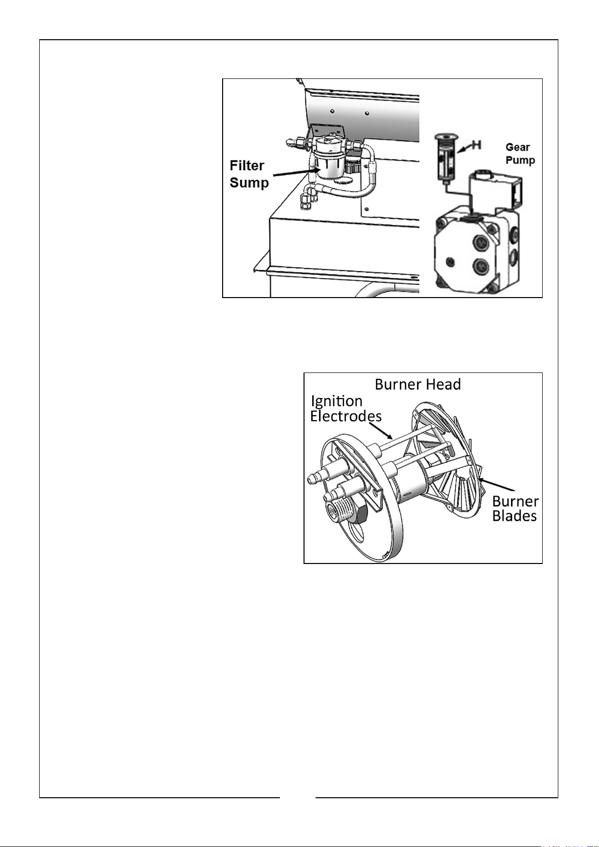
FUEL FILTERS
Clean fuel filters by
unscrewing the filter tray
anticlockwise.
Remove the filter cartridge
and wash it with petrol or
replace it if necessary.
Check the seal O-ring and
replace it if necessary.
Reassemble the sump.
The fuel filter installed on
the gear pump should be
cleaned or replaced if
necessary by unscrewing
cap H.
EXTRACT THE BURNER HEAD
BURNER BLADES
Clean the burner blades by using a brush
and then blowing compressed air onto
them. (Wear eye protection if using
compressed air). To get good
combustion, the air flow openings in the
whirl disc should be perfectly clear.
NOZZLE
Carefully unscrew the nozzle from the
nozzle fitting. Blow compressed air
through the nozzle orifice to free it from
dirt. (Wear eye protection if using
compressed air)
Replace the nozzle if necessary.
IGNITION ELECTRODES
Clean, adjust and if necessary replace the ignition electrode.
ELECTRICAL INSPECTION
Inspect cables, electrical parts and connections.
STORAGE
1. Drain any residual fuel / condensate from the fuel tank.
2. Before storing the heater, make sure it is perfectly cool and dry. Cover the unit
with a plastic bag, put it in its packing box and store it in a dry, ventilated place.
11
Parts & Service: 020 8988 7400 / E-mail: [email protected] or [email protected]
Page 12
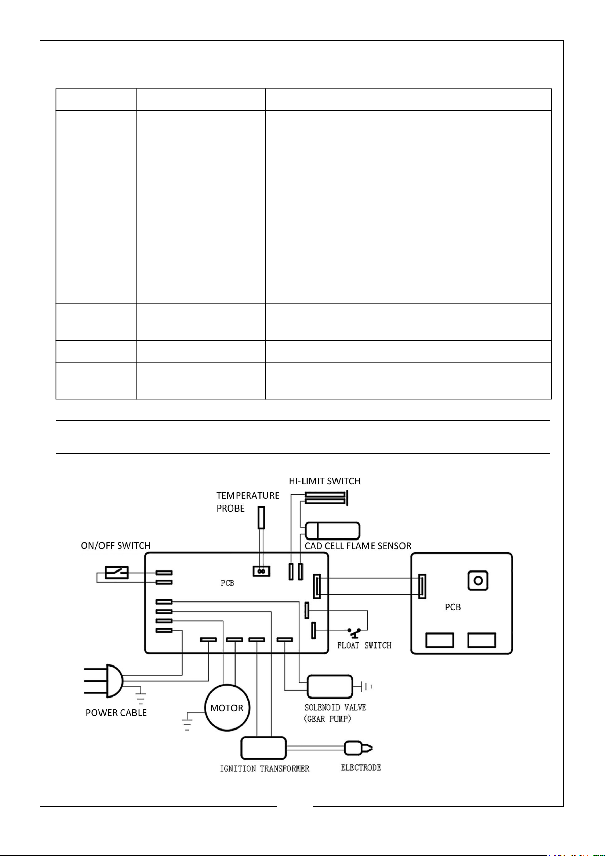
TROUBLESHOOTING
LED OPERATION TROUBLE SHOOTING
E1 1. No flame detected
2. High limit switch
failure (unit overheated)
E2 Temperature sensor
open or error
E3 Low fuel level Refuel heater
E4 Flame sensor
failure
1 Heater fails to start. Check fuel level and that
fuel cut-off switch is correctly set.
1.1 Check the mains plug is correctly fitted and
that the fuse inside if has not blown.
1.2 Restart
1.3 Return to supplier for service.
2. Make sure heater is cooled down,
2.1 Make sure that the power switch is set to the
OFF position.
2.2 Wait 5 minutes
2.3 Start heater by setting the power switch to
the ON position.
Check whether the temperature sensor is loose/
re-tighten connections
Return to CLARKE service department for repair.
WIRING DIAGRAM
12
Parts & Service: 020 8988 7400 / E-mail: [email protected] or [email protected]
Page 13
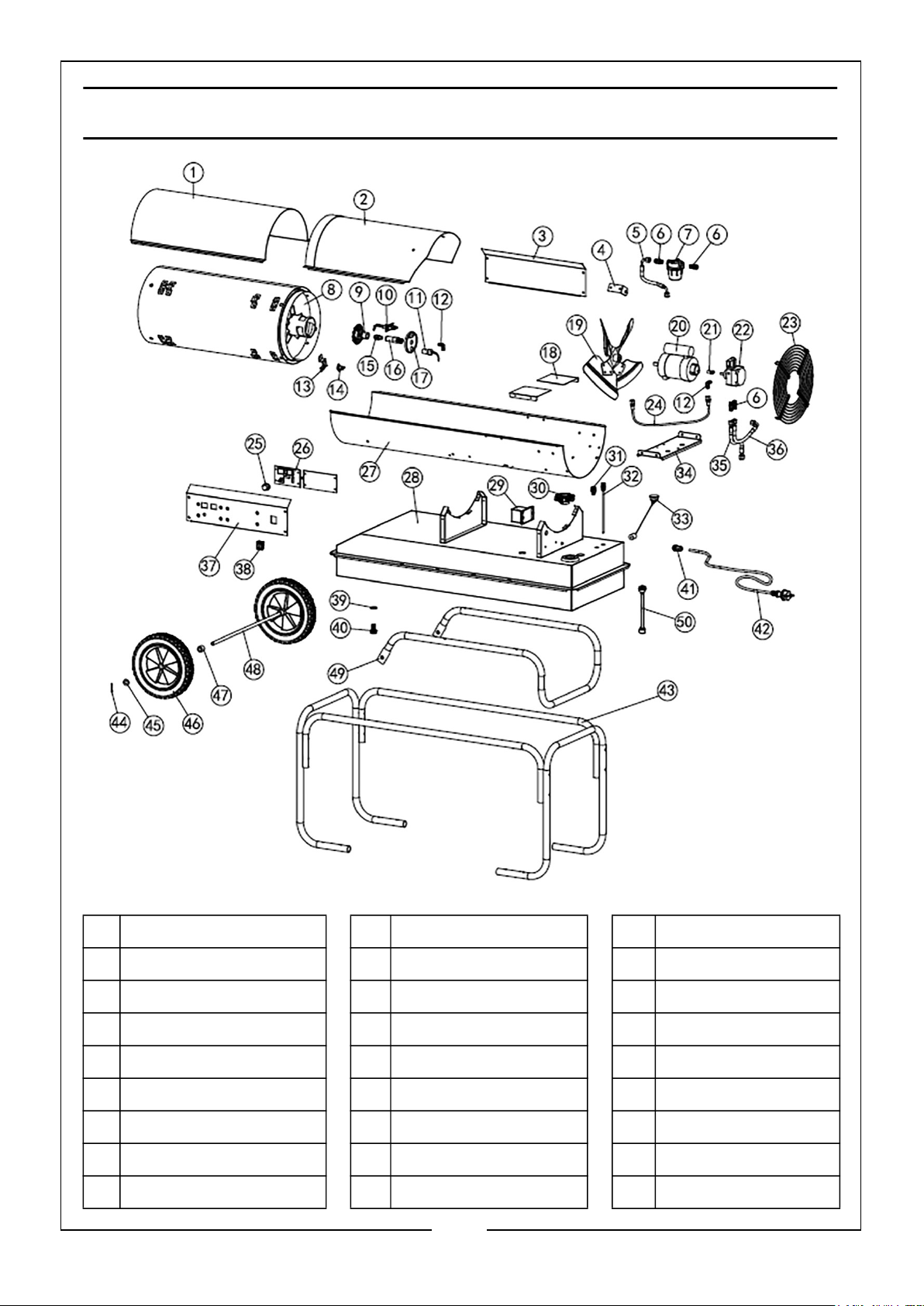
COMPONENT PARTS
1 Top shell-front 18 Air balance plate 35 Fuel pipe B
2 Top shell-rear 19 Fan 36 Fuel pipe C
3 Right panel 20 Motor 37 Left panel
4 Fuel filter support 21 Gear pump coupling 38 ON/Off switch
5 Fuel pipe A 22 Gear pump 39 Oil drain seal ring
6 Fuel filter joint 23 Fan guard 40 Oil drain screw
7 Fuel filter 24 High pressure pipe 41 Strain relief bush
8 Combustion chamber 25 Thermostat knob 42 Power cable
9 Swivel disc 26 Flame control 43 Handle
13
Parts & Service: 020 8988 7400 / E-mail: [email protected] or [email protected]
Page 14
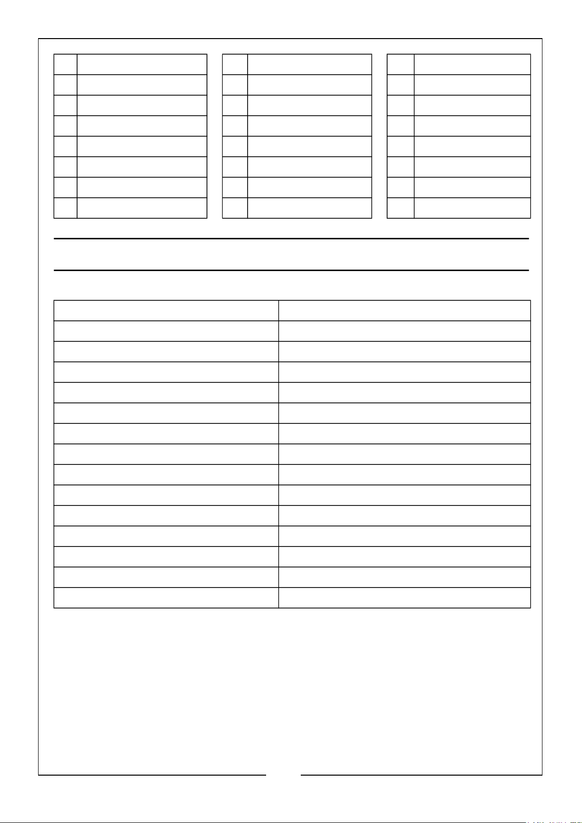
10 Ignition electrode 27 Bottom shell 44 Split pin
11 Cad cell flame sensor 28 Fuel tank 45 Flat washer
12 Elbow connection 29 Transformer 46 Wheel
13 Hi-limit switch support 30 Fuel cap 47 Spacer
14 Hi-limit switch 31 Fuel pipe joint 48 Axle
15 Nozzle 32 Fuel draw pipe 49 Frame
16 Nozzle support 33 Fuel gauge 50 Fuel level switch
17 Nozzle baseplate 34 Motor support
SPECIFICATIONS
Model XR360
Fuel type Diesel or paraffin
Burn Rate 105 kW
Fuel consumption: 9.8 L/hr
Approx Running Time: 7 hr
Pump pressure 15 bar
Electrical input: 230V ~ 50Hz
Heat Output 105 kW
Fuel Tank Capacity: 70 L
Ignition system: Electric Ignition
Primary Safety Controls Flame failure device & thermal cutout
Ingress Protection IPX0
Weight (kg) 46.5 kg
Dimensions (DxWxH)mm 1125 x 590 x 780 (wheels & handle fitted)
Minimum Fuel Level for startup 19 L
14
Parts & Service: 020 8988 7400 / E-mail: [email protected] or [email protected]
Page 15
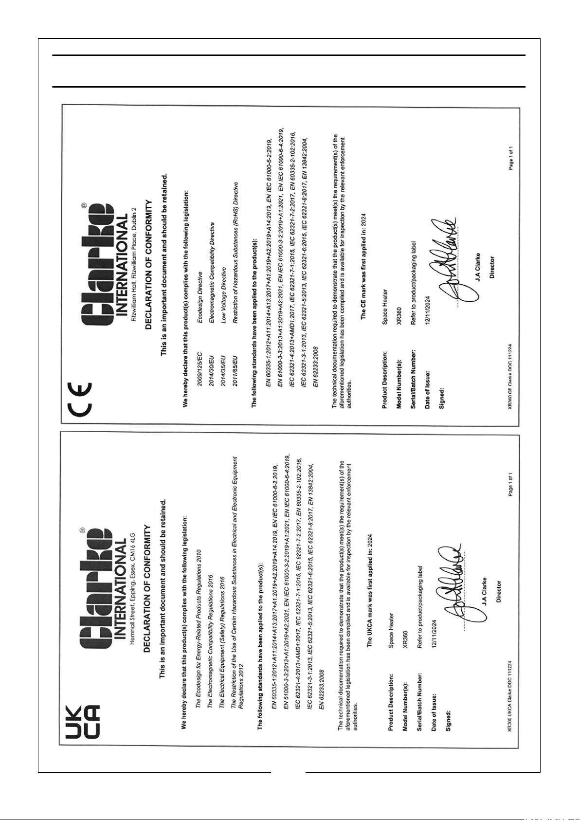
DECLARATIONS OF CONFORMITY
15
Parts & Service: 020 8988 7400 / E-mail: [email protected] or [email protected]
Page 16

 Loading...