

Page 1
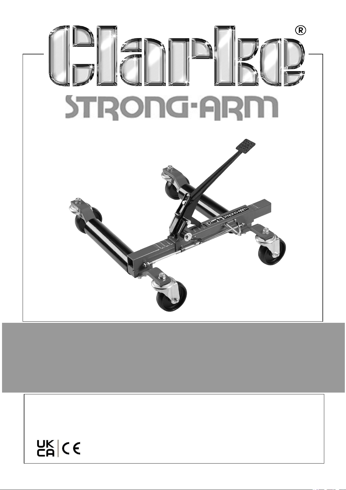
VEHICLE POSITIONING JACK
MODEL NO: VPJ300M
PART NO: 7624017
OPERATION AND MAINTENANCE
INSTRUCTIONS
ORIGINAL INSTRUCTIONS GC0925
Page 2
INTRODUCTION
Thank you for purchasing this CLARKE Vehicle Positioning Jack.
Before attempting to use this product, please read this manual thoroughly and follow
the instructions carefully. In doing so you will ensure the safety of yourself and that of
others around you and you can look forward to your purchase giving you long and
satisfactory service.
Keep these instructions for future reference.
SPECIFICATIONS
Dimensions (D x W x H) 620 x 570-730 x 400 mm
Weight 17.2 kg
Roller distance (min-max) 260 - 580 mm
Rated Load per wheel/jack 680 kg
Maximum rated weight 680 kg
Maximum tyre width 300 mm (12”)
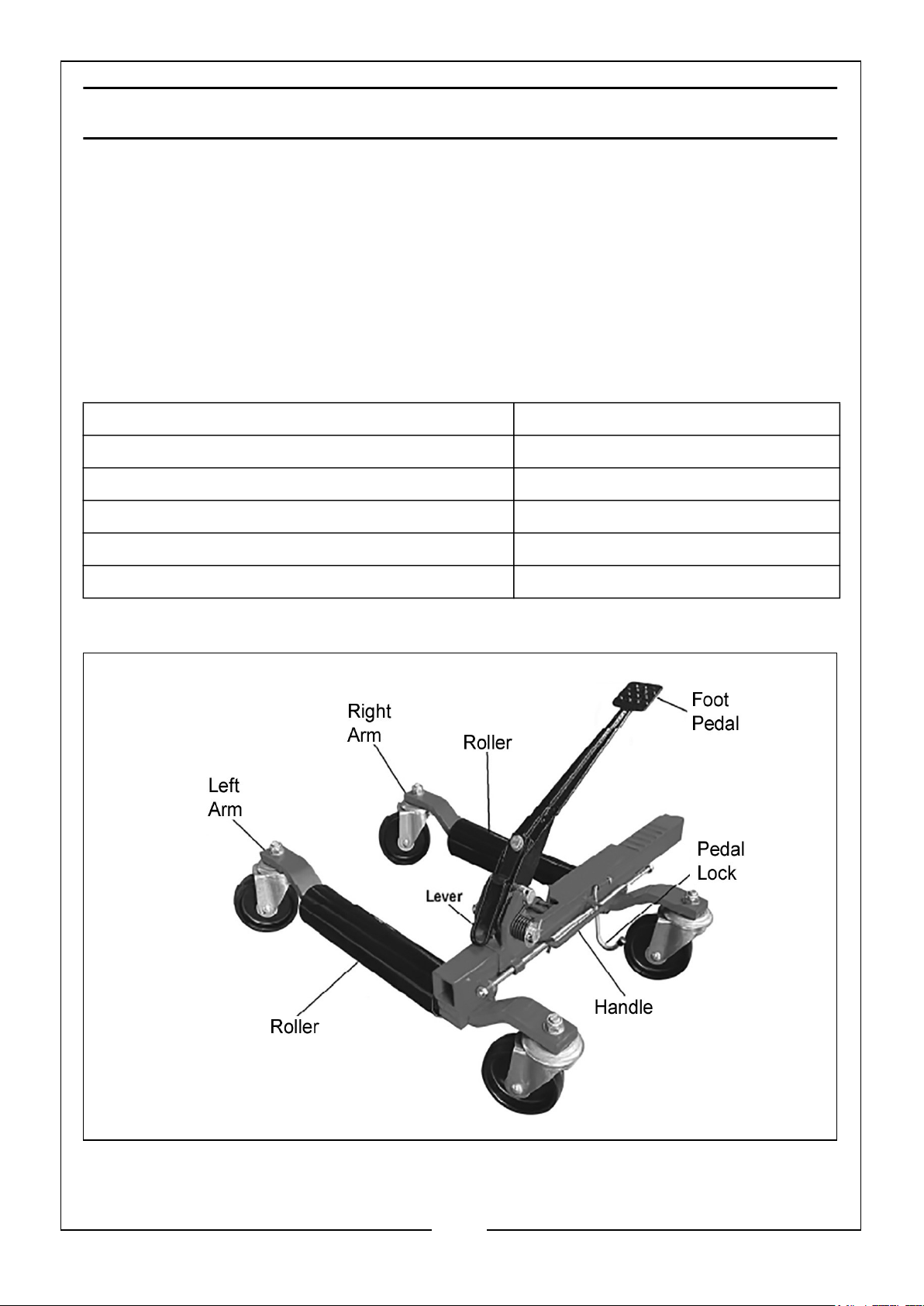
OVERVIEW
2
Parts & Service: 020 8988 7400 / E-mail: [email protected] or [email protected]
Page 3

SAFETY PRECAUTIONS
GENERAL
1. ALWAYS read and ensure you fully understand the following precautions and the
hazards associated with this product. DO NOT allow anyone who has not read
these instructions to use this jack.
2. Only use this jack for its intended purpose.
3. NEVER carry out any modifications to this product. If experiencing difficulty of
any kind consult your local dealer.
4. ALWAYS use appropriate safety equipment such as protective footwear when
using this jack.
WORK AREA
1. DO NOT use the jack on inclined surfaces. It must only be used on level ground.
The jack may move away as soon as it lifts the tyre from the ground surface.
2. DO NOT overload the jack beyond the load rating (680 kg per jack).
3. DO NOT start the vehicle engine with the jack in use. The jacks are only designed
for hand manoeuvering vehicles.
4. DO NOT use the jack to lift tyres wider than 300mm (12 inches).
5. DO NOT attempt to push the jack over obstacles when supporting a vehicle. It is
only designed to be used on level and reasonably smooth surfaces.
6. Only use the jack on level and solid ground, preferably concrete. Never use it on
soft/unmade ground as the jack may sink in.
7. Make sure that non-essential persons keep a safe distance whilst the jack is in
use.
8. This product is not intended to support the vehicle permanently, only for moving.
9. NEVER work underneath a vehicle supported only by this product. If working
under a vehicle, always use stands designed for the purpose.
10. ALWAYS the jack in a well lit work area.
11. Keep the work area clean and tidy and free from unrelated items.
REPAIRS
1. Check the jack for damage before use and DO NOT use if damaged. Any damage
should be properly repaired or the defective part replaced. If in doubt, DO NOT
use. Consult your local dealer.
3
Parts & Service: 020 8988 7400 / E-mail: [email protected] or [email protected]
Page 4
2. ALWAYS use spare parts supplied by Clarke International. Using non-standard
parts could be extremely dangerous. When necessary, have your jack repaired by
a qualified technician. This will ensure that the safety of the jack is maintained.
3. Ensure that the jack is properly maintained at all times and that no corrosion or
other damage is allowed to weaken any part of it.
4. NEVER use the jack if it has been subjected to excess load (over 680 kg) or
shock. The jack should be removed from service immediately and fully inspected
by qualified personnel and passed as serviceable before being used again.
5. Store in a dry place. In the event of damage or broken components, replacements
are available from Clarke Parts & Service.
Please keep these instructions in a safe place for future reference.
ENVIRONMENTAL PROTECTION
If disposing of this product or any damaged components, do not dispose of with
general waste. This product contains valuable raw materials and should be taken to
your local civic amenity site for recycling of metal products.
ASSEMBLY
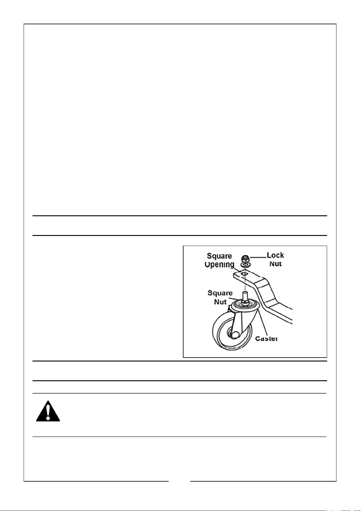
Assembly on a flat, level surface.
Attach the casters, making sure the
square nuts seat inside the square
openings.
Thread the locknuts onto the caster
bolts, securing tightly.
A key should be supplied for tightening
the nuts.
OPERATION
WARNING: MAKE SURE THAT THE SAFETY PRECAUTIONS ARE
STRICTLY FOLLOWED. NO RESPONSIBILITY CAN BE ACCEPTED FOR
INCORRECT USE OF THE JACK
Before use, visually inspect the jack for distortion of parts, cracked welds, damaged
castors, oil leaks, or any other sign of damage. Should any of these be apparent, have
the jack inspected and repaired by a qualified technician before putting back into use
4
Parts & Service: 020 8988 7400 / E-mail: [email protected] or [email protected]
Page 5
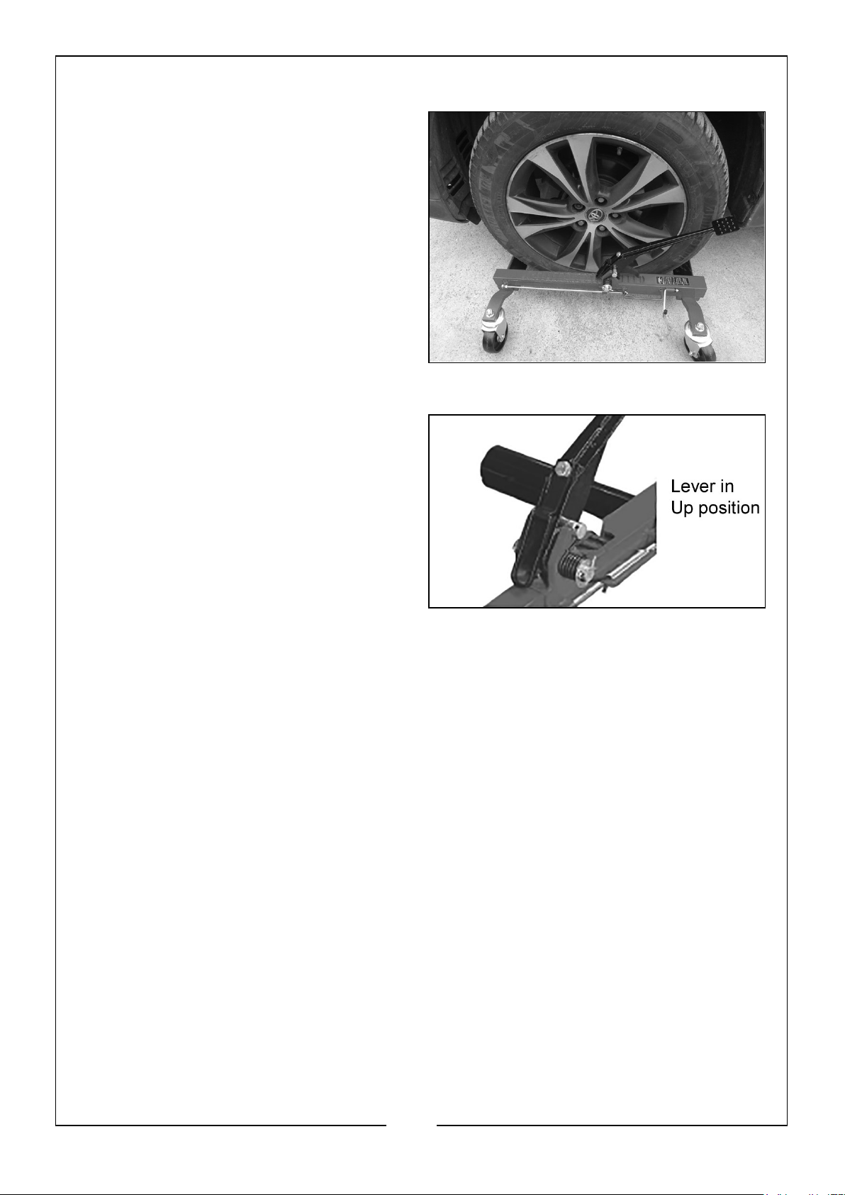
1. Release the foot pedal by depressing it and disengaging the Pedal Lock.
2. With the lever in the down position,
roll the dolly in front of the tyre,
spreading the arms apart, then push
the dolly forward so that the rollers
are on either side of tyre.
3. Ensure the jack is parallel to the sidewall of the tyre. Leave clearance
between the tyre wall and the jack
frame.
4. Move the lever to the UP position,
then pump the foot pedal until the
tyre is just lifted off the ground.
5. Always use the brakes on each of the
front swivelling castors to prevent the
vehicle moving unintentionally once
supported clear of the ground.
6. Repeat the process with the other
tyres and jacks (if purchased). Use
two jacks to move the front or back
of the vehicle. Use four jacks for
complete mobility.
7. To move the front or back of the car you will require two jacks. To position the
whole car and move it around you will require four jacks.
WARNING! Be ready for any movement the vehicle may make when the
other tyre(s) come off the ground.
8. Ensure that you have sufficient assistance and manpower to safely guide and
control the vehicle.
Repeat “Lifting the Tyre” for the other tyre(s). Use only in pairs.
WARNING! Stay clear of any sloping areas or entry ramps, however shallow
they may appear. Sufficient space should be allowed between the side of
the vehicle and an adjacent wall for the vehicle to be withdrawn from its
location in a sideways manner.
LOWERING THE TYRE
1. Move the lever to the DOWN position, then depress and release the foot pedal.
2. The beams of the jack should move apart under the weight of the vehicle and the
jack may be removed when the rollers are no longer bearing any weight.
3. Once tyre is on the ground, spread the arms and remove the dolly. Push the arms
together, then depress the foot pedal all the way and secure with the pedal lock.
5
Parts & Service: 020 8988 7400 / E-mail: [email protected] or [email protected]
Page 6
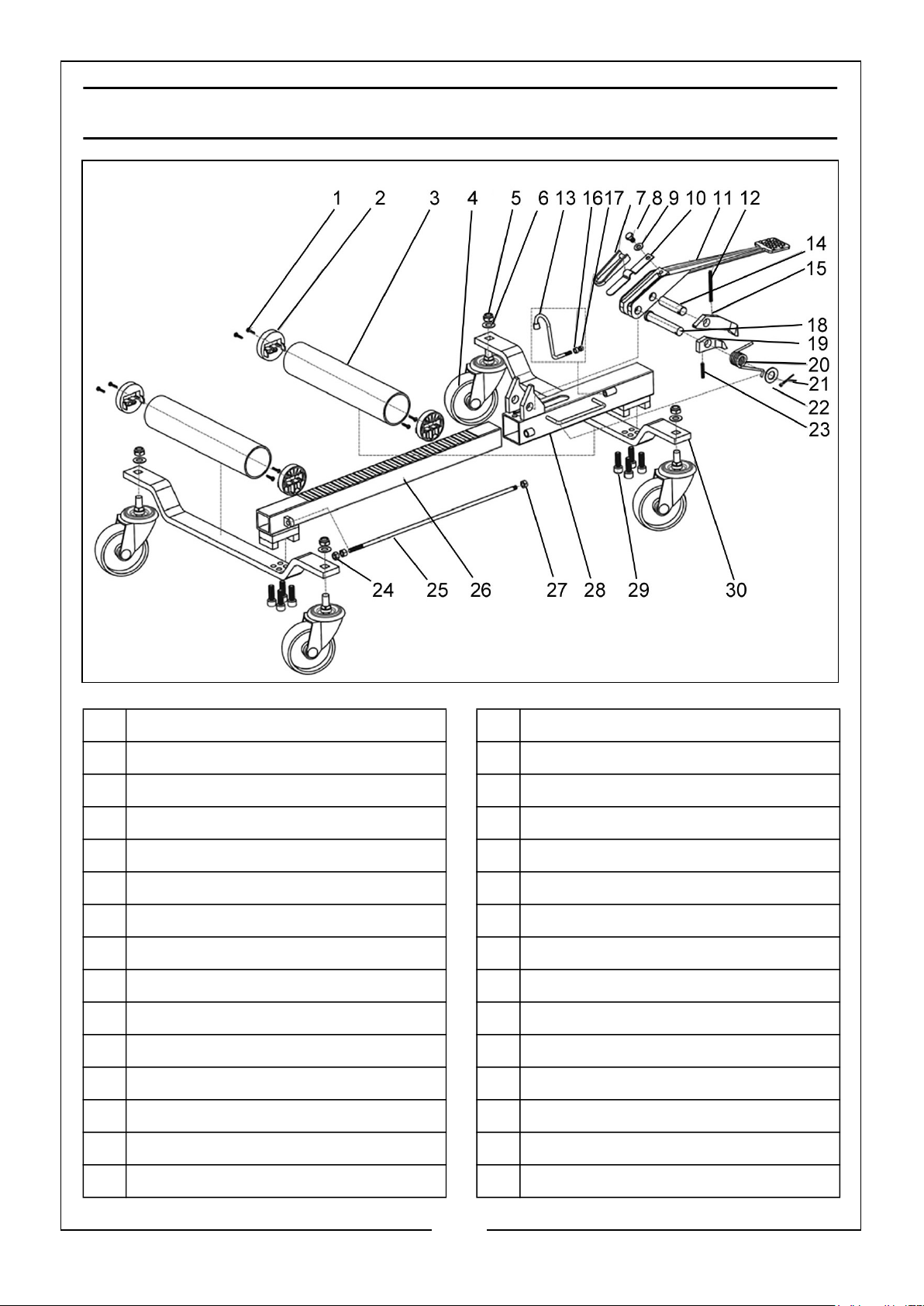
COMPONENT PARTS
1 Bearing locking screw 16 Rectangular sealing ring
2 Roller bearing 17 Nut
3 Roller 18 Roll pin
4 4” swivel caster 19 Small pawl
5 Lock nut M12 20 Torsion spring
6 Washer 21 Washer
7 Wrench 22 Circlip
8 Screw 23 Spring
9 Washer 24 Nut for rod
10 Spring plate 25 Rod
11 Foot pedal 26 Inner body & axle assembly
12 Spring 27 Lock nut M8
13 Hook 28 Outer body & axle assembly
14 Roll pin 29 Hex socket head cap screw M10
15 Large pawl 30 Flat iron
6
Parts & Service: 020 8988 7400 / E-mail: [email protected] or [email protected]
Page 7
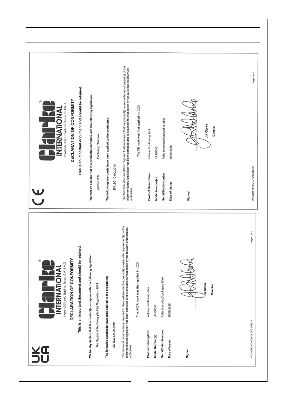
DECLARATIONS OF CONFORMITY
7
Parts & Service: 020 8988 7400 / E-mail: [email protected] or [email protected]
Page 8
 Loading...