

Page 1
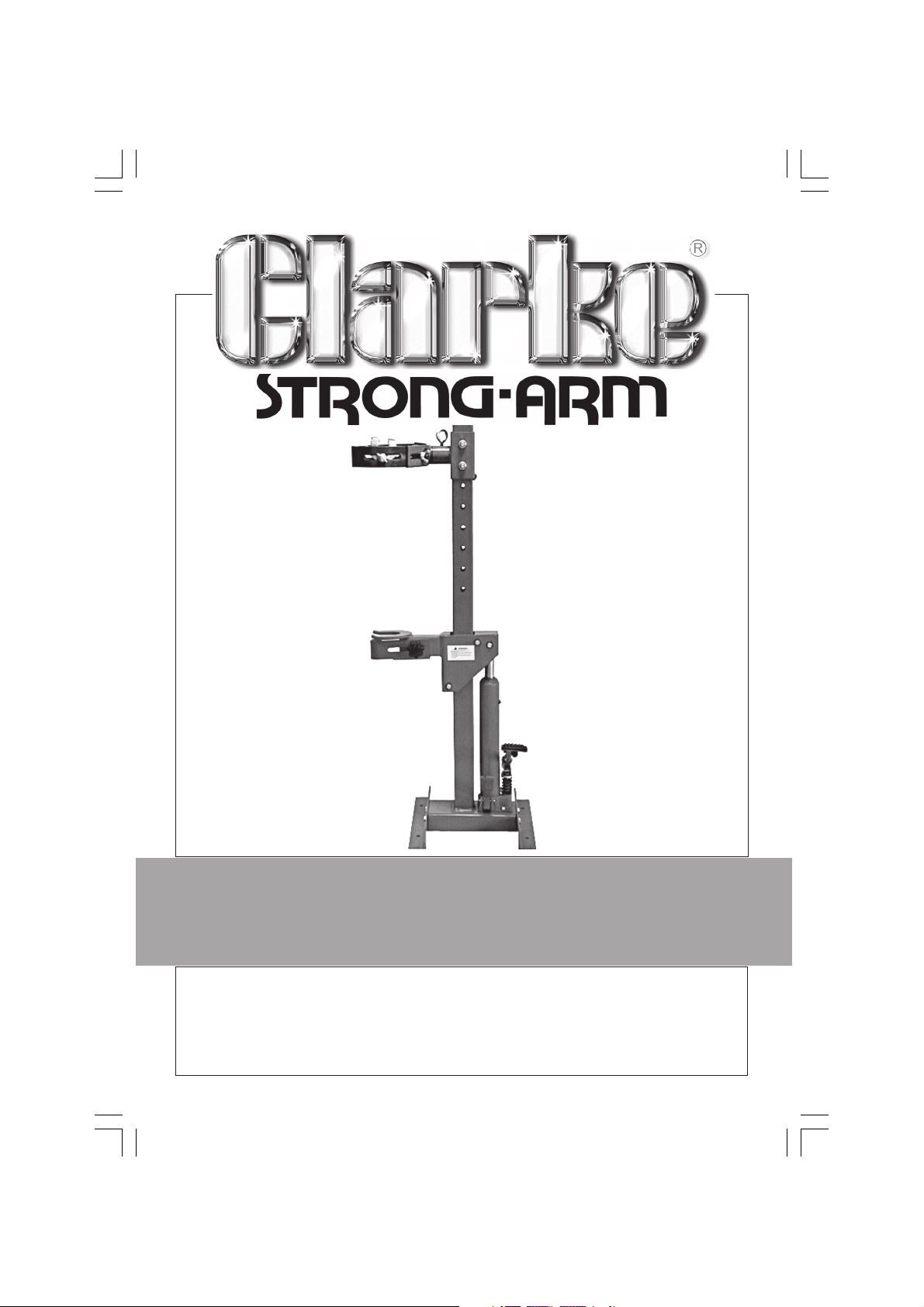
STRUT SPRING COMPRESSOR
STRUT SPRING COMPRESSOR
MODEL No: SSC1000
Part No: 7630066
USER INSTRUCTIONS
0310
Page 2

SPECIFICATIONS
Spring Rating Max. ............................. 1000 kg
Spring Length ..................................... 102 - 254 mm /4 in-10 in
Maximum Spring Diameter ............ 350 mm
Ram Stroke ......................................... 340 mm
Dimensions ......................................... 553 x 495 x 1185 mm
Weight ................................................ 31.5 kg
International, Hemnall Street, Epping, Essex CM16 4LG
2
Page 3
Thank you for purchasing this CLARKE Coil Spring Compressor, designed for used
by qualified tradesmen ONLY.
Please read this instruction leaflet thoroughly before use to ensure it is used correctly
and that all safety precautions are observed.
GUARANTEE
This CLARKE product is guaranteed against faulty manufacture for a period
of 12 months from the date of purchase. Please keep your receipt as
proof of purchase. This guarantee is invalid if the product is found to have
been abused or tampered with in any way, or not used for the purpose
for which it was intended.
Faulty goods should be returned to their place of purchase, no product
can be returned to us without prior permission.
This guarantee does not effect your statutory rights.
SAFETY PRECAUTIONS
• The Coil Spring Compressor should be securely fixed to the workshop floor,
using proper foundation bolts - NOT supplied.
• ONLY qualified mechanics/technicians should use this equipment.
• ALWAYS inspect before use. DO NOT use if components are damaged in any
way, or if the hydraulic ram is leaking.
• ALWAYS keep hands clear of moving parts.
• ALWAYS wear safety goggles, manufactured to the latest European safety
standards. Everyday glasses do not have impact resistant lenses, they are NOT
safety glasses.
• ALWAYS keep work area clean. Cluttered areas and benches invite accidents.
•
ALWAYS ensure that adequate lighting is available. A minimum intensity of 300 lux
should be provided. Ensure the lighting is placed so you will not be working in your
own shadow.
• ALWAYS concentrate on the job at hand, no matter how trivial it may seem. Be
aware that accidents are caused by carelessness due to familiarity.
• DO NOT use if under the influence of alcohol or drugs.
• DO NOT make any modifications to this equipment.
• Should repairs be necessary, ensure they are carried out by a qualified
technician, and that all parts are those supplied by CLARKE International. A
failure to observe these precautions will invalidate the guarantee.
3
Page 4
ASSEMBLY
Unpack the carton and lay out the components.
Should any damage be apparent, please contact your
Clarke dealer immediately.
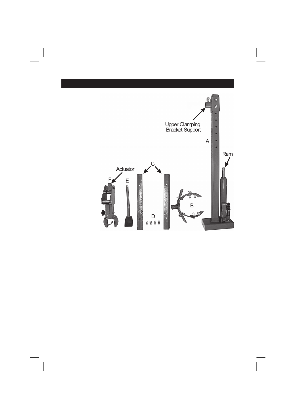
The carton comprises the following items:
A Main Column
B Upper Clamping Bracket complete
C 2 x Feet
D 4 x Nuts, Bolts and washers.
E Foot Pedal
F Lower Support Bracket
1. Bolt on the two feet using the four nuts, bolts and washers provided.
2. Raise the column on to its feet, then remove the two bolts securing the Upper
Clamping Bracket Support, and pull it off the column.
3. Lower the Lower Support Bracket (F) on the column so that the Actuator makes
contact with the Ram.
Ensure the Hex. socket head grub screw in the Actuator is screwed out sufficient
for the actuator to bottom out on the ram, then tighten the grub screw.
4. Replace the Upper Clamping Bracket Support and tighten the nuts (see Method
of Operation).
5. Insert the pedal into the receptacle on the Hydraulic Ram and secure with the
bolt provided.
6. Unscrew the ring bolt in the Upper Clamping Bracket Support and insert the
Upper Clamping Bracket. Screw in the ring bolt to secure the Clamping Bracket.
We Strongly recommend that the assembly is bolted to the workshop floor for
maximum stability. This should be done using proper foundation bolts.
Your Coil Spring Compressor is now ready for use.
4
Page 5
METHOD OF USE
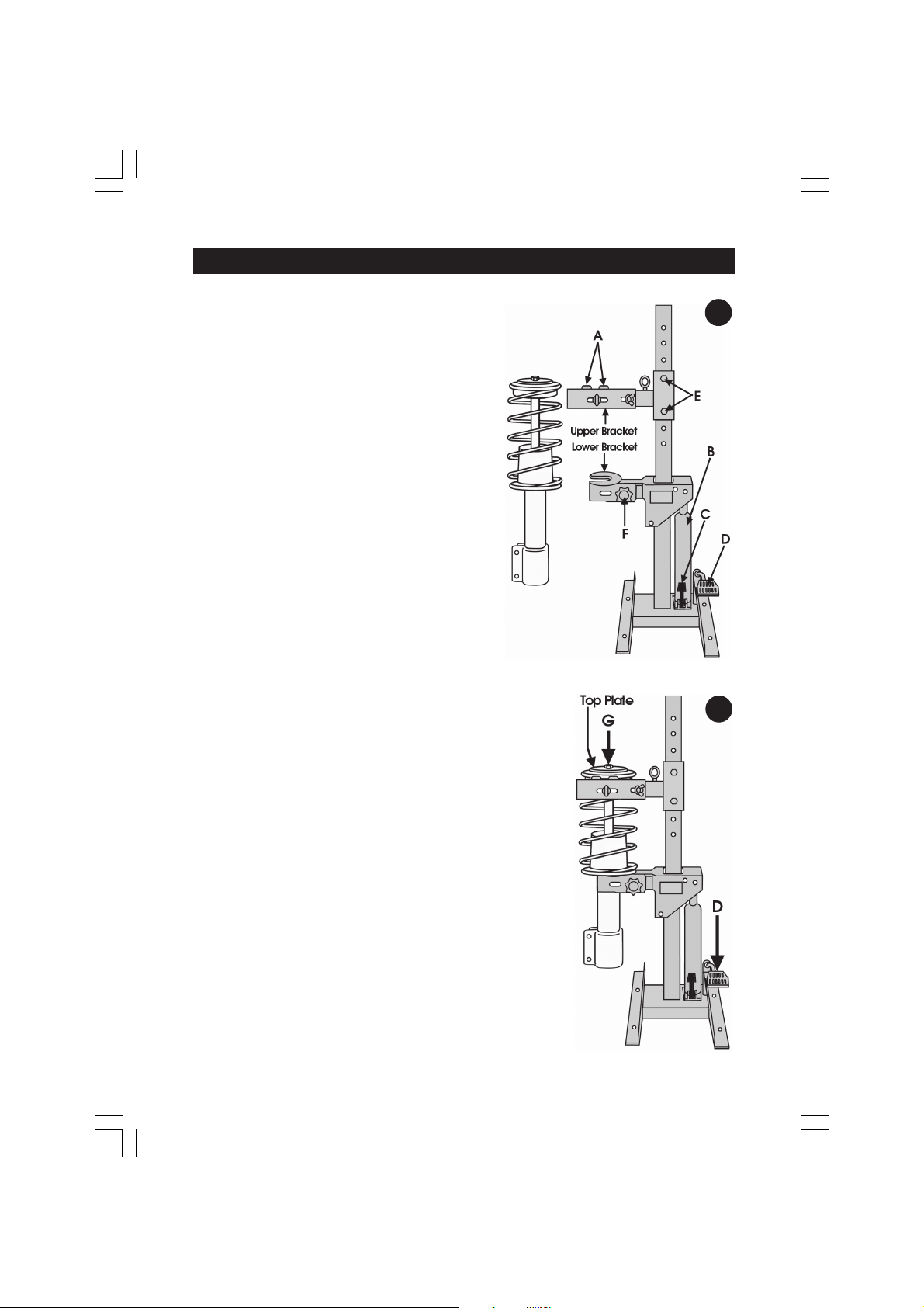
1. Lower the ram to its lowest position by
pressing and holding down pedal ‘C’.
Hinge the upper brackets back,
2. Slide the strut of the spring assembly into
the lower bracket and clamp using
the facility provided and knob ‘F’. Do not
overtighten - it should be firm only.
3. Position the Upper Bracket so that the
two clamps ‘A’ fit snugly and squarely
around the spring coils, as near to the top
of the assembly as possible.
It may be necessary to remove the two bolts
securing the upper bracket assembly ‘E’, and
slide the bracket up or down by the
appropriate amount in order to locate the
clamps ‘A’ correctly. Ensure the bolts ‘E’ are
tightened before proceeding.
Sufficient adjustment to the upper bracket
components is provided, in all directions, in order
to ensure the clamps sit squarely and snugly on the
spring coils. Ensure all wing nuts and adjusters are
finger tight only...DO NOT fully tighten.
4. Once secured, pump the lever ‘D’, until pressure
on the shock absorber securing nut ‘G’ is
completely relieved, detected when the nut turns
easily. WARNING! DO NOT undo the nut until this
condition exists.
1
2
5. With the nut removed, pull off the top plate.
6. With the top plate removed, carefully and gently
press lever ‘C’ to allow the spring to fully reassert.
When all pressure on the spring is relieved, undo all
upper bracket constraints and remove the spring.
7. Support the shock absorber whilst undoing the lower
bracket constraint using knob F. The shock absorber
may then be withdrawn.
8. Reassembly is in reverse order
5
Page 6
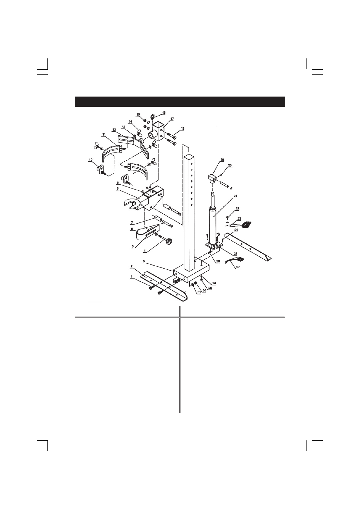
COMPONENTS
No. Description Qty Part No.
1 Bolt 4 JHCHT45401
2 Bracket 2 JHCHT45402
3 Upright 1 JHCHT45403
4 Screw Rod 1 JHCHT45404
5 Adj. Strut Shaft Clasp 1 JHCHT45405
B Handle Sleeve 3 JHCHT45406
7 Bushing 2 JHCHT45407
8 Lower Strut 1 JHCHT45408
9 Retaining Ring 6 JHCHT45409
10 Spring Clasp 2 JHCHT45410
11 Spring Clasp Holder 2 JHCHT45411
12 Spring Clasp Bracket 1 JHCHT45412
13 Washer 7 JHCHT45413
14 Fly Nut 4 JHCHT45414
15 Nut 2 JHCHT45415
16 Screw Ring 1 JHCHT45416
No. Description Qty Part No.
17 Upper Strut Support 1 JHCHT45417
16 Bolt 2 JHCHT45418
19 Saddle 1 JHCHT45419
20 Screw 11 JHCHT45420
21 Bottle Jack 1 JHCHT45421
22 Bolt 1 JHCHT45422
23 Lift Foot Pedal 1 JHCHT45423
24 Bolt 2 JHCHT45424
25 R-pin 1 JHCHT45425
26 Pin 1 JHCHT45426
27 Release Foot Pedal 1 JHCHT45427
28 Washer 3 JHCHT45428
29 Nut 2 JHCHT45429
30 Nut 4 JHCHT45430
31 Washer 4 JHCHT45431
6
Page 7

MAINTENANCE
Maintenance is limited to inspecting before each use to ensure all parts are secure
and completely undamaged.
Maintain the unit in a clean condition at all times and ensure there is no distortion
of components.
Inspect the ram to ensure there is no leakage. Should any be apparent, remove
the unit from service and have the ram repaired by Clarke International or a
reputable qualified service agent.
NOTE: A very slight seepage is acceptable. At Monthly intervals, remove the Oil
Level Plug in the ram cylinder and check to ensure the oil level is correct. If
necessary, top up using CLARKE hydraulic oil so that oil is level with the hole.
When not in use, the unit must be stored (if necessary) in a cool dry environment,
with the ram in the fully retracted position.
A light lubrication of the column will assist in providing smooth operation when
raising, lowering the ram.
7
Page 8
 Loading...