

Page 1
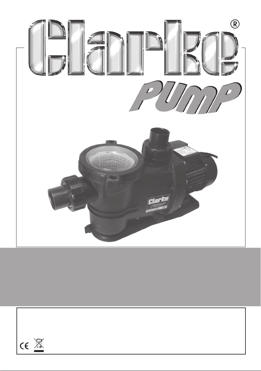
SWIMMING POOL PUMPS
Models SPP07, SPP10 & SPP15
Part Nos: 7175025, 7175030 & 7175035
OPERATING & MAINTENANCE
INSTRUCTIONS
GC0514
Page 2

INTRODUCTION
Thank you for purchasing this CLARKE swimming pool pump.
Before attempting to operate the pump, it is essential that you read this
manual thoroughly and carefully follow all instructions given. In doing so you
will ensure the safety of yourself and that of others around you, and you can
also look forward to the pump giving you long and satisfactory service.
DESCRIPTION
This self-priming, centrifugal swimming pool pump is designed for the filtration
of small to medium size swimming pools and for pumping clean water only.
Operating with contaminated or salt water should be avoided.
When used with permanently installed pools, the pump should be fixed in a
horizontal position and the use of a non-return valve will facilitate immediate
priming. The pump inlet is higher than the impeller inlet so that it can start
operating when only the pump body is filled with water.
Upon receipt, any damage or deficiency should be reported to your CLARKE
dealer immediately.
CONTENTS
1 x Swimming Pool Pump (c/w integral Pre-filter Basket)
2 x Inlet /Outlet Connectors
2 x Inlet /Outlet Connector Fixing Nuts
2 x Inlet /Outlet Connector O-Ring Seals
1 x Non-return Valve
1 x Filter Cover Removal Wrench
GUARANTEE
This CLARKE product is guaranteed against faulty manufacture for a period of
12 months from the date of purchase. Please keep your receipt as proof of
purchase.
This guarantee is invalid if the product is found to have been abused or
tampered with in any way, or not used for its intended purpose.
Faulty goods should be returned to their place of purchase, no product can
be returned to us without prior permission.
This guarantee does not effect your statutory rights.
2
Parts & Service: 020 8988 7400/E-mail:[email protected] or [email protected]
Page 3

GENERAL SAFETY PRECAUTIONS
WARNING: This swimming pool pump is not a submersible pump. On
no account should it ever be immersed in water.
Always connect the pump to an earthed power supply via a RCD.
1. ALWAYS keep the pump room clean and well lit. Floors should always be
kept clear. Cluttered or dark areas invite accidents.
2. NEVER over-reach. Keep your proper footing and balance at all times
when installing or maintaining the pump.
3. NEVER direct any water discharge towards electrical wiring or equipment.
4. ALWAYS thoroughly familiarise yourself with this pump & its operation, and
follow all instructions in this manual. Never allow persons unfamiliar with
these instructions to operate the pump.
5. ALWAYS ensure that the pump is properly installed to prevent it from
moving during operation, and that the immediate area surrounding the
pump is kept clear.
6. ALWAYS maintain the pump with care and keep it clean for best / safest
performance.
7. NEVER use this product if any part is damaged. Have it inspected and
repaired by your local Clarke dealer. Always turn the pump off before
carrying out any maintenance.
8. NEVER modify this pump in any way. Use it ONLY for the purpose for which
it is designed.
9. NEVER use for pumping flammable liquids or corrosive chemicals. This
pump is designed to pump clean water only.
10. NEVER switch the pump ON when the pool is in use. ALWAYS disconnect
the pump from the electrical supply when the pool is in use.
11. This pump must be connected to an earthed power supply via a RCD.
12. ALWAYS have the pump serviced by your local CLARKE dealer, using only
identical replacement parts. This will ensure the safety of the pump is
maintained. The use of non standard parts could be hazardous.
Your CLARKE water pump has been designed to give long and trouble free
service. If, however, having followed the instructions in this booklet carefully,
you encounter problems, take the unit to your local CLARKE dealer.
Please keep these instructions in a safe place for future reference.
3
Parts & Service: 020 8988 7400/E-mail:[email protected] or [email protected]
Page 4
ELECTRICAL CONNECTIONS
WARNING! Read these electrical safety instructions thoroughly
before connecting the product to the mains supply.
Before switching the product on, make sure that the voltage of your
electricity supply is the same as that indicated on the rating plate. This
product is designed to operate on 230VAC 50Hz. Connecting it to any other
power source may cause damage.
This product may be fitted with a non-rewireable plug. If it is necessary to
change the fuse in the plug, the fuse cover must be refitted. If the fuse cover
becomes lost or damaged, the plug must not be used until a suitable
replacement is obtained.
If the plug has to be changed because it is not suitable for your socket, or
due to damage, it should be cut off and a replacement fitted, following the
wiring instructions shown below. The old plug must be disposed of safely, as
insertion into a mains socket could cause an electrical hazard.
WARNING! The wires in the power cable of this product are
coloured in accordance with the following code:
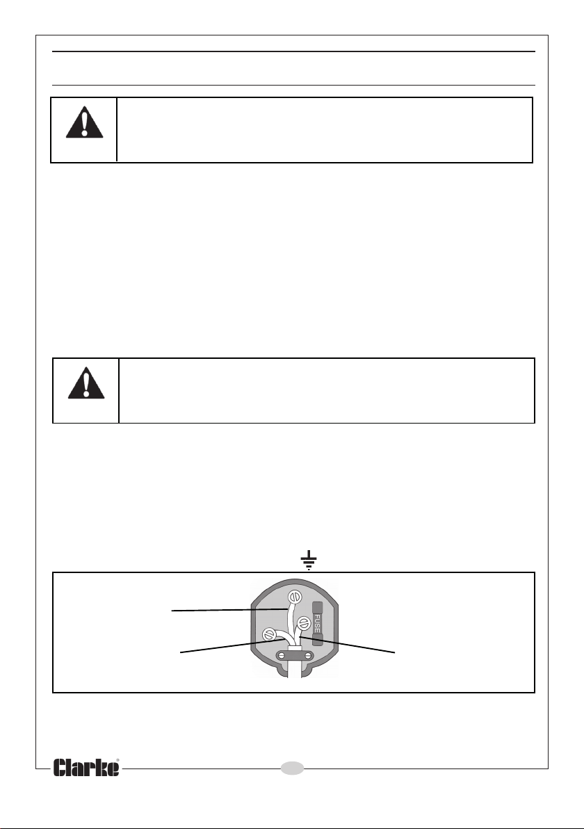
Blue = Neutral Brown = Live Yellow & Green = Earth
If the colours of the wires in the power cable of this product do not
correspond with the terminal markings of your plug, proceed as follows:
• The wire which is coloured Blue must be connected to the terminal
which is marked N or coloured Black.
• The wire which is coloured Brown must be connected to the
terminal which is marked L or coloured Red.
• The wire which is coloured Yellow & Green must be connected to
the terminal which is marked E or or coloured Green.
Plug must be BS1363/A approved
Earth Always fit a 13 Amp fuse.
(Green and Yellow)
Neutral Live
(Blue) (Brown)
Ensure that the outer sheath of the cable is firmly held by the clamp
Always connect this product to the mains supply via a Residual Current
Device (RCD)
If in any doubt, consult a qualified electrician. DO NOT attempt any repairs
yourself.
4
Parts & Service: 020 8988 7400/E-mail:[email protected] or [email protected]
Page 5
INSTALLATION
Because of the variety of possible installations, no plumbing accessories are
supplied with your pump, however accessories are available from your
nearest CLARKE dealer. Contact your CLARKE dealer for further information,
or CLARKE International Sales Department on 01992 565333.
Note: It is recommended that the end user should consult a qualified installer
if there are any doubts as to the suitability of this product for a particular
installation.
IMPORTANT: The pump MUST NOT be connected to the mains power supply
until all hose/pipe installation is completed.
INSTALLATION OF THE PUMP
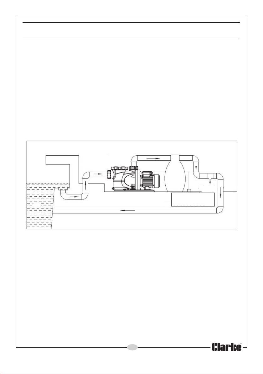
Pool Side
Skimmer
outlet
Pool
A typical installation of the pump is shown in Fig 1. The pump must always be
installed and operated in a horizontal position i.e. with the outlet port facing
vertically upwards. The fixing holes in the base should be used to secure the
pump firmly in it’s operating position. Mount the pump on raised blocks or a
purpose built platform to protect it from flooding.
Always ensure there is adequate air circulation around the motor and that
the transparent filter cover is accessible so that the filter basket can be
removed for cleaning. The pump should be installed in a dry, well ventilated
enclosure, sheltered from rain, such as a purpose built pump room.
The pump is usually installed between the pool skimmer and the pool filter
and should be positioned as near to the pool water level as possible.
Pool Filter
Remote Power
Connection
Fig 1
5
Parts & Service: 020 8988 7400/E-mail:[email protected] or [email protected]
Page 6

ELECTRICAL CONNECTION
The pump should be located at a safe distance, (usually 2 metres), away
from the pool, and the power supply should be at least 3.5 metres from the
pool. If in doubt, please contact your electrical specialist and refer to the
International Electrical Commission (IEC) standard, (Electrical Installations for
Buildings-part 7), referring to ‘swimming pools and other basins’.
Avoid situations where the pump could become drenched with water as
neither the motor or terminal box are designed to be waterproof. Ensure the
pump & its cable do not create a safety hazard for people walking past it.
PIPE/HOSE CONNECTIONS
The pump inlet will be connected to the pool skimmer and/or pool drain
connection, depending upon the installation layout, and the discharge
outlet should be connected to your water filter.
The inlet and outlet adaptors supplied with the pump are designed to fit to
rigid pipe-work. The inner bore diameter of the adaptors is 50 mm. Therefore
pipes with the same nominal diameter should be used. These should be fixed
in place using a proprietary adhesive/sealant suitable for pressurised pipework applications.
These can be extended with the use of suitable 50 mm I/D hose secured with
a worm drive clip. Ensure all connections are air tight. Tighten them enough
to secure the hose during pressurised operation, but not so tight as to crack
the plastic inlet/outlet connectors.
Where the pump is to be a permanent fixture, vibration and strain on
adjacent parts can be reduced by the insertion of a short flexible section of
hose between any rigid pipework and the immediate area of the pump.
Any air leaks in the suction line will inhibit priming and reduce the capacity of
the pump. Ensure there are no kinks in any flexible hose used.
The performance of your pump will be affected by the diameter of the inlet
pipe - any restriction will greatly reduce the flow. We recommend that you
always use a pipe diameter at least equal to, or greater than the diameter of
the pump connections i.e. 50 mm diameter.
To prevent unnecessary strain or possible distortion to the pump, ensure that
adequate support is provided to the hoses and or pipes. They will be
considerably heavier when filled with water.
It is suggested that suction and delivery isolation valves are fitted in order to
isolate the pump. A gate valve may be installed in-line on the delivery side
(outlet port) of the pump which can be adjusted as required to regulate the
flow of water and can assist in priming the pump.
Protect the pump and pipework from freezing with the addition of suitable
lagging. The formation of ice may cause serious damage.
6
Parts & Service: 020 8988 7400/E-mail:[email protected] or [email protected]
Page 7
OPERATION
1. Open any valves in the pipeline.
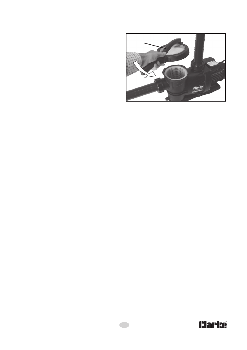
2. If operating the pump for the first
Wrench
time, unscrew the filter cover on
top of the pump using the wrench
supplied and prime the pump by
filling completely with water.
Note: The pump is only self- priming
when filled with water. Refilling is
only necessary if the pump has
been drained, or if all the water
has been lost.
3. Connect to the power supply and switch on. Water should start to flow
through the system. Check for any leaks and repair as necessary.
4. If the motor fails to start, or the pump does not deliver water, refer to
TROUBLESHOOTING on page 9. Never operate the pump when not filled
with water or if the inlet is blocked.
• The level of water in the pump can be seen through the transparent
filter cover.
Note: Filling the suction pipe with water will speed up the priming process,
and it is suggested that a non-return valve be fitted to the end of the
suction pipe.
5. Stop the pump by switching off the power supply.
CARE DURING USE
Fig 3
1. Do not allow the pump to run dry, otherwise the seal between the pump
and motor may be damaged. If a leak is noticed at this point, it may
indicate that the seal is worn and therefore in need of replacement.
Contact your CLARKE dealer, or the Clarke International Service
Department for advice.
2. In the event of a blockage, where debris has entered the suction
chamber, the sieve and chamber can be cleaned out as described
under MAINTENANCE.
3. Should contaminants come into contact with the pump, flush through with
cold water as soon as possible to prevent damage to the pump. DO NOT
USE for pumping chemicals or other corrosive liquids (other than pool
purification chemicals in their correct mix ratio).
4. If the pump is being used to drain the pool, ensure there is adequate
drainage and there is no risk of damage to property as a result of water
being discharged. If a flexible hose must be laid across a roadway,
protect it with wooden planking.
7
Parts & Service: 020 8988 7400/E-mail:[email protected] or [email protected]
Page 8
MAINTENANCE
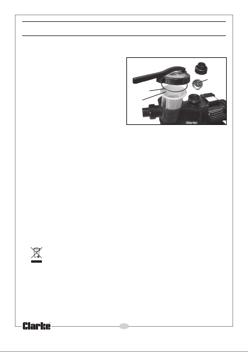
The only maintenance required is a regular inspection to ensure that debris is
not blocking the passage of water through the pump.
Clean the filter basket periodically
after closing any inlet and delivery
valves and removing the filter cover,
using the wrench provided. Lift out
the filter basket and clean it in water,
check the cover O-ring is in good
condition before reassembly.
If you suspect the pump is blocked
by silt, leaf debris etc, disconnect it
from the mains supply and backflush
to clear any blockage though the
drain plug. You will need to disconnect the outlet hose and lift out the nonreturn valve to do this.
Always keep the pump in a clean condition, checking regularly for loose
bolts or a damaged power cable etc.
O-ring
Filter
Basket
AFTER USE
After use, and if the pump will not be used over the winter period, or
whenever there is danger of freezing, always drain the pump body. If the
pump has been used with contaminated or salty water, it should be
thoroughly flushed with clean water following use, both inside and out. It
should then be drained before replacing the drain plug, and covered over, if
not already installed in a clean, dry environment sheltered from the weather.
Remember to re-prime the pump when returning to service.
In the event that dismantling and overhaul of the pump is necessary,
contact your CLARKE International Service Department on 020-8988-7400.
Fig 4
Nonreturn
valve
ENVIRONMENTAL RECYCLING POLICY
Through purchase of this product, the customer is taking on the
obligation to deal with the WEEE in accordance with the WEEE
regulations in relation to the treatment, recycling & recovery and
environmentally sound disposal of the WEEE.
In effect, this means that this product must not be disposed of with general
household waste. It must be disposed of according to the laws governing
Waste Electrical and Electronic Equipment (WEEE) at a recognised disposal
facility.
8
Parts & Service: 020 8988 7400/E-mail:[email protected] or [email protected]
Page 9
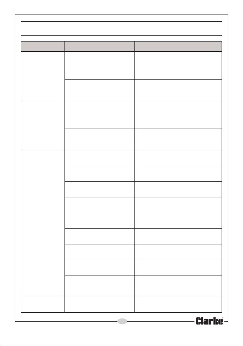
TROUBLESHOOTING
MELBORP ESUAC NOITULOS
ylppussniamoNdnaylppusrewopdesufkcehC
tonseodpmuP
.nur
fpmuP
otslia
.emirp
.dekcolb
.pmup
o
tubsnurpmuP
roopsevig
.tuptuo
fossolnedduS
.wolf
.detcurtsb
.laesdegamad
.nrowyldabsi
.enilnoitcus
oegakcolBremmiksloopdnaenilepipkcehC
noitcushguorhtskaelriA
degamad(stniojesoh
,pmalcnekorb,esoh
.esohtelnidekcolBremmiksloopdnaenilepipkcehC
enilyreviledronoitcuS
.egakaelepiptelnIrotcennocdnaepiptelnikcehC
hguorhtskaelriA
dnadegamadrellepmI
.laesroopgnikam
isessolnoitcirfhgiH
ehtn
ihoottfilnoitcusni
.hg
.epiptelnif
.dekcolb/deziesrellepmIsniammorfpmuptcennocsiD
)teksaggnittif-lli/degamad
siteksabretliftelnipmuP
edisnilairetamdetsegnoC
laeslacinahcem/rellepmI
gnitluserdetisyldabpmuP
kcehc(yrassecenfiesufecalper
uf
.rekaerb
.egakcolbraelc
.yrassecensa
f
nakcehC
.pmuphsulfkcab
.laesweneR
.riaper
.riaper
.depmup
.egakcolbrof
tiucrickcehC.)gnitares
dnaesuacetagitsevnI.ylppus
lper/snoitcennocriapeR
.nepoyllufsidettifevlav
&teksabretliftuonaelC
.sevlavrosnoitcirtser
esoheca
telniynakcehC.egakcolbro
.teksabretlifnaelcd
erusnednanoitcurtsboevomeR
.enilyrevilednisknikoneraereht
eriuqersanethgiT.skaelrof
.d
aedEKRALCruoyotnruteR
rofrel
rofrelaedEKRALCruoyotnruteR
,sevrucyrassecennudiovA
otelbissopsaesolcsapmupteS
ebotretawehtfoleveleht
9
Parts & Service: 020 8988 7400/E-mail:[email protected] or [email protected]
Page 10
TROUBLESHOOTING
MELBORP ESUAC NOITULOS
noitarbiveudnU
.esionro
ybdesuac.noitcurtsbo
.elbatsnu
.eni
lepip
.retawfowolfevissecxEyb.retawfowolfesaerceD
.metsys
epiptelniniecnatsiseR
.yrassecen
tnenopmocgnitatoresooLr
.sriaper
sipmupfonoitallatsnI
ropmupnitekcopriA
rellepmidegamaDrelaedEKRALCruoyotnruteR
.riaperrof
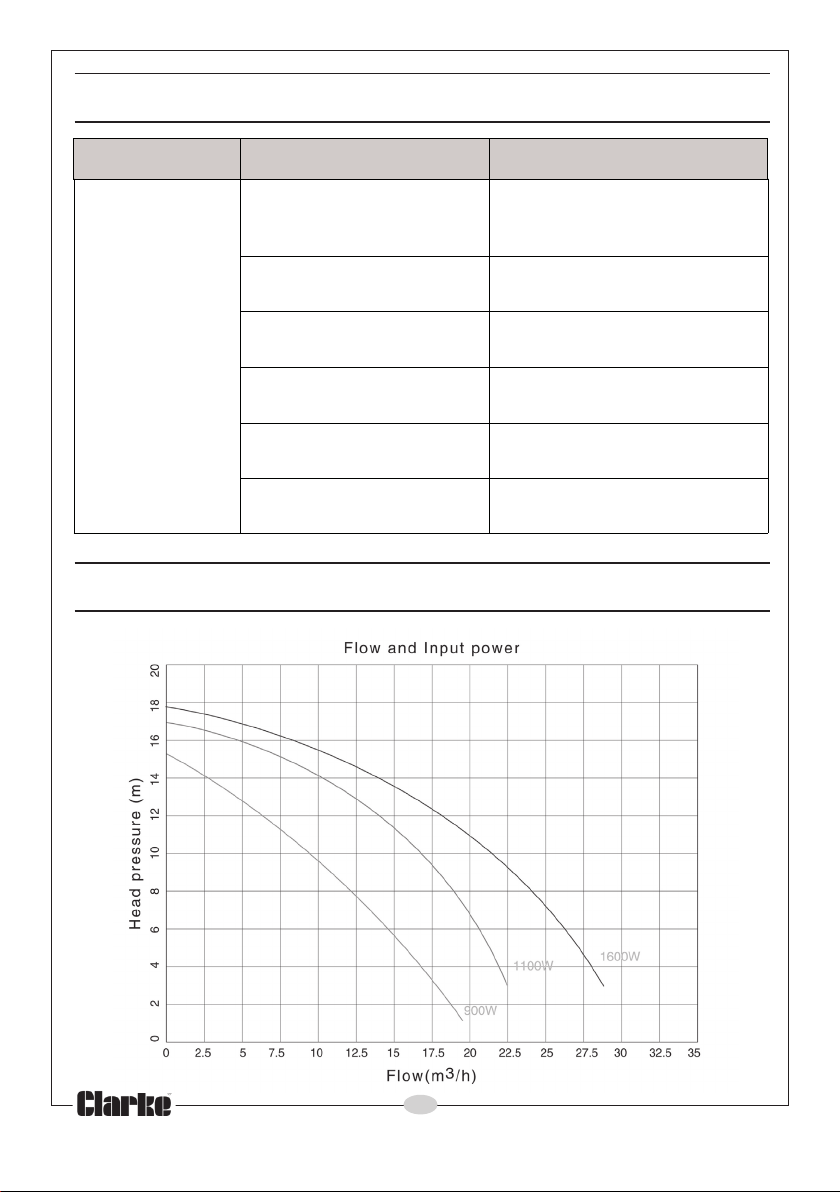
SPP07, SPP10 & SPP15 PERFORMANCE
nisevlavteltuo/telnignitsujda
satuonaelcdnaepipkcehC
ofrelaedruoyotnruteR
.noitisop-erdnapmuppotS
rellepminigulpniardesaeleR
.riaesaelerotgnisuoh
SPP15
SPP10
SPP07
10
Parts & Service: 020 8988 7400/E-mail:[email protected] or [email protected]
Page 11
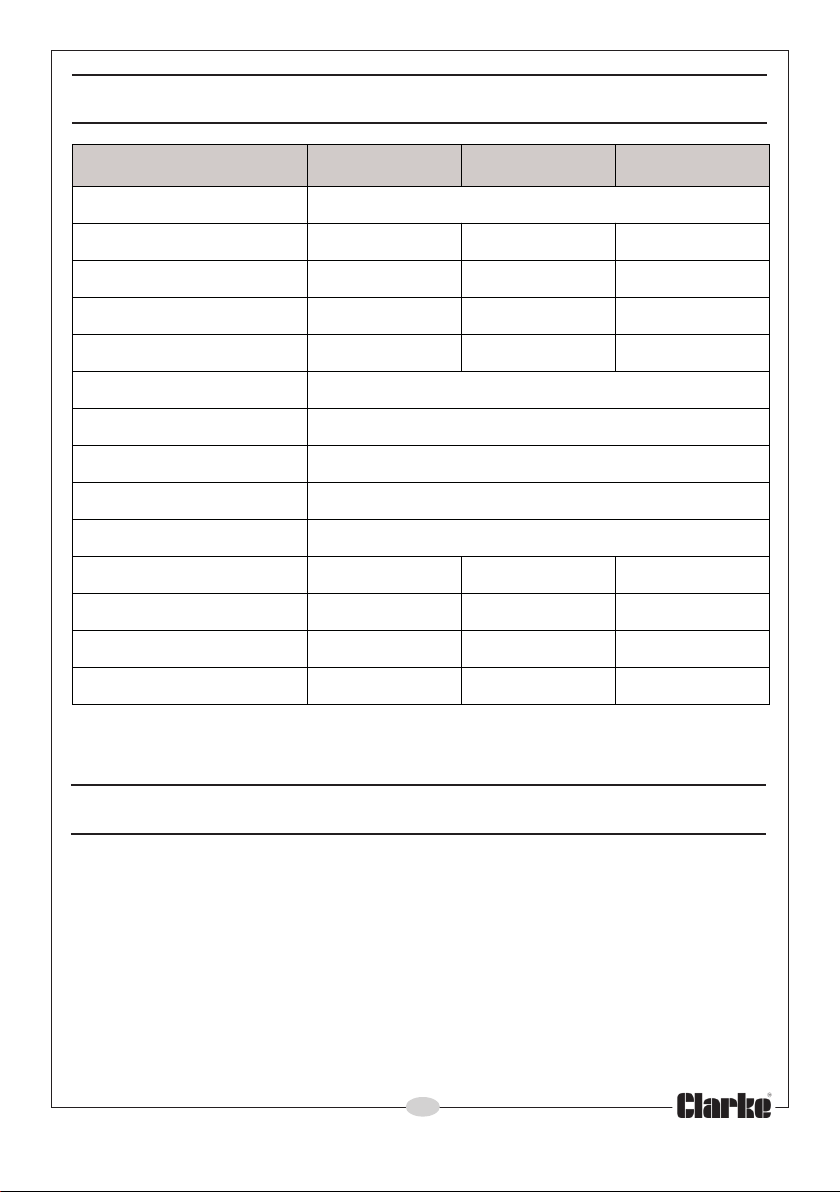
TECHNICAL SPECIFICATION
70PPS
epytpmuPlagufirtneC
thgieWgk63.01gk50.01gk39.31
)HxWxL(snoisnemiDmm572x581x555mm762x091x355mm082x091x585
olFxaMnim/L333nim/L663niM/L054
w
daeHxaMm51m51m81
erutarepmeTgnitarepOC°53
noitacifissalCretaWretaWnaelC/slooPgnim
epyTevlaVnruteRteltuotaepytpalF
eziSteltuO&telnI)mm(d/o65/d/i05
ylppuSrewoPzH05@V042-022
rewoPtuptuO)W00
leveLerusserPdnuoSApLBd1.26ApLBd8.26ApLBd2.66
leveLrewoPdnuoSAwLBd1.37AwLBd3.57Aw
rewoPdnuoSdeetnarauGAwLBd67AwLBd87AwLBd28
Please note that the details and specifications contained herein, are correct at the
time of going to print. However, CLARKE International reserve the right to change
specifications at any time without prior notice.
miwS
6(PH57.0)W057(PH1)W0511(PH5.1
01PPS
51PPS
LBd3.97
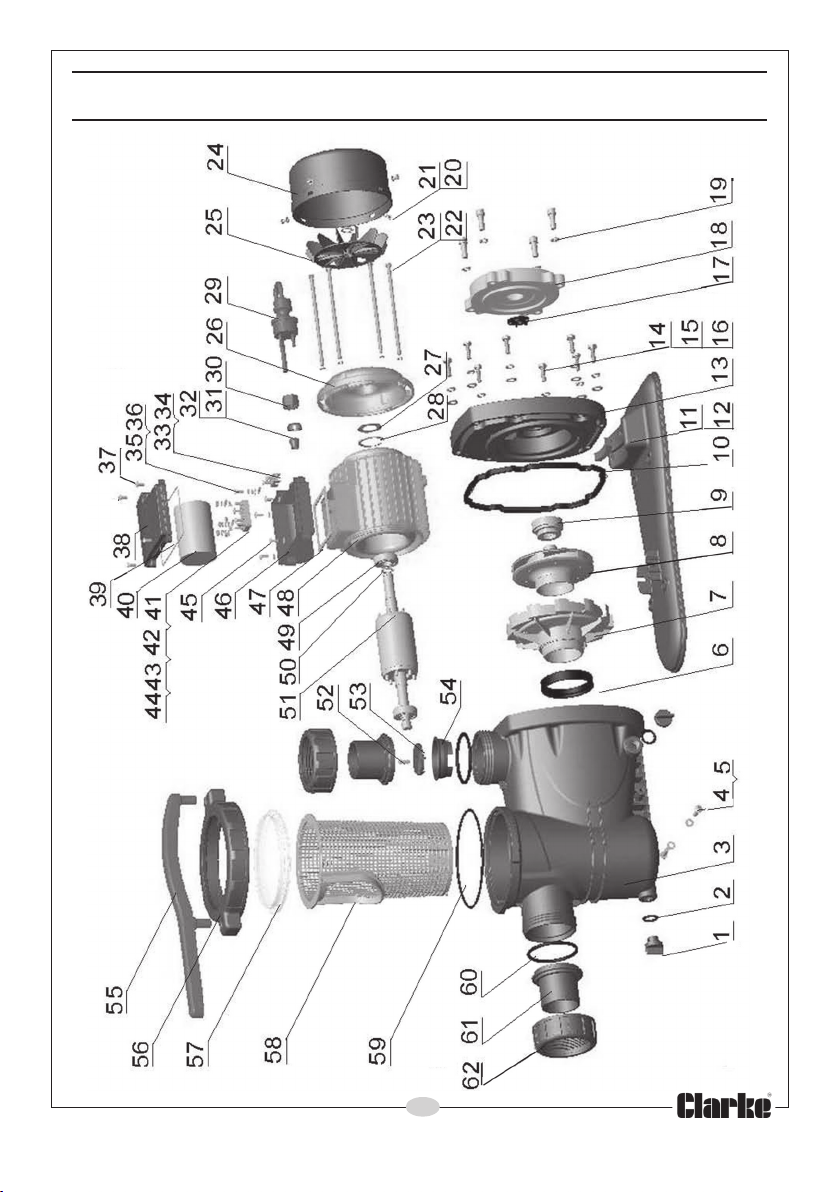
SPARE PARTS
When requesting spare/replacement parts for these pumps from CLARKE
Parts & Service, please quote the prefix ‘ZG’ followed by the model number
(SPP07, SPP10 or SPP15) and the item number from the following list/diagram
on pages 12 & 13.
ACCESSORIES
A wide range of accessories is available, including Filters, Hoses and clips,
Couplings and 90
information. The use of parts other than genuine Clarke replacement parts
may result in possible safety hazards or decreased machine performance,
and will invalidate your warranty
Parts & Service: 020 8988 7400/E-mail:[email protected] or [email protected]
° Hose Adaptors, etc. Contact your Clarke dealer for further
11
Page 12
PARTS LIST
oN
1
2gniR-OgnilaeS233pilCelbaC1
3
4
5
6
7
8
9
01
11etalPesaB124tuN6
21
31
41
51
61
71
81
91tloBdaeHtekcoS405p
02rehsaW415rotoRrotoM1
12wercSenihcaMdH-X425wercSenihcaMdH-X1
22rehsaW435evlaVpalF1
32tloBeiT445ydoBevlaV1
42revoCnaF155hcn
52naF165gniRgniniateR1
62etalPdnE175gniRgnilaeS1
72rehsaWgnirpS185retliFeveiS1
82pilcriC195gniR-O1
92elbaCrewoP106gniR-O2
W116rotcennoC2
03rehsa
13teksaG126gniRgniruceS2
Parts & Service: 020 8988 7400/E-mail:[email protected] or [email protected]
noitpircseD
gulPniarD223htaehSdelaeS1
gnisaCpmuP143wercSenihcaMdH-X2
tloB253rehsaWevaW1
rehsaW263teksa
gniRgnilaeS173wercSfoorp-repmaT4
resuffiD183lenaPrevoC1
rellepmI193teksaG1
laeSlacinahceM104roticapaC1
teksaG114draoB
rebbuRgnitnuoM134rehsaW6
egnalFgnitnuoM144kcolBgnitcennoC6
rehsaW854wercSenihcaMdH-X6
ehsaWevaW2164xoBroticapaC1
r
tloBxeH874teksaG1
dnalGfoorpretaW184rotatSrotoM1
troppuSpmuP194gniraeB2
oN noitpircseD
ytQ
G1
lanimreT1
ilcriC1
erW1
12
ytQ
Page 13
Page 14
DECLARATION OF CONFORMITY
14
Parts & Service: 020 8988 7400/E-mail:[email protected] or [email protected]
Page 15
DECLARATION OF CONFORMITY
15
Parts & Service: 020 8988 7400/E-mail:[email protected] or [email protected]
Page 16
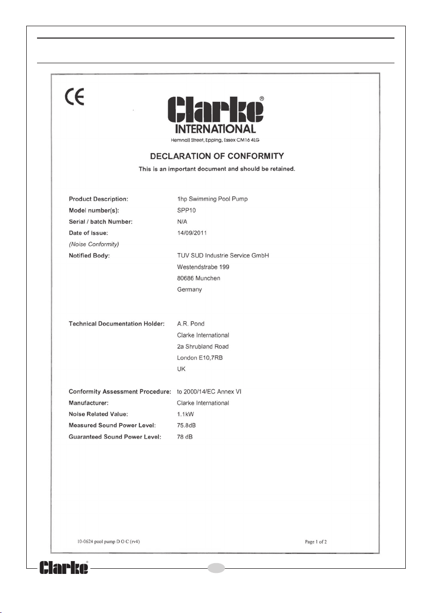
DECLARATION OF CONFORMITY
16
Parts & Service: 020 8988 7400/E-mail:[email protected] or [email protected]
Page 17
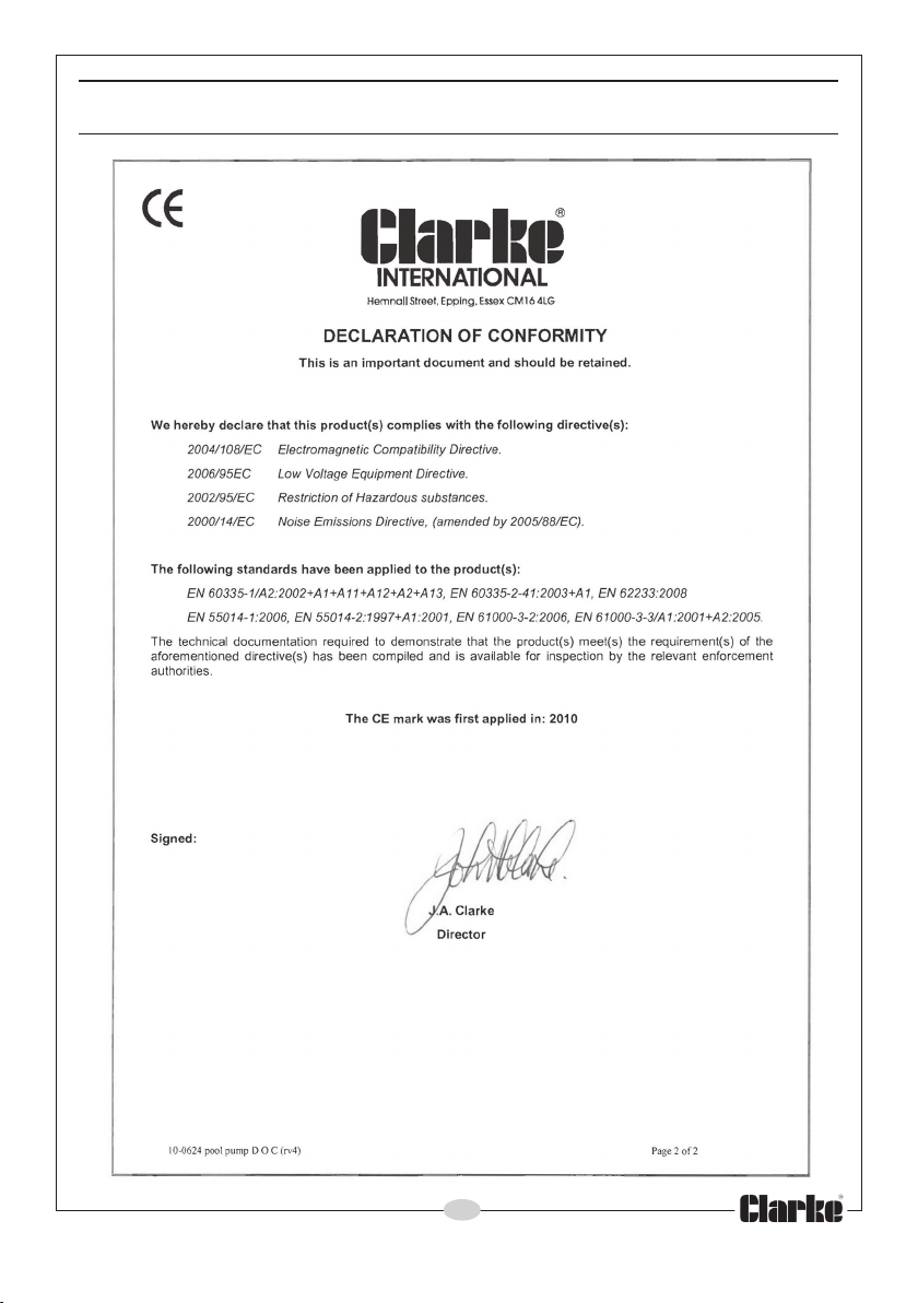
DECLARATION OF CONFORMITY
17
Parts & Service: 020 8988 7400/E-mail:[email protected] or [email protected]
Page 18
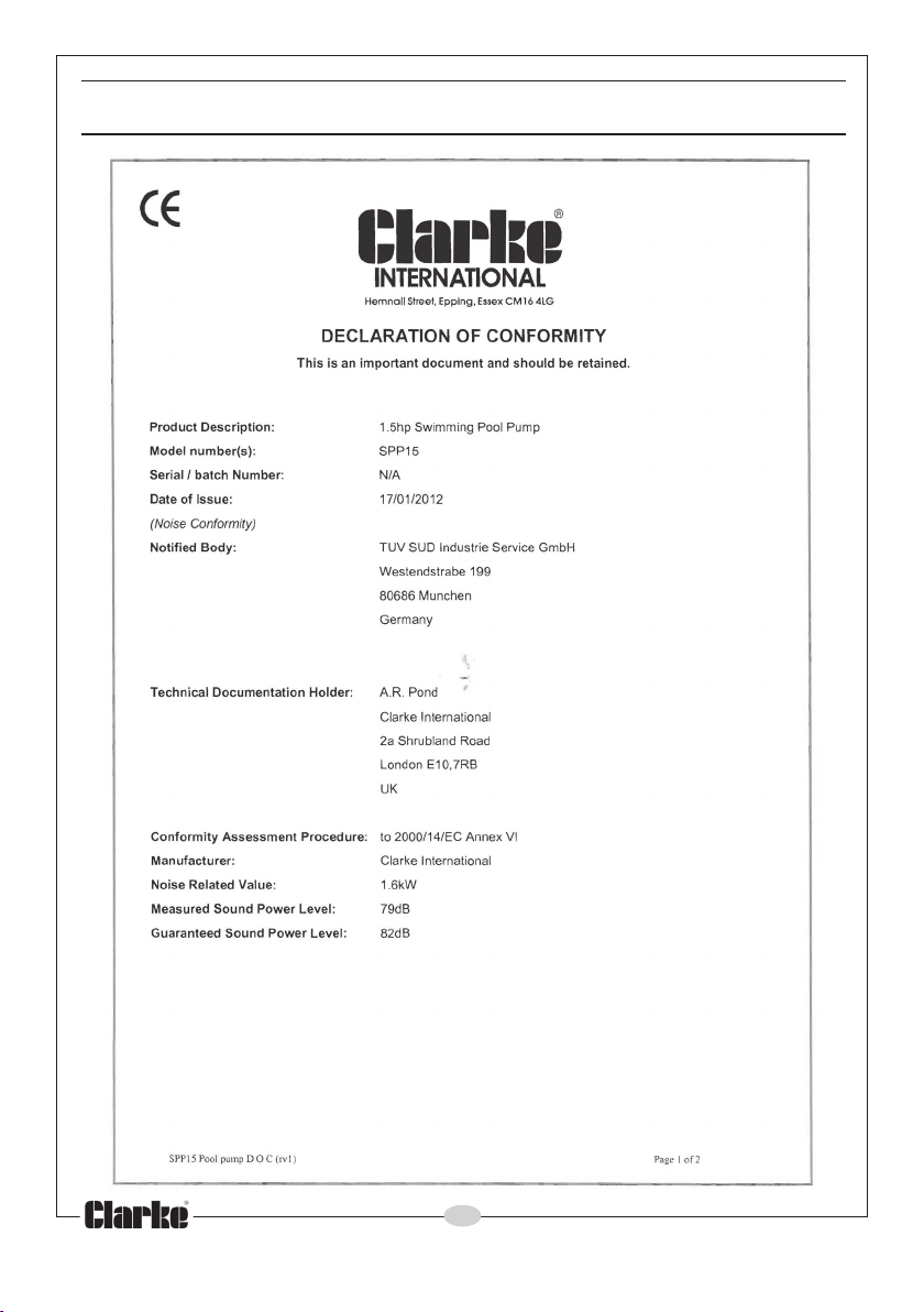
DECLARATION OF CONFORMITY
18
Parts & Service: 020 8988 7400/E-mail:[email protected] or [email protected]
Page 19
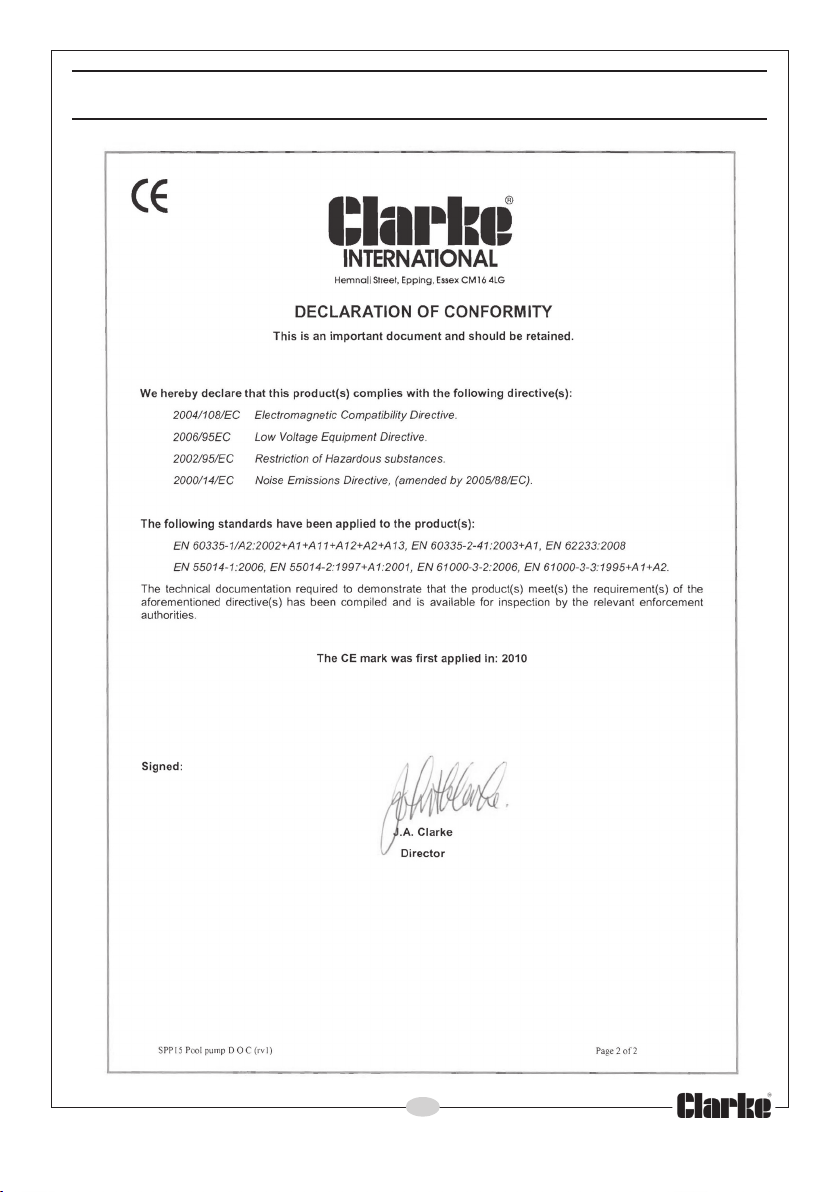
DECLARATION OF CONFORMITY
19
Parts & Service: 020 8988 7400/E-mail:[email protected] or [email protected]
Page 20

 Loading...