

Page 1
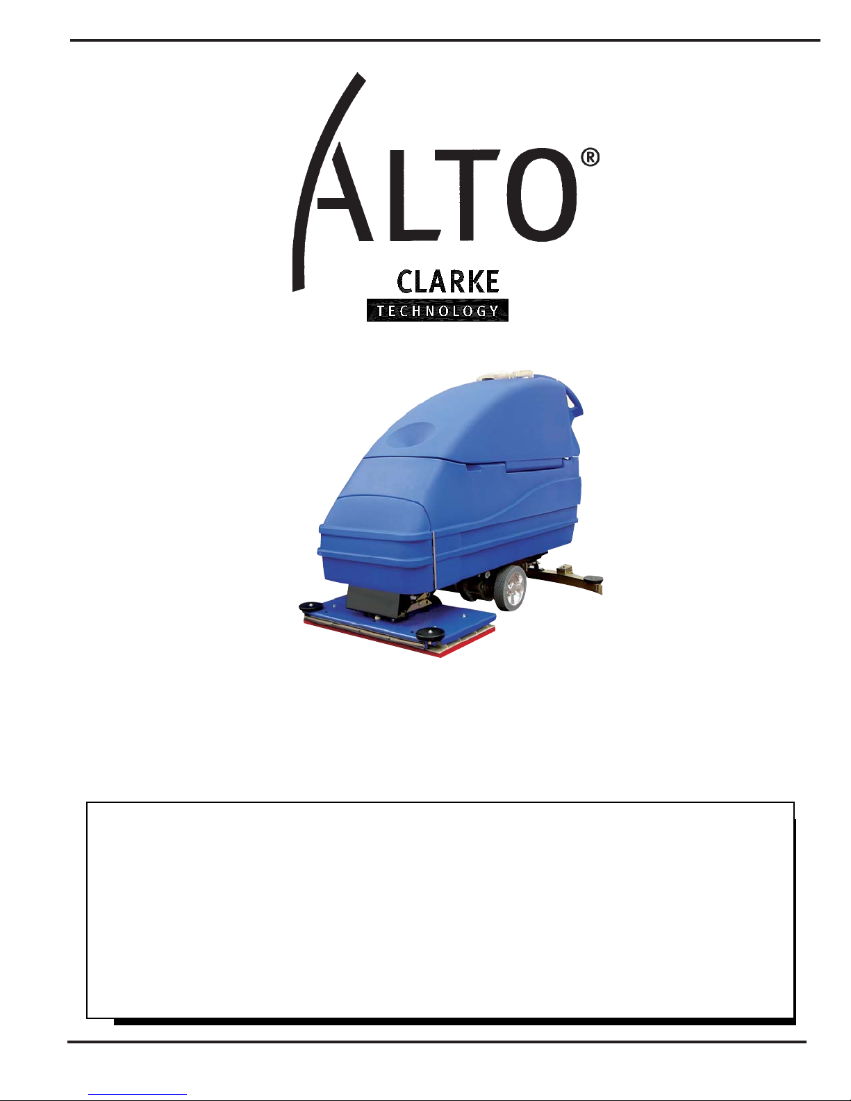
Operator's
SCRUBTEC
Manual
U.S. Patent No. 6,105,192; No. 6,557,207; No. 6,760,947; No. 5,383,251
READ THIS BOOK
This book has important information for the use and safe operation of this machine. Failure to read this book
prior to operating or attempting any service or maintenance procedure to your ALTO machine could result
in injury to you or to other personnel; damage to the machine or to other property could occur as well. You
must have training in the operation of this machine before using it. If your operator(s) cannot read this
manual, have it explained fully before attempting to operate this machine.
All directions given in this book are as seen from the operator’s position at the rear of the machine.
For new books write to: ALTO, 2100 Highway 265, Springdale, Arkansas 72764.
Form No. 71268A 10/06 CLARKE TECHNOLOGY Printed in the U.S.A.
BOOST 70
Page 2

Table of Contents
Operator Safety Instructions ............................................................................................................................ 3
Introduction & Machine Specifications ............................................................................................................. 5
Procedures for Transporting Machine ............................................................................................................. 6
Symbols Used on Scubtec Boost 70 ............................................................................................................... 8
Machine Control Panel ..................................................................................................................................... 10
Machine Controls and Features ...................................................................................................................... 11
How to Prepare the Machine for Operation ...................................................................................................... 12
How to Install the Batteries ................................................................................................................ 12
Battery Maintenance ........................................................................................................................... 13
How to Charge the Batteries ............................................................................................................. 14
How to Install the Brush or Pad ......................................................................................................... 15
How to Remove the Brush or Pad ..................................................................................................... 15
How to Operate the Machine ............................................................................................................................ 16
How to Operate the Squeegee .......................................................................................................... 16
Filling the Solution Tank .................................................................................................................... 16
Operating the Machine ....................................................................................................................... 17
How to Clean a Floor ......................................................................................................................... 18
Maintenance ..................................................................................................................................................... 19
Procedures Before Work is Began .................................................................................................... 19
Procedures to Perform at the End of Work ........................................................................................20
Procedures to Perform Every Week ................................................................................................... 21
Maintenance for the Squeegee .......................................................................................................... 22
How to Adjust the Squeegee ............................................................................................................. 22
How to Center or Off set Brushhead ................................................................................................. 23
Accessories ...................................................................................................................................................... 24
How to Correct Problems in the Machine ........................................................................................................ 25
SECTION II - Parts and Service Manual
Final Assembly Drawing .................................................................................................................................. 28
Parts List ............................................................................................................................................ 29
Recovery Tank Drawing ................................................................................................................................... 30
Parts List ............................................................................................................................................ 31
Solution Tank Assembly Drawing .................................................................................................................... 32
Parts List ............................................................................................................................................ 33
Rear Panel Assembly Drawing ........................................................................................................................ 34
Parts List ............................................................................................................................................ 35
Control Panel Assembly Drawing .................................................................................................................... 36
Parts List ............................................................................................................................................ 37
Squeegee Lift Assembly Drawing ................................................................................................................... 38
Parts List ............................................................................................................................................ 39
Squeegee Assembly Drawing ......................................................................................................................... 40
Parts List ............................................................................................................................................ 41
Frame Axle Assembly Drawing ........................................................................................................................ 42
Parts List ............................................................................................................................................ 43
Brush Head Assembly Drawing ...................................................................................................................... 44
Parts List ............................................................................................................................................ 45
Brake Assembly Drawing and Parts List ......................................................................................................... 46
Vacuum Motor Drawing and Parts List ............................................................................................................ 47
Transaxle Repair Parts .................................................................................................................................... 48
Connection Diagram ........................................................................................................................................ 49
Electrical Schematic ......................................................................................................................................... 50
-2- CLARKE TECHNOLOGY Operator's Manual SCRUTBTEC BOOST 70
Page 3

OPERATOR SAFETY INSTRUCTIONS
WARNING AVERTISSEMENT ADVERTENCIA
DANGER: Failure to read and observe all DANGER statements could result in
severe bodily injury or death. Read and observe all DANGER
statements found in your Owner's Manual and on your machine.
WARNING: Failure to read and observe all WARNING statements could result
in injury to you or to other personnel; property damage could
occur as well. Read and observe all WARNING statements found in
your Owner's Manual and on your machine.
CAUTION: Failure to read and observe all CAUTION statements could result in
damage to the machine or to other property. Read and observe all
CAUTION statements found in our Owner's Manual and on your
machine.
DANGER: Failure to read the Owner's Manual prior to operating or attempting any service or
maintenance procedure to your Clarke Technology machine could result in injury to
you or to other personnel; damage to the machine or to other property could occur
as well. You must have training in the operation of this machine before using it. If
you or your operator(s) cannot read English, have this manual explained fully before
attempting to operate this machine.
DANGER: Operating a machine that is not completely or fully assembled could result in injury
or property damage. Do not operate this machine unless it is completely
assembled. Inspect the machine carefully before operation.
DANGER: Machines can cause an explosion when operated near flammable materials and
vapors. Do not use this machine with or near fuels, grain dust, solvents, thinners,
or other flammable materials. This machine is not suitable for picking up hazardous
dust. Use only commercially available floor cleaning waxes intended for machine
operation.
DANGER: Lead acid batteries generate gases which can cause an explosion. Keep sparks
and flames away from batteries. Do not smoke around the machine. Charge the
batteries only in an area with good ventilation. Make sure that the AC charger plug
is unplugged from the wall receptacle before connecting or disconnecting the DC
plug to or from the battery pack.
DANGER: Working with batteries can be dangerous! Always wear eye protection and
protective clothing when working near batteries. Remove all jewelry. Do not put
tools or other metal objects across the battery terminals, or the tops of the
batteries.
DANGER: Using a charger with a damaged power cord could result in an electrocution. Do
not use the charger if the power cord is damaged.
WARNING: Operating this machine from anywhere other than the back of the machine could result in
injury or damage. Operate this machine only from the rear.
WARNING: This machine is heavy. Get assistance before attempting to transport or move it. Use
two able persons to move the machine on a ramp or incline. Always move slowly. Do
not turn the machine on a ramp. Do not use on surfaces having a gradient exceeding that
marked on the appliance. Read the "Procedures For Transporting" in this manual before
transporting as machine might topple over if not secured.
WARNING: Machines can topple over and cause injury or damage if guided over the edges of stairs or
loading docks. Stop and leave this machine only on a level surface. When you stop the
machine, put all switches into their "OFF" position. Turn the key switch "OFF" and
remove the key.
CLARKE TECHNOLOGY Operator's Manual SCRUTBTEC BOOST 70 - 3 -
Page 4
WARNING: Maintenance and repairs performed by unauthorized personnel could result in damage or
injury. Maintenance and repairs must be performed by authorized Clarke Technology
personnel only.
WARNING: Any alterations or modifications of this machine could result in damage to the machine or
injury to the operator or other bystanders. Alterations or modifications not authorized by
the manufacturer voids any and all warranties and liabilities.
WARNING: Electrical components of this machine can "short-out" if exposed to water or moisture.
Keep the electrical components of the machine dry. Wipe the machine down after each
use. This appliance is for dry use only and is not to be used or stored outdoors in wet
conditions.
WARNING: Operating a machine without observing all labels and instructional information could result
in injury or damage. Read all machine labels before attempting to operate. Make sure all
of the labels and instructional information are attached or fastened to the machine. Get
replacement labels and decals from your Clarke Technology distributor.
WARNING: Wet floor surfaces can be slippery. Water solutions or cleaning materials used with this
type of machine can leave wet areas on the floor surface. These areas can cause a
dangerous condition for the operator or other persons. Always put "Caution" signs
around/near the area you are cleaning.
WARNING: Improper discharge of waste water may damage the environment and be illegal.
The United States Environmental Protection Agency has established certain regulations
regarding discharge of waste water. City, state and national regulations regarding this
discharge may also be in effect in your area. Understand and follow the regulations in
your area. Be aware of the environment hazards of chemicals that you dispose.
WARNING: Only use the brushes provided with the appliance or those specified in the Operator's
Manual. The use of other brushes may impair safety.
CAUTION: Use of this machine to move other objects or to climb on could result in injury or damage.
Do not use this machine as a step or furniture. Do not ride on this machine.
CAUTION: Your machine warranty will be voided if anything other than genuine Clarke Technology
parts are used on your machine. Always use Clarke Technology parts for replacement.
CAUTION: This machine contains lead acid batteries. The batteries must be disposed of in an
environmentally acceptable manner.
English
Correct Disposal of This Product (Waste Electrical & Electronic Equipment)
(Applicable in the European Union and other European countries with separate
collection systems)
This marking shown on the product or its literature, indicates that it should not be disposed with
other household wastes at the end of its working life. To prevent possible harm to the
environment or human health from uncontrolled waste disposal, please separate this from other
types of wastes and recycle it responsibly to promote the sustainable reuse of material resources.
Household users should contact either the retailer where they purchased this product, or their
local government office, for details of where and how they can take this item for environmentally
safe recycling.
Business users should contact their supplier and check the terms and conditions of the purchase
contract. This product should not be mixed with other commercial wastes for disposal.
-4- CLARKE TECHNOLOGY Operator's Manual SCRUTBTEC BOOST 70
Page 5

Introduction & Machine Specifications
Clarke Technology’s newly designed Scrubtec Boost 70 automatic scrubber is efficient and superior floor
cleaning machines. It uses an orbital movement to scrub a path 28 inches wide. A squeegee wipes the
floor while the vacuum motor removes the dirty solution from the floor - all in one pass.
The machine comes complete with four - 6 volt batteries, one battery charger, a brush or a pad, and one
operator’s manual.
SPECIFICATIONS:
Model SCRUBTEC BOOST 70
Machine Power Supply 24 Volt D.C.,
(4) 6V 250 AH Deep Cycle Batteries or
(4) 6V 330 AH Deep Cycle Batteries
Pad or Brush 1 per Machine
Traverse 0.5 hp (0.4 kW) Transaxle
Traverse Forward Speed Variable to 250 ft./min (76 m/min)
Traverse Reverse Speed Variable to 190 ft./min. (58 m/min)
Battery Protection Low Voltage
Motor Vacuum 3/4 HP, 3 stage, Acoustical High Efficient Tangential
Solution Tank 20 Gallons (76 liters)
Solution Level Calibrated level indicator on rear of machine
Recovery Tank 20 Gallons (76 liters)
Recovery Full Indicator Electric Shut-Off
Parabolic Squeegee Swing type with breakaway feature, No tool operation feature
Squeegee Operation Reverse direction on floor and 3 - position manual lever style operation
Cleaning Swath 28 inches (71 cm)
Motor, Brush 3/4 hp (0.56 KW)
Brush / Pad Size 14" x 28" (35.6 cm x 71 cm)
Brush Speed 2250 RPM
Brush Pressure 100 lbs. (45.4 kg)
Drive Wheels (2) 8 in. x 2 in. (20 cm x 5 cm) Neoprene tread
Caster Dual 4 in. x 2 in. (10 cm x 5 cm)
Charger 24 V D.C., 25 Amp, 115/60, on-board optional
Grade Cleaning 5 Degree (6%)
Length 56.25 inches (143 cm)
Width 28.75 inches (73 cm)
Height 43 inches (109 cm)
Weight w/batteries (250 AH) 586 lbs. (266 kg)
Line of Sight (from Operator
Height): 68 inches (173 cm) 7.5 feet (2.3 m)
Noise 71 dBA
Vibration < 2.5 m/s
39 inches (99 cm) hard width with 41 inches (104 cm) flex blade width.
2
CLARKE TECHNOLOGY Operator's Manual SCRUTBTEC BOOST 70 - 5 -
Page 6
Procedures For Transporting
How to Put the Machine Into a Van or Truck
WARNING: This machine is heavy. Get
assistance before attempting
to transport or move it. Use
two able persons to move the
machine on a ramp or
incline. Always move slowly.
Do not turn the machine on a
ramp. Do not stop and leave
the machine on a ramp or
incline. The loading ramp
must be a minimum of 32"
wide.
WARNING: Machines can topple over if
guided over the edges of
stairs or loading docks and
cause injury or damage.
Stop and leave this machine
only on a level surface.
When you stop the machine,
put all switches into their
"OFF" position.
Figure #1
1. Make sure the loading ramp is at least eight
(8) feet (2.5m) long and a minimum of 32" (0.8m)
wide, and strong enough to support the machine.
2. Make sure the ramp is clean and dry.
3. Put the ramp in position.
4. Remove squeegee assembly before loading.
ALTO recommends that both the solution tank
and recovery tank are empty before loading.
5. Turn key switch "ON".
6. Align the machine on a level surface five (5) feet
(2 m) in front of the ramp.
7. Put the traverse knob at full speed.
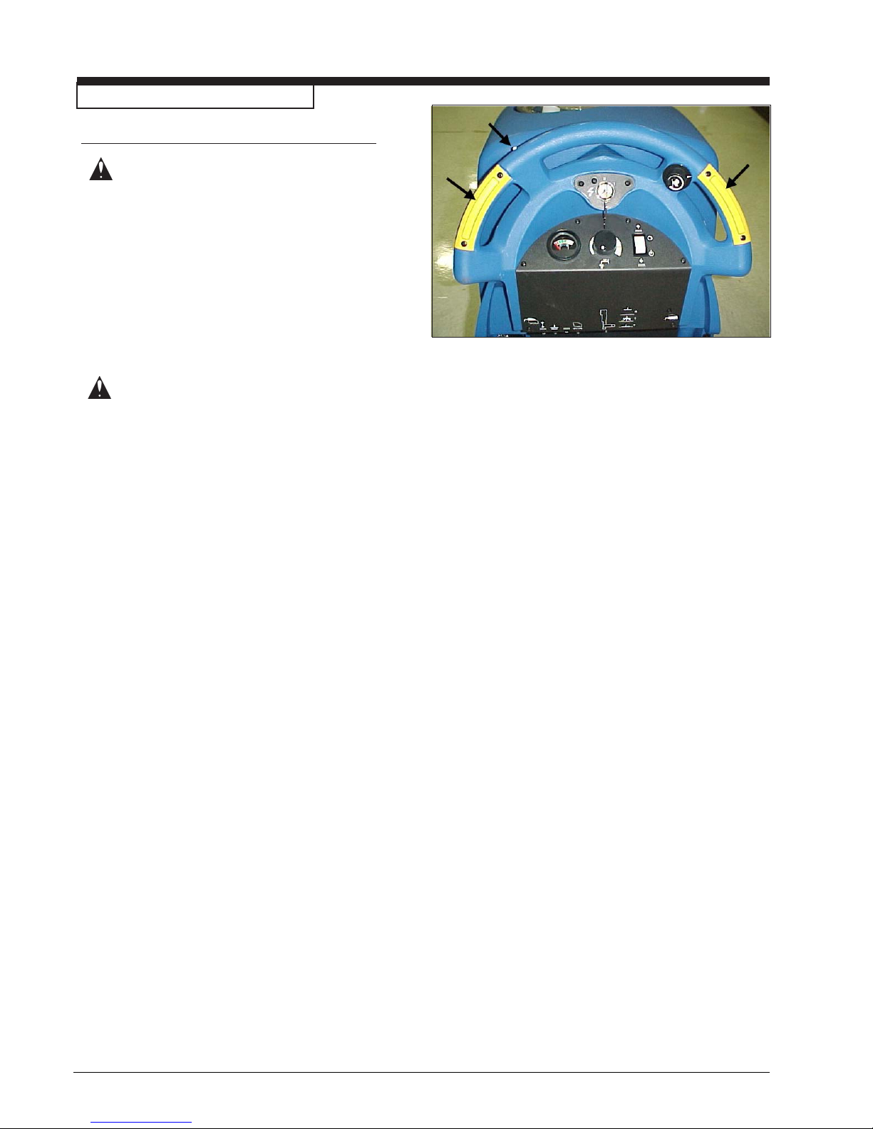
8. Push in either one of the forward/reverse
switches while pushing in the white reverse
switch. Back the machine up the ramp. See
figure 1.
9. Turn the key switch "OFF".
-6- CLARKE TECHNOLOGY Operator's Manual SCRUTBTEC BOOST 70
Page 7
Procedures For Transpoting (cont.)
10. Fasten the machine to the vehicle. Clarke
Technology recommends a strap over the top of
the machine and a strap to keep the machine
from rolling forward or backwards. If this is not
done, there is a possibility of the machine
toppling over. Four tie down points (2 along
each side of frame) are provided on machine for
securing machine.
How to Remove the Machine From a Van or
Truck
1. Make sure there are no obstructions in the area.
2. Make sure the unloading ramp is at least eight
(8) feet (2.5m) long and a minimum of 32"
(0.8m) wide, and strong enough to support the
machine.
3. Make sure the ramp is clean and dry.
4. Put the ramp in position.
Figure #2
5. Unfasten the machine.
WARNING: The machine is heavy.
Make sure you use two able
persons to assist in moving
the machine down the
ramp.
6. Turn the key switch "ON".
7. Set the traverse center knob to the slowest
forward speed setting. Carefully and slowly,
drive the machine to the top of the ramp and
start down.
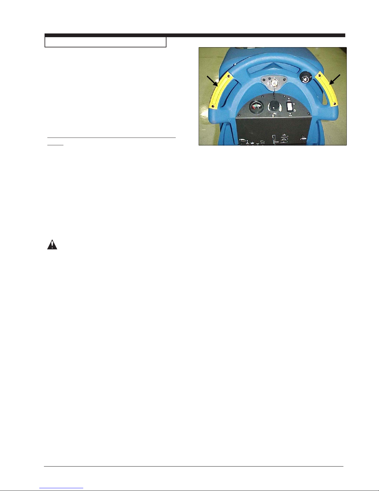
8. While pushing in the right or left forward/reverse
switch the machine will go forward. See figure
2.
9. As the machine begins to travel down the ramp,
push in the forward/reverse switch to maintain a
slow downward speed.
10. Replace squeegee assembly, brush housing,
and brush or pad driver after machine is
unloaded and ready to use.
CLARKE TECHNOLOGY Operator's Manual SCRUTBTEC BOOST 70 - 7 -
Page 8
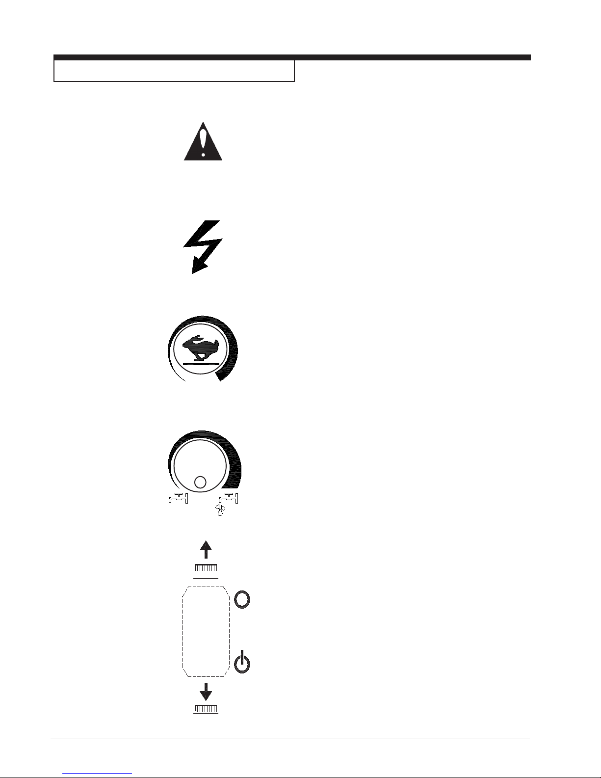
SYMBOLS USED SCRUBTEC BOOST 70
Warning
Power
Traverse Speed Control
Solution Control
Brush Up / Down
-8- CLARKE TECHNOLOGY Operator's Manual SCRUTBTEC BOOST 70
Page 9
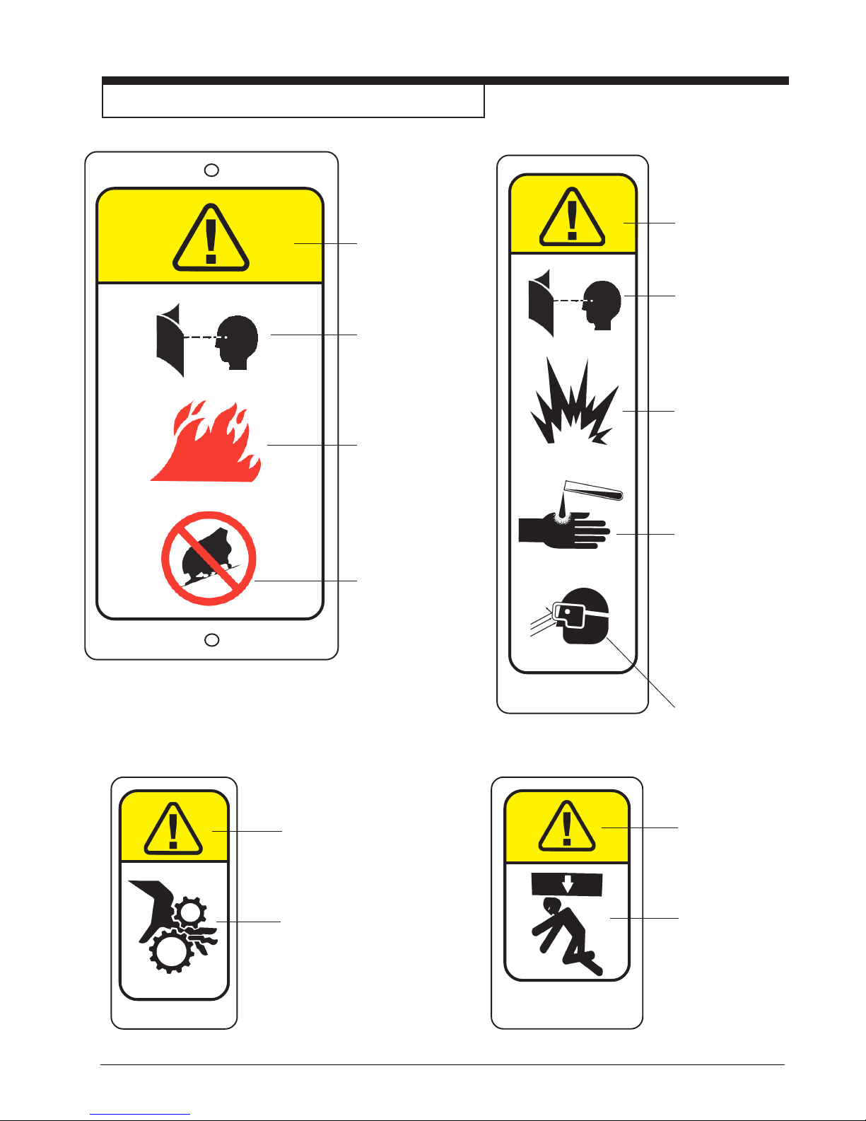
SYMBOLS USED ON SCRUBTEC BOOST 70
WARNING
READ OPERATOR'S
MANUAL BEFORE
OPERATING THIS
MACHINE
RISK OF FIRE
• Use only
commercially
available floor
cleaners and
waxes intended
for machine
operation.
• Do not use
flammable
materials.
RISK OF INJURY
OR DAMAGE TO
MACHINE
• Do not turn, stop
71018A
or leave machine
on a ramp or dock.
71015A
WARNING
READ OPERATOR'S
MANUAL BEFORE
OPERATING THIS
MACHINE
EXPLOSIVE GASES,
CAN CAUSE SEVERE
INJURY, DEATH
OR DAMAGE
TRANSFORMER.
• Keep flammable
materials away from
batteries. Charge in
a cool well ventilated
area.
BATTERIES
CONTAIN SULFURIC
ACID. CAN CAUSE
SEVERE INJURY.
• Avoid contact with
skin eyes, or
clothing. If contact,
flush with water.
Get medical
attention. If internal.
contact call physician.
WEAR
PROTECTIVE
EYE GEAR.
WARNING
MOVING PARTS.
CONTACT CAN
CAUSE SEVERE
INJURY.
• Do not place
hands or feet under
71017A
CLARKE TECHNOLOGY Operator's Manual SCRUTBTEC BOOST 70 - 9 -
machine when in
use.
WARNING
FALLING PARTS
CAN CAUSE
SEVERE INJURY.
• Make sure tank is
secure before
servicing.
71014A
Page 10
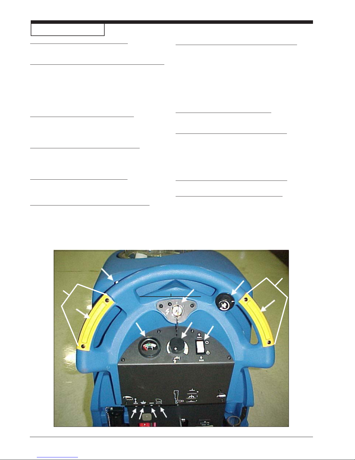
Machine Control Panel
Key Switch (See Figure 3, Item "A")
The key switch turns "ON" the power to the control
panel. "O" is "OFF" and "I" is "ON".
Forward Reverse Switch (See Figure 3, Item "B")
The forward/reverse switch turns the traverse motor
"on" forward and if the brush motors are in the down
position, activates the brush motors/solution control
module. There is a two second delay for the pad
motor to stop after releasing the switch. Either the
right or the left switch can be used. Use either switch
in conjunction with the white reverse switch to reverse
the traverse motor.
Battery Meter (See Figure 3, Item "C")
The battery meter indicates the relative charge on the
battery pack. Do not continue to run the machine
when the needle is in the "red" area. This will shorten
the life of the battery pack.
Reverse Switch (See Figure 3, Item "D")
The reverse switch, when used in conjunction with one
of the forward/reverse switches, causes the machine to
reverse directions. The reverse speed is 70% of the
forward speed.
Hour Meter (Not Illustrated) (Option)
The hour meter indicates the number of hours the
machine has operated. It runs only when the brush
motor is on.
Vacuum Motor Switch (See Figures 4 & 5, pg. 11)
To activate vacuum motor, lower squeegee handle.
Handle has two positions. Lowest position is operating
position and the middle position is transport to clear
vacuum hose.
Circuit Breakers
The circuit breaker reset buttons are located on the rear
cover. The breakers are located as follows:
Item E - Actuator Head (5 amp)
Item F - Vacuum Motor (30 amp)
Item G - Brush Motor (40 amp)
Item H - Traverse Motor (25 amp)
If a circuit breaker trips, determine which motor is not
operating and turn the key switch "OFF". Wait five minutes
and push the reset button back in. Turn the key switch
"ON" and try again. An authorized service person should
be contacted if the breaker trips again.
Control Handles (See Figure 3, Item "I")
The control handles are located at the rear of the machine. They are used to guide the machine.
Solution Control Knob (See Figure 3, Item "J")
The solution control knob regulates the flow of chemical
solution to the floor. To increase the flow, turn knob
clockwise. To decrease the flow, turn counter clockwise.
Full counter clockwise is OFF and full clockwise is ON.
Clarke Technology recommends starting with the knob
set in the green section to provide the best general
cleaning with optimal water usage.
Traverse Speed Knob (See Figure 3, Item "K")
To increase speed, turn knob clockwise.
Brush Motor Switch (See Figure 3, Item "L")
To activate brush motor, push brush position switch to
down position. Brush Motor and solution flow will activate
when the traverse buttons are pushed. To shut brush
motor off, place brush position switch in up position.
(See Fig 3, Items "E", "F", "G" & "H")
D
K
I
K
A
I
B
B
C
F
E
-10- CLARKE TECHNOLOGY Operator's Manual SCRUTBTEC BOOST 70
GH
Figure 3
J
L
Page 11
Machine Controls and Features
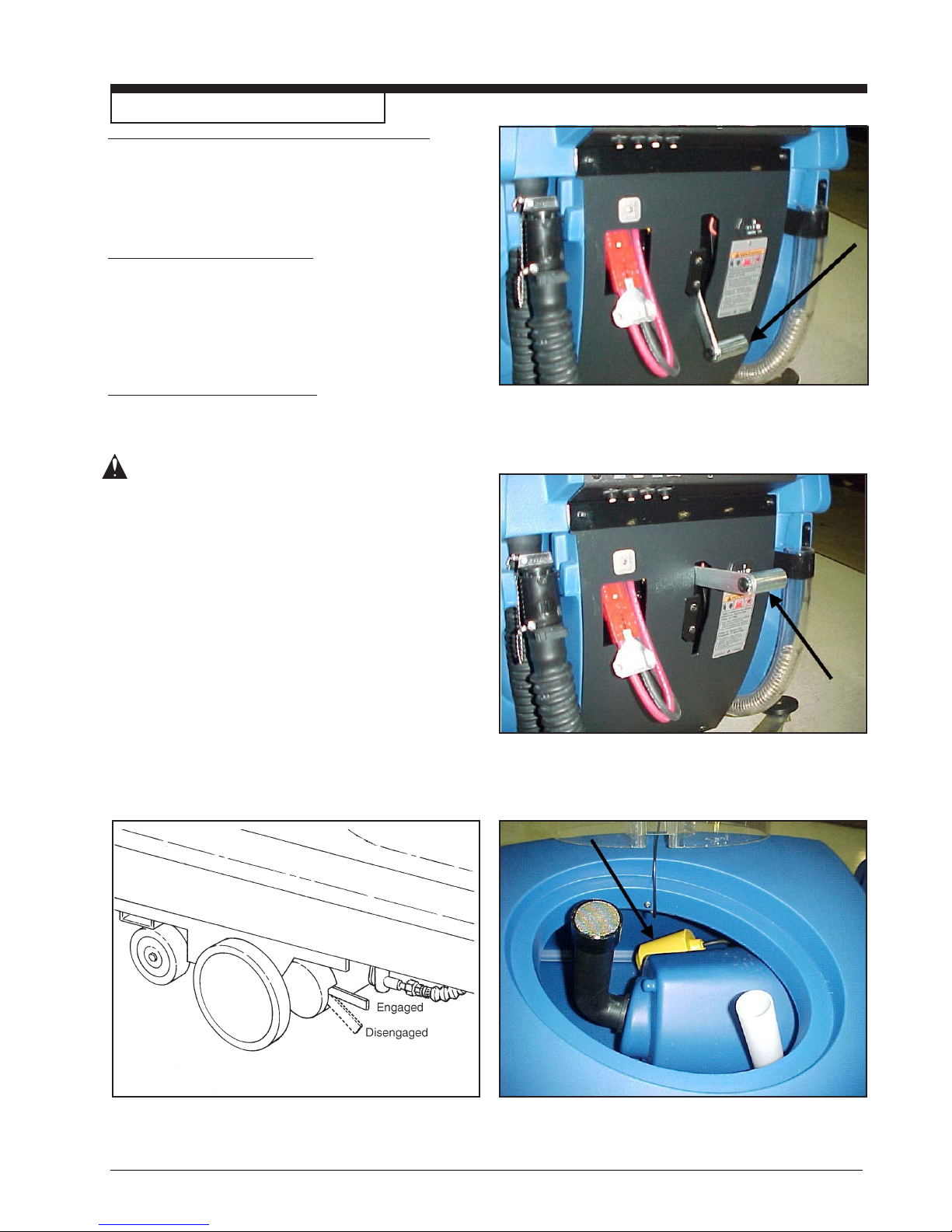
Squeegee Lift Handle, See Figures 4 and 5
The squeegee lift handle is located below the control
handles in the center. It is used to raise or lower the
squeegee. The vac motor is turned on when the
handle is lowered to either the first or last position.
Float Shut Off, See Figure 6
The shut-off switch for the vac motor is located in the
recovery tank. It automatically turns off the vac motor
when the recovery tank is full. NOTE: If excessive
foaming occurs in recovery tank, defoamer must
be added. Damage to vacuum motor could result
from foam.
Parking Brake ,See Figure 7
NOTE: Parking Brake must be used if operating
machine on greater than 2% gradient.
The parking brake prevents movement of the machine.
CAUTION: Do not activate the parking brake
while the machine is moving.
The brake is located on the right hand side of the
machine on the transaxle motor. Turn the key
switch off or disconnect the power to the battery to
apply the brake.
There is a mechanical lever located on the brake.
This lever is an override. To manually release the
brake, rotate the lever clockwise. To return the
brake to normal or to apply the brake, rotate the
lever up counter clockwise.
NOTE: If the lever is left in the override
position, the brake will not function with the
key switch, and the machine will not operate.
Figure 4
Figure 5
Figure 7
CLARKE TECHNOLOGY Operator's Manual SCRUTBTEC BOOST 70 - 11 -
Figure 6
Page 12
How To Prepare the Machine For Operation
How To Install The Batteries
The Scrubtec Boost machine uses four - 6 volt batteries.
The batteries are located in the battery compartment
under the recovery tank.
To install the batteries, follow this procedure:
1. Turn machine off. Set brake (if equipped).
2. Make sure recovery tank is empty.
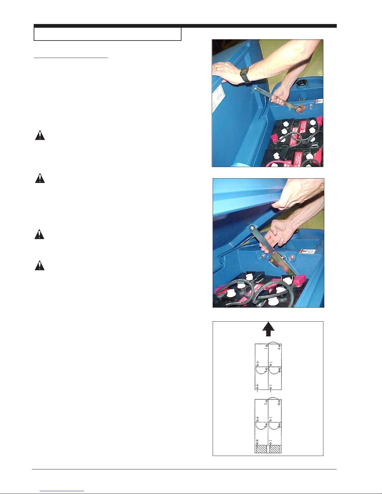
3. Tip up the recovery tank until it locks in the full open
position. See figure 8A.
CAUTION: Before raising the tank, be sure
tank is empty.
NOTE: There is an intermediate position available
for holding the recovery tank open for charging
batteries. See figure 8B.
WARNING: Do not operate or perform mainte-
nance on the machine while the
recovery tank is in the intermediate
position. The tank can be accidentally bumped and it may slam shut.
4. Place the batteries in the tray as shown in
figure 8C.
WARNING: The batteries are heavy. Lifting
batteries without help could result in
an injury. Get help to lift the batteries.
WARNING: Working with batteries can be
dangerous. Always wear eye
protection and protective clothing
when working near batteries. NO
SMOKING!
5. Connect the cables between batteries and install
long battery cable assembly as indicated. See
figure 9.
Figure 8A
Figure 8B
6. Join the connector from the battery pack to the
connector on the control panel.
7. Close recovery tank by pulling up on the latch arm
and then slowly lowering the tank.
NOTE: Charge the batteries before using the
machine.
-12- CLARKE TECHNOLOGY Operator's Manual SCRUTBTEC BOOST 70
Figure 9
Page 13
How To Prepare the Machine For Operation
Battery Maintenance
The electrical power to operate the machine comes
from the storage batteries. Storage batteries need
preventative maintenance.
WARNING: Working with batteries can
be dangerous. Always wear
eye protection and protective
clothing when working near
batteries. NO SMOKING!
To maintain the batteries in good condition, follow
these instructions:
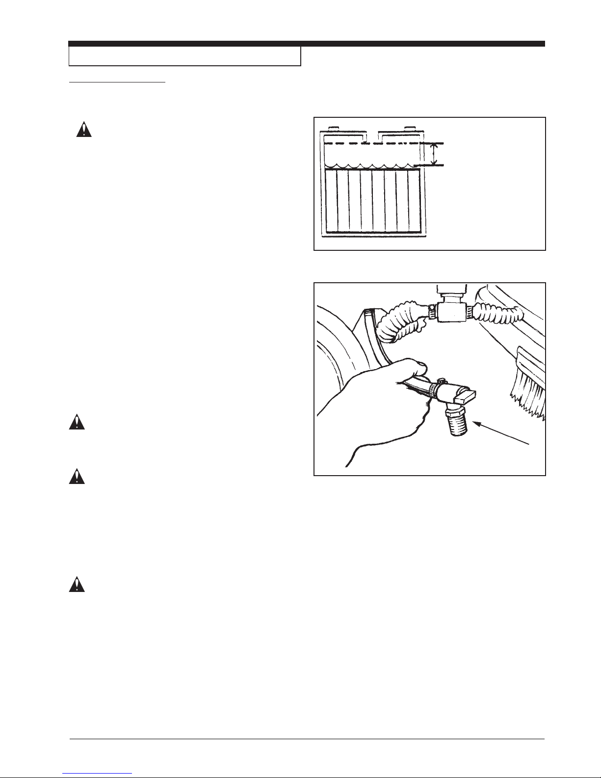
1. Keep the electrolyte at the correct level. The
correct level is between 1/4" (1/2 cm) below the
bottom of the tube in each cell and above the
tops of the plates. Check the level of the electrolyte each time you charge the batteries. See
figure 10.
NOTE: Check the level of electrolyte prior to charging
the batteries. Be sure the plates in each cell are
covered with electrolyte before charging. Do not top
off the cells prior to charging the battery. Electrolyte
expands during charging. As a result, the electrolyte
could overflow from the cells. Always top off the cells
with distilled water after charging.
Correct Level
Figure 10
CAUTION: Irreversible damage will occur to
the batteries if electrolyte does
not cover the plates. Keep the
electrolyte at the correct level.
CAUTION: Machine damage and discharge
across the tops of the batteries
can occur if the batteries are over
filled. Do not fill the batteries up
to the bottom of the tube in each
cell. Wipe any acid from the
machine or the tops of the batteries. Never add acid to a battery
after installation.
CAUTION: Batteries must be refilled with
distilled water only. Do not use
tap water as it may contain
contaminants that will damage
batteries.
2. Keep the tops of the batteries clean and dry.
Keep the terminals and connectors clean. To
clean the top of the batteries, use a damp cloth
with a weak solution of ammonia or bicarbonate
of soda solution. To clean the terminals and
connectors, use a terminal and connector
cleaning tool. Do not allow ammonia or bicarbonate of soda to get into batteries.
Figure 11
3. Keep the batteries charged.
4. To drain battery compartment: (See figure 11)
a. Always wear protective eye protection and
protective clothing.
b. Add a weak solution of ammonia or bicarbon-
ate of soda solution to battery compartment to
neutralize any spilled acid.
c. Pull drain hose out from under transaxle.
d. Place hand behind flange and open valve.
e. When empty, close valve.
f. Replace valve and drain hose on top of
transaxle.
g. Neutralize any acid spills with ammonia or
bicarbonate of soda.
CLARKE TECHNOLOGY Operator's Manual SCRUTBTEC BOOST 70 - 13 -
Page 14
How To Prepare the Machine For Operation
How To Charge The Batteries
WARNING: Charging the batteries in an area
without adequate ventilation
could result in an explosion. To
prevent an explosion, charge the
batteries only in an area with
good ventilation.
WARNING: Lead acid batteries generate
gases which could explode.
Keep sparks and flames away
from batteries. NO SMOKING!
To charge the batteries, follow this procedure:
1. Place the key switch is in the “OFF” position.
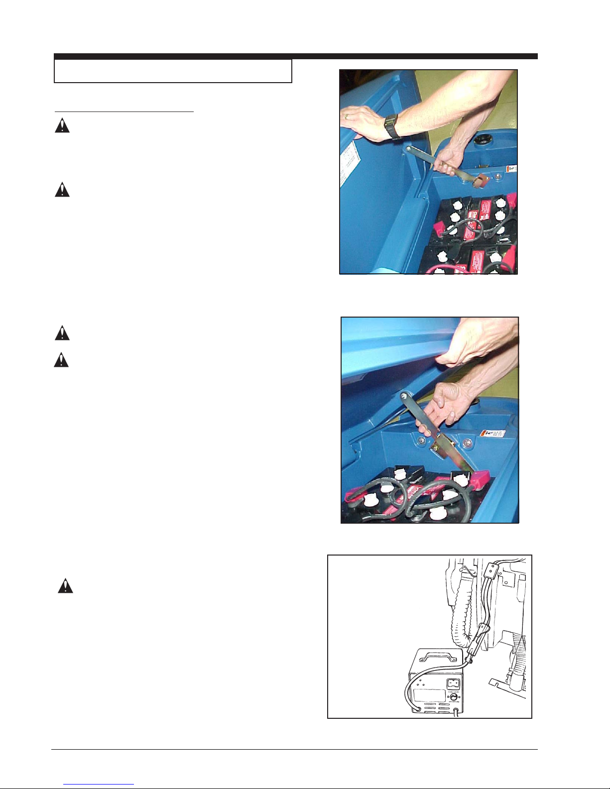
2. Before charging the batteries, the battery compartment needs to be vented. To vent compartment, tip
up the recovery tank until it locks in the open
position (see figure 12 & 13). To close the tank, pull
up on the arm and then slowly lower the tank to the
closed position.
CAUTION: Before raising tank, be sure tank
is empty.
WARNING: Do not operate or perform main-
tenance on the machine while
the recovery tank is in the open
position. The tank can be accidentally bumped and it may slam
shut.
3. Put the charger on a flat surface. Make sure the
vents on the sides are at least two inches away from
walls and other objects. Make sure there are no
objects near the vents on the bottom of the charger.
4. Disconnect the battery pack connector from the
batteries.
Figure 12
5. Connect the DC connector on the charger to the
battery pack connector. See figure 14.
6. Connect the battery charger AC cord to a minimum
15 amp 120V properly grounded wall receptacle.
NOTE: Make sure you plug into a circuit that is not
loaded by other equipment. Wall breakers may be
tripped and no charge will occur.
WARNING: Never charge a GEL battery with
an unsuitable battery charger.
Carefully follow the instructions
given by the manufacturer of the
batteries and battery charger.
NOTE: To prevent permanent damage to the batteries,
avoid their complete discharge. Never leave the batteries
completely discharged, even if the machine is not being
used. When recharging the batteries, keep the recovery
tank open. After every 20 recharging cycles, check the
level of the electrolyte and if necessary top off with
distilled water.
-14- CLARKE TECHNOLOGY Operator's Manual SCRUTBTEC BOOST 70
Figure 13
Figure 14
Page 15
How To Prepare the Machine For Operation
How To Install The Brush Or Pad
To install the brush or pad on the machine, follow this
procedure:
1. Turn the key switch "ON".
2. Put the brush switch in the "Up" position.
3. Turn the key switch "OFF".
4. Go to the front of the machine.
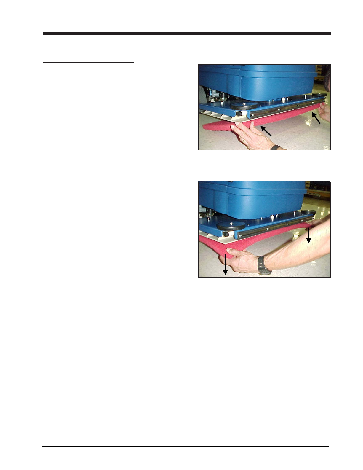
5. Press on a brush or pad, under the flex plates. See
figure 15.
NOTE: When using a black pad, position pad on head.
Lower head and operate momentarily to affix pad
to pad driver (if you have difficulty, position pad on
floor and lower head then operate.)
How To Remove The Brush Or Pad
To remove the brush or pad from the machine, follow this
procedure:
Figure 15
1. Turn the key switch "ON".
2. Put the brush switch in the "Up" position.
3. Turn the key switch "OFF".
4. Go to the front of the machine and pull downward on
the brush or pad until it releases from the flex plates.
See figure 16.
Figure 16
CLARKE TECHNOLOGY Operator's Manual SCRUTBTEC BOOST 70 - 15 -
Page 16
How To Operate The Machine
How To Operate The Squeegee
The squeegee wipes the floor while the vacuum motor
removes the dirty solution from the floor. Use your
hand to lower or raise the squeegee handle. To
operate the squeegee, follow this procedure:
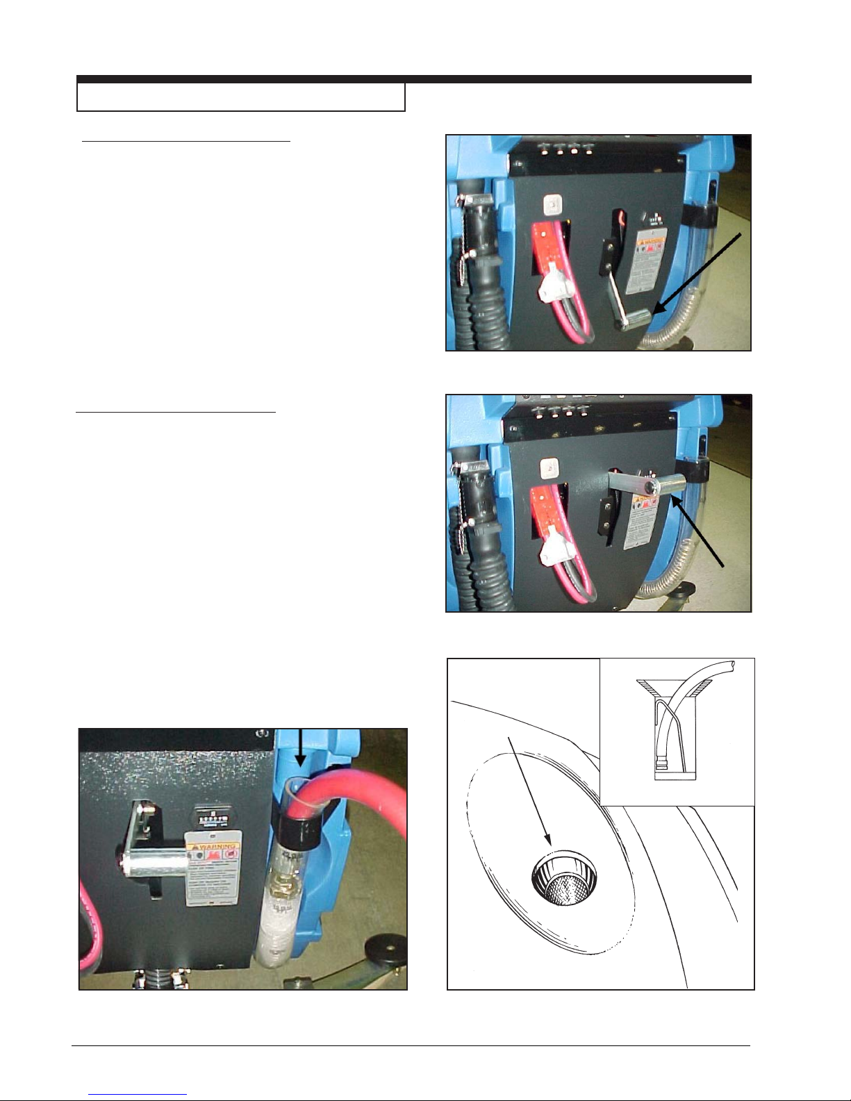
1. To lower the squeegee and start the vacuum
motor, move the squeegee lever to the right and
down. See figure 17.
2. To raise the squeegee, lift the squeegee lever up.
See figure 18.
NOTE: The center position lets the vacuum motor
continue to run with the squeegee off the floor to avoid
drips and also allows you to back up the machine.
How To Fill The Solution Tank
The solution tank can be filled in the front or through
the clear drain hose at the rear of the machine (See
figure 19). To fill the solution tank follow this procedure:
Figure 17
1. Add a cleaning chemical to the solution tank.
For the correct amount of chemical, follow the
directions shown on the container.
2. Fill the solution tank with water. When filling
machine in the front with a hose, position hose
inside the fill screen as shown in figure 19A.
When filling machine from the rear, position clear
drain hose against bracket and insert hose as
shown in figure 20 Solution level can be viewed
from the back of the machine.
Figure 18
Figure 19A
Figure 20
-16- CLARKE TECHNOLOGY Operator's Manual SCRUTBTEC BOOST 70
Figure 19
Page 17
How To Operate The Machine
WARNING: Water solutions or cleaning
materials used with this type of
machine can leave wet areas on the
floor surface. These areas can cause
a dangerous condition for the
operator or other persons. Always
put CAUTION signs near the area you
are cleaning.
WARNING: Machines can ignite flammable
materials and vapors. Do not use
with or near flammables such as
gasoline, grain dust, solvents and
thinners. Only use a cleaning
concentration recommended by the
chemical manufacturer.
WARNING: Clarke Technology recommends a
maximum water temperature of
o
F (49oC).
120
Operating The Machine
NOTE: Put the machine in the lowest traverse speed
setting. Use the machine in an area that has no furniture
or objects until you can do the following:
1. Move the machine in a straight direction, forward and
backward.
2. Stop the machine safely.
B
A
C
A
Figure 21
3. Turn the machine both left and right and return to a
straight direction.
To move the machine, follow this procedure:
1. Release the parking brake.
2. Turn the key switch to the "ON" position
3. Raise the brush to the highest setting.
4. Raise the squeegee.
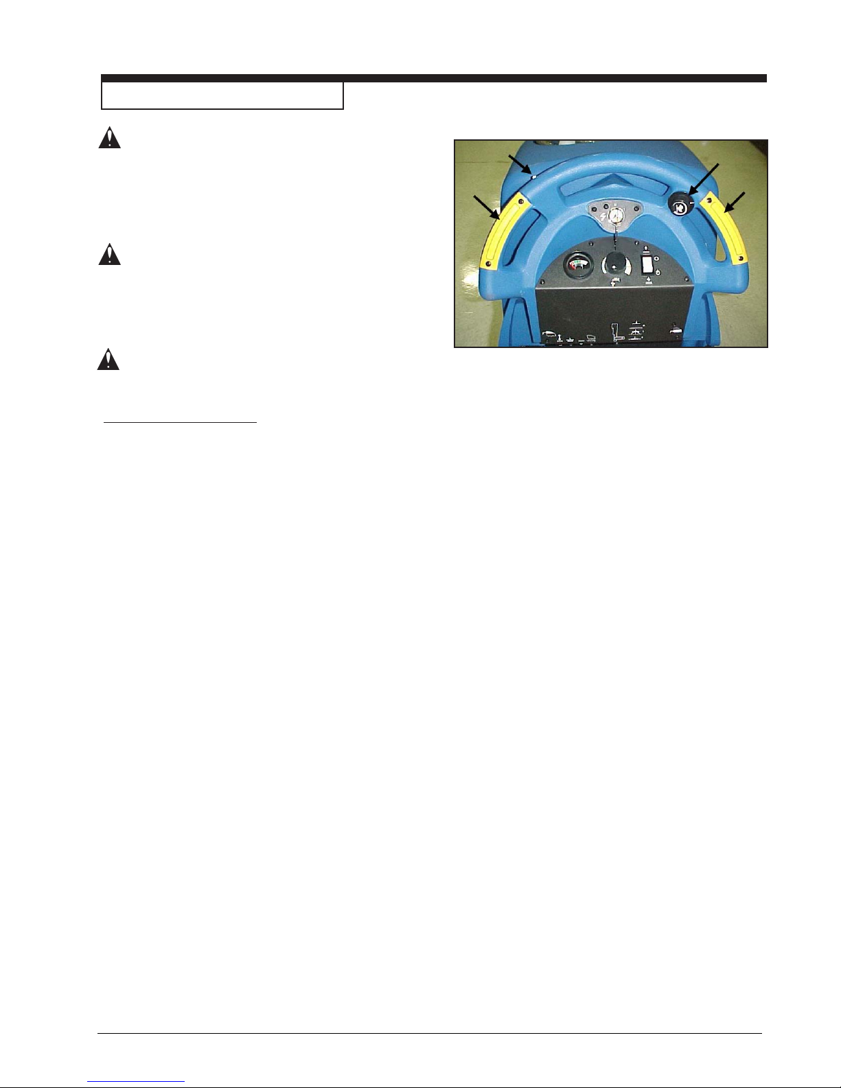
5. When either the left or right forward/reverse switches
(figure 21, item A) are pushed in, the machine will go
forward.
6. Control the speed of traverse by using the traverse
speed control knob (figure 21, Item C).
7. To stop, release the forward/reverse switch.
8. To reverse the machine, push in the white reverse
switch (figure 21 item B) and either the right or left
forward/reverse switch (figure 21 item A) at the same
time.
9. To stop, release the forward/reverse switch.
10. To turn the machine, push the rear of the machine to the
side.
11. When you stop the machine, turn the key switch
"OFF", remove the key and set the parking brake.
CLARKE TECHNOLOGY Operator's Manual SCRUTBTEC BOOST 70 - 17 -
Page 18

How To Operate The Machine (cont)
How To Clean A Floor
WARNING: Water solutions or cleaning materials
used with this type of machine can leave
wet areas on the floor surfaces. These
areas can cause a dangerous condition for
the operator or other persons. Always put
CAUTION signs near the area you are
cleaning.
To clean a floor follow this procedure:
1. Set the parking brake.
2. Put the water and a cleaning chemical in the clean
solution tank.
3. Release the parking brake.
4. Turn the key switch "ON".
5. Lower the squeegee.
6. Put the brush switch in the down position.
7. Turn the solution knob to the right to activate the flow of
solution. Adjust the flow of clean solution to the flow
desired.
8. Move the machine across the floor in the forward
direction.
9. Make a 180° turn.
NOTE: When you make more passes across the floor, let the
brush clean approximately 2 inches (5 cm) of the area already
cleaned by the brush.
NOTE: During most cleaning procedures, apply and remove
the solution in one operation.
How To Clean A Very Dirty Floor
To clean a very dirty floor, follow this procedure:
1. Apply solution to the floor.
2. Do not lower the squeegee. This will keep the vacuum
motor off.
3. Lower the brush or pad and scrub the floor.
4. Scrub the floor again with additional solution and lower
the squeegee.
5. Pick up all the solution with the squeegee.
-18- CLARKE TECHNOLOGY Operator's Manual SCRUTBTEC BOOST 70
Page 19
Maintenance
WARNING: Maintenance and repairs must be
done by authorized personnel only.
WARNING: Always empty the solution tank and
recovery tank before doing any
maintenance.
WARNING: Keep all fasteners tight.
These Maintenance Procedures Must Be Done
Every Day
Keep the machine clean, it will need fewer repairs and
have longer life.
Do These Procedures When You Begin Your Work
Period
1. Turn off key switch.
Figure 22
2. Disconnect AC power from battery charger (follow charger instructions).
3. Disconnect the plug on the battery charger from
the battery pack connector.
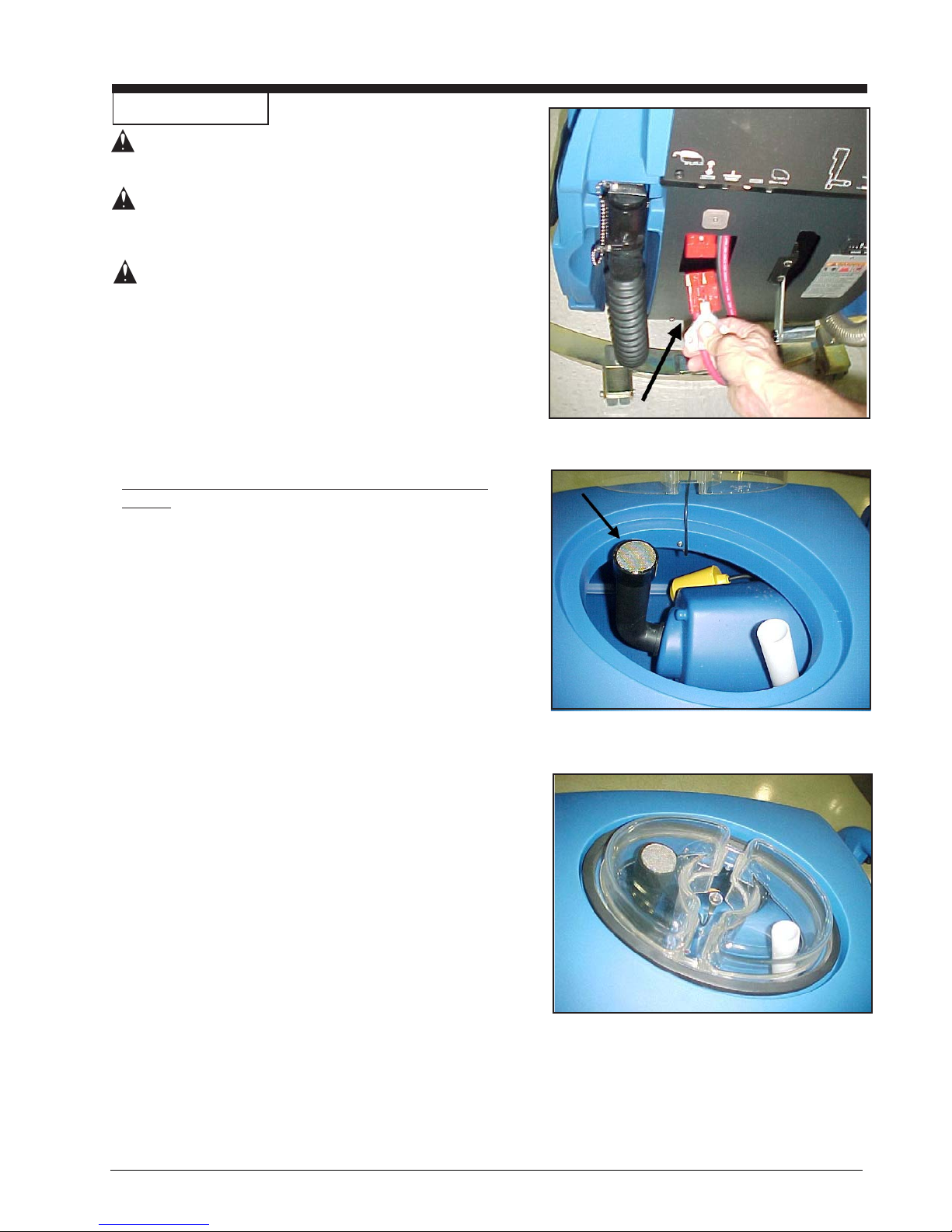
4. Join the connector from the batteries to the
control panel cable connection. See figure 22.
5. Make sure the Screen filter over the vacuum
motor is clean and in position. See figure 24.
6. Make sure the recovery tank lid is on correctly.
See figure 23, Item A.
7. Make sure the valve on the recovery drain hose is
clean. Tightly close the valve.
8. Make sure the brush or pad is in position and
installed correctly.
9. Check the installation of the squeegee and
squeegee hose.
10. Make sure the solution drain / level indicator hose
is secure on the storage mount on the rear of the
machine.
Figure 23
Figure 24
CLARKE TECHNOLOGY Operator's Manual SCRUTBTEC BOOST 70 - 19 -
Page 20
Maintenance
Do These Procedures When You End Your Work
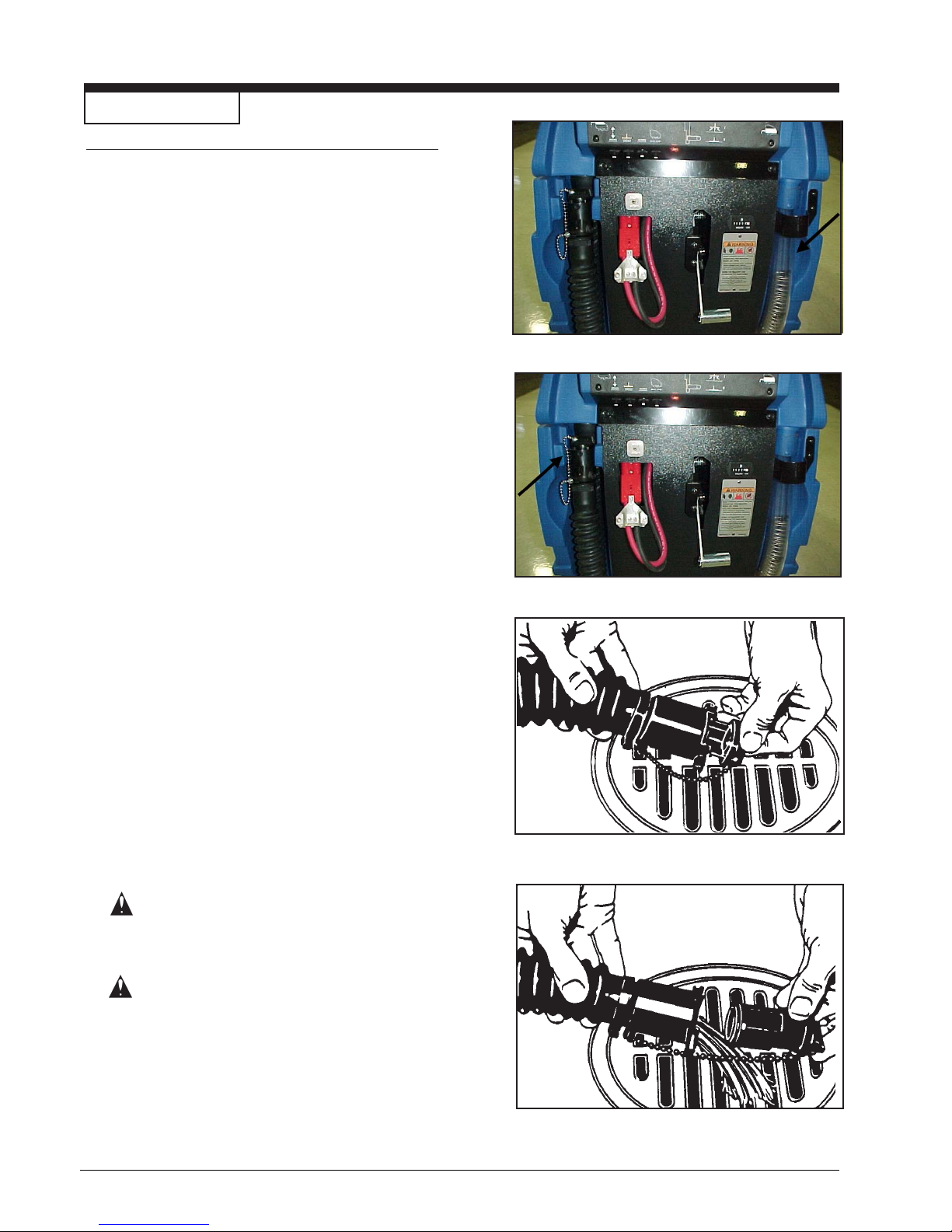
1. Drain the solution tank (Figure 25) and the recovery
tank (Figure 26). To drain the tanks , follow this
procedure:
a. Turn the key switch “OFF”.
b. Remove the drain hose from the back of the
machine.
c. Put the end of the hose over a drain or bucket.
d.
Recovery Tank:
1.) Turn the valve handle to the left. Pull the
handle out to open the drain (Figure 27).
NOTE: Have the opening in the side of the valve away
from you when you open the valve.
2.) To open the valve completely, turn the
handle to the right. Pull the handle out of
valve (Figure 28).
Solution Tank:
When hose is lowered to water level, water will
flow.
Figure 25
2. Flush the tanks. To flush the tanks, put clean water in
the tank through the opening on top of the tank.
3. If a tank or drain hose has an obstruction, use a pressure
water hose to flush the tank or hose. Put the water hose
into the drain hose.
4. Leave the tanks and the recovery drain valve open to dry
in the air.
5. Check the squeegee blade. Use a cloth to clean the
squeegee blade. If the squeegee blade is damaged or
worn, turn or replace the blade.
6. Check and clean the solution lid gasket. Use a mild
cleaning solution and rinse the parts in clean water.
Check the batteries and if necessary add distilled water
after charging. The correct level is within 1/4 inch (1/2 cm)
of the bottom of the tube in each cell.
CAUTION: Tap water may contain contami-
nants that will damage batteries.
Batteries must be refilled with
DISTILLED WATER ONLY.
WARNING: Lead acid batteries generate
gases which can cause an explosion. NO SMOKING. Always wear
eye protection and protective
clothing when working near
batteries.
Figure 26
Figure 27
Use a clean cloth and wipe the surface of the machine.
Charge the batteries. See the instruction in the section of
this book called “How To Charge The Batteries”.
-20- CLARKE TECHNOLOGY Operator's Manual SCRUTBTEC BOOST 70
Figure 28
Page 21
Maintenance
Maintenance Procedures To Be Done Every Week:
WARNING: Maintenance and repairs must be done
by authorized personnel only. Always
empty the solution tank and the
recovery tank before doing any
maintenance. Keep all fasteners tight.
WARNING: Always wear eye protection and
protective clothing when working near
batteries. Do not put tools or other
metal objects across the battery
terminals or the tops of the batteries.
CAUTION: To prevent damage to the machine, and
discharge across the tops of the
batteries, do not fill the batteries above
the bottom of the tube in each cell.
Wipe any acid from the machine or the
tops of the batteries. Do not add acid to
battery after installation.
NOTE: Always turn off key switch before servicing the
machine.
WARNING: Always wear eye protection and
protective clothing when working near
batteries. NO SMOKING!
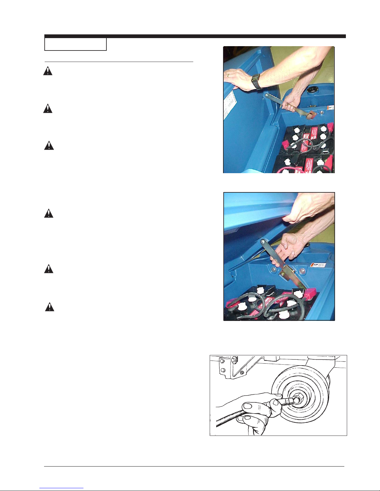
1. To inspect batteries, tip up recovery tank until it locks in
the full open position. See figure 29A. To close the tank,
pull up on the latch arm and then slowly lower the tank to
the closed position.
Figure 29A
CAUTION: Before raising the tank, be sure tank is
empty.
NOTE: There is an intermediate position available for holding
the recovery tank open for charging batteries. See figure 29B.
WARNING: Do not operate or perform
maintenance on the machine while
the recovery tank is in the
intermediate position. The tank can
be accidentally bumped and it may
slam shut.
2. Disconnect the batteries. Use a cloth and a solution of
ammonia or bicarbonate of soda to wipe the top of the
batteries. Clean the battery terminals. Reconnect the
batteries.
3. Check the hoses for leaks, obstructions and other
damage.
4. Use a grease gun to lubricate the dual casters. See figure
30.
Figure 29B
Figure 30
CLARKE TECHNOLOGY Operator's Manual SCRUTBTEC BOOST 70 - 21 -
Page 22
Maintenance
Maintenance For The Squeegee
To remove the squeegee, follow this procedure:
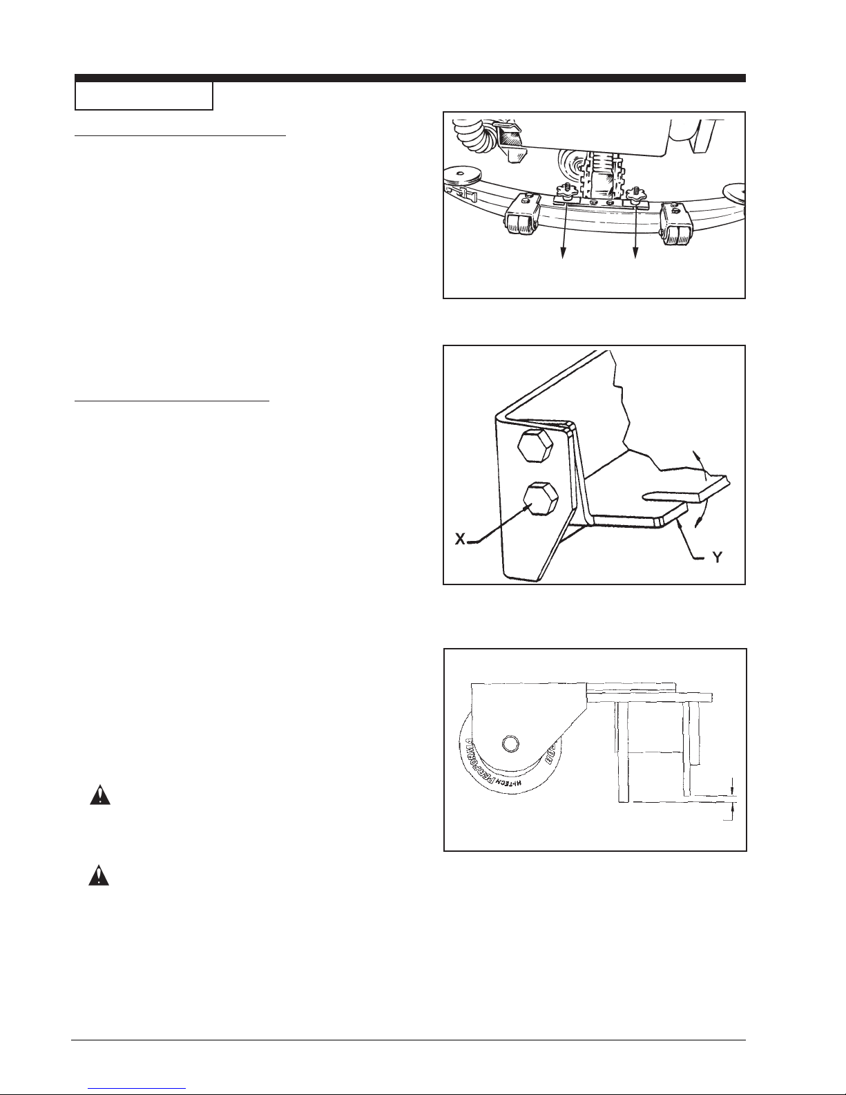
1. Remove the squeegee assembly by loosening the two
knobs that attach the squeegee to the machine. Pull
the squeegee assembly off. See figure 31.
2. Inspect the squeegee blade.
3. If the blade is worn, turn the blade so that a new edge
is in the wiping position.
4. Reinstall squeegee assembly on the machine.
How To Adjust The Squeegee
The following adjustments are set at the factory, however
they may require slight adjustment.
Adjusting Squeegee Tilt:
Figure 31
The tilt of the squeegee causes the rear blade to raise up
in the center or on the ends, depending on which
direction the tilt is changed. For tilt adjustment, refer to
figure 32. Loosen left and right screw "X". In order to
bring the blades down in the center, tip "Y" down. To
bring both ends down, tip "Y" up. Make very small
adjustments and try it until a uniform flare is achieved.
Adjusting Squeegee Blades:
When properly installed the front blade should be approximately 0.12" (3.0mm) above the rear blade. See
figure 33.
WARNING: Maintenance and repairs
must be done by authorized
personnel only .
WARNING: Electrical repairs must be
done by authorized
personnel only.
Figure 32
0.12" (3.0 mm)
Figure 33
-22- CLARKE TECHNOLOGY Operator's Manual SCRUTBTEC BOOST 70
Page 23
Maintenance cont.
Consult your Clarke Technology Authorized Service
Person to do the service procedures.
Use only genuine Clarke parts.
How to Center or Offset the Brush Head
The brush head on this machine can be centered or
offset 1 inch to the right side of the machine. To
center or offset the brush head, follow this procedure:
Recommended tools: 3/8" drive rachet, 3" extension
and 9/16" socket.
CAUTION: Before offsetting the brush head,
be sure that the recovery tank is
empty of solution.
1. Turn the key switch "ON".
2. Put the brush switch to the "Up" position.
1
2
3
4
3. Turn the key switch "OFF" and remove the key.
4. Tip up the recovery tank until it locks in the full open
position.
5. Go to the front of the machine and unlatch the front
cover and swing cover open.
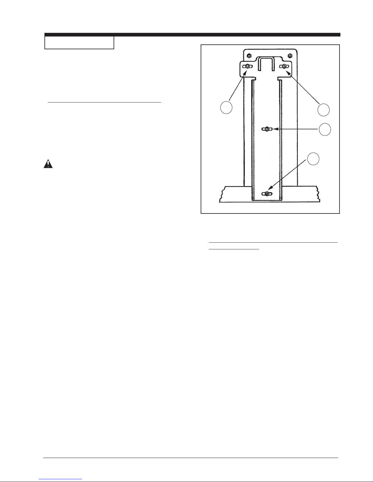
6. Locate the four mounting studs on the brush head
bracket. See figure 34. The top two mounting nuts
can be accessed through the top of the solution
tank. The lower two can be accessed through the
front. Loosen the four mounting nuts 2 to 3 turns
counterclockwise. NOTE: Do not remove mounting
nuts.
7. The brush head assembly can slide to the right side
by one inch or placed back into the center. Slide the
brush head assembly all the way to the ends of the
slots for the desired position. This insures that the
head operates straight up and down.
8. After repositioning the brush head, tighten nuts
securely to approximately 236 inch-lbs.
9. Close the front cover.
10. Close the recovery tank.
Figure 34
Maintenance Procedures That Must Be Done
Every Six Months
Contact a Clarke Technology Authorized
Service Center to perform this six month
procedure.
1. Check the carbon brushes in the electric motors.
2. Clean the battery terminals and connectors.
Make sure all of the battery connections are
tightened correctly.
3. Check all of the switches, controls, valves,
hoses and gaskets.
4. Check and remove debris from the transaxle
hubs.
5. Replace the rubber isolators (see Ref. #23 in
Brush Head Assembly Parts List section). The
rubber isolators are considered wear items and
must be replaced every 6 months.
6. Replace the rubber mounts (see Ref. #56 in
Brush Head Assembly Parts List section). The
rubber mounts are considered wear items and
must be replaced every 6 months.
CLARKE TECHNOLOGY Operator's Manual SCRUTBTEC BOOST 70 - 23 -
Page 24

ACCESSORIES
Description Part No.
Power Wand System Kit 10150A
Clarke Care Kit 14607A
39" Squeegee Assembly 11054K
Poly Dur Protectant 50478A
Kit, Grease Gun 55420A
Kit, Low Voltage Shut-Off 14097A
Brake Kit Assembly 10072A
Accessory Bag 30070A
Hour Meter Kit 10656A
Soft Caster Assembly 51092A
Kit, Solution Fill 10177A
ESP Recycle System 10663A
Accessories
Pads: Brushes:
Size Description Part No. Size Description Part No.
14 x 28 Red (5 pack) 997001 14 x 28 Poly Brush 30752A
14 x 28 Black (5 pack) 997000 14 x 28 Nylon Brush 30751A
14 x 28 White (5 pack) 997002 14 X 28 Grit Brush 30753A
14 x 28 Blue (5 pack) 997006
Squeegee Blades:
Description 39" Assembly
Blade, Rear - Linatex 30069L
Blade, Rear - Gum Rubber 30069A
Blade, Rear - Nitrile Solid 30082A
Blade, Rear - Ribbed Orange 30086A
Blade, Front - Linatex 30717L1
Blade, Front - Ribbed Natural 30091A
Blade, Front - Slit Grout 30080A
Blade, Front - Ribbed Orange 30084A
-24- CLARKE TECHNOLOGY Operator's Manual SCRUTBTEC BOOST 70
Page 25

HOW TO CORRECT PROBLEMS IN THE MACHINE
PROBLEM CAUSE ACTION
There is no solution flow.
The solution flow does not stop.
The machine does not remove all the
water from the floor.
The solution tank is empty.
The solution valve is closed.
There is an obstruction in the solution hose
or filter.
The solution valve or electric wiring is
damaged.
The solution module is defective.
The solution valve is open.
The solution valve or wiring is damaged.
The solution valve is dirty
There is a damaged seat and washer in the
solution valve.
The solution module is defective.
The squeegee is up.
The squeegee tilt is not correct.
The recovery tank is full.
The screen filter is dirty.
Fill the solution tank.
Open the solution valve.
Remove the obstruction from the hose or filter.
Repair or replace the valve or the electric
wiring.
Replace solution module
Close or Clean the solution valve.
Repair or replace the valve and the wiring.
Clean the solution valve.
Replace the seat and washer.
Replace solution module.
Lower the squeegee.
To adjust See Figure 11, page 23.
Drain the recovery tank.
Clean the screen filter.
The batteries do not give the normal
running time.
There is an obstruction or damage in the
squeegee, squeegee hose or standpipe.
The vacuum motor is not running.
The squeegee hose is disconnected, or
damaged
The squeegee blade is damaged, worn, or
incorrectly installed.
The gaskets on the cover of the recovery
tank are damaged.
The battery terminals are dirty or damaged.
The electrolyte level is too low.
The batteries are not fully charged.
The charger is damaged.
The battery is defective.
The batteries are disconnected.
Remove the obstruction or repair the damage.
Check for tripped breaker. Have an authorized
service person make repairs.
Check and connect hose.
Turn or replace the squeegee blade.
Correctly install the squeegee blade.
Replace the gaskets.
Clean the terminals and connectors. Replace
the damaged cables. Charge the batteries.
Add distilled water to each cell and charge the
batteries.
Charge the batteries for a full 16 hour charge.
Have an authorized service person repair the
charger.
Check voltage of each cell while discharging.
Connect the batteries.
CLARKE TECHNOLOGY Operator's Manual SCRUTBTEC BOOST 70 - 25 -
Brush is in heavy scrub setting.
Adjust Pressure.
Page 26

PROBLEM CAUSE ACTION
The cleaning is not even. The scrub brush or pad is worn.
There is damage to the brush assembly,
caster or the solution valve.
The brush motor is not running
The solution level is low.
The machine does not run. The machine loses power.
Key or switch is off.
Batteries are unplugged.
Battery terminals are dirty.
Batteries are discharged
Replace the scrub brush or pad.
Have an authorized service person make
the needed repairs.
Check for tripped breaker. Reset. Check
for loose connections.
Fill the solution tank.
NOTE: If the problem continues consult an
authorized service person.
Reset the circuit breaker.
Turn key or switch on.
Check the battery connections.
Check battery gauge and recharge
NOTE: If the problem continues consult an
authorized service person.
-26- CLARKE TECHNOLOGY Operator's Manual SCRUTBTEC BOOST 70
 Loading...