

Page 1
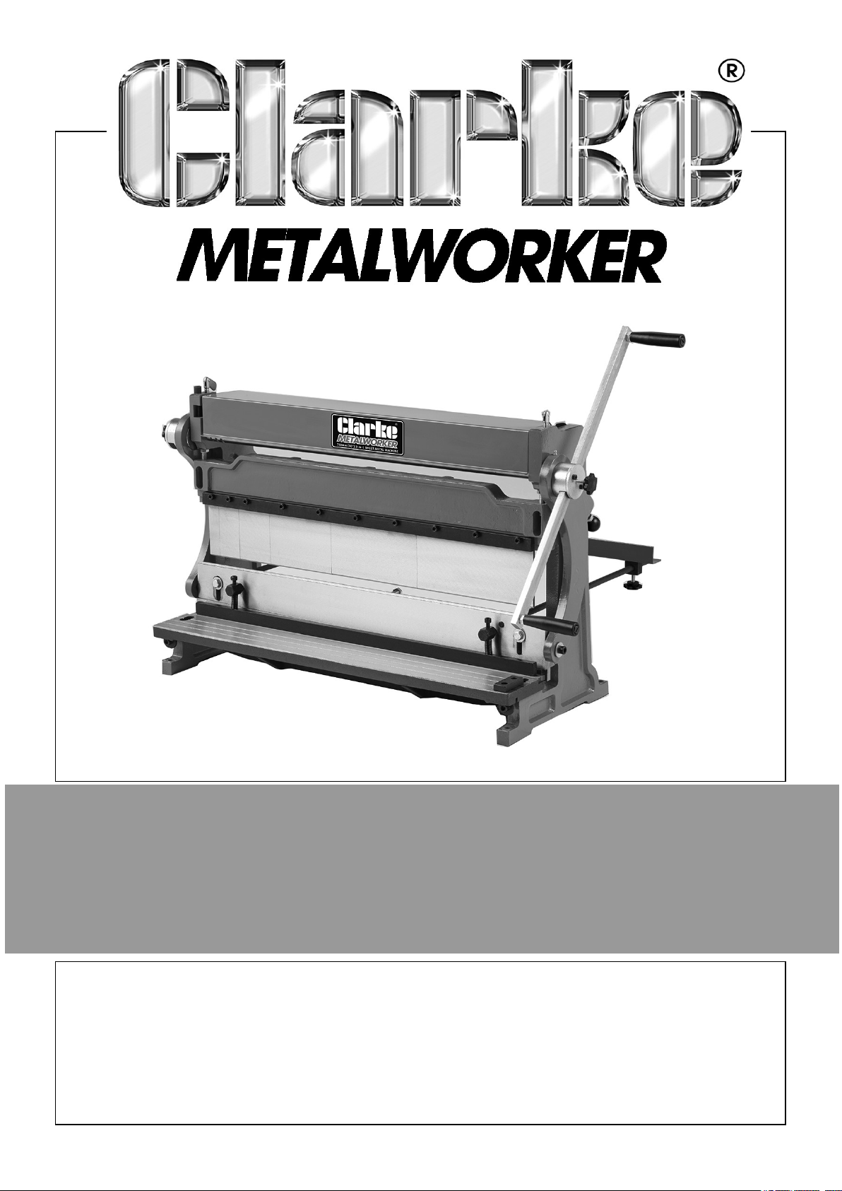
3 IN 1 SHEET METAL MACHINE
MODEL NO: SBR760B
PART NO: 6560031
OPERATING & MAINTENANCE
INSTRUCTIONS
ORIGINAL INSTRUCTIONS GC12/24
Page 2
INTRODUCTION
Thank you for purchasing this CLARKE 3 in 1 sheet metal machine.
Before attempting to use this product, please read this manual thoroughly and follow
the instructions carefully. In doing so you will ensure the safety of yourself and that of
others around you and you can look forward to your purchase giving you long and
satisfactory service.
FEATURES
• Shear Table Front Guide
• Shear & Brake Adjustable Rear Stop
• Hardened Steel Brake Fingers
• Precision Ground Hardened Steel Shear Blade
SPECIFICATIONS
Model SBR760B
Part Number 6560031
Weight. 129.9 kg
Width/Depth/Height 939 ex handle x 370 x 560 mm
Capacities:
Maximum Workpiece Width 760 mm
Maximum Workpiece Thickness 1 mm /20 gauge mild steel/
Aluminium and copper 1.2mm/
18 gauge
Pan/Box Brake Minimum Reverse Bend 9 mm
Pan/Box Brake Maximum Side Height @ 90° 105 mm
Slip Roll Minimum Cylinder Diameter 38 mm
Slip Roll Wire Sizes (L to R) 4 mm, 5 mm, 6 mm
2
Page 3
SAFETY PRECAUTIONS
WARNING: LIKE ALL MACHINERY THERE IS POTENTIAL DANGER
WHEN OPERATING THIS MACHINE. ACCIDENTS ARE FREQUENTLY
CAUSED BY LACK OF FAMILIARITY OR FAILURE TO PAY ATTENTION.
USE THIS MACHINE WITH RESPECT AND CAUTION TO DECREASE
THE RISK OF OPERATOR INJURY. IF NORMAL SAFETY
PRECAUTIONS ARE OVERLOOKED OR IGNORED, SERIOUS
PERSONAL INJURY MAY OCCUR.
To protect against serious injury, use common sense and observe the following
precautions when using this product. CLARKE International is not responsible for
misuse of the equipment.
1. READ THE ENTIRE MANUAL BEFORE USE. Machinery presents serious injury
hazards to untrained users.
2. WEAR PROPER APPAREL. DO NOT wear loose clothing, gloves, neckties,
rings, or jewellery that can catch in moving parts. Wear protective hair covering to
contain long hair and wear non-slip footwear.
3. NEVER OPERATE MACHINERY WHEN TIRED OR UNDER THE INFLUENCE
OF DRUGS OR ALCOHOL. Be mentally alert at all times when in use.
4. ONLY ALLOW TRAINED AND PROPERLY SUPERVISED PERSONNEL TO
OPERATE MACHINERY. Make sure operation instructions are safe and
understood.
5. KEEP CHILDREN AND VISITORS AWAY from the work area.
6. KEEP THE WORK AREA CLEAN AND WELL LIT. Clutter and dark shadows
may cause accidents.
7. MAINTAIN MACHINERY WITH CARE. Keep blades sharp and clean for best
and safest performance. Check for misalignment or binding of moving parts,
broken parts, or any condition that may affect the tools operation. If damaged,
have the tool repaired before use.
8. CHECK FOR DAMAGED PARTS BEFORE USING MACHINERY. Check for
binding or misaligned parts, broken parts, loose bolts, and any other conditions
that may impair machine operation. Repair or replace damaged parts before
operation.
9. OVERLOADING. Attempting to overload this machine beyond the capacities
specified in the “Specifications” on page 2 could cause personal injury or property
damage. DO NOT extend the hand crank to apply additional force.
10. USAGE. To avoid injury or property damage, always use the machine for its
intended purposes, DO NOT modify the machine in any way.
3
Page 4
11. METAL EDGES. Sharp metal edges can cut your fingers. ALWAYS chamfer and
de-burr sharp sheet metal edges before bending and after cutting the workpiece.
12. ALWAYS hold the workpiece securely. Large work pieces should always be well
supported to avoid loss of control.
13. PINCHING. This machine represents severe pinching and amputation hazards.
ALWAYS keep hands away from the rollers, brake fingers, clamping bar and
shearing blades when operating.
14. BODY POSITION. To avoid injury due to slipping, ALWAYS maintain secure
footing and a comfortable body position when using this machine.
15. GOOD WORKING CONDITION. To reduce the risk of personal injury, ALWAYS
inspect the working parts of this machine for cracks, burrs, loose fasteners or any
other damage and resolve any issue before beginning operation.
16. WORKBENCH MOUNTING. Personal injury could occur if this machine should
unexpectedly move during operation. ALWAYS make sure the machine is
securely mounted to a stable workbench or stand that can support the weight and
pressures of the operation.
17. ENTANGLEMENT HAZARDS. The moving parts of this machine represent
entanglement hazards. DO NOT wear jewelry, or loose clothing, and tie back long
hair when using this machine.
18. SHEARING BLADES/BRAKE FINGERS. If not properly aligned, the shearing
blades or brake fingers can cause machine parts or the workpiece to break up and
fly towards the operator. ALWAYS keep these parts properly adjusted and in
good working condition.
CAUTION: NO LIST OF SAFETY GUIDELINES CAN BE COMPLETE. EVERY
WORKSHOP ENVIRONMENT IS DIFFERENT. ALWAYS CONSIDER SAFETY
FIRST, AS IT APPLIES TO YOUR INDIVIDUAL WORKING CONDITIONS. USE
THIS AND OTHER MACHINERY WITH CAUTION AND RESPECT. FAILURE TO
DO SO COULD RESULT IN SERIOUS PERSONAL INJURY, DAMAGE TO
EQUIPMENT, OR POOR WORK RESULTS
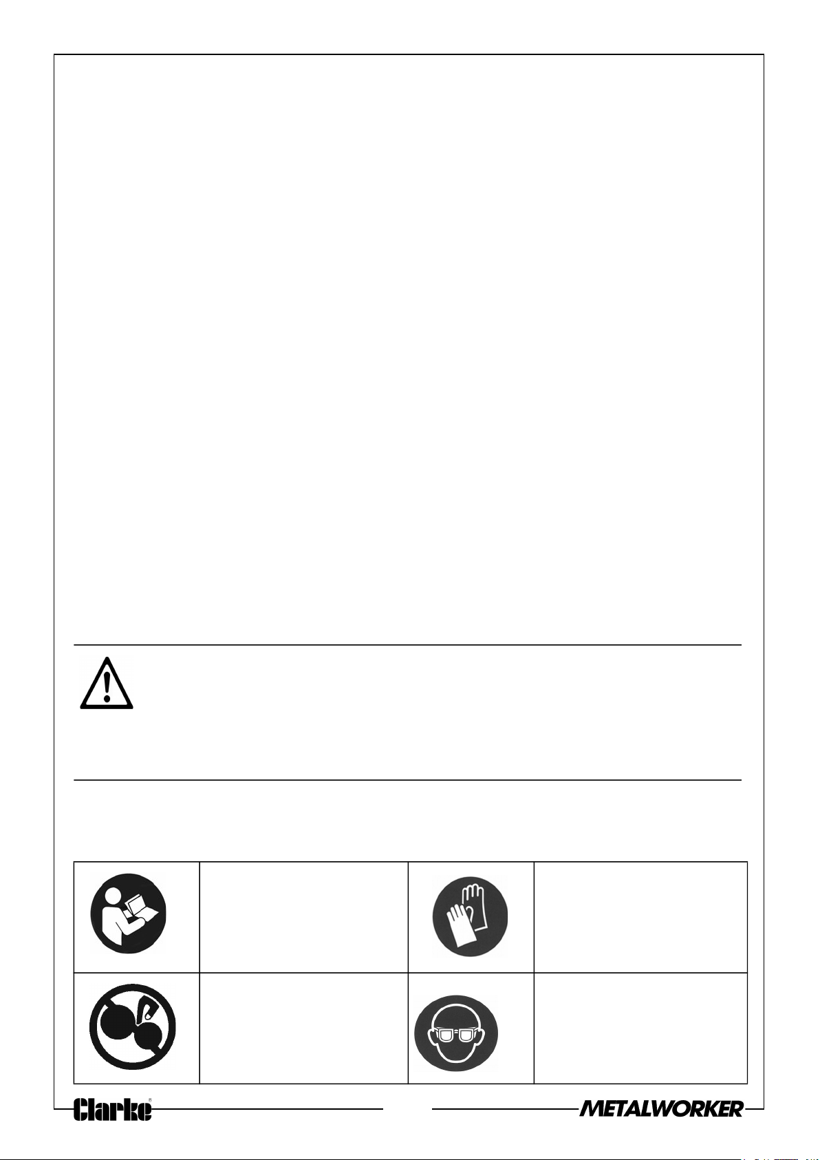
SAFETY SYMBOLS ON THE MACHINE
The following symbols appear on the machine
Read this manual
before use.
Wear hand protection
when using the
machine.
Keep fingers clear of
break, dies, rollers and
blade.
Wear eye protection
4
Page 5
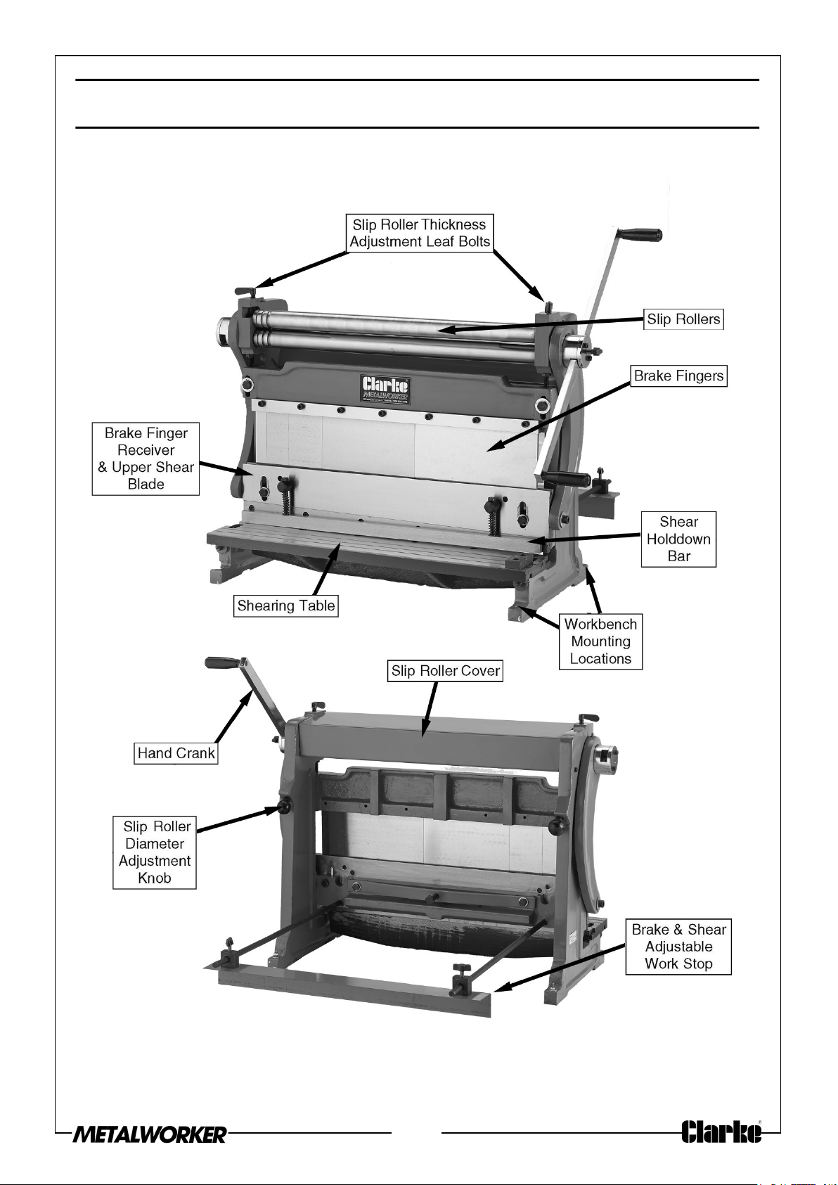
PARTS IDENTIFICATION
Fig. 1
5
Page 6
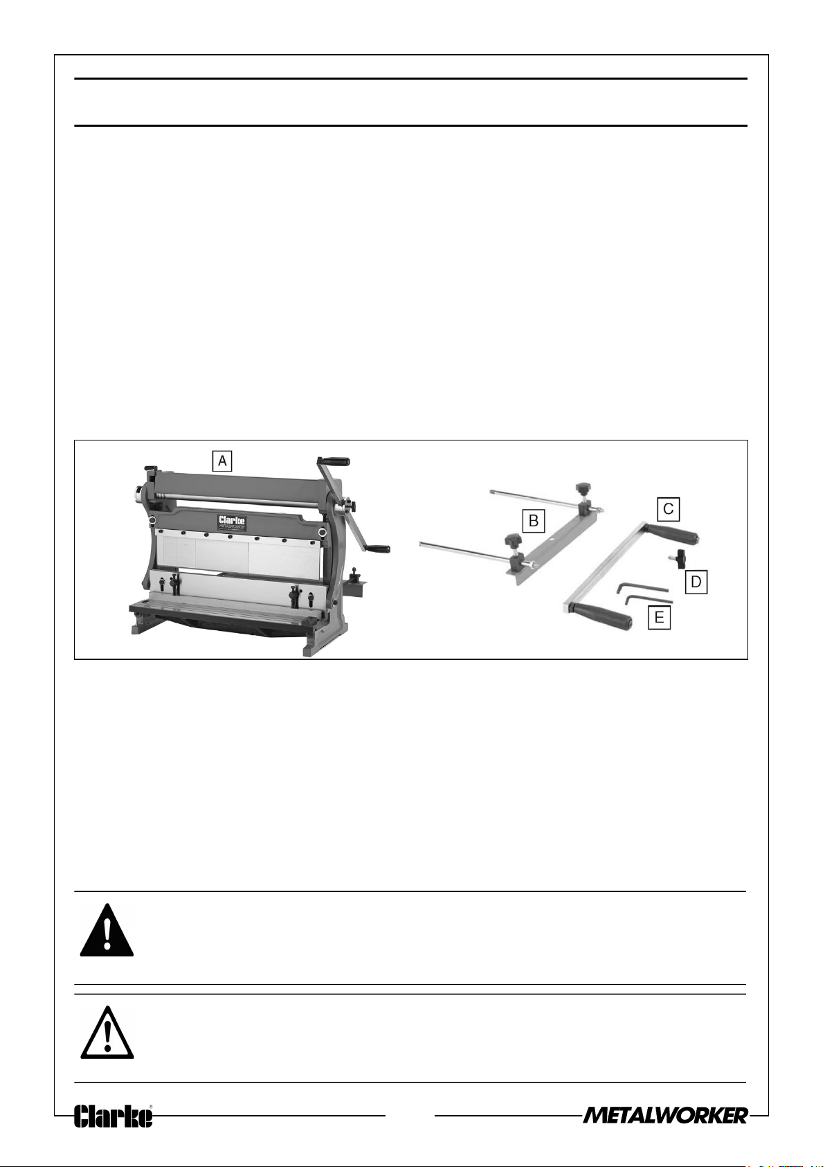
UNPACKING AND SETUP
Remove the packaging materials from around your machine and make sure that you
have the following items. If you discover the machine is damaged in any way, please
contact your CLARKE dealer.
Remove the packaging materials from around your machine and make sure that you
have the following items. If you discover the machine is damaged in any way, please
contact your CLARKE dealer.
• A. Sheet Metal Machine
• B. Shear & Brake Rear Work Stop
• C. Hand Crank Handle
• D. Hand Crank Lock Knobs
• E. Hex Wrenches
Fig. 2
Fig. 3
CLEAN UP
The unpainted surfaces are coated with a waxy oil to prevent corrosion during
shipment. Remove this protective coating with a solvent cleaner or degreaser. For
thorough cleaning, some parts must be removed.
For optimum performance, clean all moving parts or sliding contact surfaces. Avoid
chlorine-based solvents, such as acetone or brake parts cleaner that may damage
painted surfaces.
Always follow the manufacturer's instructions when using cleaning products.
WARNING: PETROL AND PETROLEUM BASED PRODUCTS HAVE LOW
FLASHPOINTS AND CAN EXPLODE OR CAUSE FIRE IF USED TO
CLEAN MACHINERY. DO NOT USE THESE PRODUCTS TO CLEAN THE
MACHINERY.
CAUTION: MANY CLEANING SOLVENTS ARE TOXIC IF INHALED. MINIMIZE
YOUR RISK BY ONLY USING THESE PRODUCTS IN A WELL VENTILATED
AREA.
6
Page 7
SITE CONSIDERATIONS
FLOOR LOAD
Refer to the Specifications for the weight and footprint specifications of your machine.
Some workbenches or stands may require additional reinforcement to support the
machine, workpiece, and the forces applied during operation.
PLACEMENT LOCATION
Consider existing and anticipated needs,
size of material to be processed through
each machine and space for auxiliary
stands, work tables or other machinery
when establishing a location for your
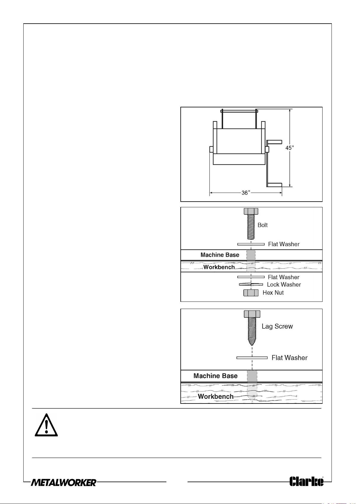
new machine. See Figure 4 for the
minimum working clearances.
MOUNTING
The base of this machine has holes that
allow it to be mounted to a workbench.
For a safe and smooth operation of this
machine, it MUST be securely mounted
to an appropriate workbench or stand.
The strongest mounting option is a
“Through Mount” (Figure 5) where holes
are drilled all the way through the
workbench, and hex bolts, washers and
hex nuts are used to secure the machine
to the workbench.
Fig. 4
Fig. 5
Another option for mounting is a “Direct
Mount” (Figure 6) where the machine is
simply secured to the workbench with a
lag screw.
CAUTION: DUE TO THE CONSIDERABLE FORCES EXERTED ON THIS
MACHINE WHEN IN OPERATION, YOU MUST SECURELY MOUNT IT TO A
STABLE AND STURDY WORKBENCH OR STAND. OTHERWISE, THE MACHINE
COULD TIP OR FALL AND RESULT IN PERSONAL INJURY OR PROPERTY
DAMAGE.
Fig. 6
7
Page 8
ASSEMBLY
In addition to the assembly procedures below, some disassembly is required to
remove storage grease and re-lubricate the cleaned parts.
ASSEMBLING THE MACHINE
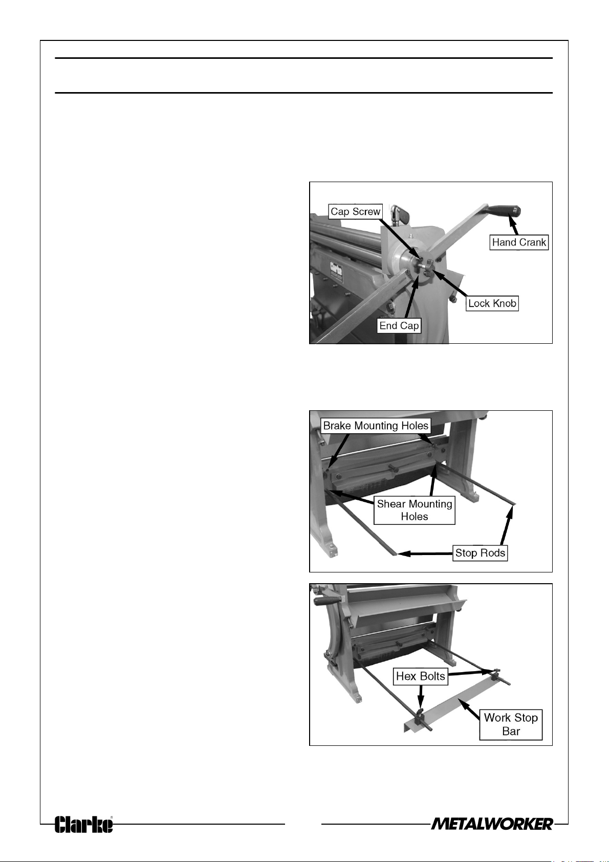
1. Remove one of the end cap screws
from the end cap, loosen the other
cap screw and rotate the end cap out
of the way.
2. Rotate the lock knob out until it is
flush with the rear of the end cap.
3. Insert the hand crank into the slot
(see Figure 7).
4. Replace the end cap and cap screws
and tighten the lock knob.
NOTE: It is your preference which side of the machine you install the hand
crank.
Fig. 7
5. Thread the rods into either the brake
or sheer mounting holes, as shown in
Figure 8. Only hand-tighten the rods.
6. Loosen the hex bolts on the stop bar
and slide it onto the rods.
7. Position the stop bar as required and
secure using the hex bolts as shown
in Figure 9.
Fig. 8
Fig. 9
8
Page 9
OPERATING - SLIP ROLLERS
CAUTION: THE ROLLERS OF THIS MACHINE PRESENT A PINCHING HAZARD.
MAKE SURE NO BODY PART OR CLOTHING IS NEAR THE ROLLERS DURING
OPERATION. FAILURE TO FOLLOW THIS WARNING MAY RESULT IN
FINGERS, HAIR, OR CLOTHING BEING PULLED INTO THE MACHINE,
CAUSING PERSONAL INJURY.
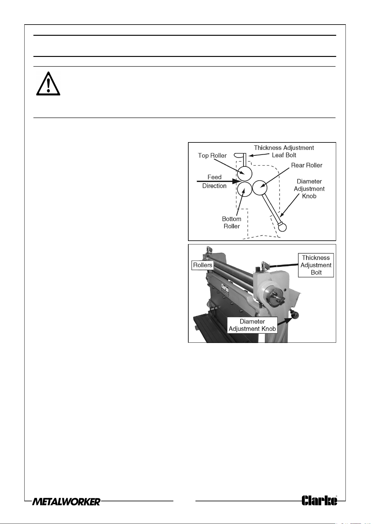
SLIP ROLLER OVERVIEW
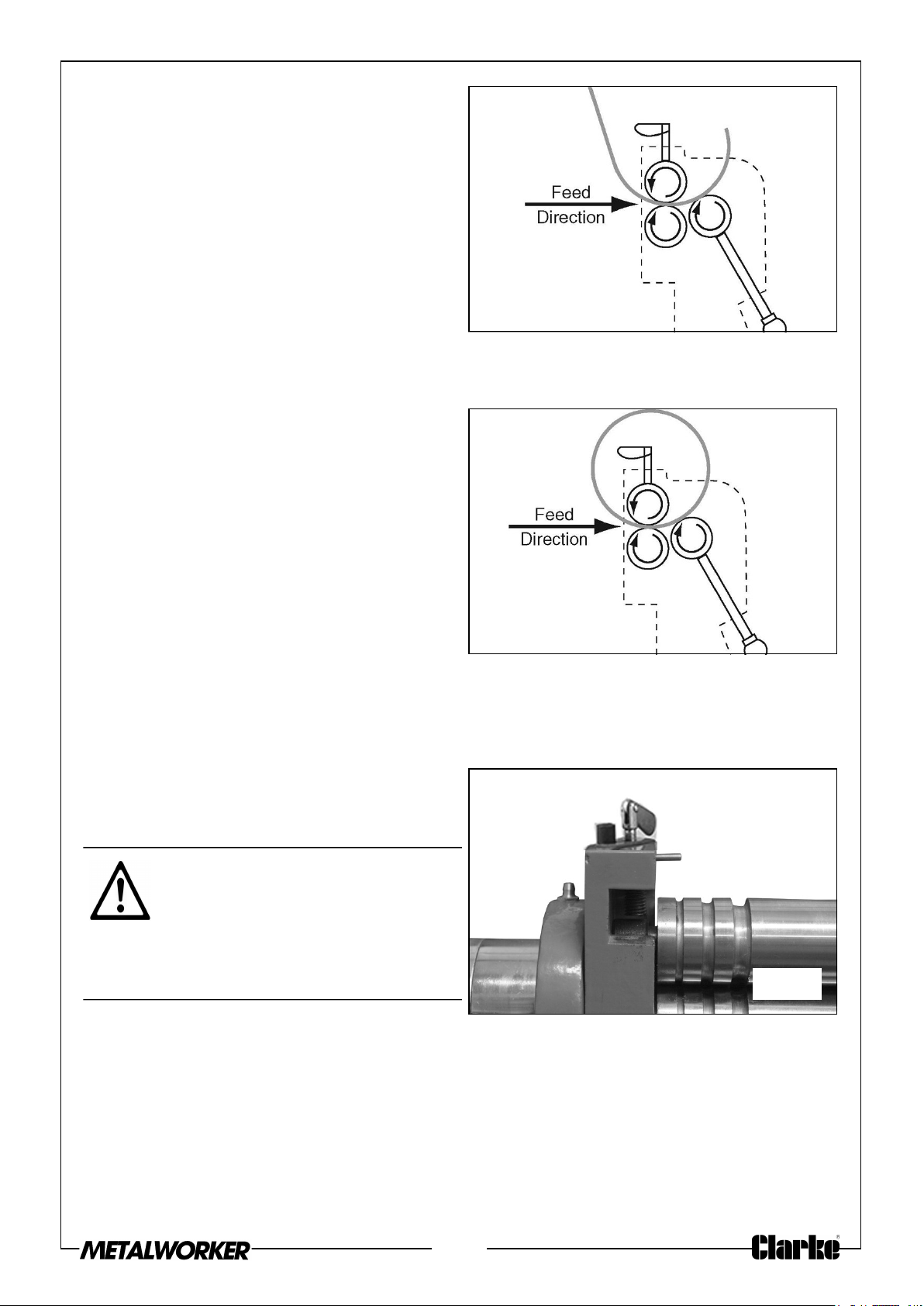
The slip roller is used to form cylinders,
cones, and arcs in sheet metal up to 1
mm in thickness and 760 mm wide, as
well as wires and rods. Three steel rollers
are configured to draw the workpiece
through a path that will produce the
desired results (see Figures 10-11).
SLIP ROLLING TIPS
• Due to the many variables of different sheet metal types, no single
configuration of the rollers will create the same curve on all materials. Rolling
sheet metal to achieve an exact radius is a trial-and-error process.
• Performing multiple passes through the machine with gradual reductions in the
curve radius produces better results than trying to make the curve in one pass.
• To avoid pitted workpieces and damage to the roller surfaces, always make
sure the workpiece and the rollers are free of grit and any foreign material
before every use.
Fig. 10
Fig. 11
• Unless the operation requires a cone-type curve, always keep the rear
roller parallel to the front rollers by rotating the diameter adjustment knobs
the same amount.
9
Page 10
CREATING CURVES
Your sheet metal machine can easily create constant radius curves in sheet metal up
to 1 mm in thickness (mild steel).
The method of creating a specific radius is a trial and error process. Due to the many
variations among metal workpieces, no single configuration of the rollers will
reproduce the same curve in all materials. We recommend testing your roller
configurations on scrap pieces that are the same dimension and material as your final
workpiece.
TO CREATE A CURVE IN THE WORKPIECE:
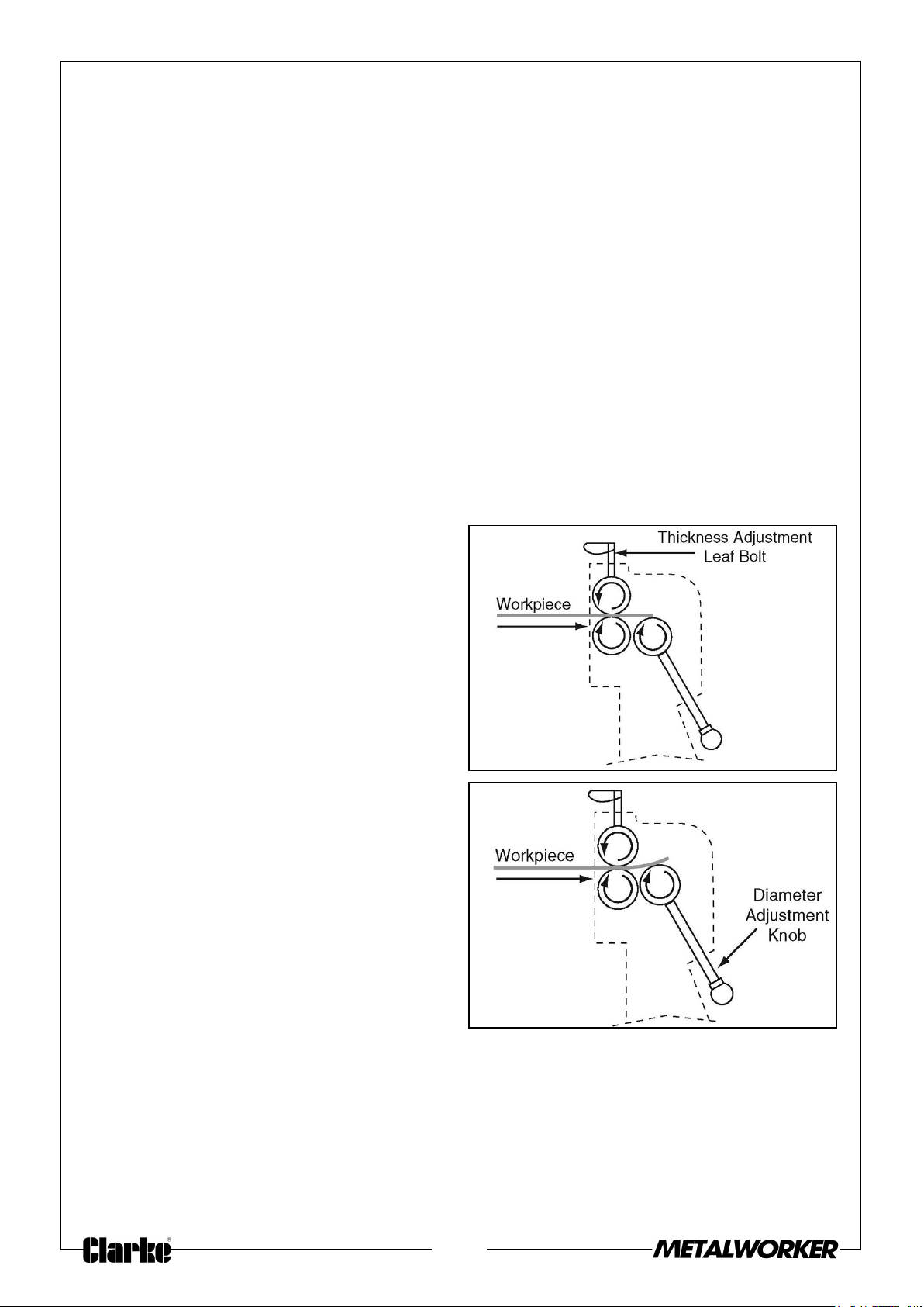
1. Use the diameter adjustment knobs to fully lower the rear roller below the level of
the bottom roller, then rotate the thickness adjustment leaf bolts counterclockwise
until the upper roller can be lifted with enough clearance for the workpiece.
NOTE: Performing multiple passes through the machine with gradual reductions in
the curve radius produces better results than trying to make the curve in
one or two passes.
2. Insert the workpiece between the
upper and lower rollers and just over
the rear roller, as illustrated in Figure
12, then tighten the thickness
adjustment leaf bolts down to hold
the workpiece securely. Make sure
you tighten the leaf bolts exactly the
same amount.
3. Use the diameter adjustment knobs
to raise the rear roller, then use the
hand crank to pass the workpiece
through the machine (see the
illustrations in Figure 13-14).
NOTE: For good results, make the first
bend about 25% of the final
radius, then slightly increase
the bend by 25% with each
successive pass until the final
radius has been reached.
Fig. 12
Fig. 13
10
Page 11
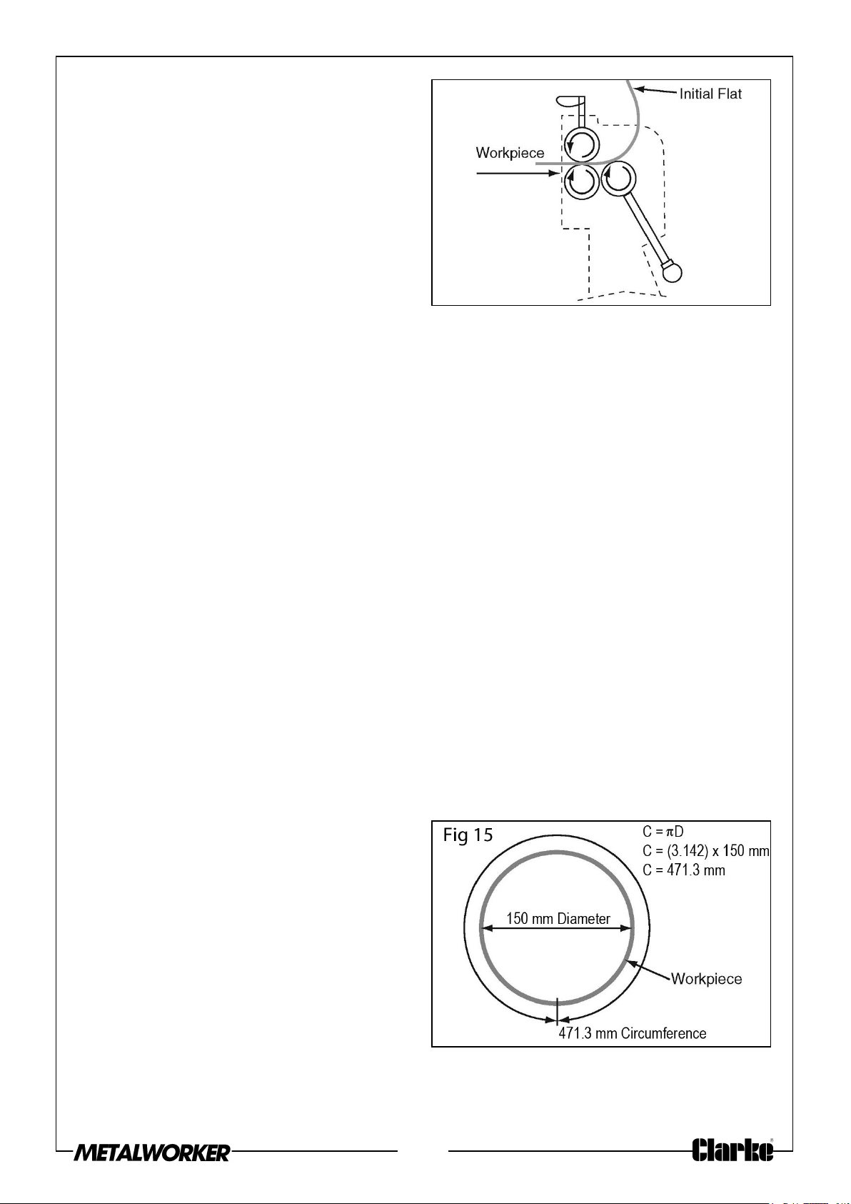
NOTE: If your workpiece has an
undesired initial flat, as
illustrated in Figure 14, you can
remove it by flipping the
workpiece around and pass it
through the front of the
machine so that the initial flat
enters last.
4. Slightly tighten the diameter
adjustment knobs the same amount,
then pass the workpiece through the
rollers again.
NOTE: To make a cone, tighten one adjustment knob more than the other.
5. Repeat Step 4 until you have produced the desired curve.
Fig. 14
CREATING CYLINDERS
If you know the diameter of the cylinder you want to create, use the formula below to
calculate the length of material needed.
C=πD
C = Circumference (Length of Material Needed)
π = Pi (Approximately 3.142)
D = Diameter
Example: Suppose you want to create a 150 mm diameter cylinder. You would use the
above formula as follows:
C = πD
C = (3.142) x 150 mm
C = 471.3 mm
The result of 471.3 mm indicates that
you need to start with a piece of sheet
metal that is approximately 471.3 mm in
length in order to create a 150 mm
diameter cylinder.
You can use the slip roll to create a bend
with the correct radius so that the two
ends meet, forming a 150 mm diameter
cylinder (Figure 15).
NOTE: Performing multiple passes
through the machine with gradual reductions in the curve radius produces
better results than trying to make the curve in one or two passes.
Fig. 16
11
Page 12
TO CREATE A CYLINDER:
1. Use the diameter adjustment knobs to fully lower the rear roller below the level of
the bottom roller, then rotate the thickness adjustment leaf bolts counterclockwise
until the upper roller can be lifted with enough clearance for the workpiece.
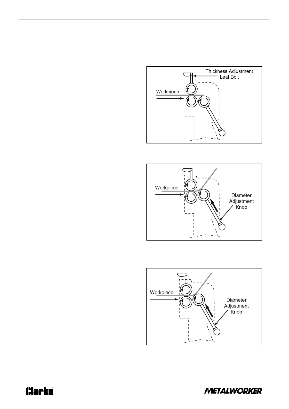
2. Insert the workpiece between the
upper and lower rollers and just over
the rear roller, as illustrated in Figure
16, then snug the thickness
adjustment leaf bolts down to secure
the workpiece. Make sure you tighten
the leaf bolts the same amount.
3. Turn the hand crank clockwise to
feed the workpiece through the
machine until it is approximately half
way through the upper and lower
rollers.
4. Turn the diameter adjustment knobs
clockwise knobs to lift the rear roller
until the desired radius bend is
reached, as illustrated in Figure 17.
Make sure to turn the knobs equal
amounts so the rear roller is always
parallel with the other rollers. Failure
to do so will create a larger radius on
one end than the other, resulting in a
cone shape.
Fig. 16
Fig. 17
NOTE: Always err on the side of
making the radius too large rather than too small. It is easy to decrease the
radius but very difficult to increase the radius later.
5. Turn the hand crank to process the
material through the slip rollers.
Continue turning until the workpiece
is completely through the upper and
lower rollers, as illustrated in Figure
18.
Fig. 18
12
Page 13
6. Rotate the workpiece 180°, insert the
curved end into the rollers, then
process it through the machine, as
illustrated in Figure 19.
7. Reduce the radius of the curve by
raising the rear roller, then repeat
Steps 4-7 until you have produced
the desired cylinder (see the
illustration in Figure 20).
• If the ends of the cylinder do not
meet, lift the rear roller equally at both ends, then process the entire cylinder
through the slip roller again. Repeat as necessary.
• If the ends of the cylinder overlap,
remove the cylinder as described
in “Removing the Workpiece from
the Rollers”. Then, either attempt
to increase the radius by manually
bending it, or scrap the workpiece
and start this procedure again
with a new blank.
Fig. 19
Fig. 20
8. When the cylinder is complete, refer
to Removing the Workpiece from the
Rollers” for detailed instructions on
removing the cylinder from the top roller.
REMOVING THE WORKPIECE FROM THE ROLLERS
1. Rotate the thickness leaf bolts
anticlockwise until they no longer
apply pressure to the top roller.
CAUTION: THE SHARP EDGES OF
SHEET METAL CAN QUICKLY CUT
YOUR HANDS. ALWAYS USE
CAUTION AND HEAVY LEATHER
GLOVES WHEN HANDLING SHEET
METAL.
Fig. 21
13
Page 14
2. Protect your hands from the sharp
edges of the workpiece, then grasp
the top roller and use moderate force
to pull it forward, as shown in Figure
22.
3. Remove the workpiece, slide the top
roller back into place, then secure the
roller by rotate the thickness leaf
bolts clockwise to apply the required
pressure to the top roller.
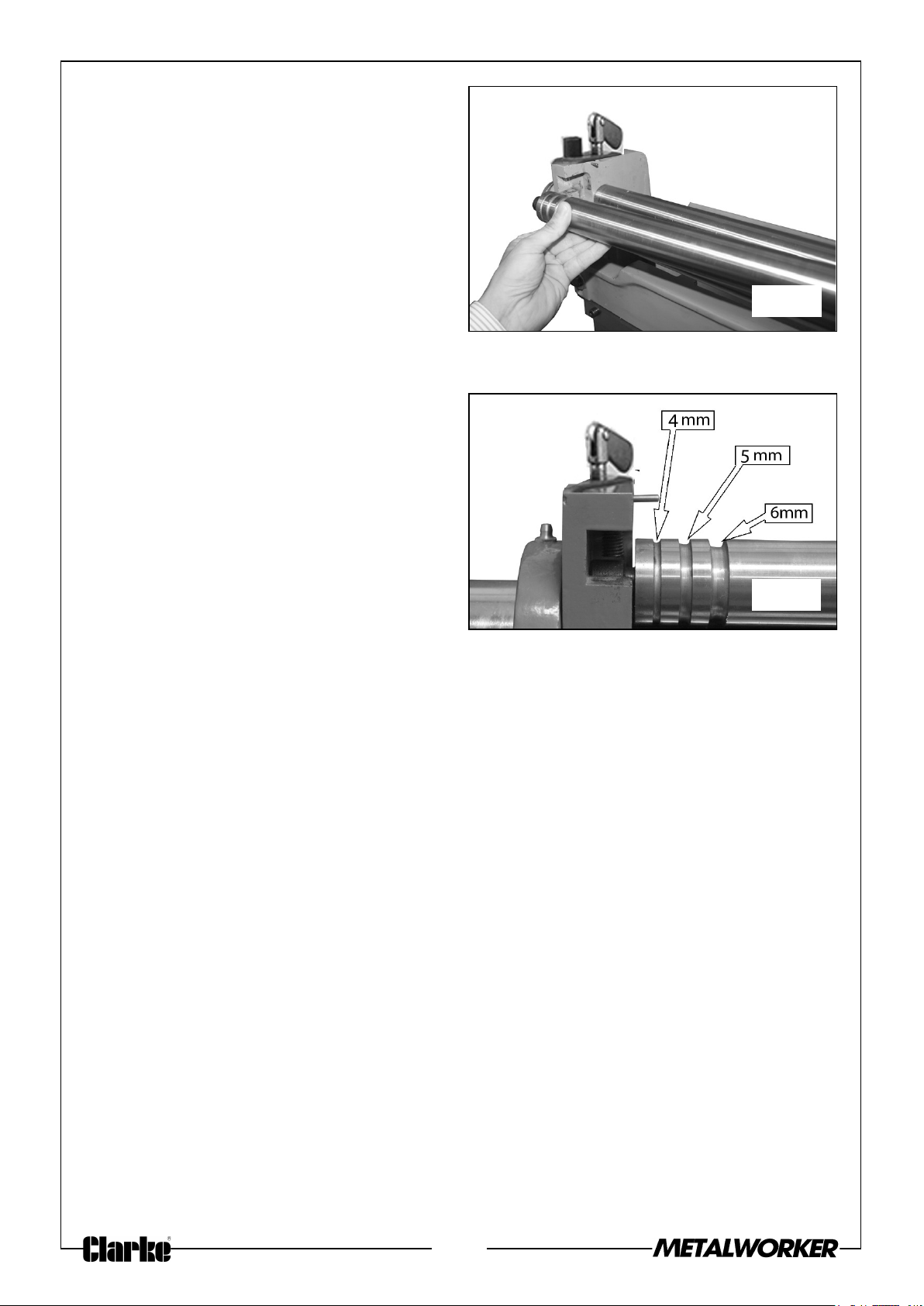
BENDING WIRE
Your sheet metal machine can bend
wires, rods, and small-diameter tubing
with diameters of 3.97 mm, 4.37 mm
and 5.56 mm (see Figure 23).
To ensure even pressure on the material,
place the workpiece in the smallest
possible groove on the rollers.
Fig. 22
Process the material through the
machine in the same manner described
on the previous pages for sheet metal.
NOTE: The wire grooves can also be used when rolling sheet metal that has a wire
bead on the side.
Fig. 23
14
Page 15
OPERATING - BRAKE
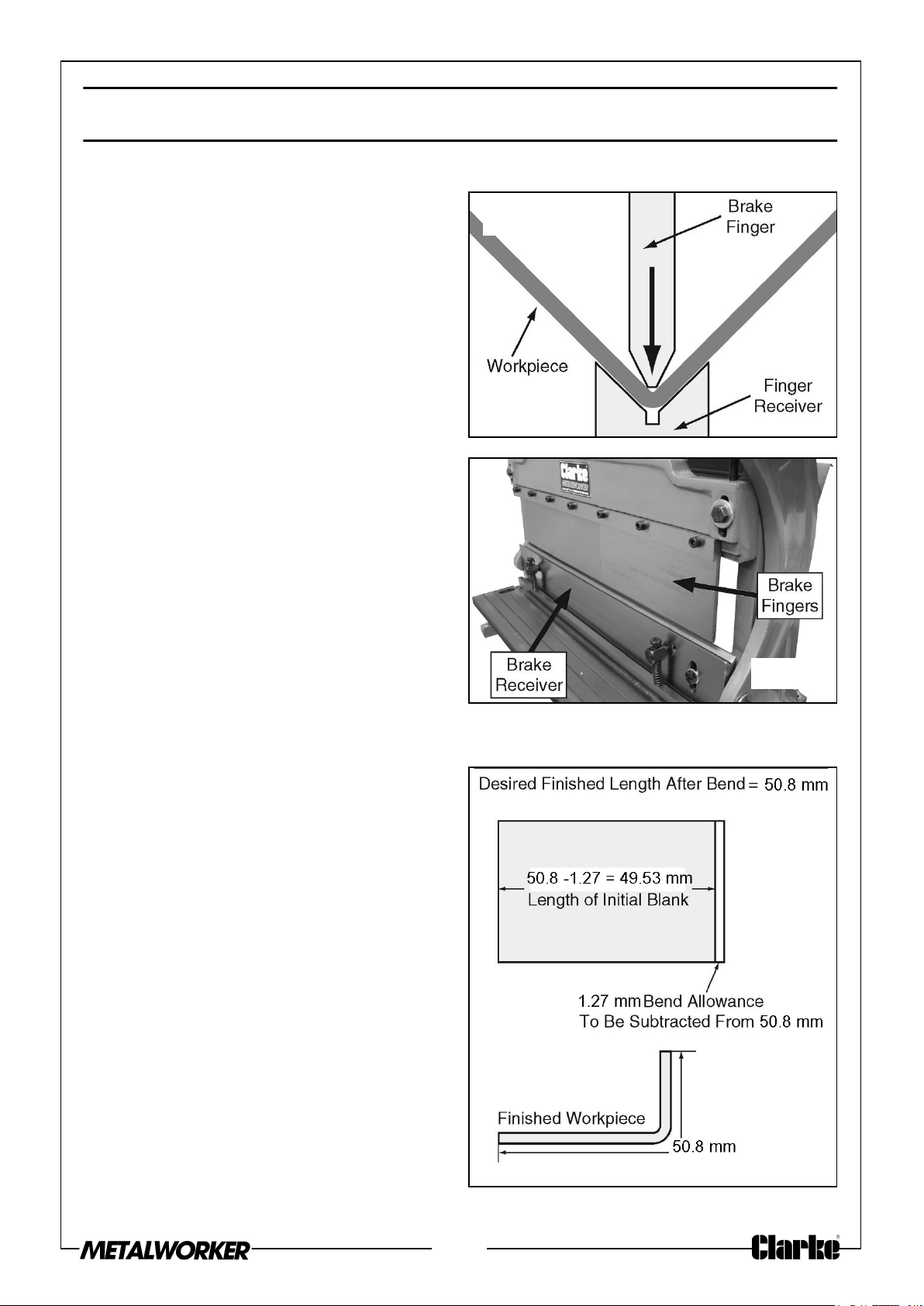
BRAKE OVERVIEW
The brake of the SBR610B is used to
make bends of 0°-90° in sheet metal up
to 1 mm in thickness and 610 mm in
width. When you use the hand crank, the
brake fingers force the workpiece into
the groove of the finger receiver to make
the desired bend (see Figures 24-25).
BENDING ALLOWANCE
When metal is bent, the outside overall
dimension increases from its original
length-this amount is called the bend
allowance. A typical bend allowance for a
90° bend in a 1 mm mild steel workpiece
is approximately 1.27 mm. That means
you need to start with a workpiece that
is approximately 1.27 mm shorter than
the desired outside length of the finished
workpiece, as illustrated in the example
of Figure 26.
Fig. 24
Fig. 25
Calculating the bend allowance for your
operation requires many variables, such
as metal thickness, type of material,
radius of the bend, etc. Detailed
information for calculating the bend
allowance can be found in metalworking
handbooks and on the internet.
An easy way to find the correct
dimension of your initial blank is to
measure a piece of scrap of the same
material as the workpiece, make the
bend, then measure the piece again. The
difference between the two
measurements is the bend allowance,
which you subtract from the dimension
of the workpiece blank before the bend.
Fig. 26
15
Page 16
BENDING SHEET METAL
Tip: To reduce the chance of scoring your workpiece when using the brake, always
keep the fingers and receivers clean and lubricated (refer to pages 20-21 for detailed
instructions), and free of burrs or other blemishes. Also, apply a strip of sturdy tape
along the top and bottom of the bend line.
WARNING: THE BRAKE FINGERS ON THIS MACHINE PRESENTS A
PINCHING HAZARD. MAKE SURE NO BODY PART OR CLOTHING IS
NEAR THE AREA WHERE METAL BENDING OCCURS. FAILURE TO
FOLLOW THIS WARNING MAY RESULT IN SEVERE PERSONAL
INJURY.
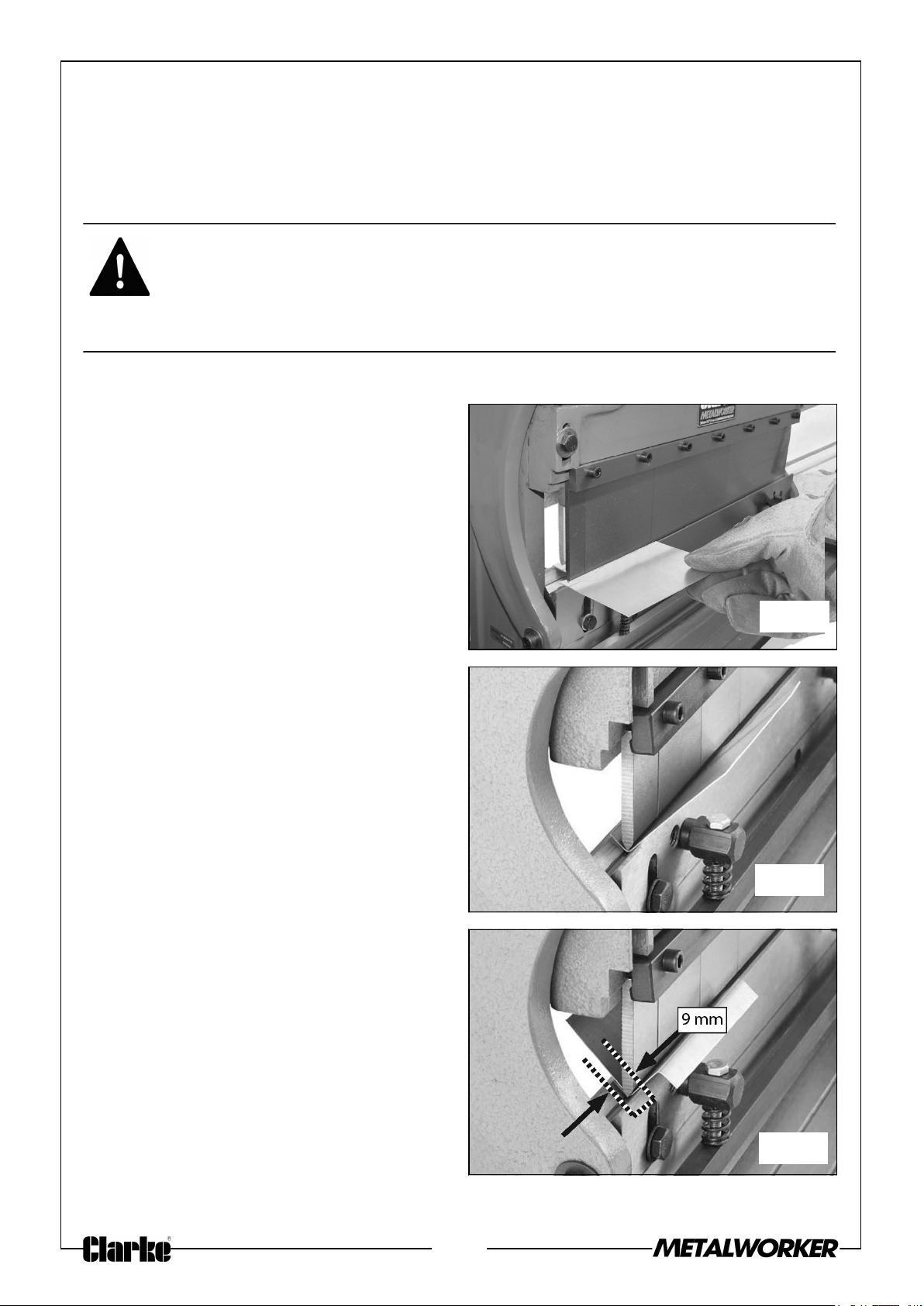
1. Mark a line along the width of the workpiece where the bend is to take place.
2. Use the hand crank to lower the
finger receiver until you can position
the workpiece underneath the fingers
with the bend line aligned with the
tips, as shown in Figure 27.
NOTE: When performing the same
bending operation on multiple
parts, use the rear work stop to
save time positioning the
workpieces.
Fig. 27
3. While holding the workpiece steady,
use the hand crank to raise the finger
receiver to perform the desired bend
(see Figure 28 for an example), then
lower the receiver and remove the
workpiece.
4. If a reverse bend is required, reinstall the workpiece upside-down, as
shown in Figure 29, and repeat Steps
2-3. The minimum reverse bend
possible is 9 mm.
When performing a pan and box bending
operation, loosen the cap screws on the
brake finger gib and configure the
fingers for your operation. Remove the
fingers you do not need.
Fig. 28
Fig. 29
16
Page 17
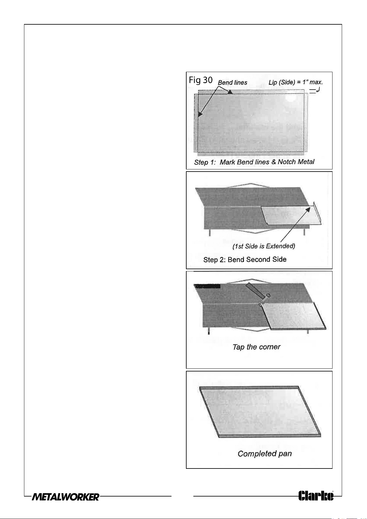
PAN FORMING
The hand brake roller can be used to make various sizes of pans. The maximum lip
(side) height supported by this tool is 1”.
To form a pan;
1. Pre-measure and cut your material
before bending. Notch the corners
according to the desired lip height as
shown in Fig 30.
2. Insert material between the fingers
and the moving cutter plate. Bend
the material until a 90 degree angle
has been formed.
3. Rotate the material 90 degrees
counter-clockwise. Allow the
completed side to extend just beyond
the dies. Bend the second side.
Fig. 34
4. Repeat step 3 for the 3rd side.
5. Rotate to the final side and insert the
workpiece between your dies. Your
formed sides will be on the outside of
the dies.
6. Before bending, tap one corner
nearer to the middle of the machine.
This will allow the material to clear
the fingers when raised.
7. Bend the fourth side.
8. Using a block or piece of wood, tap
the corner of the material back into
place.
Fig. 34
Fig. 34
17
Fig. 34
Page 18
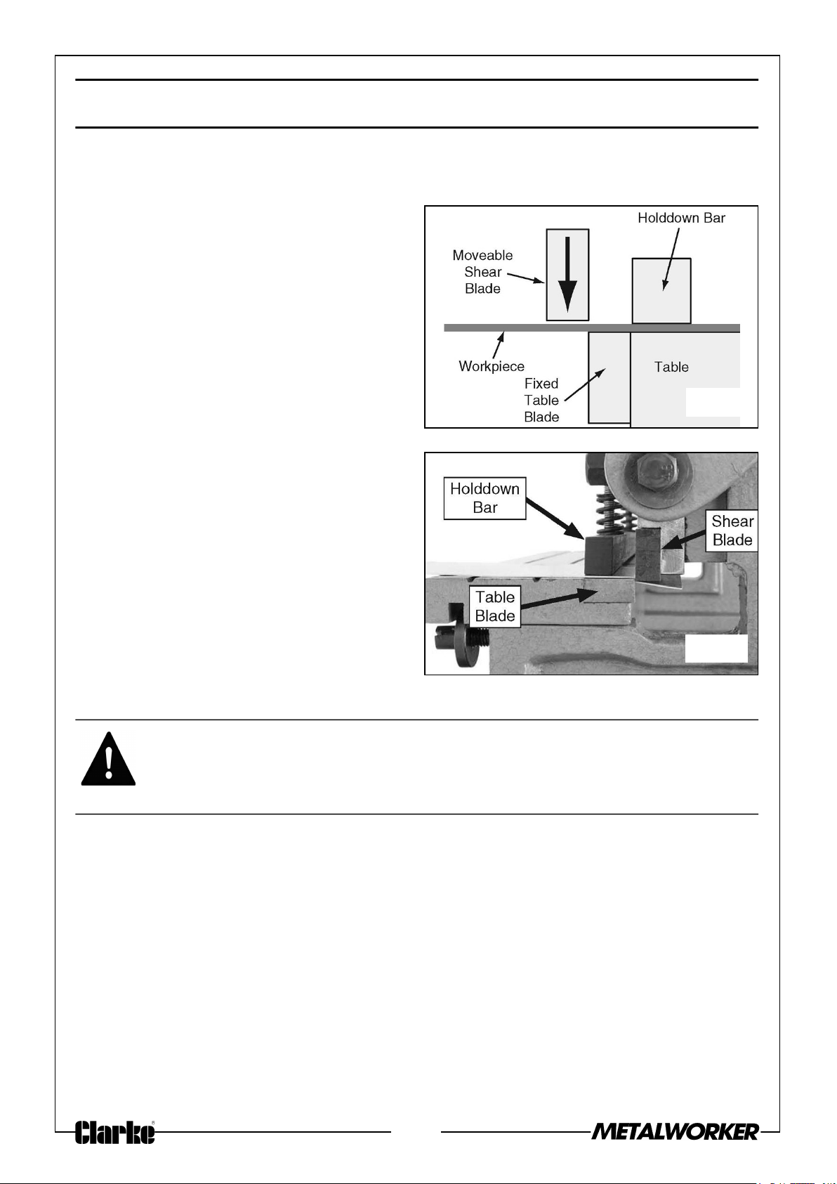
OPERATING - SHEARING
SHEARING OVERVIEW
The SBR710B has a set of reversible
blades that shear mild steel up to 1 mm
in thickness and 760 mm in width. When
you use the hand crank to perform a
shear, the upper movable blade is
lowered past the fixed table blade,
creating a shearing action (see Figures
34-35). For repetitive cuts, use the
adjustable rear work stop.
Fig. 34
Fig. 35
CUTTING SHEET METAL
WARNING: THE SHEARING BLADES ON THIS MACHINE PRESENT A
HAZARD. MAKE SURE NO BODY PART OR CLOTHING IS NEAR THE
AREA WHERE METAL SHEARING OCCURS. FAILURE TO FOLLOW
THIS WARNING MAY RESULT IN SEVERE PERSONAL INJURY.
1. Mark the cut line across the width of the workpiece.
2. Make sure the gap between the shearing blades is correct for the workpiece
material (refer to “Shearing Blade Gap Adjustment” on page 24 for detailed
instructions).
18
Page 19
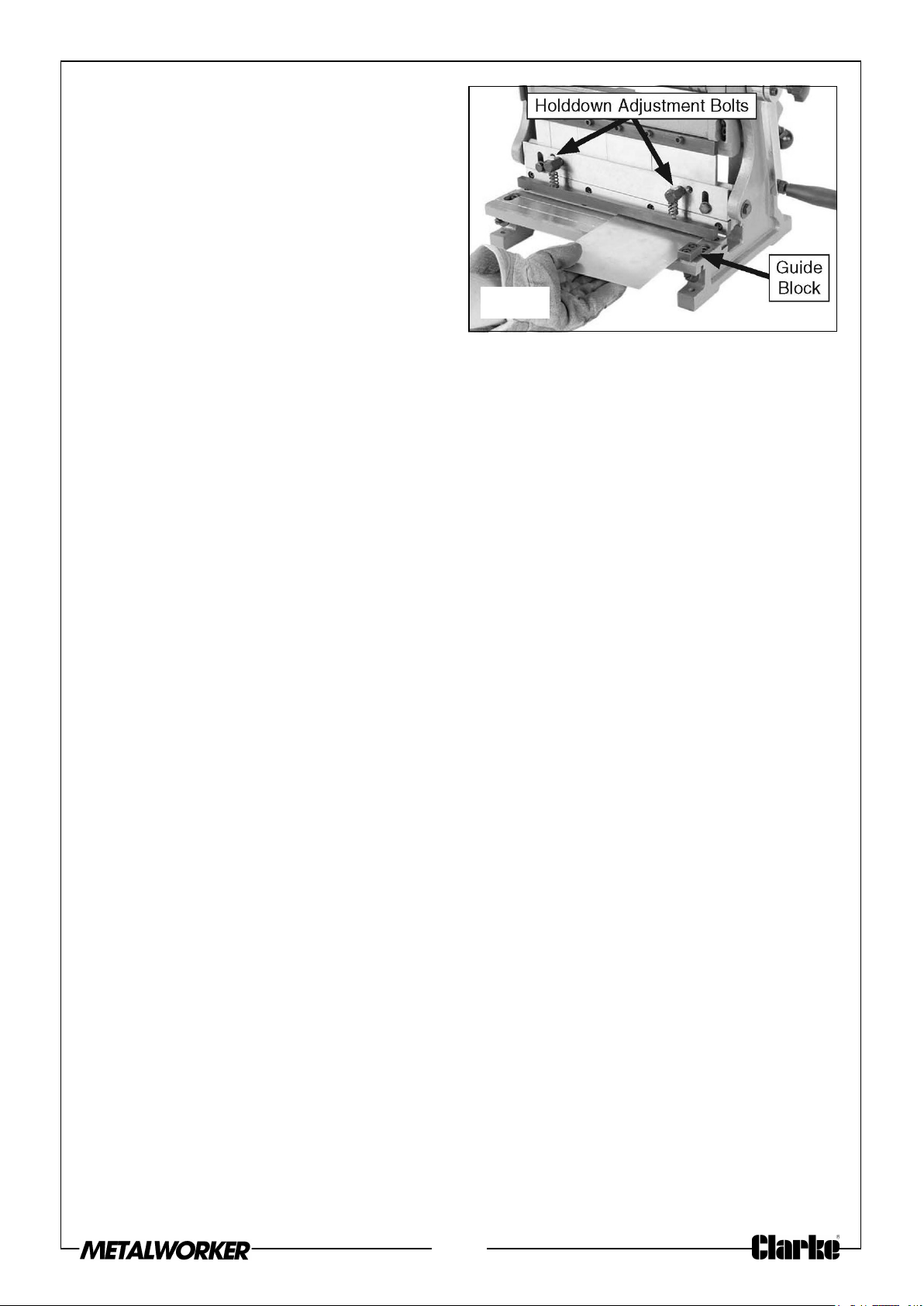
3. Position the workpiece up against the
guide block on the right side of the
table, then align the cut mark with
the upper shear blade, as shown in
Figure 36.
NOTE: The shearing action begins on
the right side of the workpiece
and moves to the left.
NOTE: If you need to adjust the gap
Fig. 36
between the shearing blades to
accommodate your workpiece, refer to the “Shearing Blade Gap
Adjustment” on page 24 for detailed instructions.
NOTE: If you are using the rear work stop, adjust the stop so that at least one
square edge of the workpiece is against it.
4. Use the hold down adjustment bolts to adjust the hold-down bar so that it firmly
holds the workpiece in place without marking or denting it.
5. Keeping all body parts away from the blades, rotate the hand crank with an even
and steady pressure to complete the cut.
19
Page 20
MAINTENANCE
SCHEDULE
For optimum performance from your machine, follow this maintenance schedule and
refer to any specific instructions given in this section.
DAILY MAINTENANCE
• Clean the machine.
• Tighten loose mounting bolts.
• Check/replace damaged rollers.
• Check/replace cracked or damaged brake fingers or receiver.
• Sharpen/replace dull or nicked shearing blades.
• Any other unsafe condition.
MONTHLY MAINTENANCE
• Lubricate the gears and hand crank bushings.
6 MONTHLY MAINTENANCE
• Lubricate the roller bushings.
CLEANING
Cleaning the SBR760B is relatively easy. Use cloth and de-greasing spirits to wipe
down the machine.
LUBRICATION
Keep your machine properly lubricated to help ensure long life and smooth operation
of the machine.
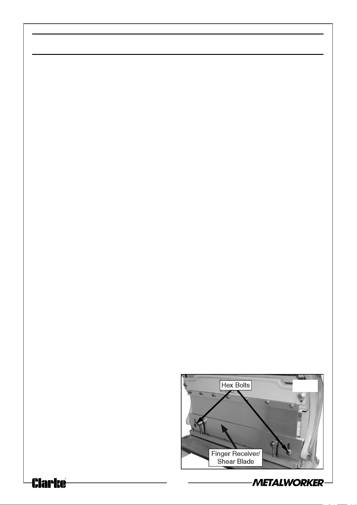
CLEANING THE MACHINE FINGERS
1. Loosen the two hex bolts securing
the finger receiver/upper shear blade
to the frame (see Figure 37).
Fig. 37
20
Page 21
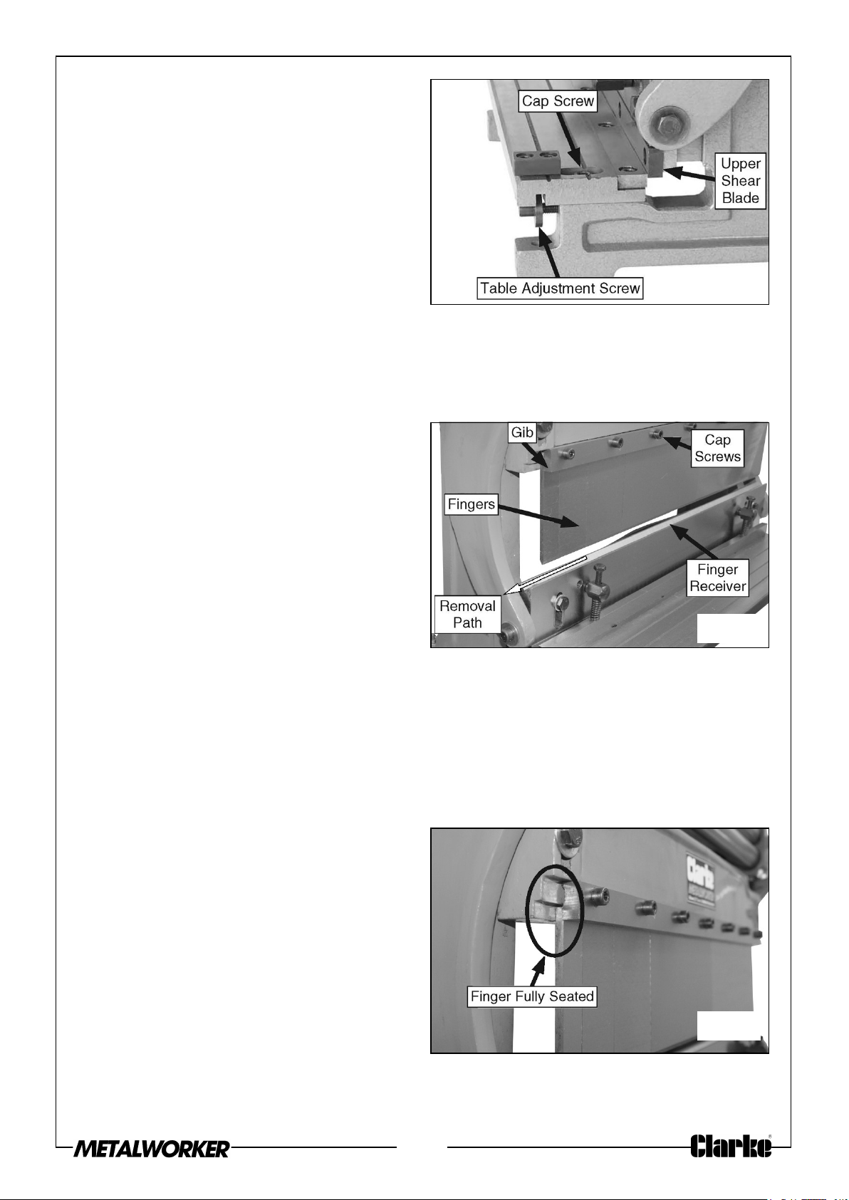
2. Move the table back until the upper
shear blade can pass down behind
the table blade by loosening the two
cap screws securing the shear table
to the frame and rotating the table
adjustment screws counterclockwise
(see Figure 38).
NOTE: Operational adjustment of the
shearing blades is covered in
the “Shearing Blade Gap
Adjustment” on page 24.
3. Make sure the finger receiver and upper shear blade move up and down smoothly,
re-tighten the hex bolts just until they are snug, then back them off approximately
¼ turn.
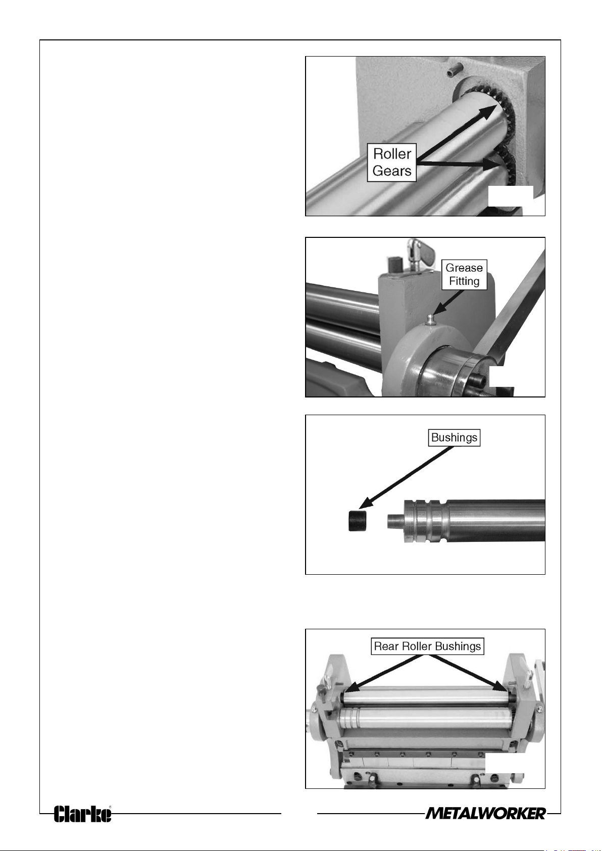
4. Use the hand crank to position the
brake finger receiver close to the
brake fingers, as shown in Figure 39.
Fig. 38
5. Loosen the gib cap screws to release
the fingers, then remove the fingers
from the side of the finger receiver,
as shown in Figure 39.
6. Use cloth and a de-greaser to remove
the storage grease from the fingers,
gib, and receiver. Thoroughly dry the
parts, then apply a thin coat of an anti-rust lubricant to all the parts.
7. Place a thin piece of wood on the finger receiver, as shown in Figure 39, then
reinstall the fingers so that they rest on the wood. Make sure the tops of the
fingers are between the gib and the casting.
NOTE: Install the widest finger to the right, then repeat with each smaller
finger.
8. Make sure the fingers are slightly
loose between the gib and the
casting, then use the hand crank to
raise the receiver to fully seat the
fingers up against the casting behind
the gib, as shown in Figure 40.
Fig. 39
9. Re-tighten all of the gib cap screws.
Fig. 40
21
Page 22
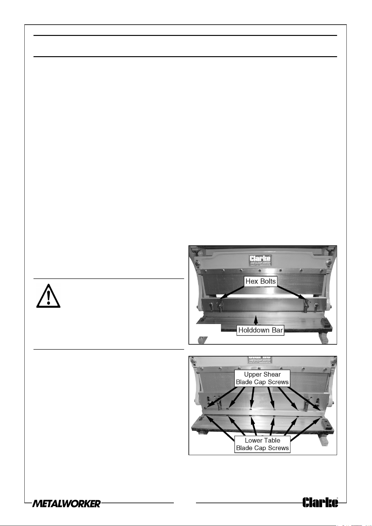
GEARS
Clean away grease and built-up grime
from the top and bottom roller gear
teeth, as shown in Figure 41, with a stiff
brush and de-greasing spirits.
When dry, apply a small amount of
grease to the teeth, then use the hand
crank to rotate the rollers and distribute
the lubricant.
HAND CRANK BUSHINGS
Wipe off the grease fittings next to each
hand crank hub (see Figure 42), then use
a grease gun to add a small amount of
multi-purpose grease to the hand crank
bushings.
Fig. 41
ROLLER BUSHINGS
1. Remove the top roller from the
machine, then remove the bushings
from the ends of the roller (see
Figure 43).
2. Use a shop rag and de-greasing
spirits to clean the bushings and the
ends of the roller.
3. Apply a thin coat of multi-purpose
grease to the roller ends.
4. Re-install the bushings.
5. Use a stiff brush and de-greasing
spirits to clean the rear roller
bushings (see Figure 44).
Fig. 42
Fig. 43
6. Apply a small amount of multipurpose grease to them.
7. Re-install the top roller and close the
cover.
Fig. 44
22
Page 23
SERVICING
SHEARING BLADE REVERSAL/REPLACEMENT
The shearing blades are reversible, so when the first cutting edge becomes dull, the
blades can be rotated to use the second cutting edge.
When both cutting edges of the blade become dull, use wet grinding techniques for
SK-4 metal or better to sharpen the cutting face of the blade.
The upper shearing blade uses a 5° relief edge and the lower table blade does not.
However, if you are not comfortable performing the sharpening procedure or do not
have access to a professional sharpening service, replacement blades are available
through the Clarke spares department.
Tools Needed
• Wrench or socket 10mm
• Hex wrench 5mm
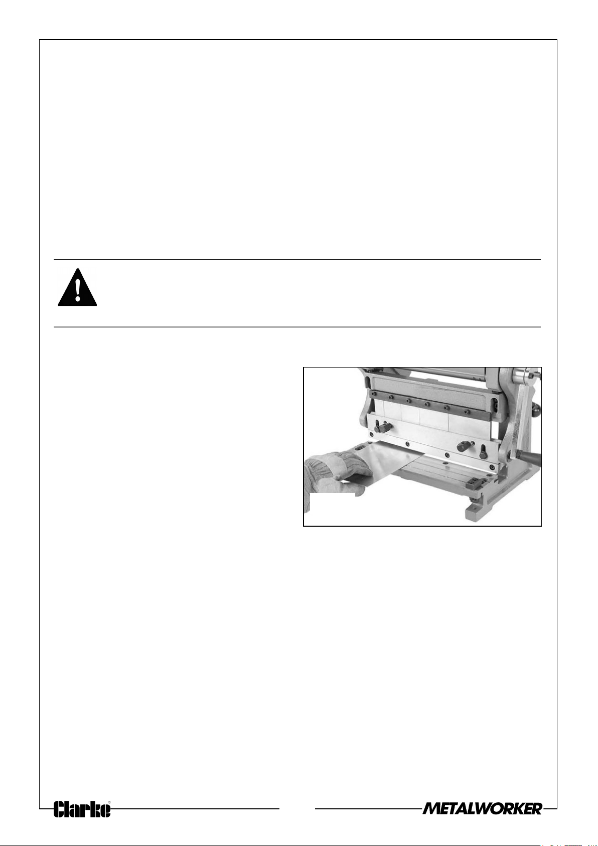
TO REVERSE OR REPLACE THE SHEARING BLADES:
1. Remove the hex bolts and springs
that secure the shear hold-down bar
(see Figure 45).
CAUTION: THE SHEARING
BLADES ARE SHARP AND CAN
QUICKLY CUT YOUR HANDS.
ALWAYS WEAR HEAVY LEATHER
GLOVES WHEN HANDLING THE
SHEARING BLADES TO AVOID
THIS CUTTING HAZARD.
2. Remove the six cap screws that
secure the blade, then carefully
remove it from the machine (see
Figure 46).
Tip: When removing or installing the
upper shear blade, remove the cap screw
at one end, then insert a small hex
wrench or similar tool through the hole
to keep the blade in place as you remove
the rest of the cap screws.
Fig. 45
Fig. 46
3. Inspect the blade cutting edge that was in use, for wear, nicks or burrs.
23
Page 24
• If the cutting edge shows wear or nicks and the other cutting edge has not
been used, rotate the blade and re-install it.
• If both cutting edges are worn or nicked, either properly sharpen the
cutting face or replace the blade.
4. Re-install the hold-down bar, then check that the shearing blade gap adjustment is
correct as instructed in “Shearing Blade Gap Adjustment” below.
SHEARING BLADE GAP ADJUSTMENT
The shearing blade gap adjustment determines the accuracy of the cut.
Follow the procedures below to make sure this adjustment is correct for the
workpiece material being processed.
WARNING: THE SHEARING BLADES ON THIS MACHINE PRESENTS
AN HAZARD. MAKE SURE NO BODY PART OR CLOTHING IS NEAR
THE AREA WHERE METAL SHEARING OCCURS. FAILURE TO FOLLOW
THIS WARNING MAY RESULT IN SEVERE PERSONAL INJURY.
PERFORMING THE SHEAR TEST
1. While keeping your fingers clear of
the shear blades, shear a piece of
scrap material that is the same as
your workpiece along the full length
of the blade, then inspect the cut.
• If the machine correctly cuts to
your satisfaction along the entire
length of the blades, no
adjustments are necessary.
If the cut is clean at one end and not the
other, perform the following “Adjusting the Shear Table” procedure on pages 24-25.
• If the condition of the cut on the ends is different from the cut in the
middle, perform the following “Adjusting the Blade Bow”.
ADJUSTING THE SHEAR TABLE
TOOLS NEEDED
• Hex wrench 6 mm
Fig. 47
• Standard screwdriver
24
Page 25
ADJUST THE BLADE GAP BY MOVING THE TABLE:
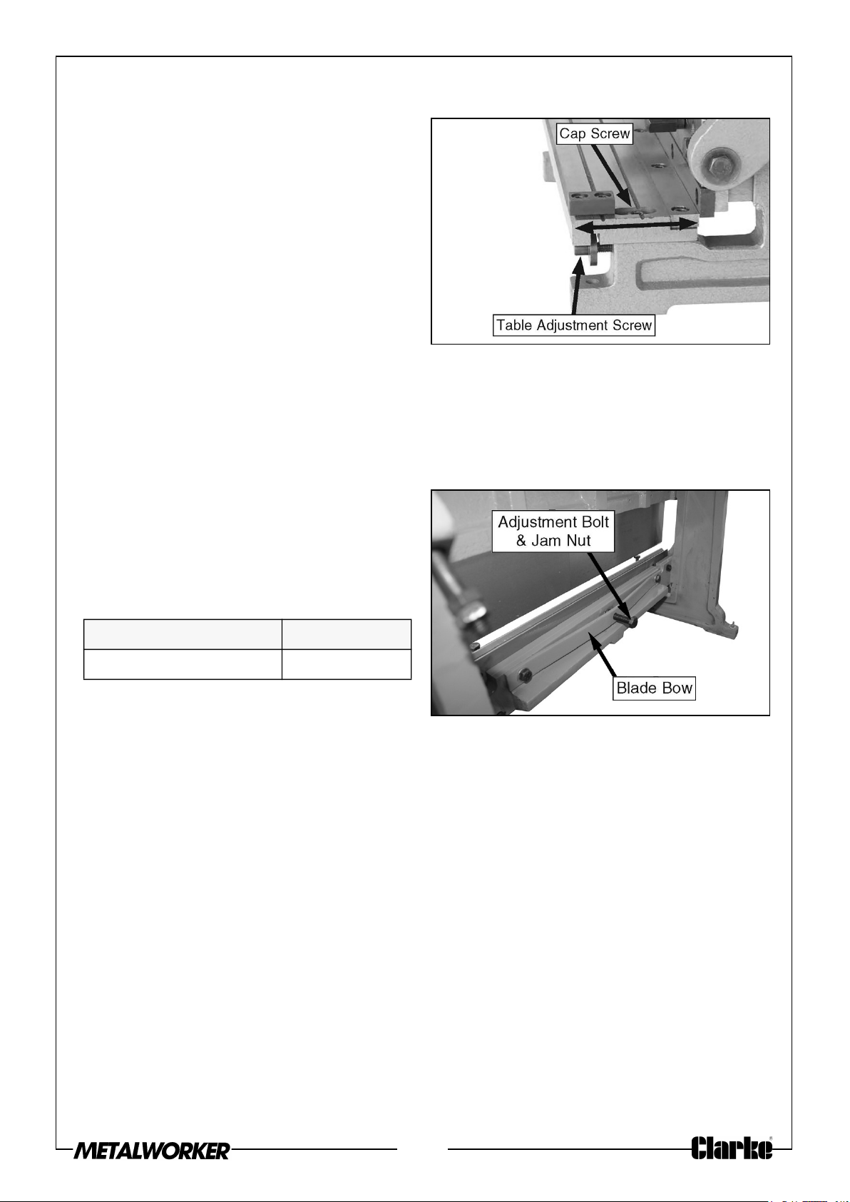
1. Loosen the cap screws on either end
of the shear table that secure it to
the machine (see Figure 48).
2. Evenly rotate the table adjustment
screws to adjust the position of the
shearing table until the blade gap is
even, then re-tighten the cap screws
to secure the table in place.
NOTE: Rotating the table adjustment
screws clockwise moves the
table toward the upper shear blade.
3. Perform the previous shear test.
4. If necessary, repeat Steps 1-3 until you are satisfied with the shear test cut.
ADJUSTING THE BLADE BOW
The adjustment bolt of the blade bow is
used to remove any slight bow in the
cast iron cross beam that the brake
finger receiver and upper shear blade are
attached to (see Figure 49).
Tools Needed Qty
Wrench 14mm 2
Fig. 48
Fig. 49
ADJUSTING THE BLADE GAP WITH THE BLADE BOW:
1. Hold the adjustment bolt still, then turn the jam nut to adjust the center of the
cross beam in or out (see Figure 49).
• If the shear test cut was clean on the ends of the shear table but not in the
middle, turn the jam nut counterclockwise to force the adjustment bolt
against the cross beam, moving it in toward the front.
• If the shear test cut was clean in the middle but not on the ends, rotate the
jam nut clockwise to allow the cross beam to move back.
2. Perform the previous shear test.
3. If necessary, repeat Steps 1-2 until you are satisfied with the shear test cut.
25
Page 26
BRAKE ALIGNMENT
WARNING: THE BRAKE FINGERS ON THIS MACHINE PRESENTS A
PINCHING HAZARD. MAKE SURE NO BODY PART OR CLOTHING IS
NEAR THE AREA WHERE METAL BENDING OCCURS. FAILURE TO
FOLLOW THIS WARNING MAY RESULT IN SEVERE PERSONAL
INJURY.
During the life of your machine you may need to align the brake fingers with the
finger receiver from side-to-side.
Tools Needed
• Hex wrench 6 mm
• Wrench 16 mm
• Heavy flat bar
TO ALIGN THE BRAKE:
1. Remove, clean, and de-burr all of the finger tips and the receiver groove, then
inspect the fingers and receiver for any cracks or damage.
• If any of the brake fingers or the receiver are damaged in any way, DO
NOT use the brake until you have replaced these parts with new ones.
2. Replace the fingers and properly seat them.).
CAUTION: OPERATING THE BRAKE WITH CRACKED OR DAMAGED BRAKE
FINGERS OR RECEIVER COULD CAUSE THESE PARTS TO SHATTER AND FLY
APART, WHICH COULD RESULT IN PERSONAL INJURY.
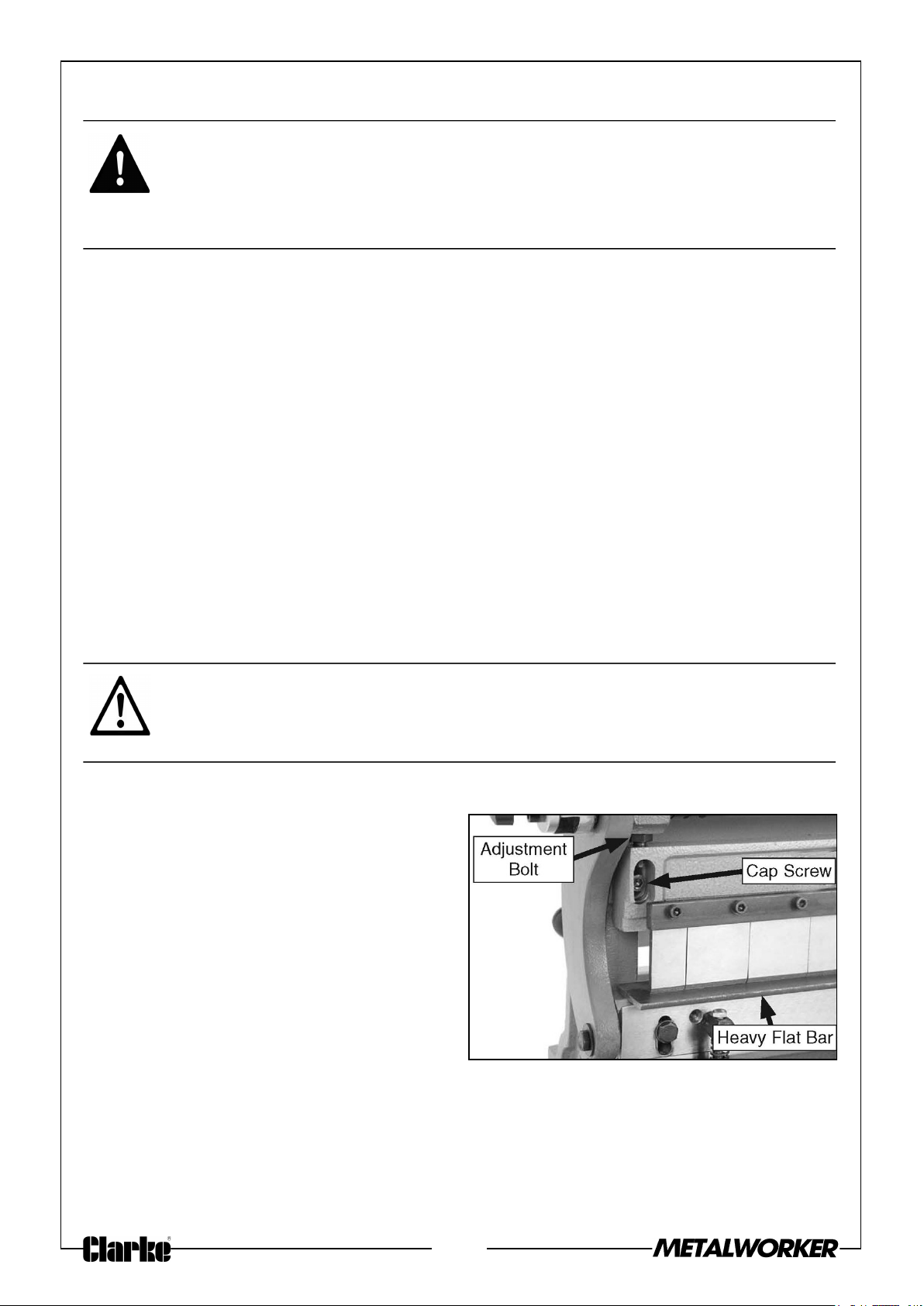
3. Place a piece of heavy flat bar stock
or a heavy metal ruler approximately
12" long across the finger receiver, as
shown in Figure 50.
4. Lower the brake fingers until one just
rests on the metal bar, as shown in
Figure 50.
5. Starting at one end, visually check
the gap between the brake fingers
and the metal bar.
Fig. 50
6. If you find a gap at one end of the brake, loosen the cap screw shown in Figure 50
on that end, then turn the adjustment bolt counterclockwise until the gap
disappears.
7. Re-tighten the cap screw, remove the metal bar and use the hand crank to cycle
the machine 2-3 times.
26
Page 27

8. Repeat steps 3-7 until the brake fingers rest evenly on the metal bar along its
entire length.
27
Page 28
TROUBLESHOOTING
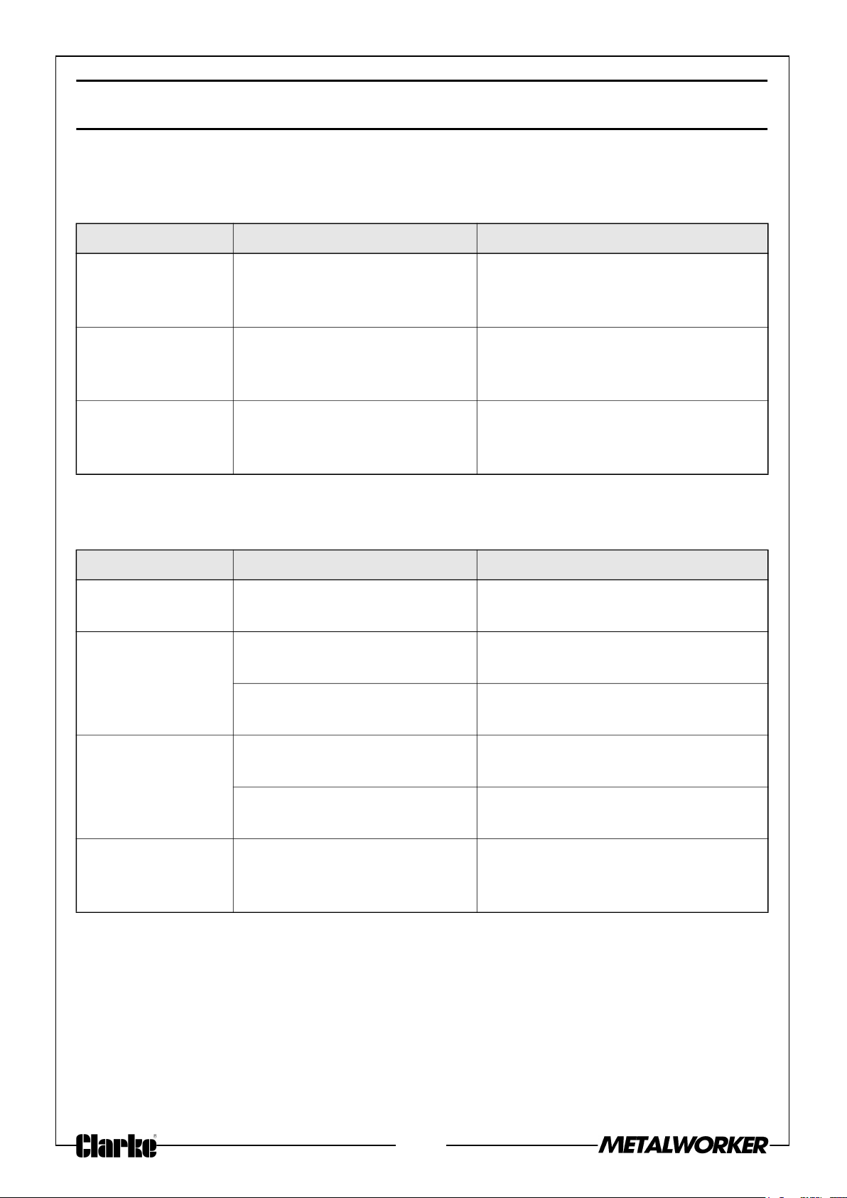
SLIP ROLLER OPERATION
PROBLEM CAUSE SOLUTION
Slip roller creates
cones when trying
to make a cylinder
Creases or
wrinkles in the
workpiece.
Workpiece is
pitted or
scratched
Top and rear rollers not
parallel.
Excessive pressure applied
when rolling.
Workpiece or rollers are dirty
or damaged.
Use the diameter adjustment knobs
to make the rollers parallel.
Reduce the radius and perform the
bend in several light passes.
Thoroughly clean the workpiece
and rollers. Polish out any nicks/
burrs in the rollers or replace them.
BRAKE OPERATION
PROBLEM CAUSE SOLUTION
Heavy resistance
during bending.
Bend radius is not
consistent across
workpiece.
Machine capacities are
exceeded.
Machine capacities are
exceeded.
Fingers and receiver not
aligned.
Operate within the listed capacities
of the machine.
Operate within the listed capacities
of the machine.
Properly align the fingers and
receiver
Tips of brake
fingers are
chipping or rolling.
Workpiece has
scoring marks.
Fingers and receiver not
aligned.
Workpiece is too thick. Operate within the listed capacities
Fingers or receiver scratched Polish out scratches and apply
28
Properly align the fingers and
receiver
of the machine.
tape at the bend locations for
further protection
Page 29
SHEAR OPERATION
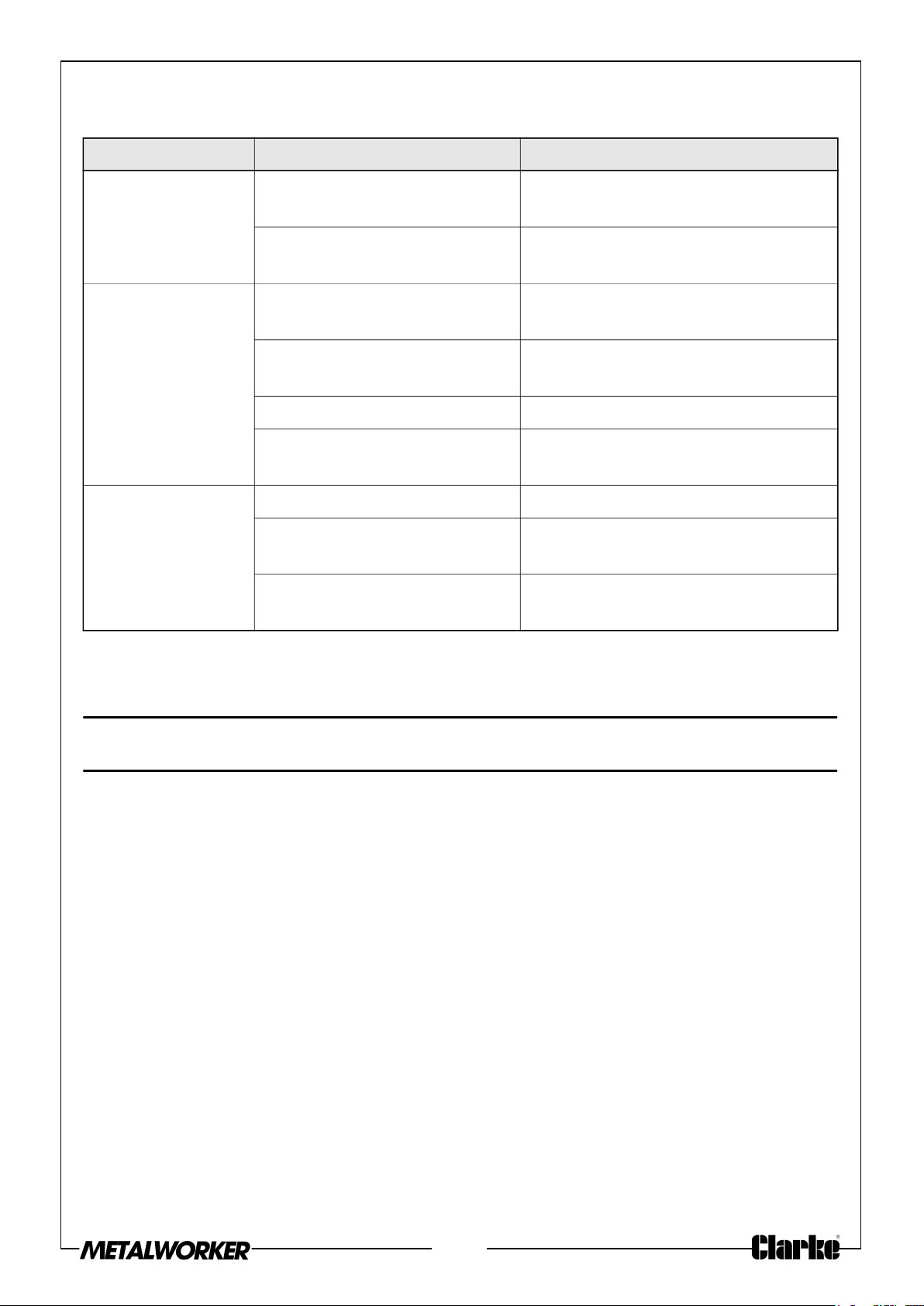
PROBLEM CAUSE SOLUTION
Machine will not
cut workpiece.
Cuts are not
square.
Poor quality of
cuts with ripping
or tearing.
Cut exceeds machine
capacities
Not enough gap between
blades.
Uneven contact with guide or
work stop.
Blade gap unequal across
length.
Too much bow in blade Properly adjust blade bow
Inadequate hold-down
pressure.
Dull blades. Reverse/sharpen/replace blades.
Incorrect blade gap setup. Properly adjust blade gap for
Loose blades. Remove blades, clean thoroughly,
Operate within the listed capacities
of the machine.
Increase blade gap.
Maintain proper contact with guide
and work stop.
Properly adjust blade gap for
material.
Properly adjust hold-down
pressure.
material.
and re-install.
If this does not solve your problem, please contact the CLARKE service department.
GUARANTEE
This product is guaranteed against faulty manufacture for a period of 12 months from
the date of purchase. Please keep your receipt which will be required as proof of
purchase.
This guarantee is invalid if the product is found to have been abused or tampered
with in any way, or not used for the purpose for which it was intended.
Faulty goods should be returned to their place of purchase, no product can be
returned to us without prior permission.
This guarantee does not effect your statutory rights.
29
Page 30
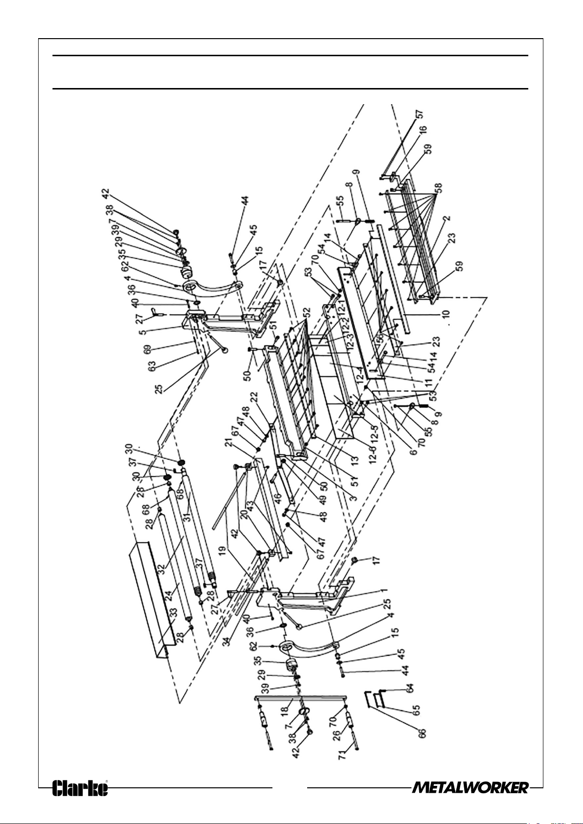
COMPONENT PARTS DIAGRAM
30
Page 31
COMPONENT PARTS
1 LEFT WALL 33 PROTECTING COVER
2 WORK BENCH 34 PRESSING ROLLER LOCK
3 CROSSBEAM 35 ECCENTRIC SHAFT
4 CRANK ARM 36 WASHER
5 RIGHT WALL 37 ROLLER KEY
6 REAR FRAME 38 SCREW M6X12
7 COVER 39 SCREW M6X16
8 PRESS PLATE BRACKET 40 HEX BOLT M6X45
9 SPRING 42 KNOB
10 PRESSING PLATE 43 SCREW M6X8
11 MOVING CUTTER PLATE 44 SCREW M10X55
12.1 UPPER BRAKING DIE 1 INCH 45 WASHER 10MM
12.2 UPPER BRAKING DIE 2 INCH 46 BOLT M12X100
12.3 UPPER BRAKING DIE 3 INCH 47 SCREW M10X25
12.4 UPPER BRAKING DIE 6 INCH 48 WASHER 10MM
12.5 UPPER BRAKING DIE 8 INCH 49 NUT M12
12.6 UPPER BRAKING DIE 10 INCH 50 BOLT M12
13 PRESSING PLATE 51 SCREW M10X35
14 HEX BOLT M10 X 65 52 SCREW M8X30
15 ROLLING WHEEL 53 SCREW M10X30
16 GUIDE 54 WASHER 10MM
17 ADJUSTABLE BOLT 55 SCREW M8X80
18 HANDLE 56 SCREW M6X12
19 POSITIONING BAR 57 SCREW M6X16
20 POSITIONER 58 SCREW M6X12
21 POSITIONING PLATE 59 SCREW M10X20
22 SUPPORTING PLATE 62 OIL CUP
23 CUTTER BLADE 63 PLASTIC HOSE
24 BACK PRESSING ROLLER 64 HEX WRENCH 8MM
25 ROLLER ADJUSTMENT KNOB 65 HEX WRENCH 5MM
26 HANDLE KNOB 66 HEX WRENCH 6MM
27 ADJUSTABLE SCREW 67 NUT M12
28 ROLLER BUSHING 68 PIN
29 WASHER 69 PIN
30 GEAR 70 NUT M10
31 LOWER PRESSING ROLLER 71 BOLT
32 UPPER PRESSING ROLLER
31
Page 32

 Loading...