

Page 1
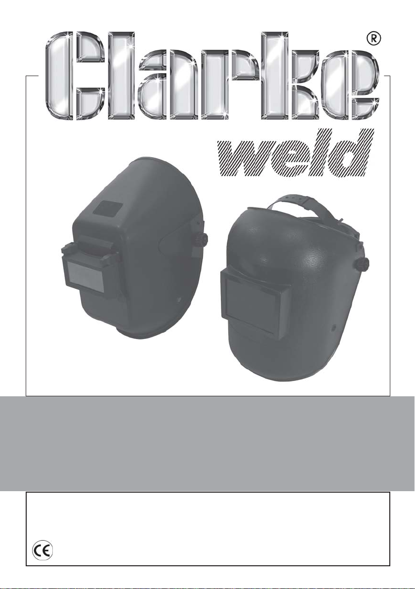
WELDING HEADSHIELDS
Model Nos: PTF1 & PTW1
Part Nos: 6000684 & 6000686
USER & MAINTENANCE
INSTRUCTIONS
GC08/13
Page 2
INTRODUCTION
Thank you for purchasing this CLARKE Welding Headshield.
Please read this manual thoroughly and follow the instructions given. In doing
so you will ensure the safety of yourself and that of others around you, and
you can look forward to the product giving you long and satisfactory service.
GUARANTEE
This product is guaranteed against faulty manufacture for a period of 12
months from the date of purchase. Please keep your receipt which will be
required as proof of purchase.
This guarantee is invalid if the product is found to have been abused or
tampered with in any way, or not used for its intended purpose. Faulty goods
should be returned to their place of purchase, no product can be returned to
us without prior permission.
This guarantee does not effect your statutory rights.
ENVIRONMENTAL PROTECTION
If broken, do not dispose of this product with general household waste. This
product contains valuable raw materials and should be disposed of
appropriately at a recognised disposal facility.
SPECIFICATIONS
1WTP 1FTP
thgieWtcudorPg013g705
)HxW(dleiFgniweiVmm28x801mm24x79
noitcetorPRI/VU11NID11NID
erutarepmeTgnitarepOxaM55
Parts & Service: 020 8988 7400/E-mail:[email protected] or [email protected]
O
C55OC
2
Page 3
GENERAL SAFETY WARNINGS
• The protective lens in this headshield is breakable and will not protect
against impact hazards.
• This headshield is designed for use in arc welding or cutting applications
such as MIG/MAG, TIG, MMA, Plasma Arc, and Carbon Arc.
• Use this headshield for face and eye protection against harmful rays,
sparks and spatter from welding and cutting.
• This headshield is not suitable for laser welding, laser cutting or
“overhead” welding applications, or for oxyacetylene.
• Never place this product on a hot surface.
• Do not make any modifications to this product. Protection can be seriously
impaired if modifications are made.
• When necessary, use identical replacement parts. This will ensure that the
safety of the product is maintained.
• Only trained welders should use this product.
• Do not use without protective lens cover installed. Do not use if any part of
the headshield is cracked or broken.
• Do not use this headshield for welding above the range of DIN 11. Harm
to the eyes and impaired eyesight may result.
• Always use the mask for the duration of exposure to hazards. Stop work if
dizziness or eye irritation occurs or if the mask becomes damaged.
Please keep these instructions in a safe place for future reference.
PREPARATION & USE
CONTENTS
1 x Welding Headshield 1 x Adjustable Headband
1 x Dark Glass Filter (fitted) 2 x Protective Glasses (PTF1)
1 x Protective Glass (PTW1)
Refer to the part numbers on pages 5 and 6.
ASSEMBLY-PTW1
1. Install headband (9) by passing the studs (5) through the holes on the sides
of the headband from inside. Ensure square lugs of the studs sit in the holes
and place the adjustment tabs (6) over the studs while inside the
headshield.
3
Parts & Service: 020 8988 7400/E-mail:[email protected] or [email protected]
Page 4
2. Pass the the studs through the holes in the headshield and secure both
sides with the securing knobs (7). Ensure that corresponding holes in the
adjustment tabs sit on the positioning pins (11).
3. If already fitted, remove the lens retainer from the headshield and also
remove the protective film from the glass lens before use.
4. Position both the outer and inner lenses (2 & 3) in the headshield recess
before securing, by clipping in the lens retainer (4).
ASSEMBLY-PTF1
1. Install the headband (9) by passing the studs (5) through the openings in
the headband from the inside. Pass the adjustment tab over the studs and
pass the studs though the holes in the headshield. Screw the knobs onto
the studs from outside the headshield, ensuring the holes in the adjustment
tabs sit on the positioning pin (11).
2. Raise the flip-up filter lens holder and remove the protective film from the
lens before use. Position both the outer and inner lenses (2 & 3) in the flipup lens holder and secure by clipping in the lens retainer (4).
ADJUST HEADBAND TO FIT
The headband should be adjusted both in diameter and height to fit the
wearer’s head. To do this:
1. Press the adjustment knob (8) on the back of the headband and turn the
nut either left or right to expand or contract the headband.
2. The top headband can be adjusted by bending the strap and positioning
the peg in the appropriate hole.
CARE AND MAINTENANCE
GENERAL
Damaged components must be replaced immediately to avoid risk of eye
and face injuries. Periodically inspect the lenses. Cracked, pitted or
scratched lenses reduce vision and seriously reduce level of protection and
should be replaced with genuine, certified spare parts. The outer lens can be
removed for cleaning or replacement after prising out the lens retainer.
CLEANING & STORAGE
The headshield should be stored in it’s box or similar place.
Clean all lenses with a soft tissue and suitable lens cleaning fluid. Do not use
solvents. Never use tools or other sharp objects to remove material from the
lens or headshield. This may cause damage which may impair function and
invalidate the warranty.
4
Parts & Service: 020 8988 7400/E-mail:[email protected] or [email protected]
Page 5
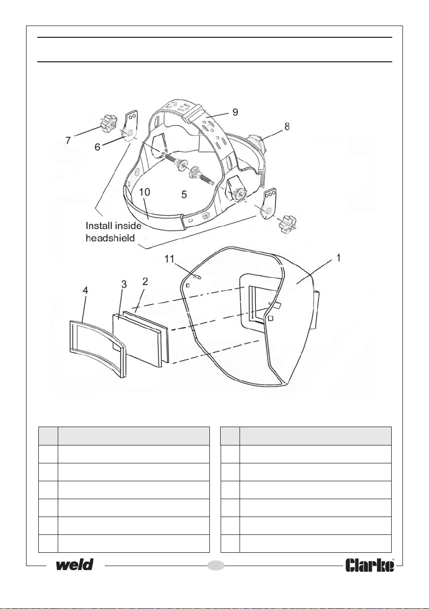
COMPONENT PARTS - PTW1
oN noitpircseD oN noitpircseD
1llehSdleihsdaeH7bonKgniruceS
2sneLretuOssalGevitcetorP8bonKtnemtsujdAdnabdaeH
3)detar11NID(sneLren
nI9dnabdaeH
4reniateRsneL01dnaBtaewS
5dutSgnitcennoC11niPgninoitisoP
6baTgnitsujdA
5
Parts & Service: 020 8988 7400/E-mail:[email protected] or [email protected]
Page 6
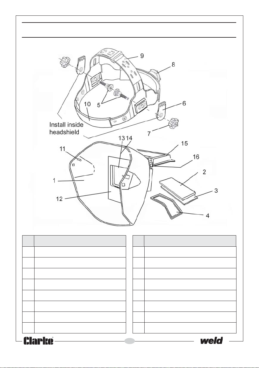
COMPONENT PARTS - PTF1
oN noitpircseD oN noitpircseD
1llehSdleihsdaeH9dnabdaeH
2sneLretuOssalGevitcetorP01dnaBtaewS
3)detar11NID(sneLrennI11niPgninoitisoP
4reniateRsneL21lenaPrennI
5dutSgnitcennoC31sneLyradnoceS
6baTgnitsujdA41reniateRsneLyradnoceS
7bonKgniruceS51redloHs
8bonKtnemtsujdAdnabdaeH61niPegniHpalF
6
Parts & Service: 020 8988 7400/E-mail:[email protected] or [email protected]
neLpu-pilF
Page 7
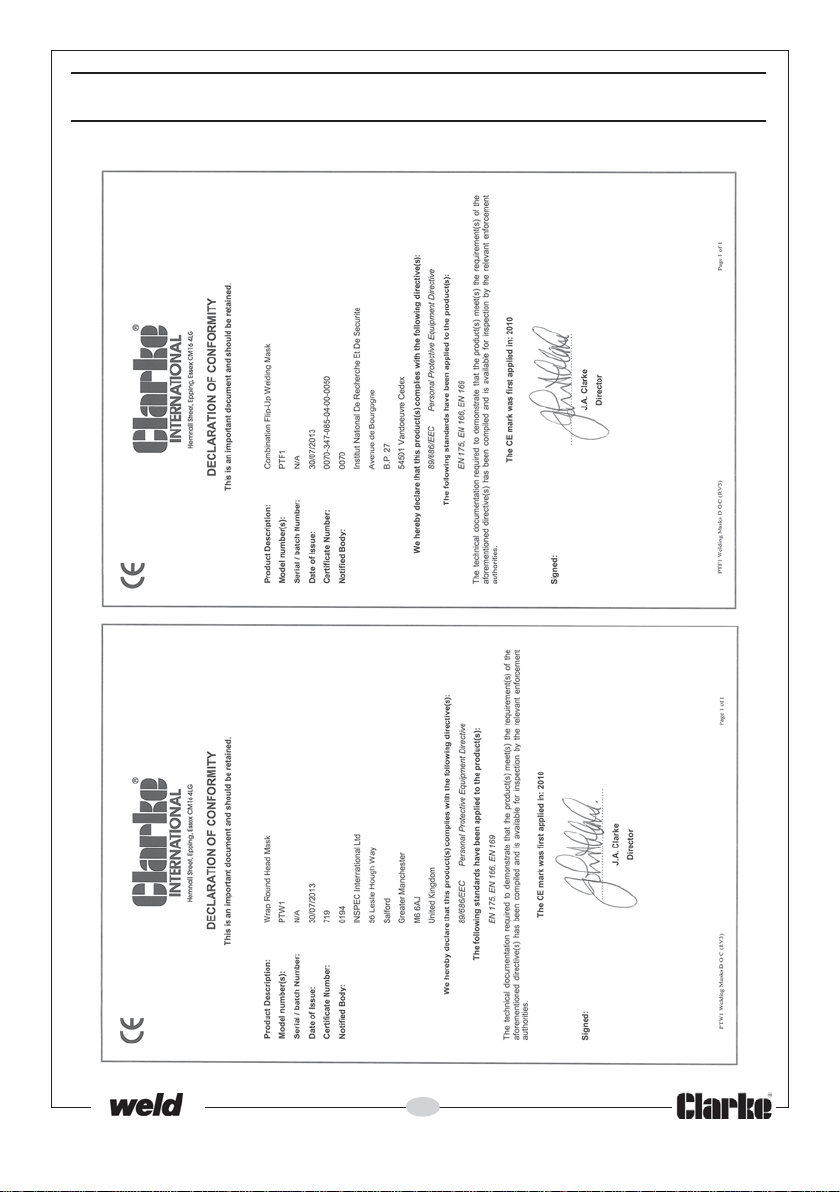
DECLARATION OF CONFORMITY
7
Parts & Service: 020 8988 7400/E-mail:[email protected] or [email protected]
Page 8

 Loading...