

Page 1
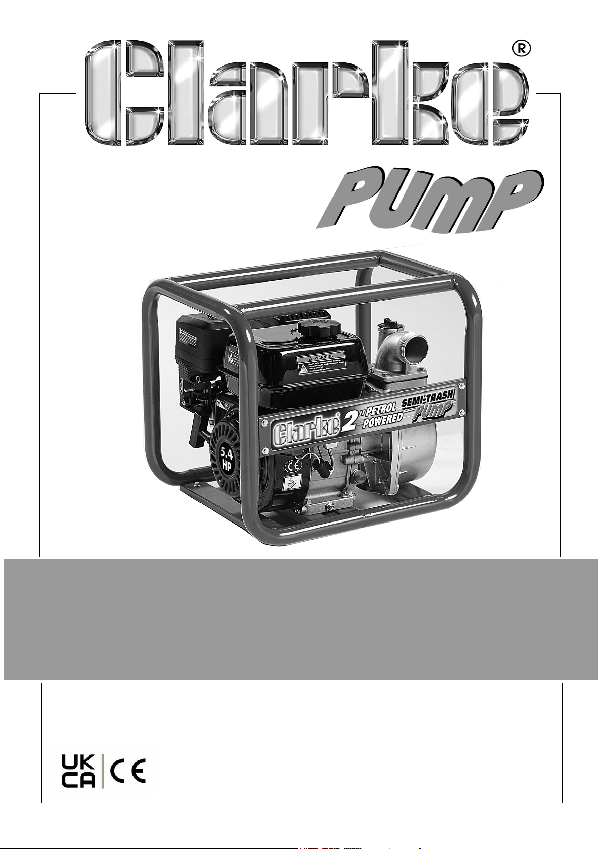
ENGINE DRIVEN SEMI TRASH 2” PUMP
MODEL NO: PS50
PART NO: 7230167
OPERATION & MAINTENANCE
INSTRUCTIONS
ORIGINAL INSTRUCTIONS
GC1124
Page 2
INTRODUCTION
Thank you for choosing this CLARKE Pump. Before attempting to use this product,
please read this manual thoroughly and follow the instructions carefully. In doing so
you will ensure the safety of yourself and that of others around you, and you can look
forward to your purchase giving you long and satisfactory service.
The function of this pump is to move clean /dirty water (with solids in suspension up
to 15 mm in diameter).
DO NOT use it to pump:
•Sewage
• Dangerous liquids - (Flammable or corrosive)
• Salt water
Before you use this pump read the manual fully.
GUARANTEE
This pump is guaranteed against faulty manufacture for a period of 12 months from
the date of purchase.
Please keep your receipt which will be required as proof of purchase.
This guarantee is invalid if the pump has been abused, tampered with, or not used for
its primary function.
Faulty goods must be returned to their place of purchase, no pump can be returned to
us without prior permission.
This guarantee does not effect your statutory rights.
INVENTORY
You should find the items in the list below in the carton.
1 x Petrol Powered 2" Water Pump 2 x Rubber Sealing Rings
2 x 2" BSP Inlet/outlet fittings 1 x Spark Plug Box Wrench
1 x Plastic x Inlet Strainer (in two pieces) 6 x Hose Clips
Speak to your CLARKE dealer If items are missing or damaged.
2
Parts & Service: 020 8988 7400 / E-mail: [email protected] or [email protected]
Page 3
GENERAL SAFETY RULES
WARNING: WHEN USING PUMPS, ALWAYS FOLLOW BASIC SAFETY
PRECAUTIONS TO REDUCE THE RISK OF FIRE, ELECTRIC SHOCK AND
PERSONAL INJURY. READ ALL INSTRUCTIONS BEFORE YOU
OPERATE THIS PUMP AND SAVE THEM FOR FUTURE REFERENCE.
1. ALWAYS obey all safety precautions for the handling of fuel.
2. ALWAYS make sure that you are familiar with this pump, and follow all
instructions in this manual.
3. ALWAYS make sure that the pump is positioned correctly to prevent it from
moving during operation.
4. Keep the area adjacent to the pump clear.
5. ALWAYS connect the strainer to the suction hose to stop stones and other solids
from being pulled into the pump. These can cause damage to the pump.
6. ALWAYS keep the pump dry and clear of discharge hose.
7. Only use parts supplied by the manufacturer. Using non-standard parts can be
dangerous.
8. ALWAYS use at least 300mm of flexible hose to make plumbing connections to
the pump. Rigid piping can put stress on the pump, causing damage. If you use
rigid piping, it must be supported to eliminate stress on the connections.
9. DO NOT refuel the engine while it is operating and let the engine cool sufficiently
before refuelling.
10. DO NOT use to pump petrol (or other flammable liquids), or corrosive chemicals.
The function of this pump is to pump WATER ONLY.
11. DO NOT operate this pump in an explosive atmosphere, near combustible
materials, or where there is insufficient ventilation.
12. DO NOT let children use this pump.
13. DO NOT run the pump dry. ALWAYS fill the pump with water before starting.
14. DO NOT direct the discharge flow towards another person.
15. DO NOT over-tighten drain or filler plugs. Excessive force can damage the
threads or the pump body.
16. DO NOT direct the water discharge towards electrical wiring or equipment.
3
Parts & Service: 020 8988 7400 / E-mail: [email protected] or [email protected]
Page 4
GENERAL SAFETY IN THE WORKPLACE
1. ALWAYS keep work area clean & tidy. Cluttered work areas invite accidents.
2. NEVER over-reach. Keep proper footing and balance at all times.
3. ALWAYS make sure that the workplace is well lit. Make sure that that lighting is
placed so that you will not be working in your own shadow.
4. Dress correctly. Loose clothing or jewellery can get caught in moving parts. Nonslip footwear is recommended. Wear protective hair covering to contain long hair.
5. ALWAYS wear safety glasses. (Everyday glasses are not safety glasses).
CARE OF PUMPS
1. The CLARKE service department can replace damaged components.
2. ALWAYS examine the pump for damage that can effect the operation of the
pump. Repair any damaged parts.
3. Have your pump repaired by a qualified person. Repairs must only be carried out
by qualified persons using original spare parts.
Keep the instructions for future reference.
SAFETY SYMBOLS
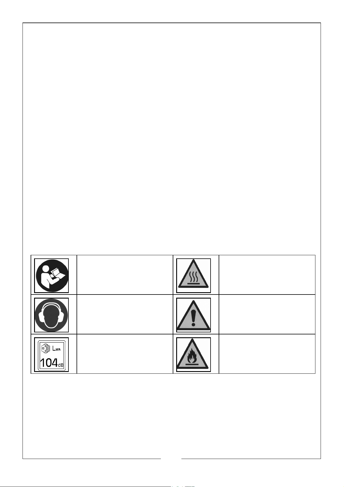
The meanings of the markings and symbols on the pump are shown below
Read this manual before use
and keep it for future
reference
Wear ear protection when
in operation
WARNING: Loud noise
when in operation
WARNING: Hot surfaces
WARNING: Adhere to
safety information on label
WARNING: Flammable
substances
4
Parts & Service: 020 8988 7400 / E-mail: [email protected] or [email protected]
Page 5
ASSEMBLY
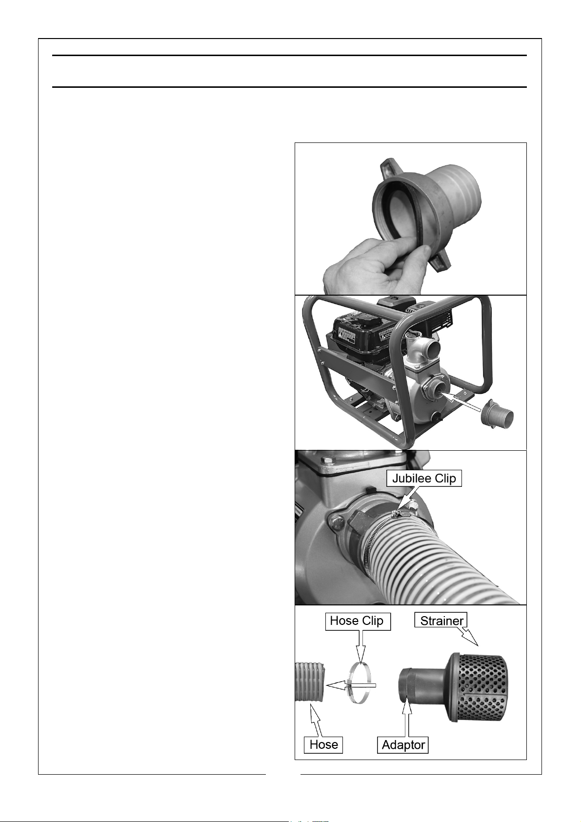
INSTALL THE SUCTION HOSE
1. Fit the rubber washer into the
adaptor making sure that it is seated
correctly.
2. Screw the adaptor onto the pump
securely.
3. Slide the hose on to the adaptor and
lock in position with the jubilee clip
supplied.
4. Install the strainer on to the other
end of the hose using the other clip
supplied.
5
Parts & Service: 020 8988 7400 / E-mail: [email protected] or [email protected]
Page 6
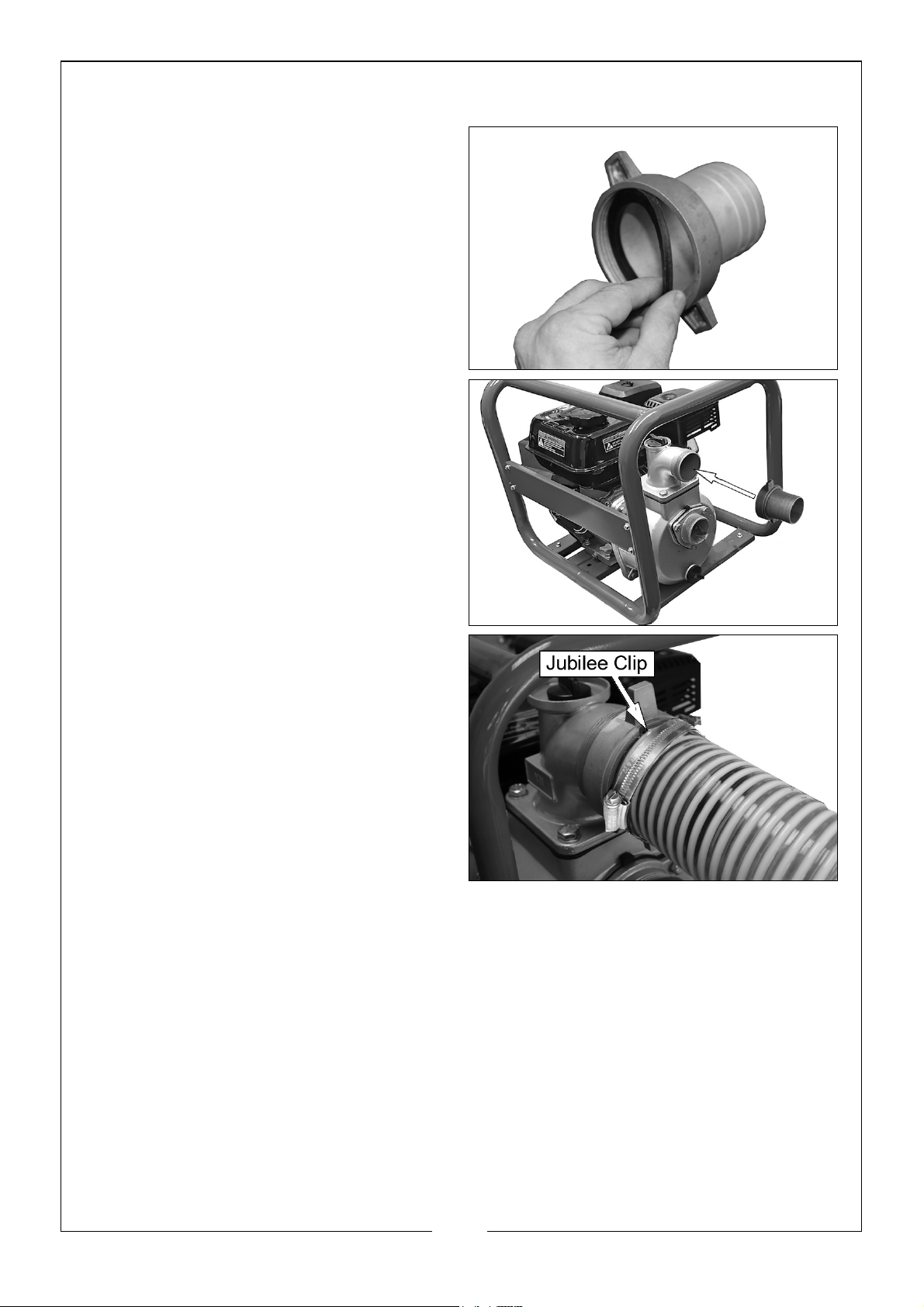
INSTALL THE DISCHARGE HOSE
1. Fit the rubber washer into the other
adaptor making sure it is seated
correctly.
2. Screw the adaptor onto the pump
securely.
3. Slide the hose on to the adaptor and
lock in position with the jubilee clip
supplied.
6
Parts & Service: 020 8988 7400 / E-mail: [email protected] or [email protected]
Page 7
BEFORE USE
PUMP PLACEMENT
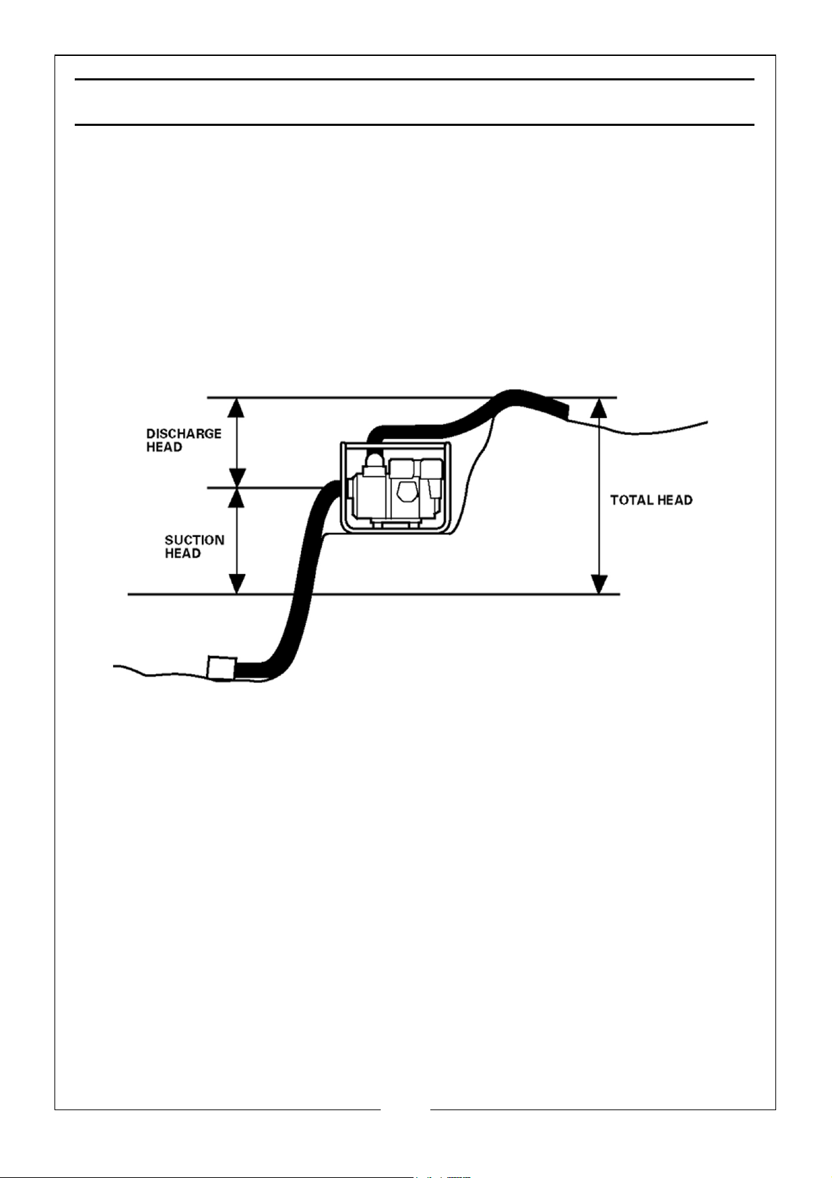
For best pump performance, place the pump near the water level, and use hoses that
are no longer than necessary. That will enable the pump to produce the greatest
output with the least self-priming time.
As head (pumping height) increases, pump output decreases. The length, type, and
size of the suction and discharge hoses can also significantly affect pump output.
Discharge head capability is always greater than suction head capability, so it is
important for suction head to be the shorter part of total head
7
Parts & Service: 020 8988 7400 / E-mail: [email protected] or [email protected]
Page 8
CHECKING/FILLING THE ENGINE OIL BEFORE USE
WARNING: TO DO THIS CHECK, PUT THE PUMP ON LEVEL GROUND
WITH THE ENGINE SWITCHED OFF.
WARNING: TAKE CARE NOT TO TOUCH ANY HOT PARTS OF THE
PUMP WHEN CHECKING THE OIL LEVEL.
NOTE: The pump will normally be shipped without oil in the engine and will
require filling before use.
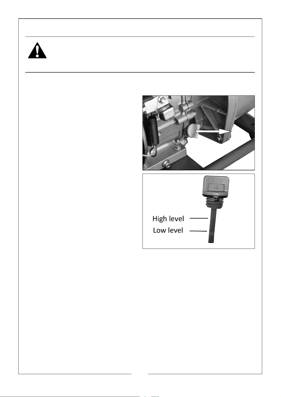
1. Turn the oil filler cap anti-clockwise
and remove from the oil fill tube.
2. Clean the dipstick with a clean cloth.
3. Put the dipstick into the oil fill tube
and then remove it again. DO NOT
screw in the oil filler cap/dipstick
when doing this.
4. If the oil level is at or below the ‘L’
mark on the dipstick, add oil to the
crankcase.
• Fill until the oil touches the
threads in the oil fill tube.
• Oil capacity (See page 20).
• We recommend that you use
CLARKE SAE10W30 oil (Part No:
3050845) in this pump available
from your CLARKE dealer.
5. Replace the oil filler cap.
8
Parts & Service: 020 8988 7400 / E-mail: [email protected] or [email protected]
Page 9
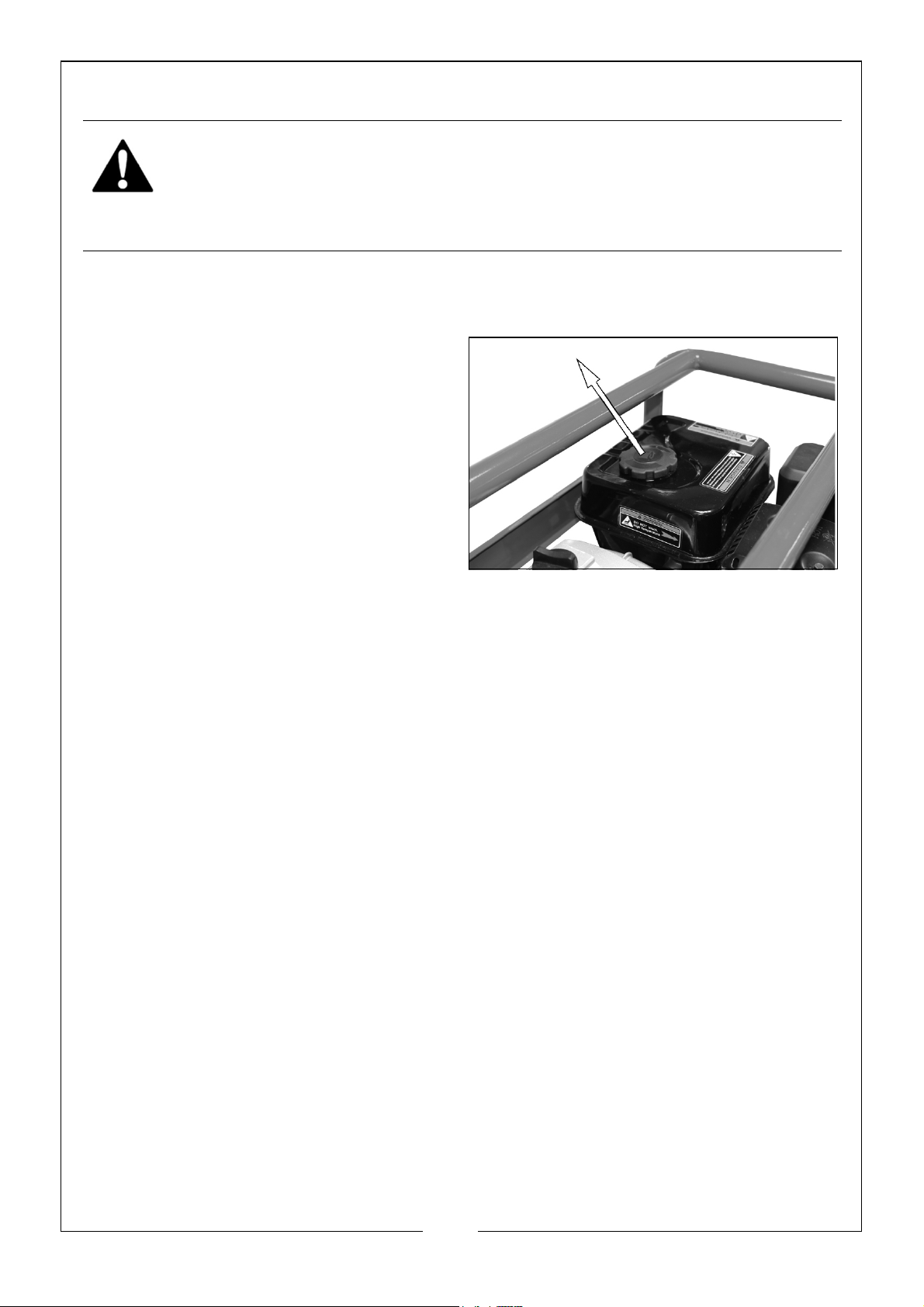
ADD FUEL
WARNING: REFUEL IN A VENTILATED AREA, AWAY FROM SOURCES
OF IGNITION.
WARNING: IF THE ENGINE IS HOT, LET IT COOL BEFORE REFUELING.
WARNING: KEEP FUEL OUT OF THE REACH OF CHILDREN.
RECOMMENDED FUEL
Only use unleaded petrol.
1. Remove the fuel tank cap.
• In the fuel tank is a fuel filter
which collects contaminants as
you refuel.
2. Carefully add fuel to the fuel tank.
• Make sure that the fuel filter is
free of contamination.
• The max capacity of fuel is 3.6L.
3. Replace the fuel tank cap.
9
Parts & Service: 020 8988 7400 / E-mail: [email protected] or [email protected]
Page 10
OPERATION
WARNING: WHEN YOU OPERATE THE PUMP, THE EXHAUST MUFFLER
WILL BE VERY HOT.
WARNING: DO NOT OPERATE THE ENGINE IN A CLOSED SPACE,
MAKE SURE THAT THERE IS SUFFICIENT AIRFLOW AROUND THE
PUMP DUE TO HARMFUL EMMISSIONS/ FUMES FROM THE ENGINE.
PRIME THE PUMP
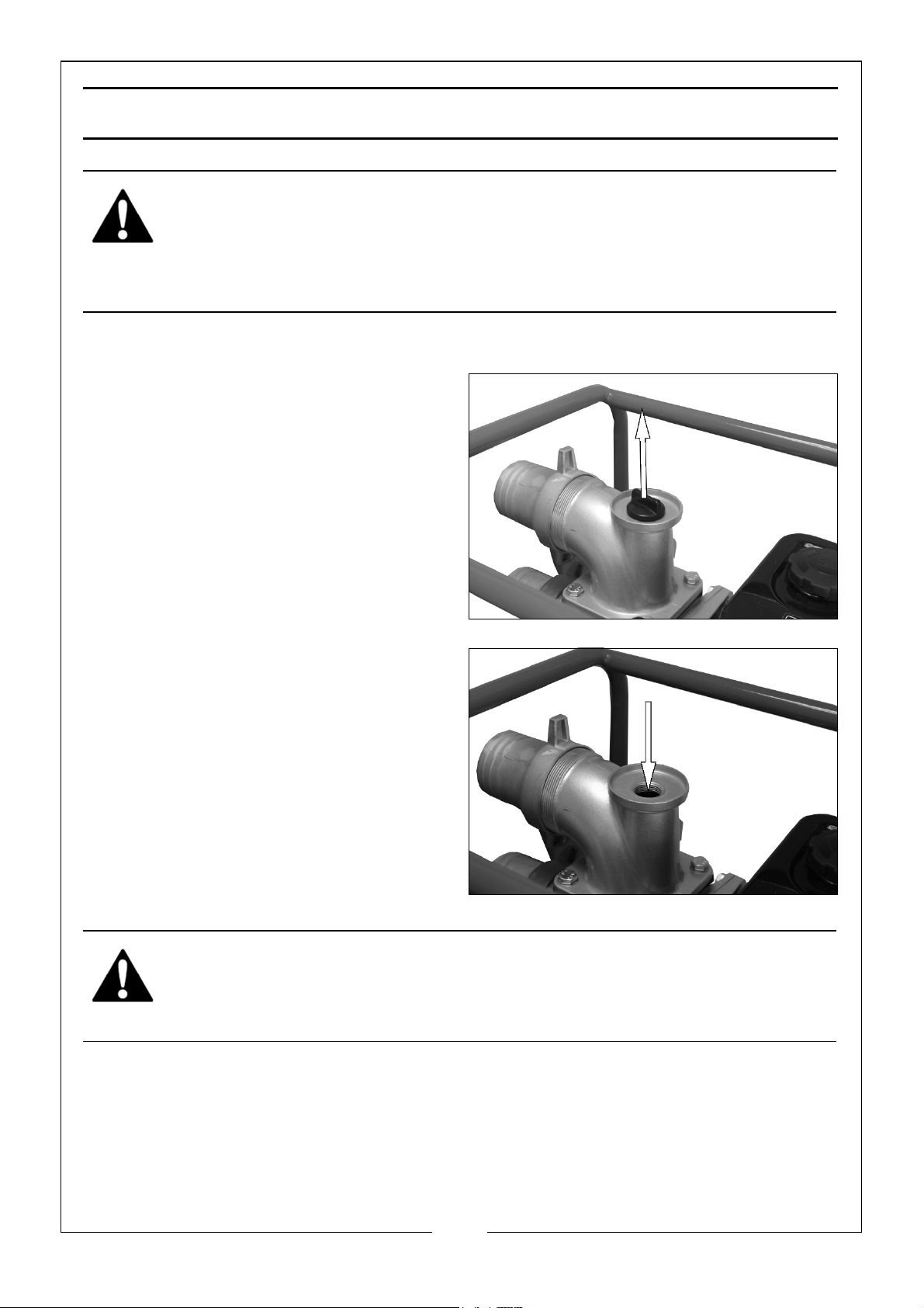
The pump must be primed before use.
1. Before starting the engine, remove
the filler cap from the pump chamber.
2. Fill the pump chamber and inlet hose
with water.
NOTE: A foot valve (not supplied)
connected to the lower end of
the inlet hose between the
hose and the strainer will help
to maintain priming,
3. Replace the filler cap and tighten it
securely.
WARNING: OPERATING THE PUMP DRY WILL DESTROY THE PUMP
SEAL. IF THE PUMP IS OPERATED DRY, STOP THE ENGINE
IMMEDIATELY AND LET THE PUMP COOL BEFORE PRIMING
10
Parts & Service: 020 8988 7400 / E-mail: [email protected] or [email protected]
Page 11
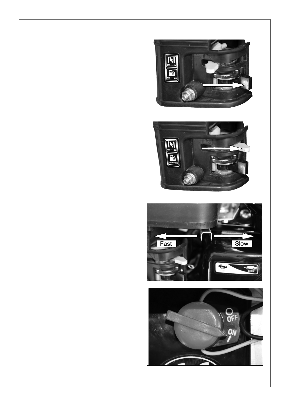
STARTING THE ENGINE
1. Set the fuel valve to the ON position.
2. To start a cold engine, move the
choke lever to the ‘ON’ position.
• To restart a warm engine, move
the choke lever to the ‘OFF’
position.
3. Move the throttle lever away from
Slow about 1/3 of the way.
4. Set the engine switch to ‘ON’.
11
Parts & Service: 020 8988 7400 / E-mail: [email protected] or [email protected]
Page 12
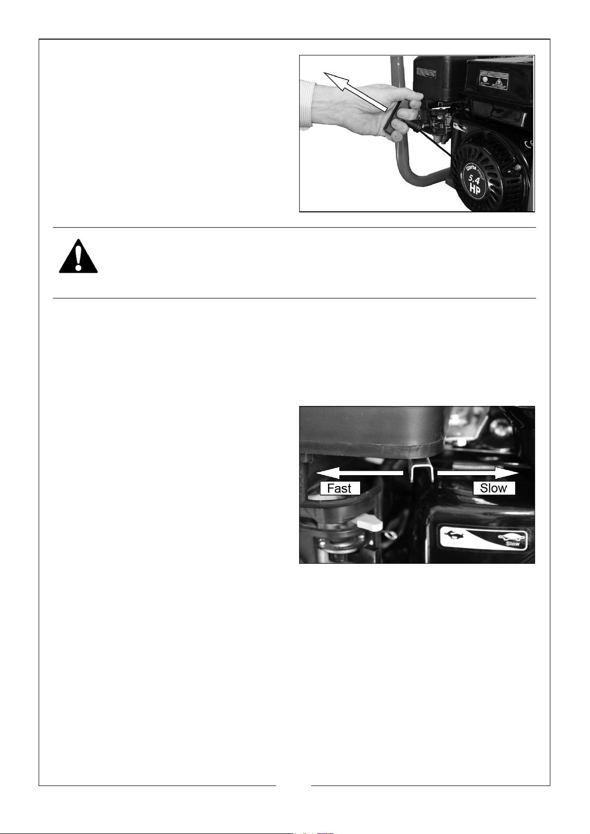
5. Pull the starting handle lightly until
you start to feel resistance. Then pull
up and away suddenly to start the
engine.
NOTE: You might need to do this more
than once.
WARNING: WHEN THE PUMP HAS STARTED, RELEASE THE STARTING
HANDLE SLOWLY TO PREVENT INJURY/DAMAGE AS IT RETURNS.
6. Once the engine has warmed up from a cold start, move the choke lever to the
‘OFF’ position.
SETTING THE ENGINE SPEED
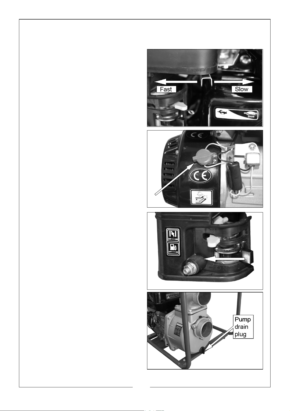
After starting the engine, move the throttle lever to the FAST position for self-priming
and check pump output.
Pump output is controlled by adjusting
engine speed.
• Moving the throttle lever in the
FAST direction will increase pump
output.
• Moving the throttle lever in the
SLOW direction will decrease
pump output.
12
Parts & Service: 020 8988 7400 / E-mail: [email protected] or [email protected]
Page 13
SHUTTING DOWN THE PUMP
To stop the pump in an emergency, set the engine switch to ‘OFF’.
1. Use the throttle lever to decrease
engine speed to minimum.
2. Set the engine switch to “OFF”.
3. Turn the fuel valve to “OFF”.
AFTER USE
1. Remove the pump drain plug and
drain the pump chamber.
2. Remove the filler cap and flush the
pump chamber with clean, fresh
water.
• Allow the water to drain from the
pump chamber.
3. Reinstall the filler cap and drain plug.
13
Parts & Service: 020 8988 7400 / E-mail: [email protected] or [email protected]
Page 14
MAINTENANCE
CLEARING BLOCKAGES
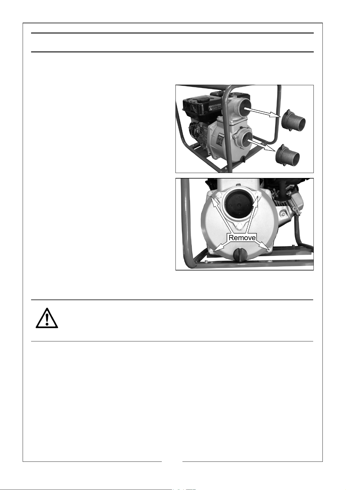
1. Remove the hoses and adaptors from
the pump.
2. Remove the four bolts shown in the
picture.
3. Remove the front cover.
4. Clear debris and clean the inner parts
using clean water.
5. Replace the front cover and secure
using the four bolts removed in step
2.
CHANGING THE ENGINE OIL
CAUTION: PROLONGED EXPOSURE TO USED ENGINE OIL IS DANGEROUS,
ALWAYS WASH YOUR HANDS THOROUGHLY AFTER HANDLING USED
ENGINE OIL.
Change the oil in the engine after the first 20 hours use and thereafter every 6
months or 100 running hours.
1. Unscrew and remove the oil filler cap/dipstick.
14
Parts & Service: 020 8988 7400 / E-mail: [email protected] or [email protected]
Page 15
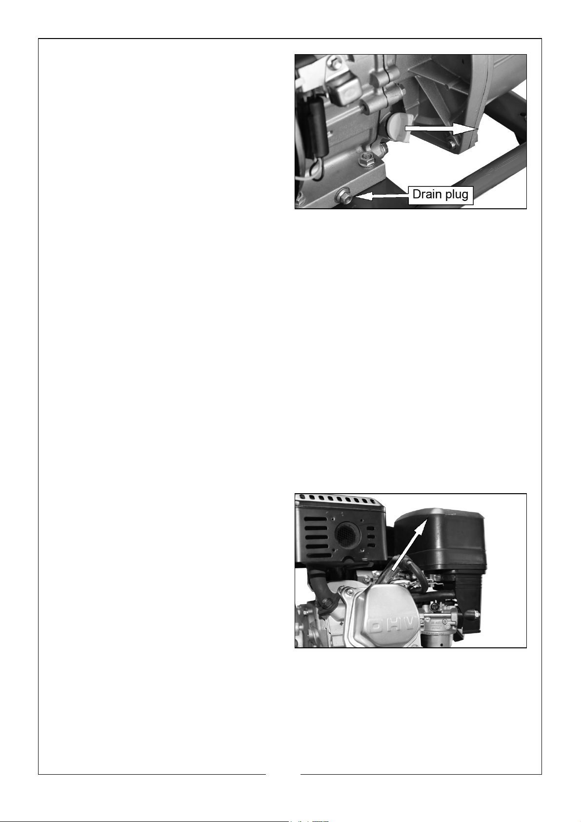
2. Put a oil collection tray below the
drain plug.
3. Unscrew the drain plug and let the
used engine oil drain from the
crankcase into the oil collection tray.
NOTE: Drain the engine oil when the
engine is warm, this will make
sure that the oil flows out
faster.
4. Replace the drain plug.
5. Fill the crankcase with engine oil.
• Fill until the oil touches the threads in the oil fill tube.
• Oil capacity (0.6 L).
• We recommend that you use CLARKE SAE10W30 oil (Part No: 3050845) in
this pump available from your CLARKE dealer.
6. Replace the oil filler cap/dipstick.
ENVIRONMENTAL PROTECTION
One of the most damaging sources of pollution is oil, DO NOT throw away or pour it
down drains. Put it in a leak proof container and take it to your local waste disposal
site.
CHANGING THE SPARK PLUG
Replace the spark plug after the first month or every 50 hours of use.
1. Remove the spark plug cap from the
spark plug.
15
Parts & Service: 020 8988 7400 / E-mail: [email protected] or [email protected]
Page 16
2. Use the spark plug spanner supplied
to remove the spark plug.
3. Remove any carbon that has
collected around the electrode.
4. Check the spark plug gap (a), it
should be between 0.7 and 0.8 mm,
adjust if necessary.
5. Check the overall condition of the
spark plug for erosion or pitting and
replace if necessary.
6. Reinstall the spark plug and replace
the spark plug cap.
CHANGING THE AIR FILTER
Clean the air filter after 50 hours of operation (or more often in unusually dusty
conditions) as follows.
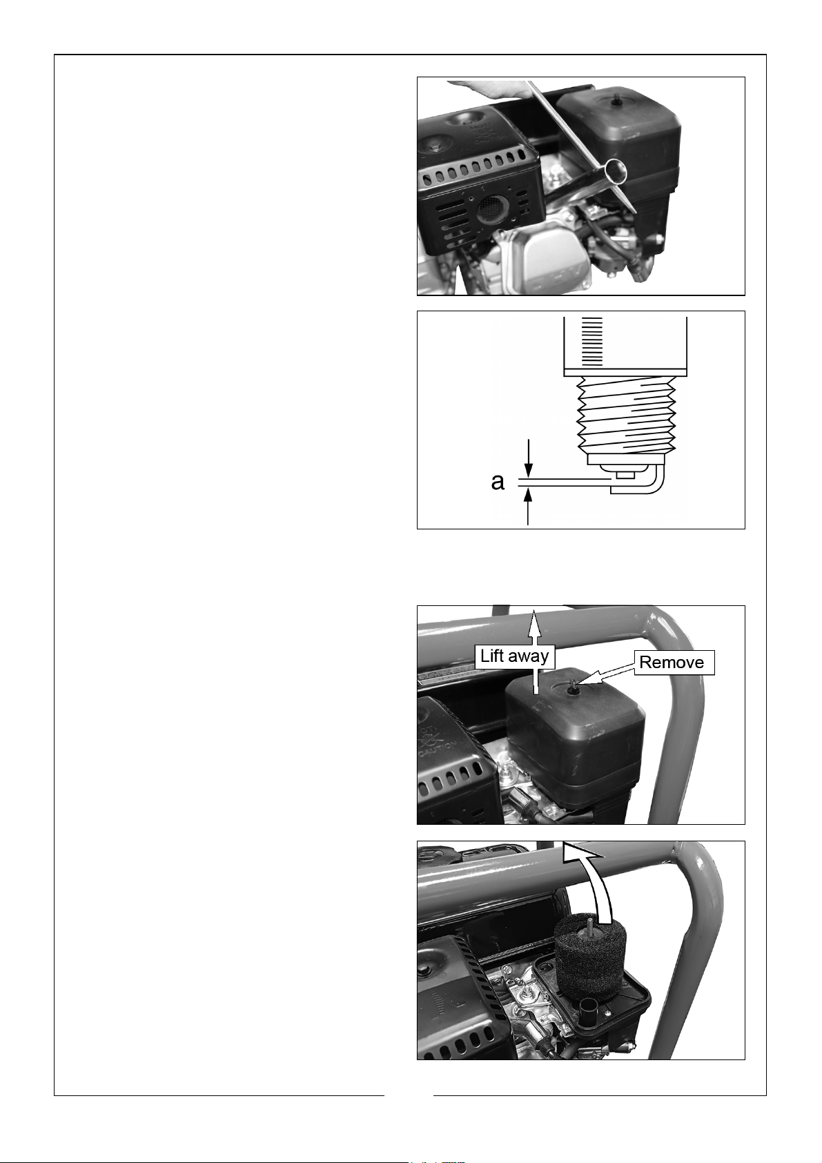
1. Unscrew the wingnut and lift off the
air filter cover.
2. Remove the air filter element.
3. Clean the air filter or replace if
necessary.
• If the filter is dirty, wash the filter
in a solution of warm water and
mild detergent and rinse
thoroughly. Leave the filter to dry
completely,
16
Parts & Service: 020 8988 7400 / E-mail: [email protected] or [email protected]
Page 17

4. Once it is dry, Dip in clean engine oil and squeeze out excess oil.
• DO NOT operate the pump without the air cleaner installed as this will
cause premature wear to the engine.
STORAGE
1. Always keep the pump in a dust and damp free environment away from children.
MAINTENANCE RECORD
OIL CHANGE:
____________________________________________________________
____________________________________________________________
____________________________________________________________
____________________________________________________________
SPARK PLUG CHANGE:
____________________________________________________________
____________________________________________________________
____________________________________________________________
____________________________________________________________
AIR FILTER CHANGE:
____________________________________________________________
____________________________________________________________
____________________________________________________________
____________________________________________________________
MISCELLANEOUS:
____________________________________________________________
____________________________________________________________
____________________________________________________________
____________________________________________________________
17
Parts & Service: 020 8988 7400 / E-mail: [email protected] or [email protected]
Page 18
TROUBLESHOOTING
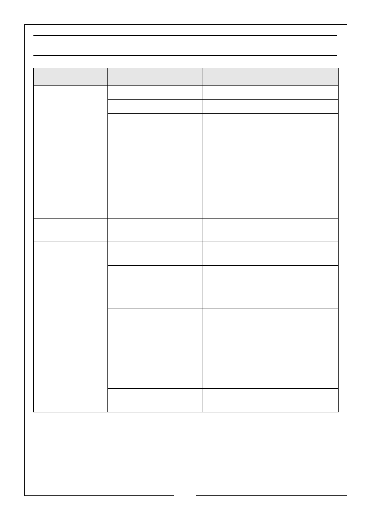
PROBLEM CAUSE SOLUTION
The engine does
not start.
The engine stops
and will not restart.
The pump fails to
prime.
No fuel in tank. Add fuel.
Fuel valve is set to OFF Set the fuel valve to ON.
Engine switch is in the
OFF position.
Lack of spark at the
spark plug.
No fuel in tank. Add fuel to the tank.
Priming chamber not
filled correctly.
Air leaking due to
damaged hose, broken
hose clamps, split/illfitting gasket.
Set engine switch to the ON
position.
Make sure that the spark plug cover
is fitted on to the plug.
With the engine switch in the ON
position, hold the spark plug
electrode against the engine and pull
the starter cord. If a spark is present
but engine will not start, consult your
CLARKE dealer.
Fill priming chamber leaving no air
gap.
Repair as necessary.
Blocked inlet hose. Clean strainer and make sure that it
is not submerged in mud or
sediment. Make sure that there are
no kinks in the delivery hose.
Engine speed too low. Increase engine speed.
Damaged impeller. Disassemble the pump and replace
the impeller.
Air leaking through
damaged seal.
18
Parts & Service: 020 8988 7400 / E-mail: [email protected] or [email protected]
Replace seal.
Page 19
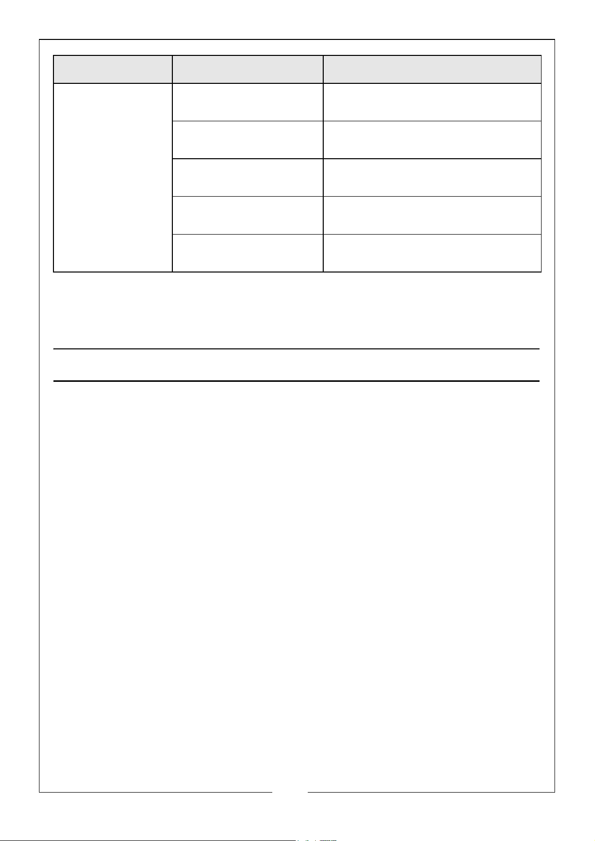
PROBLEM CAUSE SOLUTION
Low output from
pump.
If you cannot correct the fault, speak to your local dealer or the CLARKE International
service department.
The engine speed is too
low.
Pickup or delivery hose
obstructed.
Suction lift too high. Set the pump nearer to the water
Congested material
inside pump.
Damaged impeller. Disassemble the pump and replace
Increase the engine speed.
Clear obstruction and make sure that
there are no kinks in hose.
level.
Disassemble the pump and clean out.
the impeller.
ENVIRONMENTAL PROTECTION
At the end of its working life, DO NOT discard this pump or its components with
general household waste. Packaging must be taken to a recycling centre and
discarded appropriately.
One of the most dangerous sources of pollution is oil. DO NOT discard used oil with
domestic refuse or flush down a sink or drain. Collect the oil in a leak-proof container
and take it to your local waste disposal site.
19
Parts & Service: 020 8988 7400 / E-mail: [email protected] or [email protected]
Page 20
SPECIFICATION
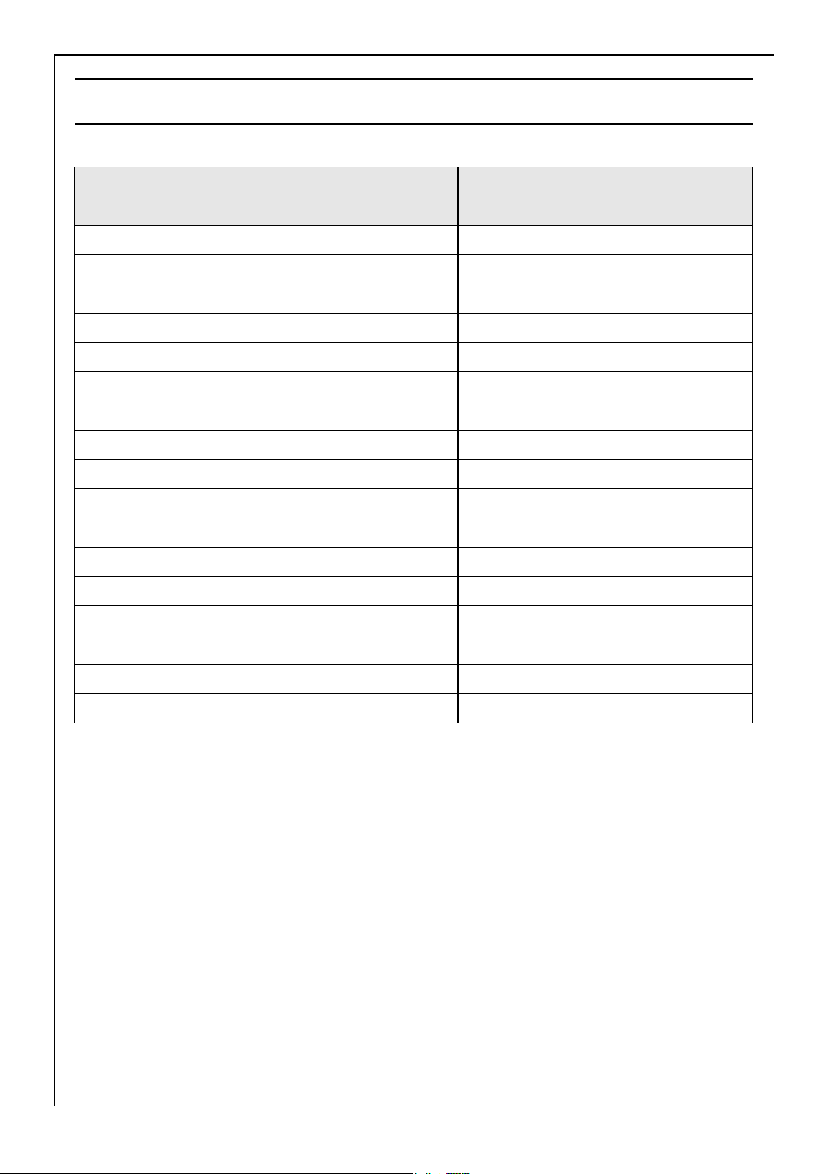
Item Specification
Model No PS50
Pump Dimensions (L X W X H) 505 x 405 x 440 mm
Pump Weight (Kgs) 22 kg
Water Classification Semi-dirty water
Max Solids In Suspension 15 mm
Inlet/outlet Size 2” BSP
Maximum Flow 450l/min
Rated Head 28 m
Suction Head 7-8 m
Max Pressure 2.8 bar
Engine power 5.4HP
Fuel Tank Capacity (Petrol) 3.6 L
Fuel consumption 1.8L/hr
Lubrication Oil Capacity/grade 0.6 L (SAE 15W40)
Sound Pressure Level 87.95 dB LpA
Sound Power Level 101.1 dB LWA
Guaranteed Sound Power Level 104 dB LWA
Uncertainty Factor (K) 2.5 dB
20
Parts & Service: 020 8988 7400 / E-mail: [email protected] or [email protected]
Page 21
COMPONENT PARTS
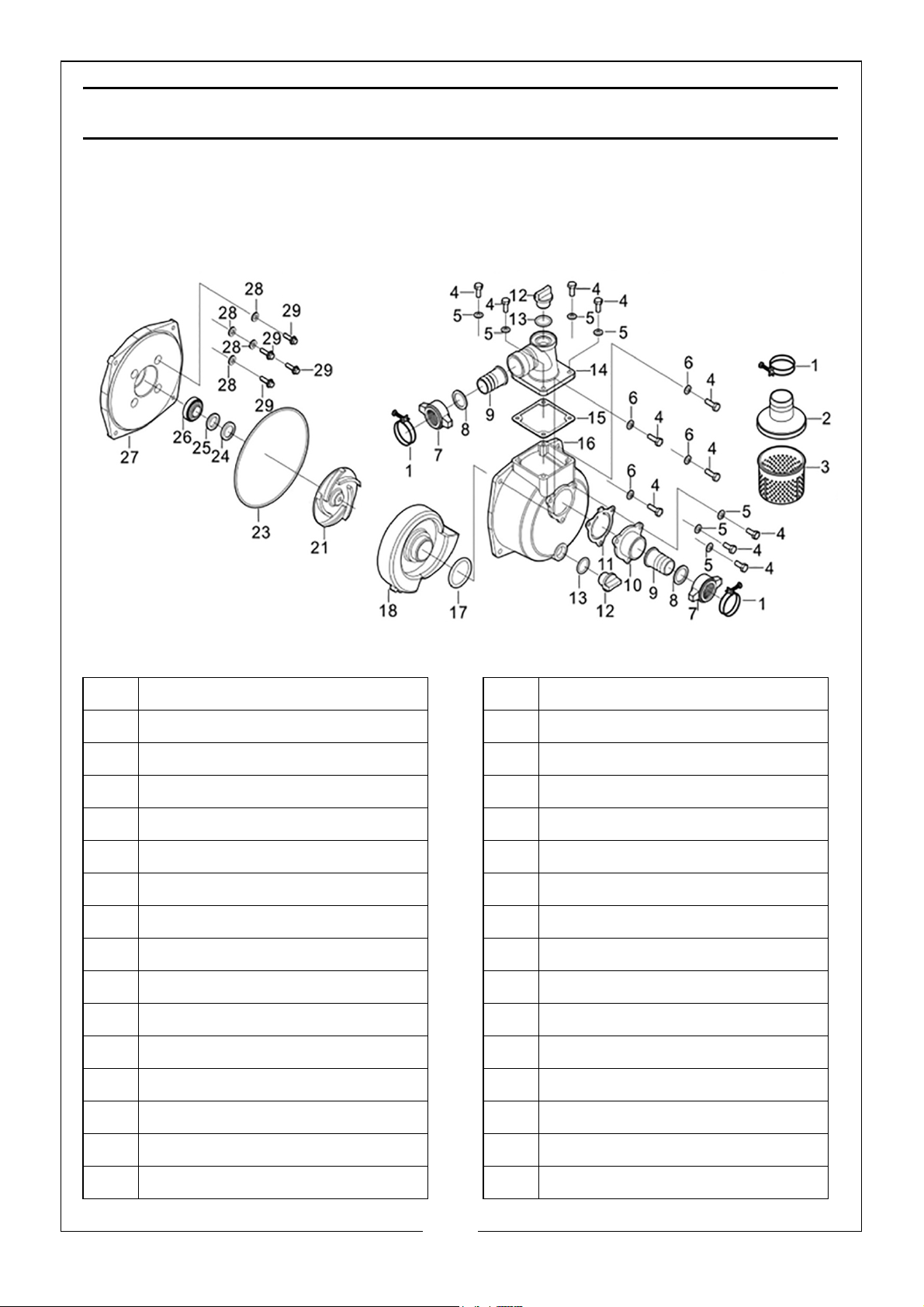
A full set of engine parts list and diagrams are available from the CLARKE
International service department.
WATER PUMP ASSEMBLY
No Description No Description
1 Hose clip 16 Pump body
2 Filter cover 17 Case sealing
3 Filter body 18 Casing
4Bolt 19N/A
5Washer 20N/A
6 Washer 21 Impeller
7 Adaptor ring nut 22 n/a
8 Hose seal connector 23 Pump joint gasket
9 2” pipe connector 24 Seal
10 Water inlet 25 Porcelain seal
11 Water inlet gasket 26 Seal assembly
12 Plug 27 Pump end plate
13 Washer for plug 28 Washer
14 Water outlet elbow 29 Bolt
15 Outlet gasket 30 Pump assembly complete
21
Parts & Service: 020 8988 7400 / E-mail: [email protected] or [email protected]
Page 22
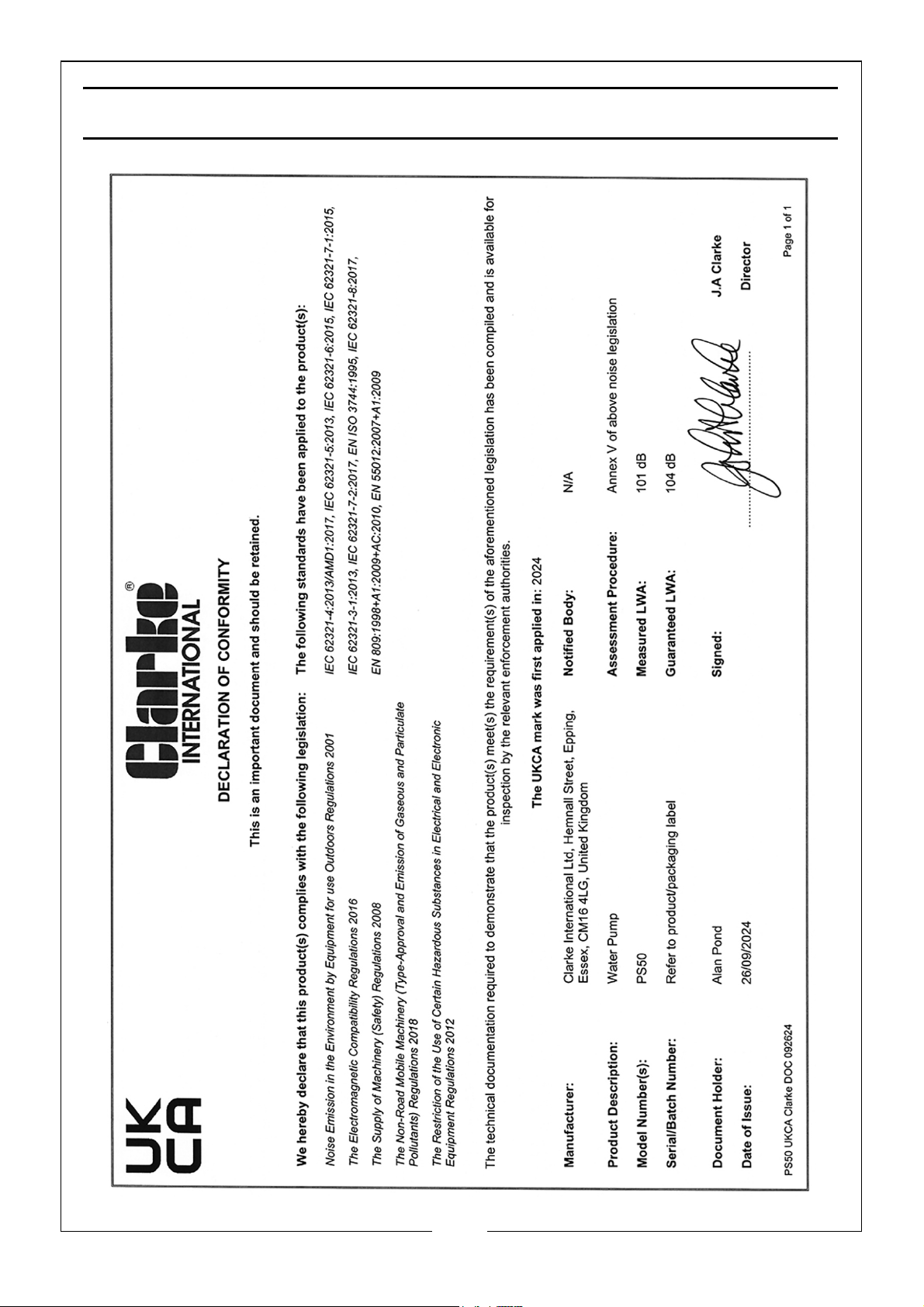
DECLARATIONS OF CONFORMITY -UK
22
Parts & Service: 020 8988 7400 / E-mail: [email protected] or [email protected]
Page 23
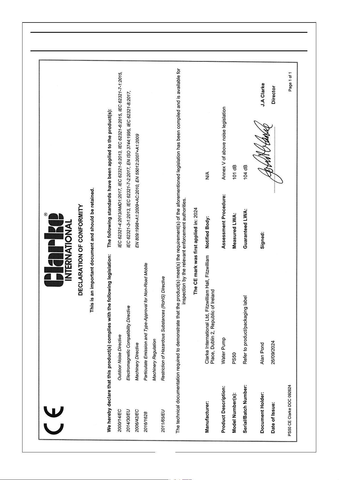
DECLARATIONS OF CONFORMITY -CE
23
Parts & Service: 020 8988 7400 / E-mail: [email protected] or [email protected]
Page 24

 Loading...