

Page 1
OPERATION & MAINTENANCE
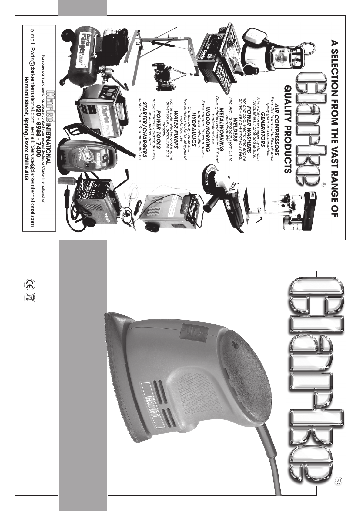
PALM SANDER
PALM SANDER
INSTRUCTIONS
0705
MODEL NO: PS105
PART No: 6462055
Page 2
Please note that the details and specifications contained herein, are correct at the time of going to print. However,
CLARKE International reserve the right to change specifications at any time without prior notice.
-1- -10-
disposed of according to all local ordinances
When disposing of this product, ensure it is
determined.
used, per day.
reference.
Some tools with a high vibration value, such as impact wrenches, are generally used for a few
seconds at a time, therefore the cumulative time may only be in the order of a few minutes per
day. Nevertheless, the cumulative effect, particularly when added to that of other hand held
power tools that may be used, must always be taken into account when the total daily dose rate is
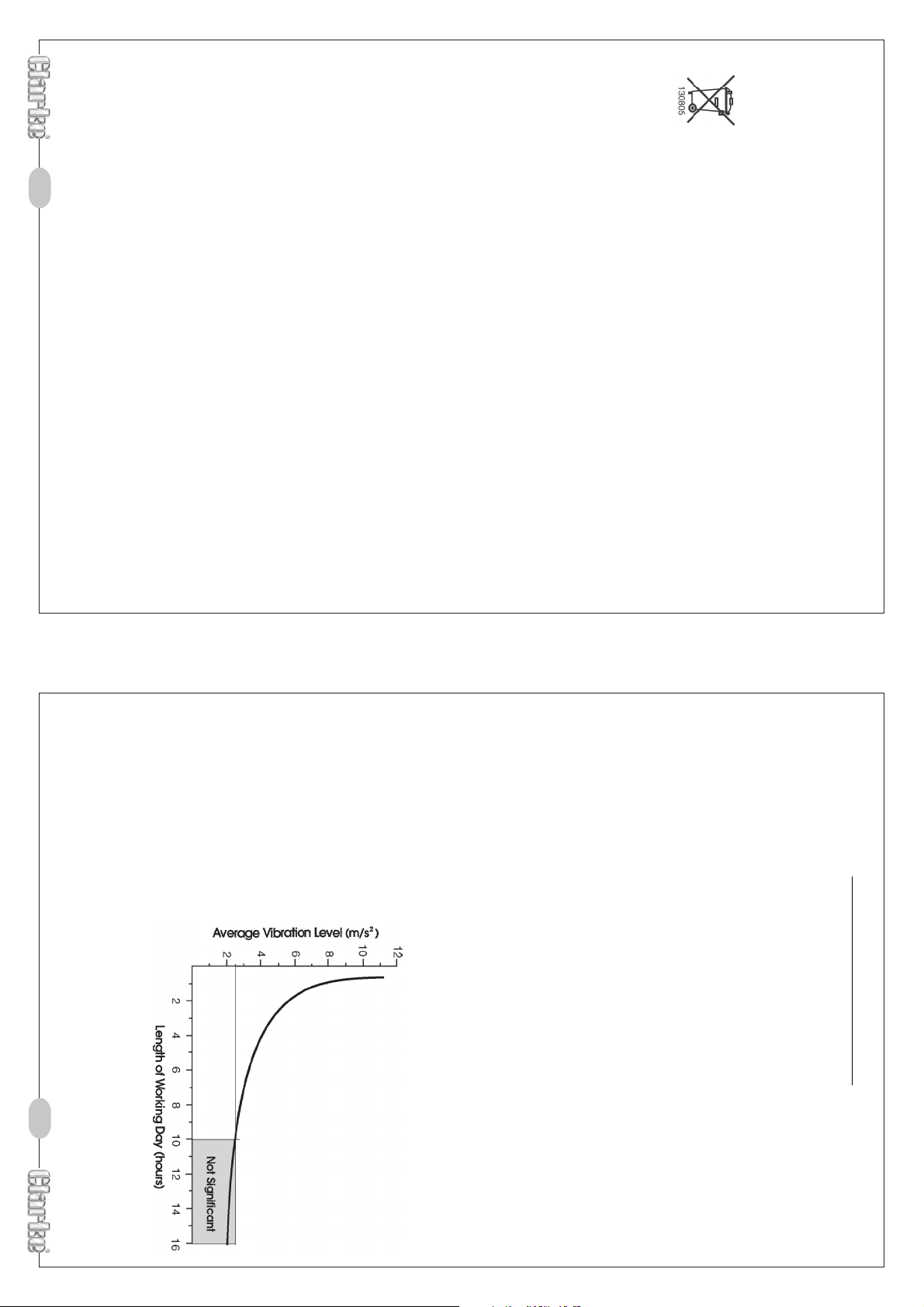
tool with a vibration value of 2.8 m/s
whereas a tool with a value of 11.2 m/s
The graph below shows the vibration value against the maximum time the respective tool may be
2
2
may be used for up to 8 hours (cumulative) per day,
may be used for ½ hour per day only.
single plane. This is the maximum level of vibration measured during testing in one of the axes,
and this should also be taken into account when making a risk assessment.
‘a’ values in excess of 2.5 m/s
2
are considered hazardous when used for prolonged periods. A
which represents the uncertainty factor, i.e. a value in excess of ‘a’, to which the tool could
vibrate under normal conditions. These values appear in the declaration on page 7.
You will note that a third value is given in the specification - the highest measured reading in a
The uncertainty factor should also be
taken into account when assessing a
risk. The two figures ‘a’ and ‘K’may
be added together and the resulant
value used to assess the risk.
It should be noted that if a tool is used
under abnormal, or unusual
conditions, then the vibration level
could possibly increase significantly.
Users must always take this into
account and make their own risk
assessment, using the graph as a
All hand held power tools vibrate to some extent, and this vibration is transmitted to the operator
via the handle, or hand used to steady the tool. Vibration from about 2 to 1500 herz is potentially
damaging and is most hazardous in the range from about 5 to 20 herz.
Operators who are regularly exposed to vibration may suffer from Hand Arm Vibration Syndrome
(HAVS), which includes ‘dead hand’, ‘dead finger’, and ‘white finger’. These are painful
conditions and are widespread in industries where vibrating tools are used.
The health risk depends upon the vibration level and the length of time of exposure to it……in
effect, a daily vibration dose.
Tools are tested using specialised equipment, to approximate the vibration level generated under
normal, acceptable operating conditions for the tool in question. For example, a grinder used at
45° on mild steel plate, or a sander on softwood in a horizontal plane etc.
These tests produce a value‘a’, expressed in metres per second per second, which represents the
average vibration level of all tests taken, in three axes where necessary, and a second figure ‘K’,
Employers are advised to refer to the HSE publication “Guide for Employers”.
HAND-ARM VIBRATION
Page 3
-9-
Values determined according to EN28622-1
Declared vibration emmission value in accordance
Measured vibration emmission value -
Uncertainty value -
Highest measured reading in a single plane m/s
DESCRIPTION: PS105
MODEL No: Palm Sander
Refer to notes on page 10
HAND-ARM VIBRATION
Accessories: (Accessory/Replenishment Pack)
2
Check List
Dimensions LxWxH: ...................................... 160x98x132mm
This Product Conforms To 98/37/EEC regulations
K:
8.7 m/s
Weight: ......................................................... 0.95kg
Noise level: ................................................... 70 dB(A)
a:
6.8 m/s
2
2
No Load Speed: .......................................... 12000 rpm
Pad SizeLxW: ................................................ 140x99mm
with EN12096
Model No: .................................................... PS105
Part No: ........................................................ 6462055
Voltage: ........................................................ 230vac~ 50Hz
Power: .......................................................... 105w
with in any way, or not used for the purpose for which it was intended.
Faulty goods should be returned to their place of purchase, no product can be
returned to us without prior permission.
This guarantee does not effect your statutory rights.
Specifications
This CLARKE product is guaranteed against faulty manufacture for a period of 12
months from the date of purchase. Please keep your receipt as proof of purchase.
This guarantee is invalid if the product is found to have been abused or tampered
Thank you for purchasing this CLARKE Palm sander, which has been designed for DIY use
only.
Before attempting to use the sander, please read this manual thoroughly and follow the
instructions carefully. In doing so you will ensure the safety of yourself and that of others
around you, and you can look forward to the tool giving you long and satisfactory service.
-2-
Scrubbing Pad 1off
Wire Wool Pad 1off
Foam Pad 1 off
120 grit 5off
80 grit 5off
Sanding Sheets 60 grit 5off
Instruction Manual
Palm Sander
CLARKE GUARANTEE
Page 4
-3- -8-
11. ALWAY S ensure the switch is off before plugging in to mains. Avoid
13. ALWAY S keep your proper footing and balance at all
times - don’t overreach. For best footing, wear rubber
soled footwear. Keep floor clear of oil, scrap wood,
etc.
12. ALWAY S concentrate on the job in hand, no matter
accidental starting.
how trivial it may seem. Be aware that accidents are
caused by carelessness due to familiarity.
10. ALWAY S handle with extreme care do not carry the tool/machine
by its’ electric cable, or yank the cable to disconnect it from the
power supply.
8. ALWAY S keep children away. All visitors should be kept a
9. ALWAY S maintain machine in top condition. Keep tools/machines
safe distance from the work area, especially whilst operating the machine.
clean for the best and safest performance. Follow maintenance
instructions.
7. ALWAY S ensure that adequate lighting is available. A
condition that may affect the machines operation. Any damage should be properly
repaired or the part replaced. If in doubt, DO NOT use the machine. Consult your
local dealer.
when changing accessories.
Everyday eyeglasses do not have impact resistant lenses, they are not safety glasses.
benches invite accidents.
minimum intensity of 300 lux should be provided. Ensure
that lighting is placed so that you will not be working in
your own shadow.
4. ALWAY S disconnect the tool/machine from the power supply before servicing and
5. ALWAY S wear safety goggles, manufactured to the latest European Safety Standards.
6. ALWAY S keep work area clean. Cluttered areas and
2. ALWAY S use a face or dust mask if operation is particularly dusty.
3. ALWAY S check for damage. Before using the machine, any
damaged part, should be checked to ensure that it will operate
properly, and perform its intended function. Check for alignment
of moving parts, breakage of parts, mountings, and any other
1. ALWAY S Learn the machines applications, limitations and the
specific potential hazards peculiar to it. Read and become familiar
with the entire operating manual.
ignored, personal injury to the operator or damage to property, may result.
As with all machinery, there are certain hazards involved with their operation
and use. Exercising respect and caution will considerably lessen the risk of
personal injury. However, if normal safety precautions are overlooked or
Safety Precautions
WARNING:
The use of parts other than CLARKE replacement parts may result in safety hazards,
decreased tool performance and may invalidate your warranty.
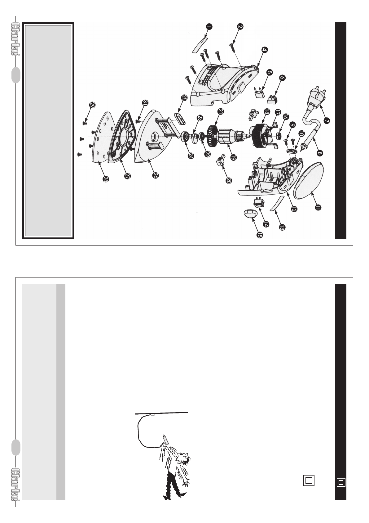
28 HTP510528 Screw 5
29 HTP510529 Screw 4
30 6462060 Accessory/Replenishment Pack 1
25 HTP510525 Extractor Duct 1
26 HTP510526 Vibration Plate 1
27 HTP510527 Base 1
IMPORTANT:
24 HTP510524 Bearing 1
Parts List
Item Part No Description Qty
01 HTP510501 Name Plate 1
02 HTP510502 Screw 6
04 HTP510504 Right Cover 1
05 HTP510505 Capacitor 1
06 HTP510506 Terminal Block 1
07 HTP510507 Power Cord Inc 13amp Plug 1
08 HTP510508 Cable Sheath 1
09 HTP510509 Screw 2
10 HTP510510 Cable Clamp 1
11 HTP510511 Upper Cover 1
12 HTP510512 Left Cover 1
13 HTP510513 Label 1
14 HTP510514 Switch 1
15 HTP510515 Protective Cover 1
16 HTP510516 Bearing 1
17 HTP510517 Inductor 2
18 HTP510518 Coil 1
19 HTP510519 Rotor 1
20 HTP510520 Brush Holder 2
21 HTP510521 Impeller 1
22 HTP510522 Bearing 1
23 HTP510523 Ecentric Cam 1
Page 5
SERVICE: [email protected]
PARTS: [email protected]
PARTS & SERVICE TEL: 020 8988 7400
or e-mail as follows:
Parts Diagram
-4--7-
Voltage Extension length Cable section
230v Up to 20m 2.5mm2230v From 20 to 50m 4mm
2
Consult a qualified technician.
IMPORTANT: If in any doubt, do not attempt any electrical repair yourself.
replacement must be approved to BS1362.
If a cable extension is needed, it is essential to comply with the following data.
4. Replacement fuse covers can be obtained from your local dealer or most electrical
5. The fuse in the plug must be replaced with one of the same rating (13 amps) and this
carrier, ensure that the correct replacement
is used (as indicated by marking or colour
code).
stockists.
2. Never use the plug without the fuse cover
3. Should you wish to replace a detachable fuse
the electric cable. There is a danger of electric
shock if it is subsequently inserted into a socket
outlet.
fitted.
IMPORTANT:
the electric cable (i.e. non- re-wireable) please note:
1. The plug must be thrown away if it is cut from
BLACK
If this appliance is fitted with a plug which is moulded on to
IMPORTANT:
IMPORTANT:
As the colours of the flexible cord of this appliance may not correspond with the coloured
markings identifying terminals in your plug proceed as follows:
• Connect BROWN coloured cord to plug terminal marked with a letter L or coloured
• Connect BLUE coloured cord to plug terminal marked with a letter N or coloured
RED
the following code:
13 Amp BS1363 plug, or a suitably fused isolator switch.
WARNING: This appliance is DOUBLE INSULATED
The wires in the mains lead are coloured in accordance with
Brown - Live
Blue - Neutral
Connect the mains lead to a standard 230V (50Hz) electrical supply through an approved
Electrical Connections
Page 6
This indicates worn brushes. This problem is quickly remedied but you should consult your
Check to ensure the fuse is sound and replace if necessary. If the fuse is sound or blows
repeatedly, consult your CLARKE dealer.
CLARKE dealer for parts and advice.
Sander does not operate when switched ON
do not apply excessive pressure.
Excessive sparking occurs
Sander is overheating
This indicates the machine is dirty. Clean the ventilation holes, and blow out with compressed
air or clean with a dry cloth.
Overloading the machine will also cause overheating. Do not use for heavy duty work, and
-5-
Check the power cable to ensure it is sound and free from cracks, bare wires etc. Avoid
using solvents when cleaning plastic parts, most plastics are susceptible to damage from
the various types of commercial solvents.
All bearings etc., in this tool are lubricated with a sufficient amount of high grade lubricant
for the tools lifetime under normal operating conditions, therefore no further lubrication is
required.
Trouble Shooting
Always inspect the tool before use, and ensure it is in top condition.
Ensure all air vents are clear, (use compressed air to clean the machine where possible).
Note: Do Not start the sander whilst it is in contact with the workpiece.
power supply cable entry.
3. Using The Sander.
Maintenance
2. Dust Extraction.
Dust extraction equipment (not supplied)
connecting a suitable hose to the outlet port at the rear of the machine just below the
a) Select pad to be used. (MUST be correct pads with velcro fitting ability).
b) Ensure sander is switched OFF and plug is removed from socket.
c) Line up holes in pad with those on machine pad. (this is necessary for dust
extraction), press pad firmly onto machine pad to secure it.
,
can be used with your sander, this is possible by
Holding the sander firmly, insert the plug into the mains socket and switch ON, turn the
sander on by operating the switch on the front of the tool.
Offer sander to workpiece and work slowly backwards and forwards across the area to be
sanded until finished. Remove sander from workpiece and switch OFF. Wait until machine
has stopped completely before putting it down.
1. Fitting Sanding Pad.
Operation
-6-
NOTES
 Loading...