

Page 1
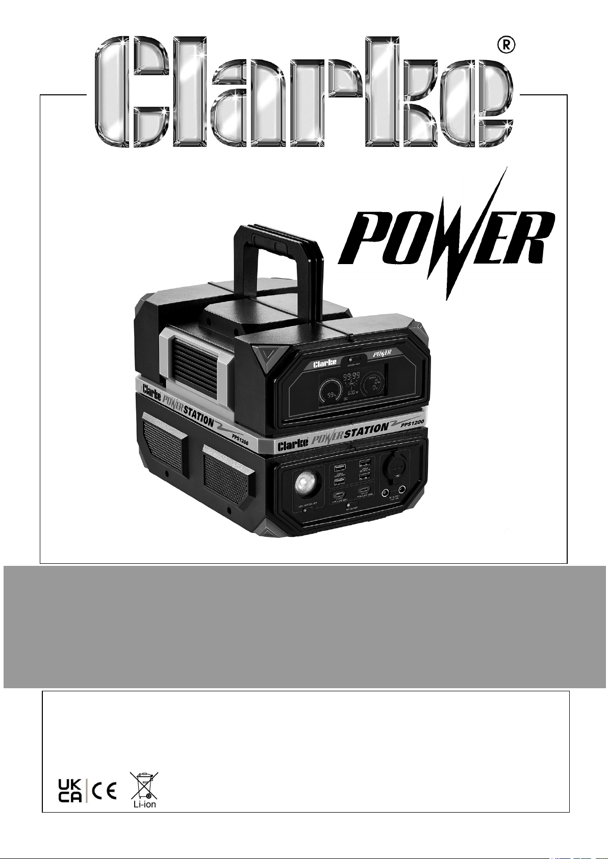
1200W PORTABLE POWER STATION
MODEL NO: PPS1200
PART NO: 8877145
OPERATING & MAINTENANCE
INSTRUCTIONS
ORIGINAL INSTRUCTIONS DL0625 Rev 2
Page 2
INTRODUCTION
Thank you for purchasing this CLARKE Portable Power Station. Before attempting to
use this product, please read this manual thoroughly and follow the instructions
carefully. In doing so you will ensure the safety of yourself and that of others around
you, and you can look forward to your purchase giving you long and satisfactory
service. Please keep these instructions in a safe place for future reference.
ENVIRONMENTAL RECYCLING POLICY
Through purchase of this product, the customer is taking on the obligation
to deal with the WEEE in accordance with the WEEE regulations in relation
to the treatment, recycling & recovery and environmentally sound disposal
of the WEEE.
In effect, this means that this product must not be disposed of with
general household waste but in accordance with the laws governing Waste Electrical
and Electronic Equipment (WEEE) at a recognised disposal facility.
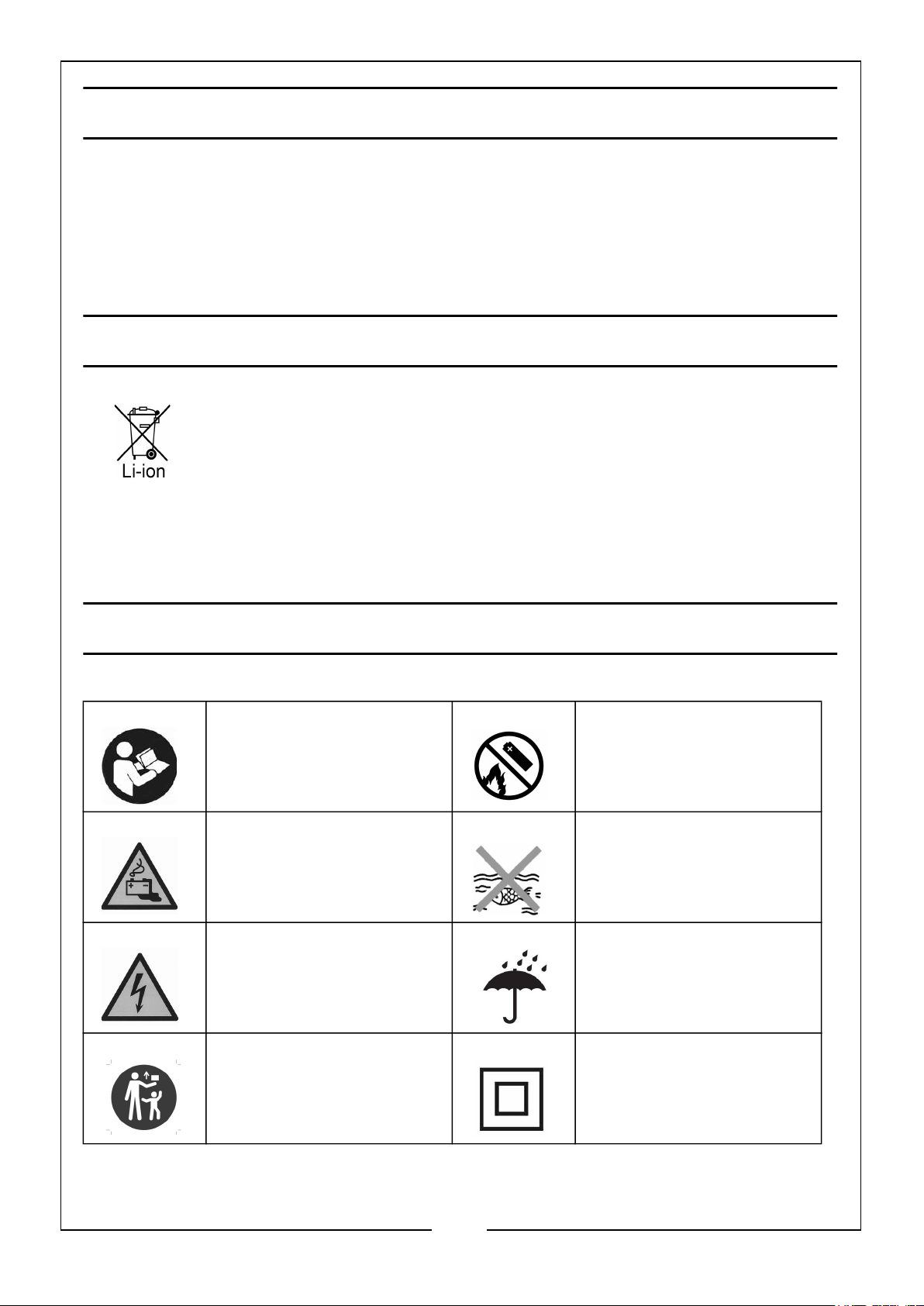
SYMBOLS SHOWN ON THIS PRODUCT
Read the instruction
manual
Warning: Battery
Charging
Warning: Risk of
electrical shock
Keep out of reach of
children
DO NOT incinerate
Harmful to aquatic life
Protect from rain/
water
Class II Product. (Only
use with Class II
products)
2
Parts & Service: 020 8988 7400 / E-mail: [email protected] or [email protected]
Page 3

GENERAL SAFETY
1. WARNING: This product is only suitable to be used with Insulation Protection
Class II products.
2. DO NOT use this power station near heat sources such as fire or stoves.
3. AVOID contact with any liquid. DO NOT immerse the power station in water or
get it wet. DO NOT use the power station in the rain or wet conditions.
4. DO NOT use the power station in environments with strong static electricity and
magnetic fields.
5. DO NOT disassemble the power station in any way or pierce the outer shell with
sharp objects.
6. DO NOT use any unofficial components or accessories. For replacement of any
part or accessory, contact your CLARKE Parts & Service department listed at the
bottom of this page.
7. When using the power station, strictly abide by the ambient temperature specified
in this manual. If the temperature is too high or too low, the product will not work
properly.
8. DO NOT place any heavy object on top of the power station.
9. During use, DO NOT forcibly block the fan operation or place the product in a
non-ventilated or dusty environment.
10. AVOID shock, dropping or severe vibration when using the power station. In case
of severe external shock, immediately turn off the power and stop using the
product until checked by an expert.
11. Place the power station on a flat surface to prevent damage from tipping over.
12. If the power station is seriously damaged in anyway, turn it off immediately, place
the power station in an open area away from flammable objects and people. If
need be, dispose of it in accordance with the WEEE regulations.
13. Keep the power station out of the reach of children and pets.
3
Parts & Service: 020 8988 7400 / E-mail: [email protected] or [email protected]
Page 4
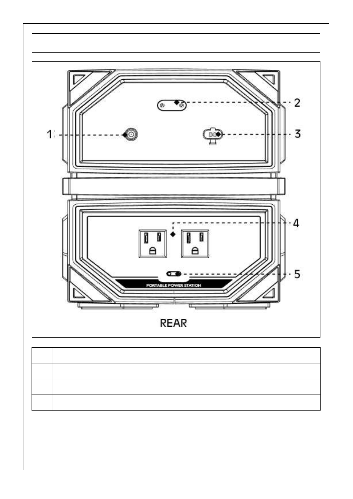
OVERVIEW - REAR
NO DESCRIPTION NO DESCRIPTION
1 DC Input Charging Port 4 2 x AC 230V Output Socket
2 Battery Rescue Charging Port 5 AC Output Socket ON/OFf Switch
3 DC Solar Panel Input Port
4
Parts & Service: 020 8988 7400 / E-mail: [email protected] or [email protected]
Page 5
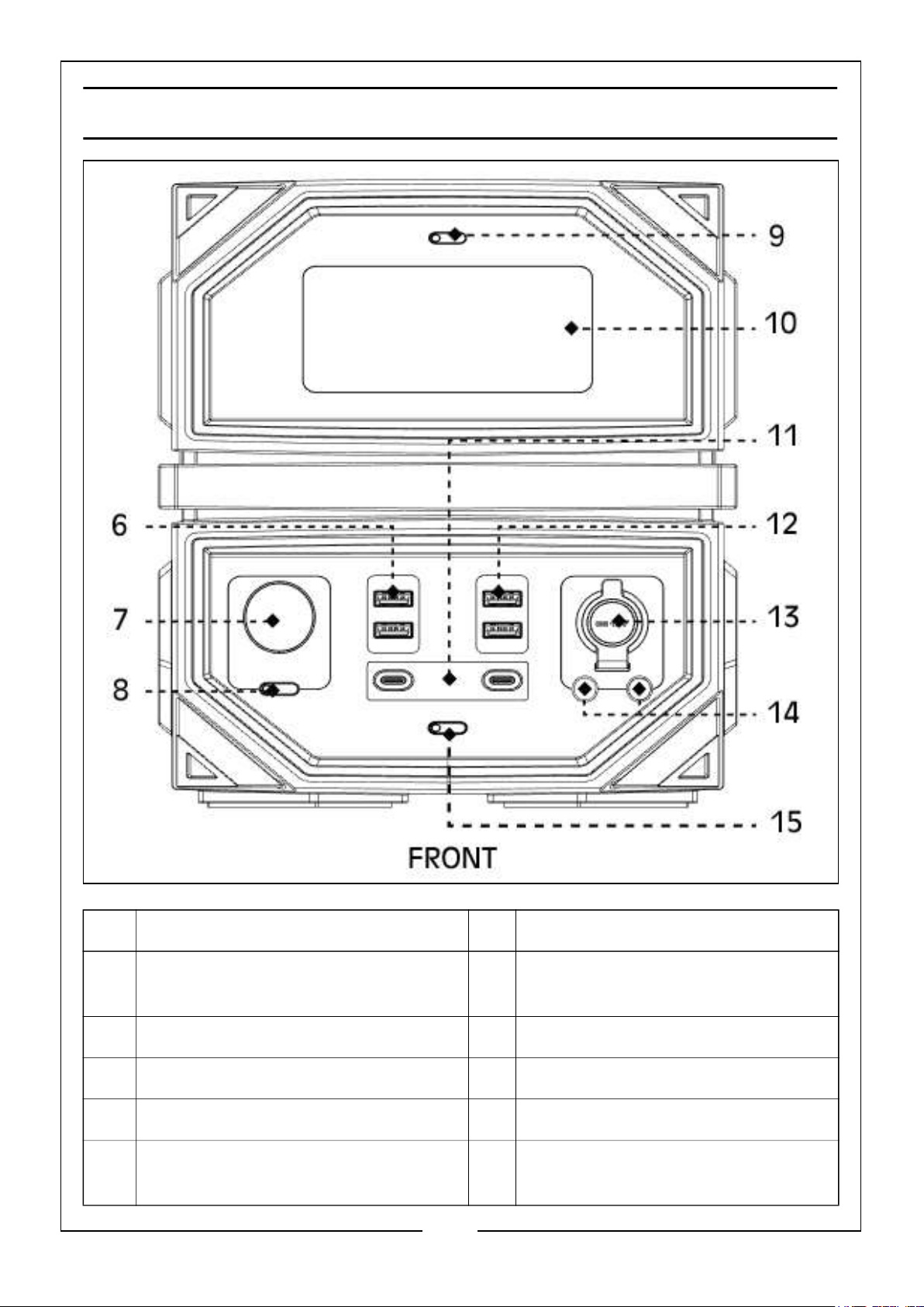
OVERVIEW - FRONT
NO DESCRIPTION NO DESCRIPTION
6 2 x USB-A (QC3.0, 18W) Socket 11 2 x DC USB Type C
(PD 60W & PD 100W) Socket
7 LED Light 12 2 x USB-A (DC 5V/3.1A) Socket
8 LED Light ON/OFF Switch 13 DC 12V Car Type Socket
9 LCD Screen ON/OFF Switch 14 2 x DC (6.5x1.4mm) Socket
10 LCD Screen 15 All USB & DC Output Sockets ON/
OFF Switch
5
Parts & Service: 020 8988 7400 / E-mail: [email protected] or [email protected]
Page 6
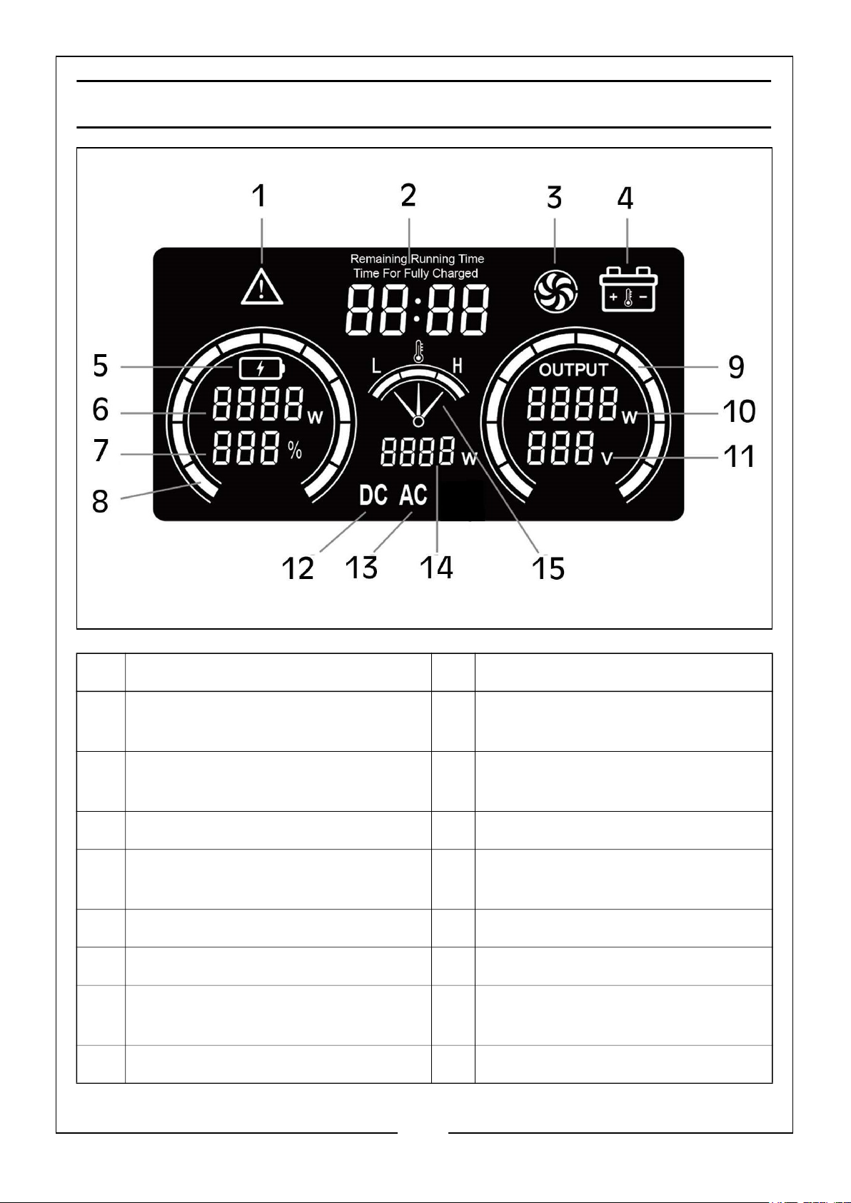
LCD DISPLAY OVERVIEW
NO DESCRIPTION NO DESCRIPTION
1 Power Station Failure - Overheat,
Overload, Short Circuit
2 Battery Run Time/Time to Full
Charge Battery
3 Fan 11 AC Output Voltage
4 Battery High and Low
Temperature Fault
5 Charge Icon 13 AC Output
6 Charge Power 14 Inverter Power
7 Battery Power 15 Temperature Fault -
8 Battery Level Display
9 Load Status Display
10 Load Power
12 DC Output
Low/Normal/High
6
Parts & Service: 020 8988 7400 / E-mail: [email protected] or [email protected]
Page 7
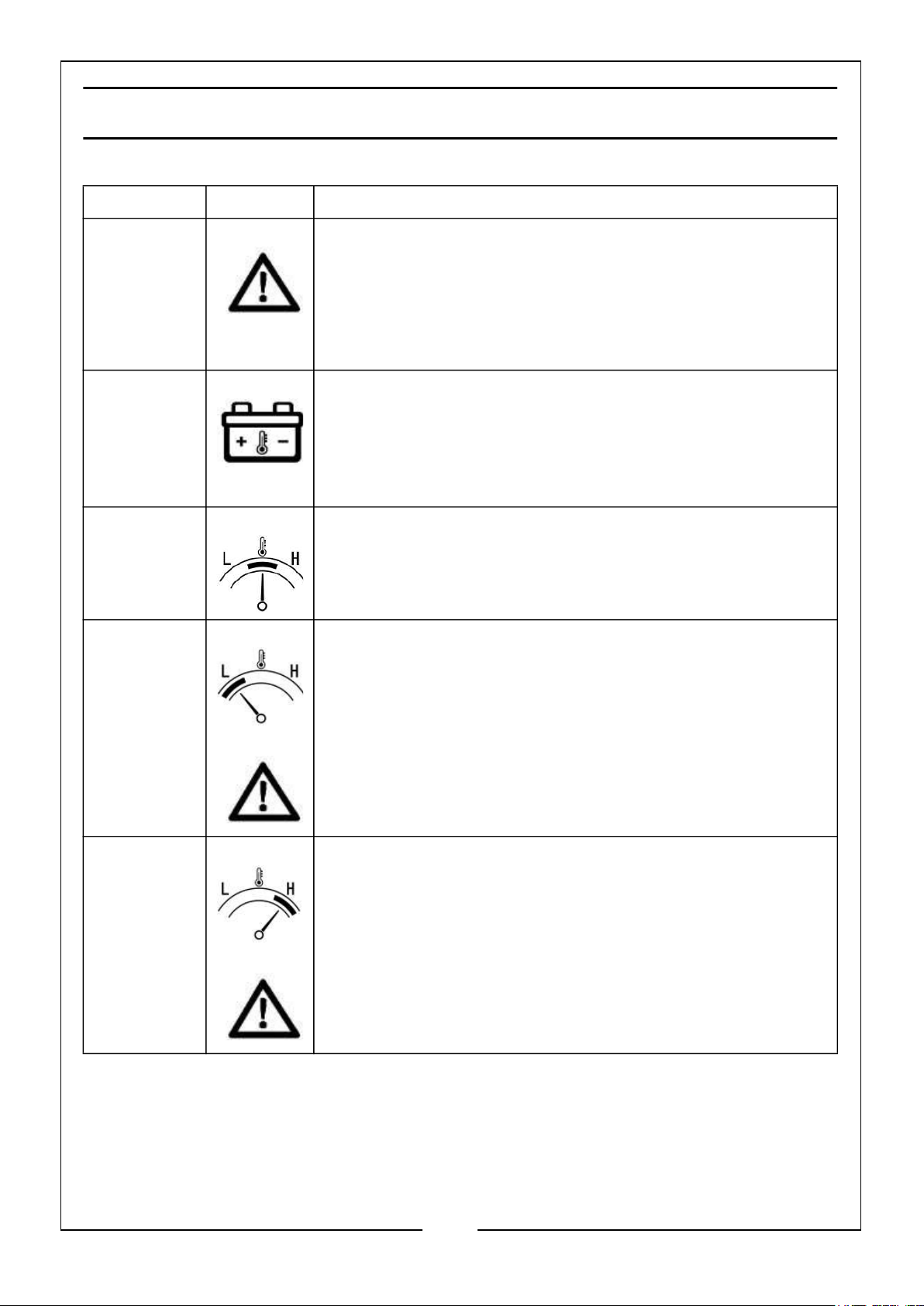
LCD DISPLAY DESCRIPTIONS
Icon No. Icon Fault Description and Handling Methods
1 Inverter Fault Icon. Displayed when fault occurs
(including: short circuit, overload, under voltage, over
voltage, over temperature etc.) When under voltage
occurs, there will be an alarm (10 seconds), the AC icon
(13) in the display will flash and the green light of the AC
switch will flash.
4 Battery Failure Icon.
15 Normal Temperature. The pointer will be in the middle.
1 & 15 Low Temperature Fault. Icons 1 & 15 will appear
simultaneously. The pointer will be to the left (Low).
1 & 15 High Temperature Fault. Icons 1 & 15 will appear
simultaneously. The pointer will be to the right (High).
7
Parts & Service: 020 8988 7400 / E-mail: [email protected] or [email protected]
Page 8
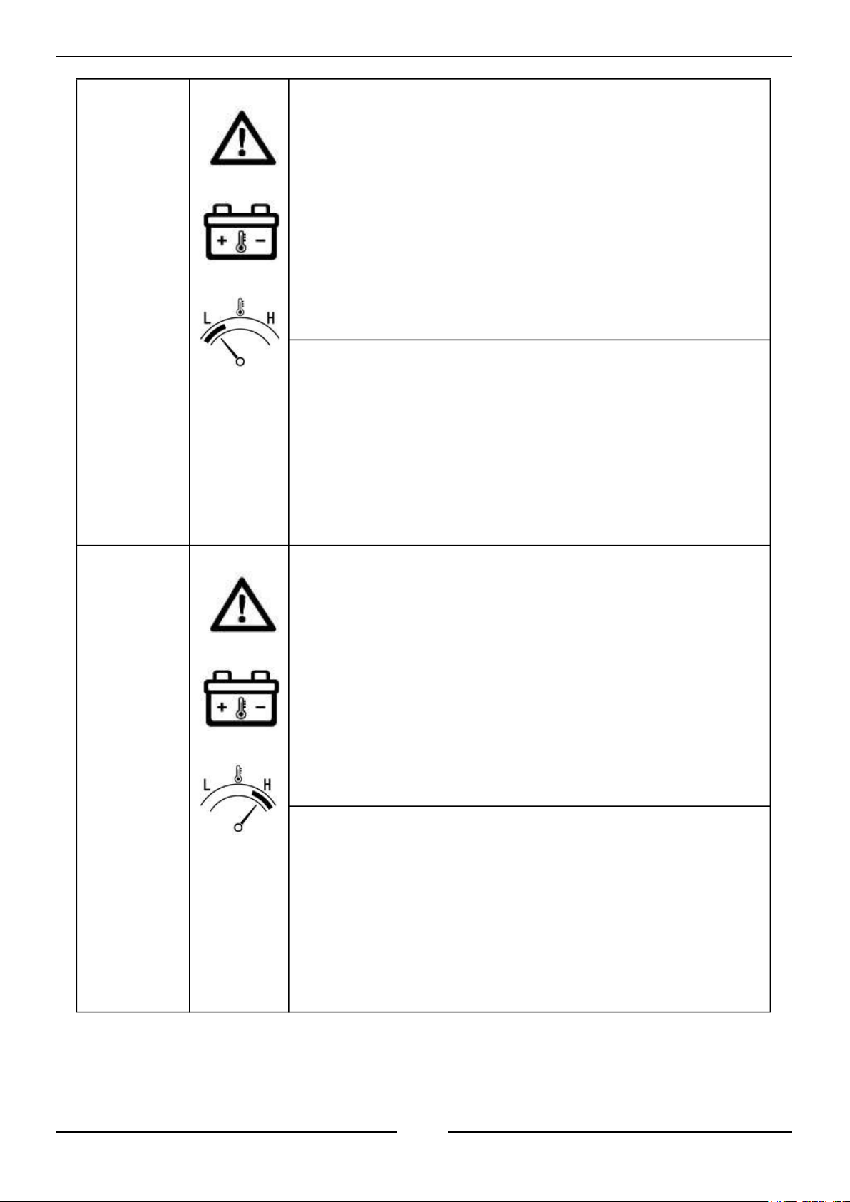
1, 4 & 15
(Low)
Battery Discharge Failure in Low Temperature
Environment.
• When the battery is protected against low
temperature level I and the icons 1, 4 & 15
(Low) are displayed at the same time.
• When the battery is protected against low
temperature level II, LCD display is off, and
the red light of the AC switch flashes.
• Recovery temperature after discharge low
temperature protection: -10°C +/- 3°C
Battery Charging Failure in Low Temperature
Environment.
• When the battery is under low temperature
protection, the icons 1, 4 & 15 (Low) are
displayed at the same time and icon 15 (Low)
is flashing.
1, 4 & 15
(High)
• Recovery temperature after charging low
temperature protection: 0°C +/- 3°C
Battery Discharge Failure in High Temperature
Environment.
• When the battery is protected against high
temperature level I, and the icons 1, 4 & 15
(Low) are displayed at the same time.
• When the battery is protected against high
temperature level II, LCD display is off, and
the red light of the AC switch flashes.
• After the battery cools down it resumes
normal operation.
Battery Charging Failure in Low Temperature
Environment.
• When the battery is under low temperature
protection, the icons 1, 4 & 15 (High) are
displayed at the same time, and icon 15
(High) is flashing.
• After the battery cools down it resumes
normal operation.
8
Parts & Service: 020 8988 7400 / E-mail: [email protected] or [email protected]
Page 9
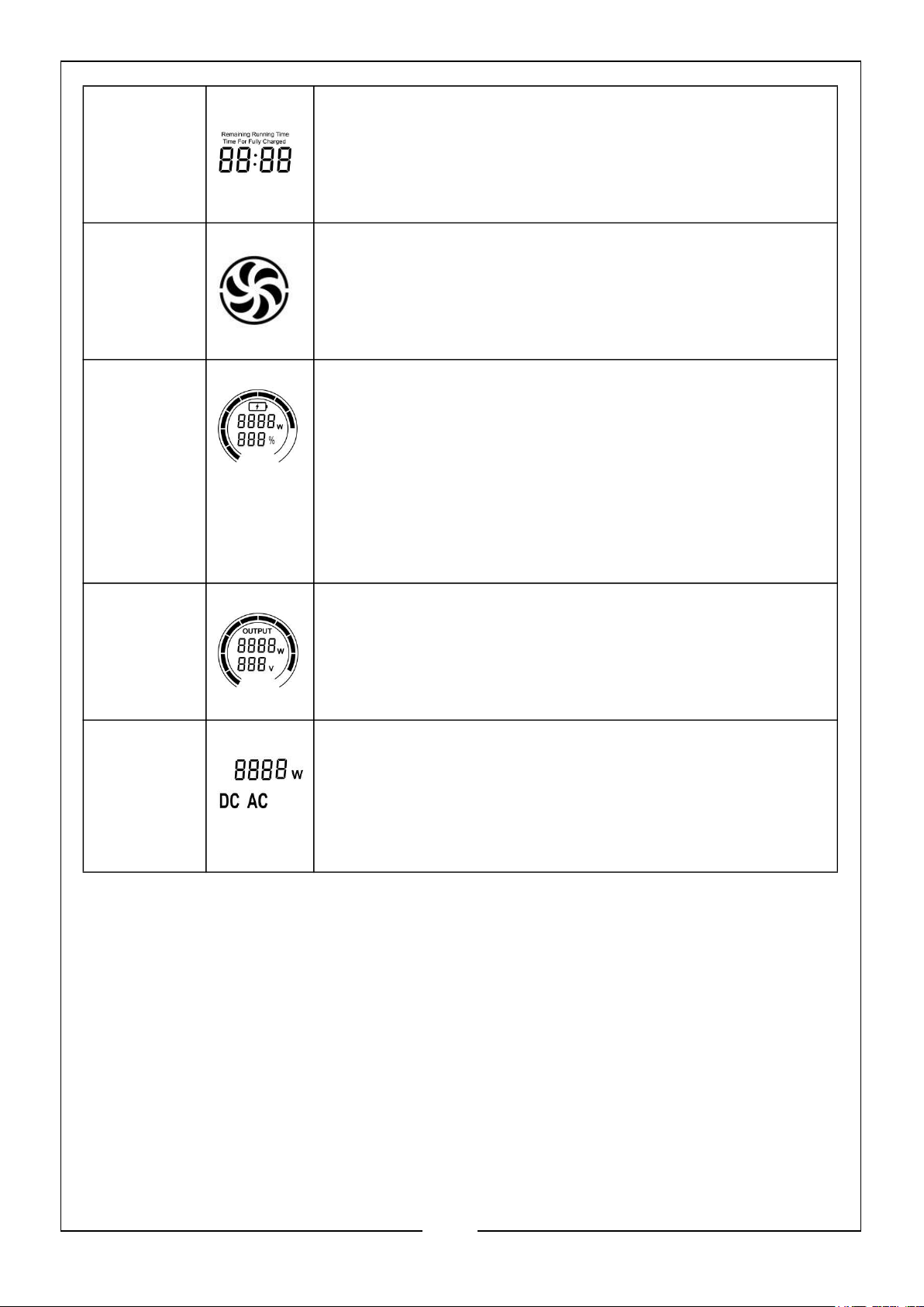
2 Time for Fully Charged. Battery running time.
3 Fan Icon. Appears when the fan is working.
5, 6, 7 & 8 Icon 5: Battery Charging Icon. Appears when
charging
Icon 6: Battery Charging Power. Appears when
charging.
Icon 7: Battery Percentage.
Icon 8: Battery Power Display. When charging, the bar
corresponding to the battery will flash; if the battery shows
0%, the Icon 8 will flash. Each section
corresponds to approximately 10%.
9, 10 & 11 Icon 9: Display of Total Load Power. Each section
corresponds to approximately 10%.
Icon 10: Total Load Power. Sum of all loads, including
AC, USB-A, Type-C, DC & LED Light.
Icon 11: AC Output Voltage.
12, 13 & 14 Icon 12: DC Icon. Appears when the DC switch is turned
ON, flashes when overloaded or short circuited.
Icon 13: AC Icon. Appears when the AC swi9tch is turned
ON, and flashes any fault occurred including short circuit,
overload, under voltage, over voltage & over temperature.
Icon 14: Power Station Specifications. Inverter power
9
Parts & Service: 020 8988 7400 / E-mail: [email protected] or [email protected]
Page 10
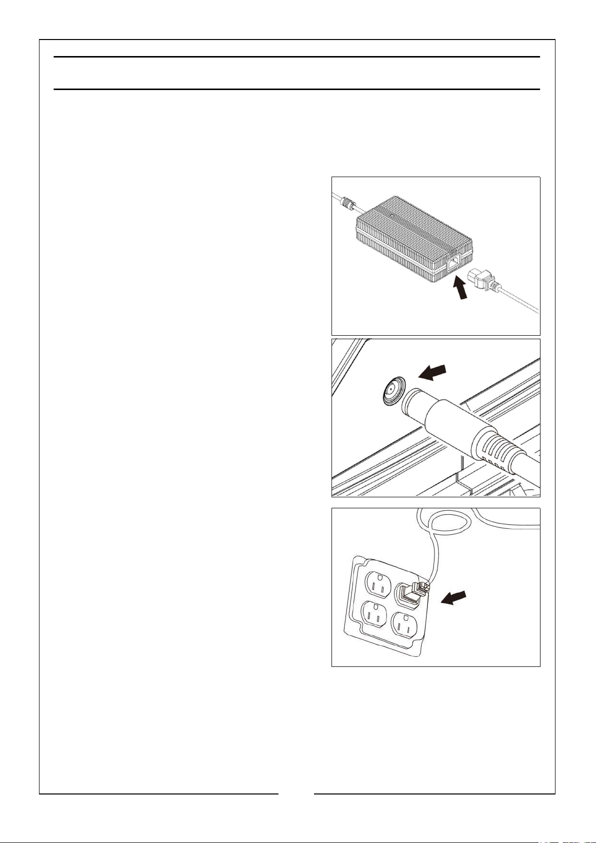
CHARGING THE DEVICE
The battery power of the power station will be consumed during use. You can choose
the following methods to charge the power station.
CHARGING BY ADAPTER
1. Connect the AC plug cable to the adapter.
2. Insert the DC plug of the adapter into the
charging port on the rear of the power
station.
3. Insert the AC plug into a mains outlet
socket.
NOTE: Always operate this procedure in the
above order. when fully charged or
need to stop charging, you must first
unplug the AC plug from the mains
outlet socket, then pull out the DC
plug, and finally store the adapter
and plug cord.
10
Parts & Service: 020 8988 7400 / E-mail: [email protected] or [email protected]
Page 11
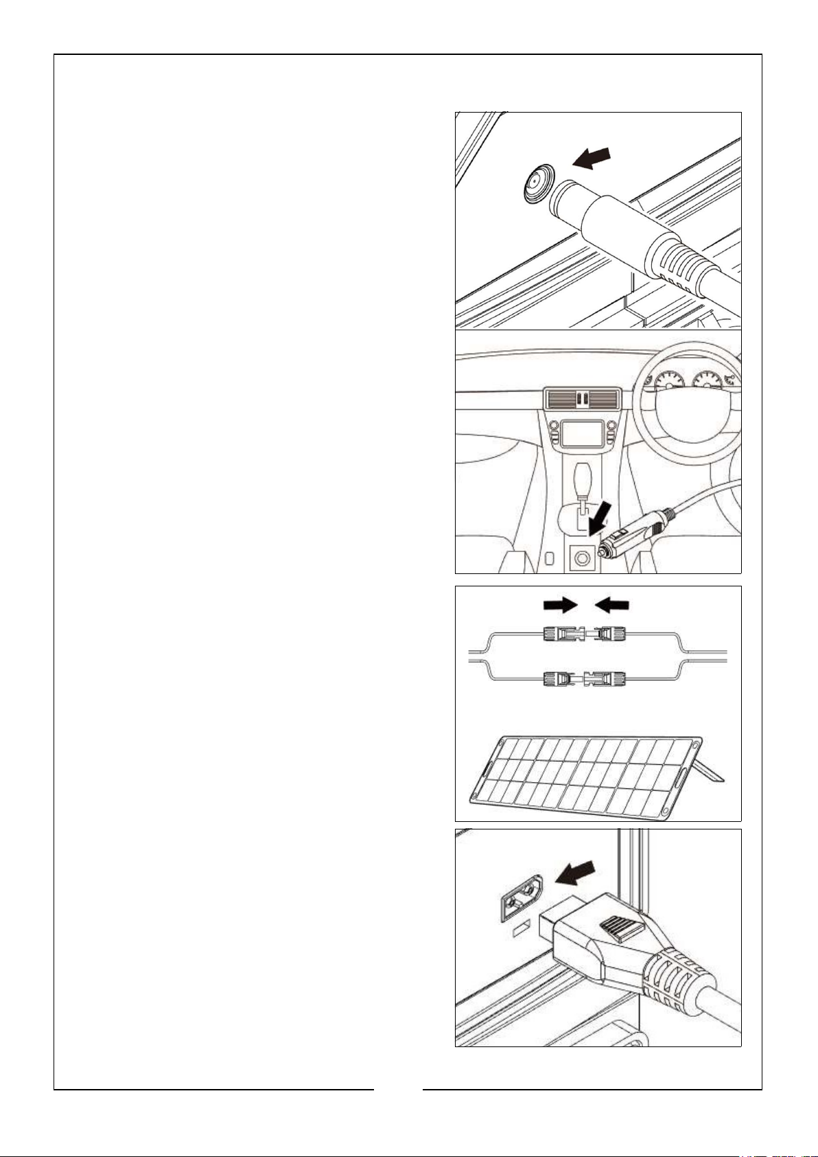
CHARGING BY 12V DC OUTLET
1. Insert the DC plug of the adapter into the
charging port on the rear of the device.
2. Insert the 12V DC plug into the 12V DC
outlet socket in a vehicle or generator.
NOTE: Always operate this procedure in the
above order. when fully charged or
need to stop charging, you must first
unplug the 12V DC plug from the
vehicle or generator socket, then pull
out the DC plug, and finally store the
adapter and plug cable.
CHARGING BY SOLAR PANEL
1. Connect the solar panel charging cable to
the solar panel.
NOTE: CLARKE solar panels are sold
separately, as follows:
• SFP1 (6487078); Foldable Solar Panel
100W
• SFP2 (6487079); Foldable Solar Panel
200W
2. Insert the DC plug into the charging port
of the power station.
11
Parts & Service: 020 8988 7400 / E-mail: [email protected] or [email protected]
Page 12
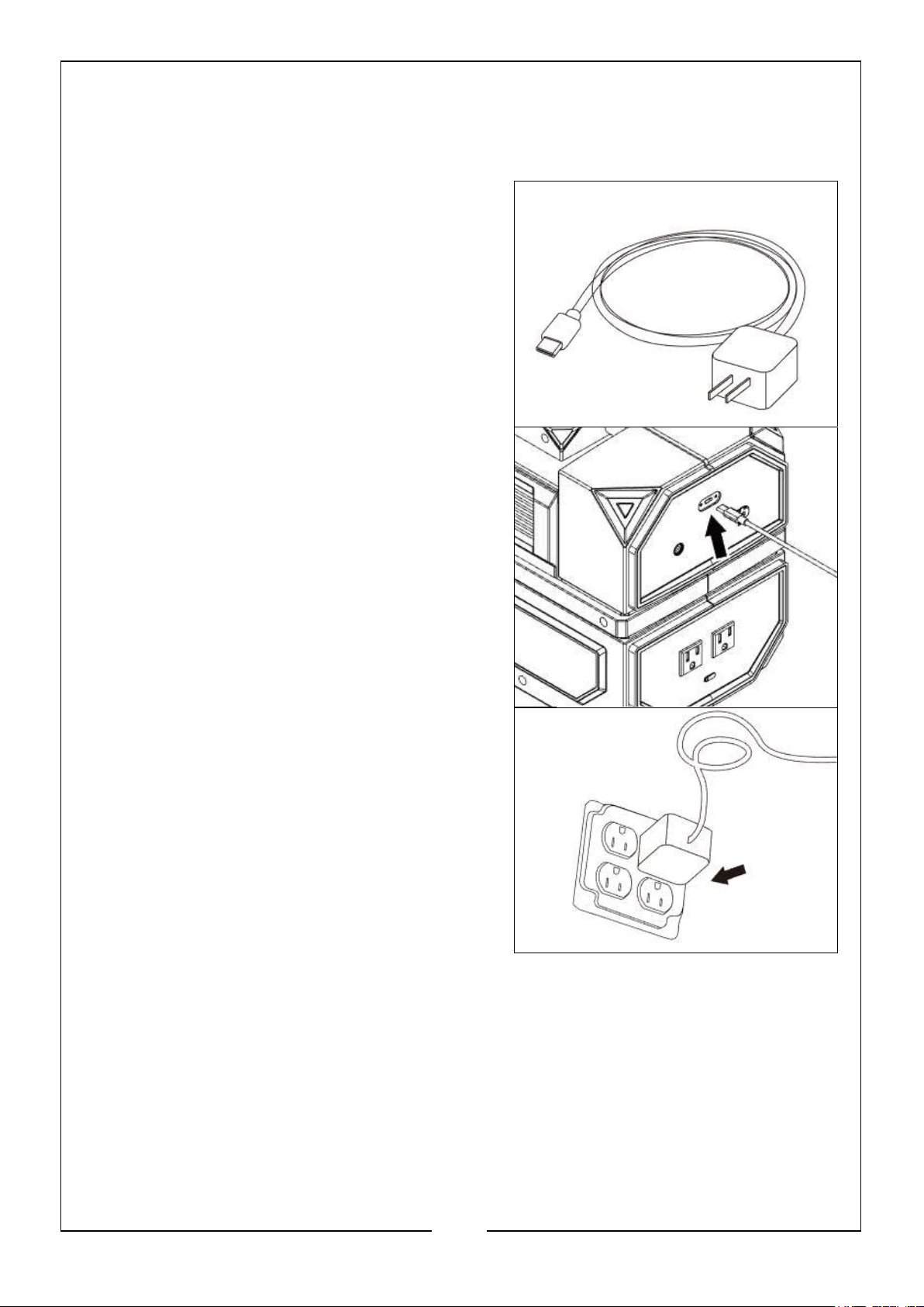
CHARGING BY THE BATTERY RESCUE PORT
This method should only be used if the battery is seriously low and cannot be charged
by normal methods.
1. You will need a USB Type C charging cable
and plug (not supplied).
2. Unscrew the cover of the battery rescue
port which is located on the rear of the
power station.
3. Insert the USB Type C charging cable into
the battery rescue port.
4. Plug the USB Type C cable and plug into a
mains power supply.
NOTE: This method takes a long time
(approx. 10 Hours). Once the LCD
display lights up, change to another
charging method.
12
Parts & Service: 020 8988 7400 / E-mail: [email protected] or [email protected]
Page 13
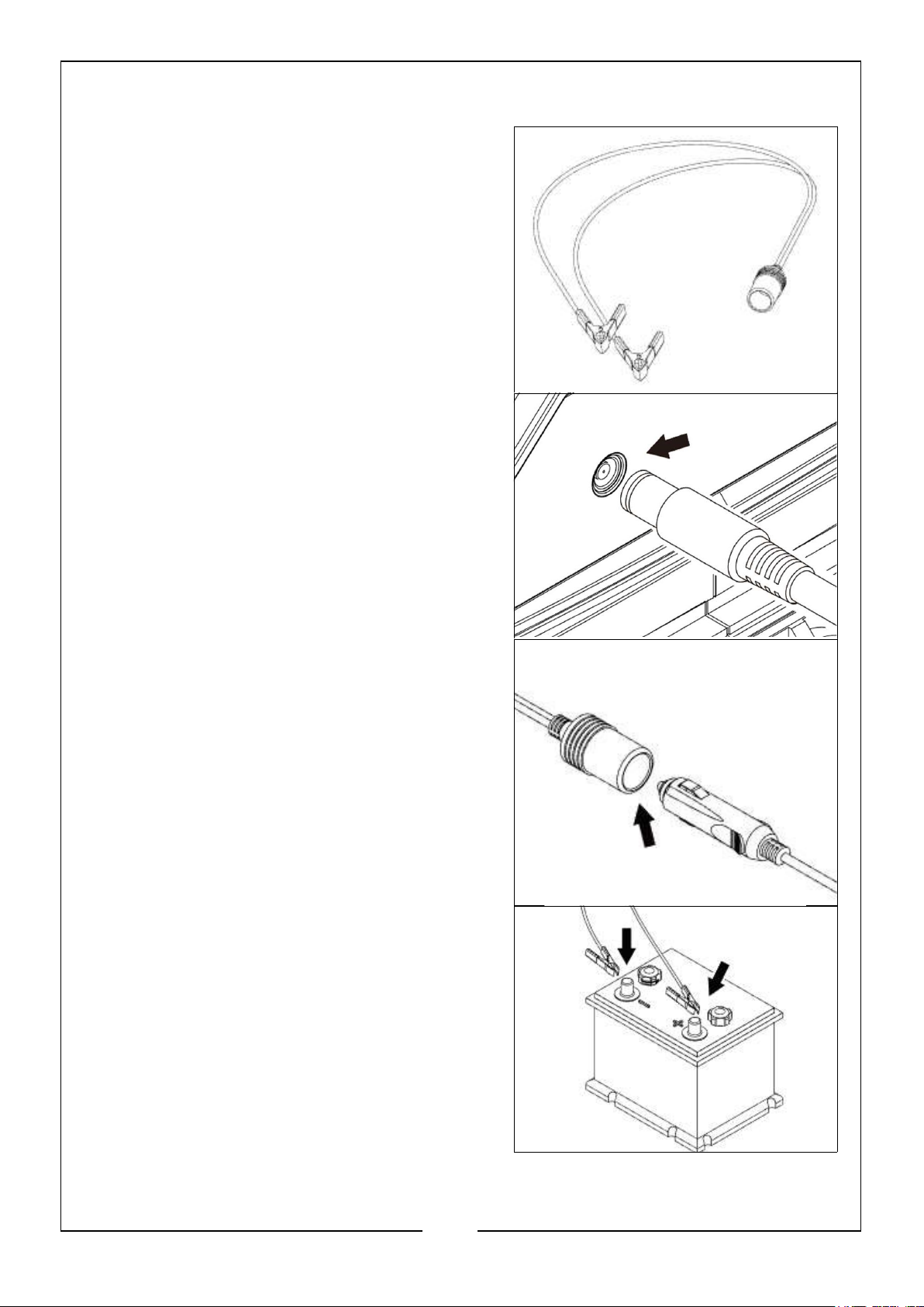
CHARGING BY BATTERY
1. If charging through a separate battery, the
user needs a battery clip adapter cable, as
shown (not supplied).
2. Insert the DC plug of the adapter into the
charging port on the rear of the device.
3. Insert the 12V DC adapter into the battery
clip adapter, as shown.
4. Clamp the battery clip adapter onto the
battery, making sure the red (+) clamp is
attached to the positive battery terminal
and the black (-) clamp is attached to the
negative battery terminal.
NOTE: Make sure the battery holds enough
power to charge the power station.
13
Parts & Service: 020 8988 7400 / E-mail: [email protected] or [email protected]
Page 14
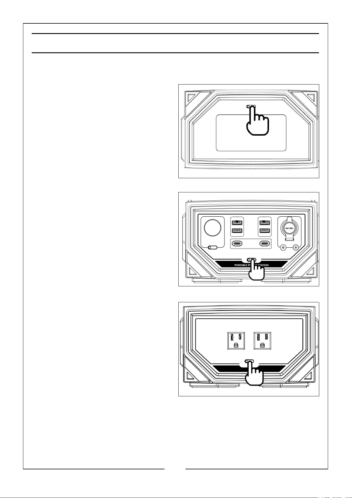
OPERATION
LCD DISPLAY ON/OFF
Short press the LCD switch to turn ON/
OFF the LCD screen (ON: the green
indicator light on the button will be on,
OFF: the indicator light will be off).
Turn on any switch of DC, AC and the
light, the LCD screen will also light up.
After the LCD screen is turned on, it will
automatically turn off if there is no
operation for 5 minutes.
DC OUTPUT ON/OFF
Short press the DC switch to turn ON/
OFF all DC output sockets (ON: the
green indicator light on the button will be
on, OFF: the indicator light will be off),
these include all USB-A, Type-C & 12V
DC sockets.
Turn off the DC switch when not in use
to save power.
AC OUTPUT ON/OFF
Short press the AC switch to turn ON/
OFF the AC output socket (ON: the green
indicator light on the button will be on,
OFF: the indicator light will be off).
Turn off the AC switch when not in use
to save power.
14
Parts & Service: 020 8988 7400 / E-mail: [email protected] or [email protected]
Page 15
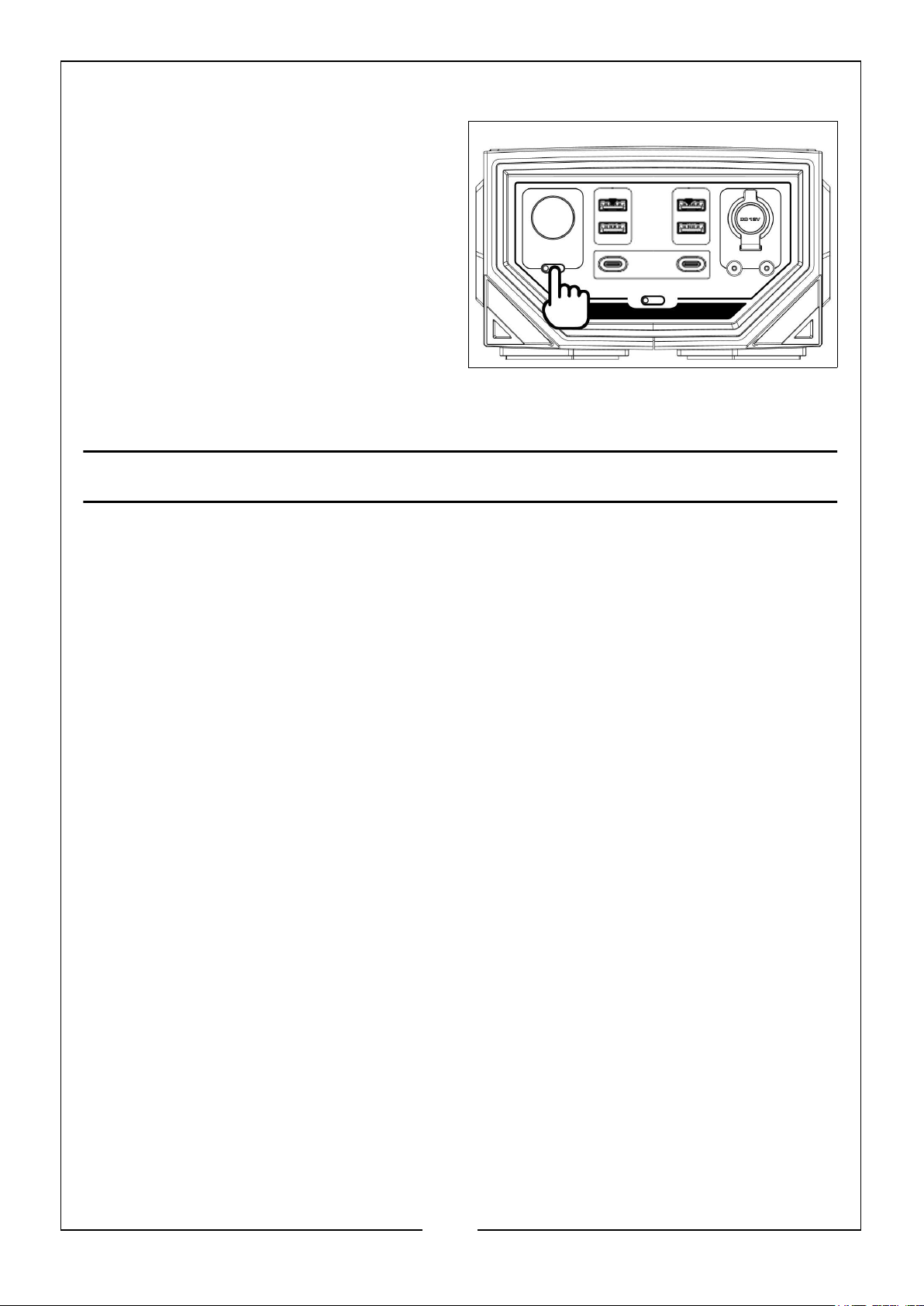
LED LIGHT
Short press the LED switch for the 3
different settings of the light as follows:
• 1 Press: Low Light
• 2 Presses: High Light
• 3 Presses: Flashing SOS mode
• 4 Presses: Off
NOTE: After the light has been on for
over 1 minute in any setting,
the light will turn off when the
switch is next pressed.
STORAGE & MAINTENANCE
1. Use and store the power station at an ambient temperature of 10°C to 30°C, away
from water, heat and other metal objects.
2. For safety reasons, DO NOT store the product in an ambient temperature above
45°C or below -10°C for extended periods of time.
3. For long term storage, discharge the battery to approximately 30% and recharge
to 30% every three months.
4. If the remaining power is less than 1% after you have finished using the power
station, recharge to 30%. If the power station is left idle for an extended period of
time with a critically low battery, it may damage the cells and shorten the life of
the product.
5. If the power station has been idle for a long period of time, the battery power is
seriously insufficient and cannot be charged normally. In this case, charge through
the battery rescue charging port until the LCD screen lights up, then it can be
charged in a normal way.
NOTE: The maximum charging current for the Battery Rescue Charging Port is
5V DC / 2A.
15
Parts & Service: 020 8988 7400 / E-mail: [email protected] or [email protected]
Page 16
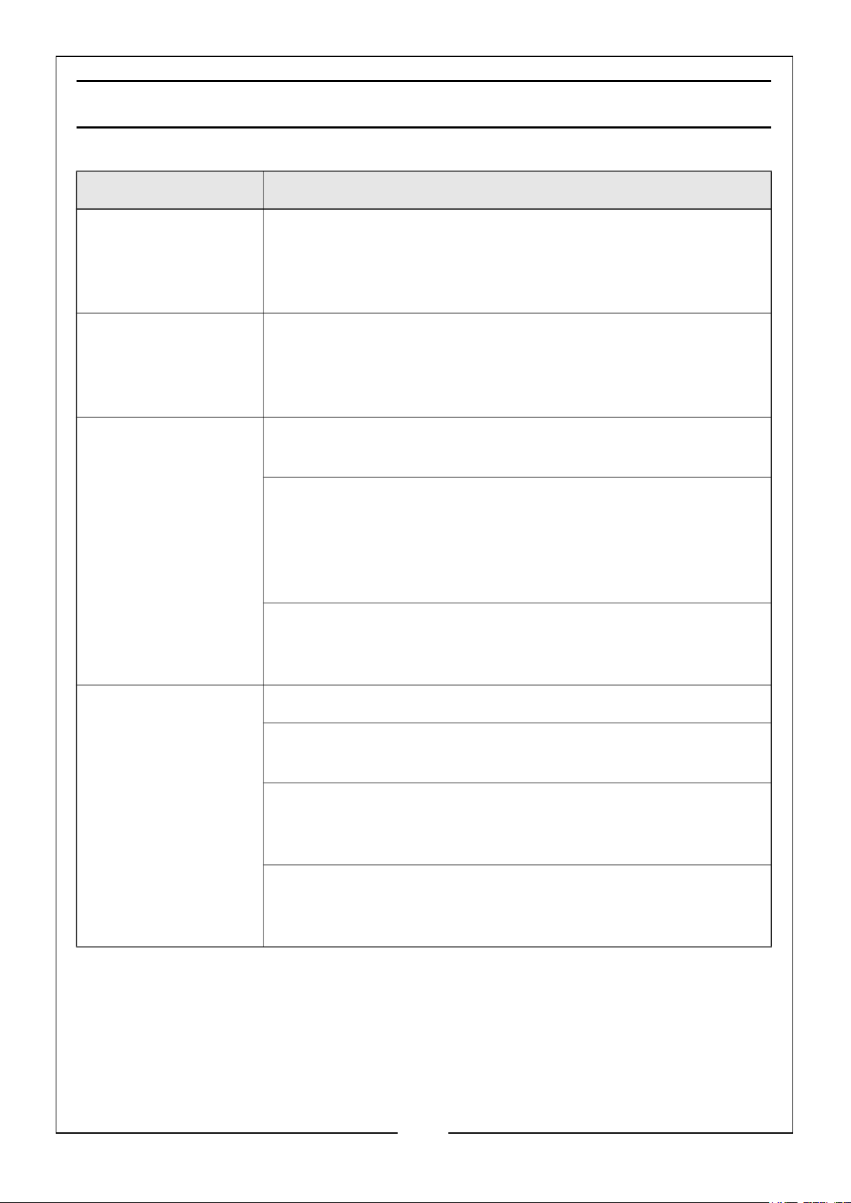
TROUBLESHOOTING
FAULT SOLUTION
Battery high
temperature
protection
Battery low
temperature
protection
DC can not charge
(12V DC & Solar
Panel)
Put the power station in a cool and ventilated place so it can
be restored after the temperature is lowered. NOTE: DO NOT
directly cool the power station by freezing, as this may
damage it.
Put the device in a warm environment so it can be restored
after the temperature rises. NOTE: DO NOT put the power
station in an oven, dryer or directly heat the device by other
means, as this may damage it.
Check if the charging voltage meets the device requirements:
DC charging requirements: 11 - 30V DC
Check if the indicator light of the power adapter is on, if not
check:
1. If the adapter is correctly connected.
2. Whether the AC socket and supply is working normally.
Battery high or low temperature protection has activated. See
LCD Display Descriptions or Storage & Maintenance for more
information.
No AC output Check whether the AC switch is on (green light showing)
Check whether the loaded device is connected to the AC
output correctly.
The equipment is overloaded or short-circuit protected. After
reducing the load or eliminating the fault, it can be restored
after restarting.
Battery under voltage protection. The power station needs to
be charged before use; AC switch should be turned off and the
turned back on.
16
Parts & Service: 020 8988 7400 / E-mail: [email protected] or [email protected]
Page 17
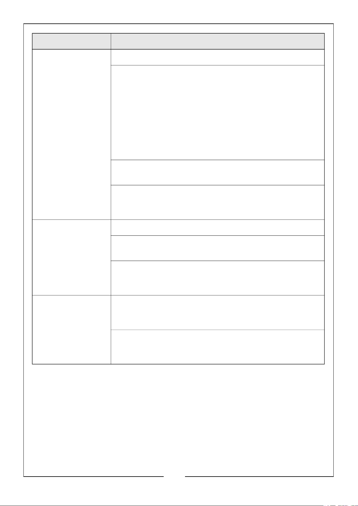
FAULT SOLUTION
No output from 12V
DC, DC ports, USB &
Type C connection
ports
LED light does not
light up
Check whether the DC switch is on (green light showing).
Check whether the green indicator light on the switch is
flashing, if it is flashing it may be:
1. Overload Recovery: reduce the load to within the rated
range.
2. DC Short Circuit Recovery: Check the load equipment
and eliminate the short circuit.
3. Module Over Temperature Recovery: Suspend use and
resume after cooling.
Battery under voltage protection. Needs to be charged before
use.
Battery high or low temperature protection has activated. See
LCD Display Descriptions or Storage & Maintenance for more
information.
Check whether the Light switch is on (green light showing).
Battery under voltage protection. Needs to be charged before
use.
Battery high or low temperature protection has activated. See
LCD Display Descriptions or Storage & Maintenance for more
information.
LCD Display, no
reaction
Battery high or low temperature protection has activated. See
LCD Display Descriptions or Storage & Maintenance for more
information.
The battery power is seriously low, charge it through the
battery rescue port until screen is lit, then fully charge it in a
usual way.
If these remedies are unsuccessful, consult your CLARKE dealer.
17
Parts & Service: 020 8988 7400 / E-mail: [email protected] or [email protected]
Page 18
SPECIFICATIONS
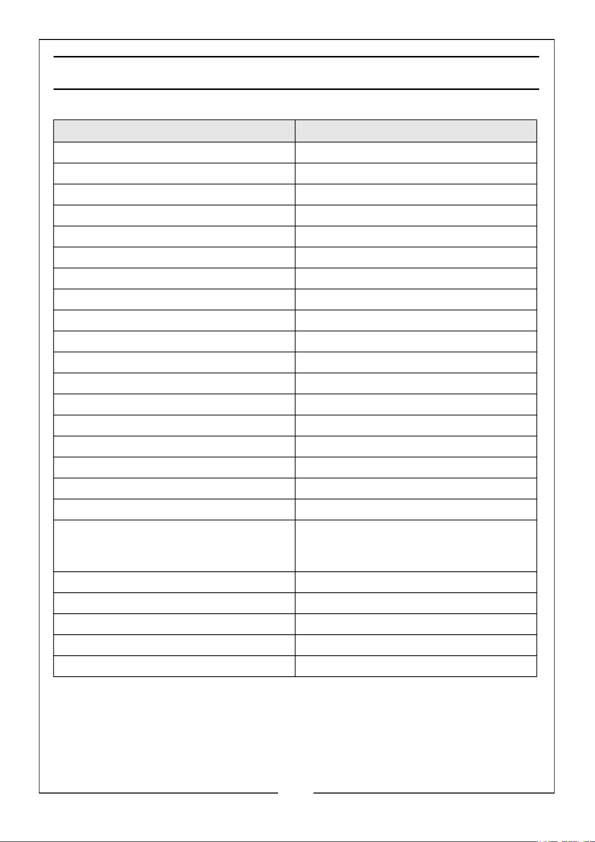
Item Specification
Model PPS1200
Part Number 8877145
Weight 6.3kg
Size (L x W x H) 290 x 198 x 207mm
Battery Charging Time (from Flat) 4 Hours
Battery Life (Running Full Power) Approx. 45 Minutes
Battery Cycles/Lifetime 500 Cycles to 80%
Operating Temperature 5 - 25°C
Max./Peak Output Wattage @ 230V 1200W
Continuous Output Wattage @ 230V 600W
Insulation Protection Class Class II
Input Charging Voltages 11 - 30V
AC Outlet Output Current (230V ~ 50Hz) 2.6A Measured
AC Power Output Voltage 230V - 50Hz
AC Power Supply Types 2 x Single BS1363 Socket
DC Outlet Output Current (5V) 3.0A-3.1A - PD 60W-100W
DC Outlet Output Current (12V) 10A Max.
DC Power Output Voltages 12V, 5V & 5V/9V/12V/15V/20V DC
DC Power Supply Types 1 x 12V Aux, 1 x 12V DC, 4 x USB-A (2 x
3.0A/18W shared & 2 x 3.1A shared) & 2
x Type-C (1 x 60W & 1 x 100W)
Battery Pack Electric Charge Value 20Ah
Battery Pack Watt Hours 504Wh
AC Charging Lead Fuse Rating 3A
Working Light LED, 3.5V, 2W
Ingress Protection Rating (IP) IPX0
Please note that the details and specifications contained herein, are correct at the
time of going to print. However, CLARKE International reserve the right to change
specifications at any time without prior notice.
18
Parts & Service: 020 8988 7400 / E-mail: [email protected] or [email protected]
Page 19
DECLARATIONS OF CONFORMITY
19
Parts & Service: 020 8988 7400 / E-mail: [email protected] or [email protected]
Page 20

 Loading...