

Page 1
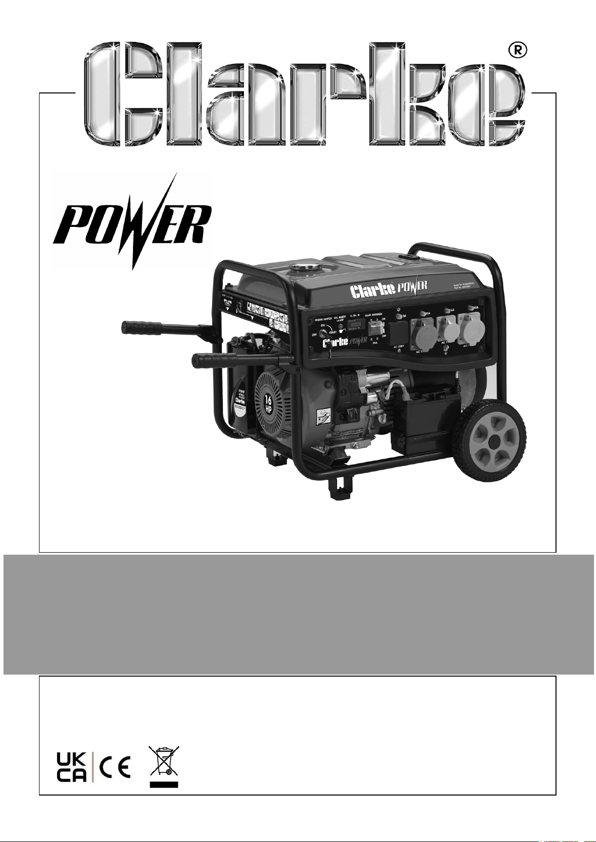
8.5KVA PETROL GENERATOR
MODEL NO: PG9500ADVES
PART NO: 8857860
OPERATION & MAINTENANCE
INSTRUCTIONS
DL1225
Page 2
INTRODUCTION
Thank you for purchasing this CLARKE Generator.
Before attempting to operate the machine, it is essential that you read this manual
thoroughly and carefully follow all instructions given. In doing so you will ensure the
safety of yourself and that of others around you, and you can also look forward to the
product giving you long and satisfactory service.
Ensure the generator and its components suffered no damage during transit and that
all components are present. Should any loss or damage be apparent, please contact
your CLARKE dealer immediately.
GUARANTEE
This CLARKE product is guaranteed against faulty manufacture for a period of 12
months from the date of purchase. Please keep your receipt as proof of purchase.
This guarantee is invalid if the product is found to have been abused or tampered
with in any way, or not used for the purpose for which it was intended.
Faulty goods should be returned to their place of purchase, no product can be
returned to us without prior permission.
This guarantee does not effect your statutory rights.
ENVIRONMENTAL RECYCLING POLICY
Through purchase of this product, the customer is taking on the obligation
to deal with the WEEE in accordance with the WEEE regulations in relation
to the treatment, recycling & recovery and environmentally sound disposal
of the WEEE.
In effect, this means that this product must not be disposed of with general
household waste. It must be disposed of according to the laws governing Waste
Electrical and Electronic Equipment (WEEE) at a recognised disposal facility.
If disposing of this product or any damaged components, do not dispose of with
general waste. This product contains valuable raw materials. Metal products should
be taken to your local civic amenity site for recycling of metal products.
2
Parts & Service: 020 8988 7400 / E-mail: [email protected] or [email protected]
Page 3
SPECIFICATIONS
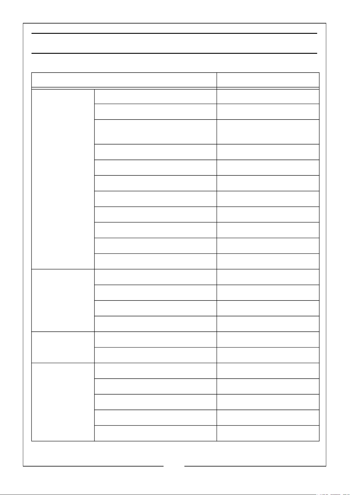
CLARKE part no 8857860 PG9500ADVES
Engine Engine Model SC460
Engine Power 16HP - 10.5kW
Fuel Type E10 Unleaded Petrol
(87 Octane Rate)
Displacement (cc) 459
Starting system Electric & Hand Recoil
Fuel tank capacity (Litre) 20 L (Safe Capacity)
Fuel consumption 3.3 L/Hr
Maximum run time @75% Load 6 hours 30 mins
Engine oil type SAE10W-30
Engine oil capacity (L) 1.1L
Battery Type 12V,18Ah, SLA
Generator Rated Frequency (Hz) 50
AC Output Voltage (V) 230 & 110
Rated Power (W) 8000
Max. Rated Power (W) 8500
Dimensions L x W x H (mm) 730 x 660 x 630
Unpacked Weight (kg) 100
Environmental IP Rating (Generator/Sockets) IP23M/IP44
Sound pressure level 74 dB
Sound power level 94 dB
Guaranteed sound power level 97 dB
Uncertainty factor 2.8 dB
3
Parts & Service: 020 8988 7400 / E-mail: [email protected] or [email protected]
Page 4
GENERAL SAFETY RULES & SYMBOLS
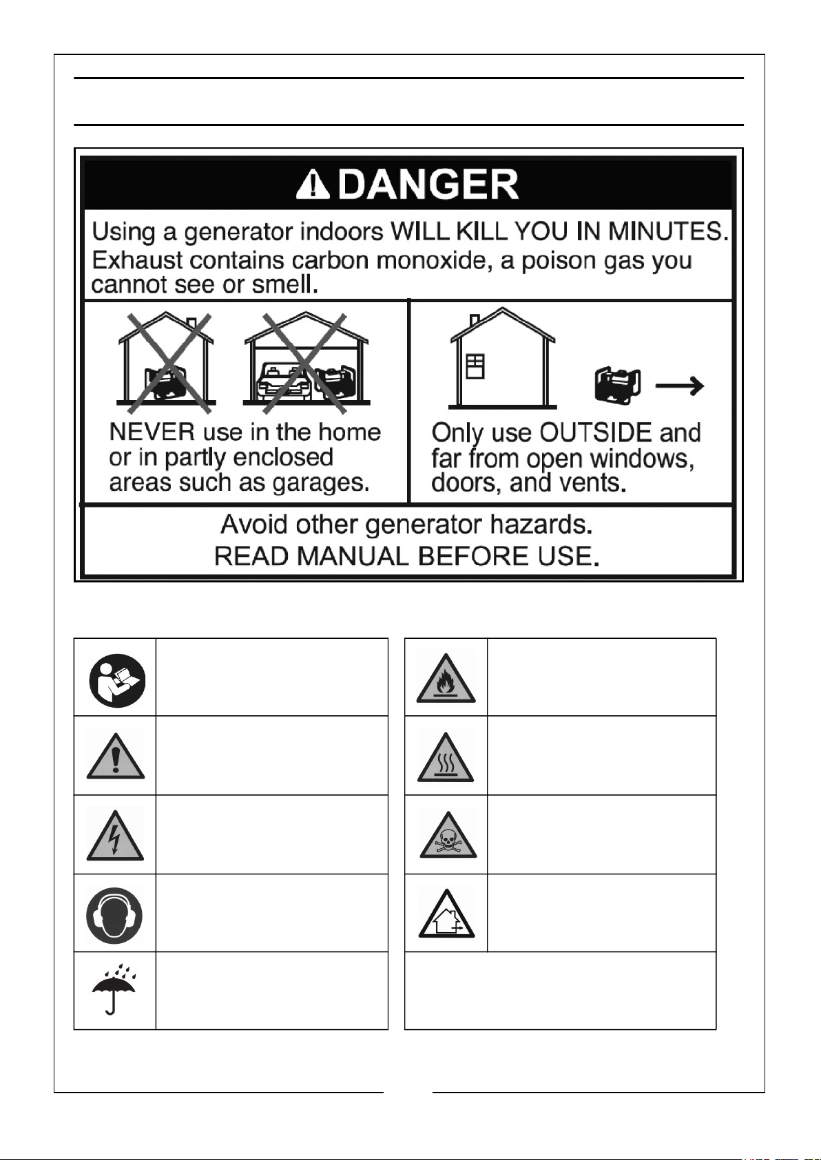
SAFETY SYMBOLS
Read Instruction manual
before use
Caution - The user should
be aware of a general
hazard
Dangerous voltage. Risk of
electric shock
Wear ear defenders For outdoor use only. DO
DO NOT use in the wet. These symbols are to be found
DANGER - highly
flammable liquid.
Engine and exhaust
become hot during use DO NOT touch
Poisonous fumes - DO
NOT use in an enclosed
space.
NOT expose to rain.
on the product.
4
Parts & Service: 020 8988 7400 / E-mail: [email protected] or [email protected]
Page 5

WORK AREA
1. ALWAYS use in a well ventilated area.
2. ALWAYS position the exhaust outlet away from people.
3. NEVER use indoors or in a confined space.
4. ALWAYS keep children away from the generator.
POSITIONING THE GENERATOR
1. ONLY use the folding handles to wheel the generator into position. NEVER use
them to lift the generator off the ground.
2. ALWAYS leave a least a 1m gap between the generator and any surrounding
building or structure.
3. ALWAYS ensure the generator is on a dry, solid, flat surface.
4. ALWAYS ensure the surrounding area is free from any material that could burn or
be damaged by heat.
5. NEVER move or tilt the generator whilst it is switched on.
FIRE PREVENTION
1. ALWAYS switch the engine OFF when refuelling. Allow generator to cool for at
least 2 minutes before removing the fuel cap. Loosen cap slowly to relieve
pressure in the tank.
2. ALWAYS refuel away from any source of heat.
3. ALWAYS refuel in a well ventilated area.
4. ONLY use standard unleaded petrol.
5. DO NOT overfill the fuel tank. DO NOT fill to the very top of the tank and leave
room for petrol expansion.
6. NEVER smoke whilst refuelling and avoid smoking or using a naked flame near
the generator.
7. DO NOT operate near an open flame, heat or flammable materials. This
generator may emit highly flammable and explosive petrol vapours.
8. NEVER start the engine if there is spilled fuel. Any spillage must be wiped clean
and the generator allowed to dry before attempting to start the engine.
PREVENTION OF ELECTRIC SHOCK
1. NEVER use the generator in wet conditions unless it is well protected/covered.
Under these conditions, adequate ventilation MUST be provided.
2. NEVER operate the generator with wet hands.
5
Parts & Service: 020 8988 7400 / E-mail: [email protected] or [email protected]
Page 6

3. NEVER use water or any other liquid to clean the generator.
4. ALWAYS ground the generator before using it to maximise safety, see ‘Ground
The Generator’ section on page 14.
5. ALWAYS use a ground fault circuit interrupter (GFCI) (not included) in highly
conductive areas such as metal decking or steel work. Extension cords with an inline GFCI are recommended for these operations.
GENERAL SAFETY RULES FOR GENERATORS
1. ALWAYS ensure the applied load does not exceed the generator rating.
Overloading the generator is dangerous and could cause damage.
ALWAYS
2.
3. ALWAYS ensure the generator reaches operating speed before connecting a
load.
4. NEVER allow the generator to run out of fuel when a load is connected.
5. NEVER transport the generator with fuel in the tank.
disconnect the generator when carrying out any maintenance.
6. DO NOT connect to a commercial or residential power supply; e.g. ring main.
7. DO NOT touch hot parts. This generator produces heat when running.
Temperatures near the exhaust can exceed 150°F/65°C. Allow the generator to
cool down after use before touching the engine or areas of the generator that
become hot during use.
8. If any part of the generator, electrical device or power cable is broken, damaged
or defective, make sure it is repaired or replaced before using. Service or repair of
the generator should only be performed by a qualified technician.
9. NEVER modify the generator in any way. Modifying or using the generator for any
other purpose for which it is not designed may result in serious injury, machine
damage and voiding of the warranty.
10. ALWAYS turn off all connected electrical devices before stopping the generator.
11. ALWAYS turn the engine switch to the ‘OFF’ position when the engine is not
running.
6
Parts & Service: 020 8988 7400 / E-mail: [email protected] or [email protected]
Page 7
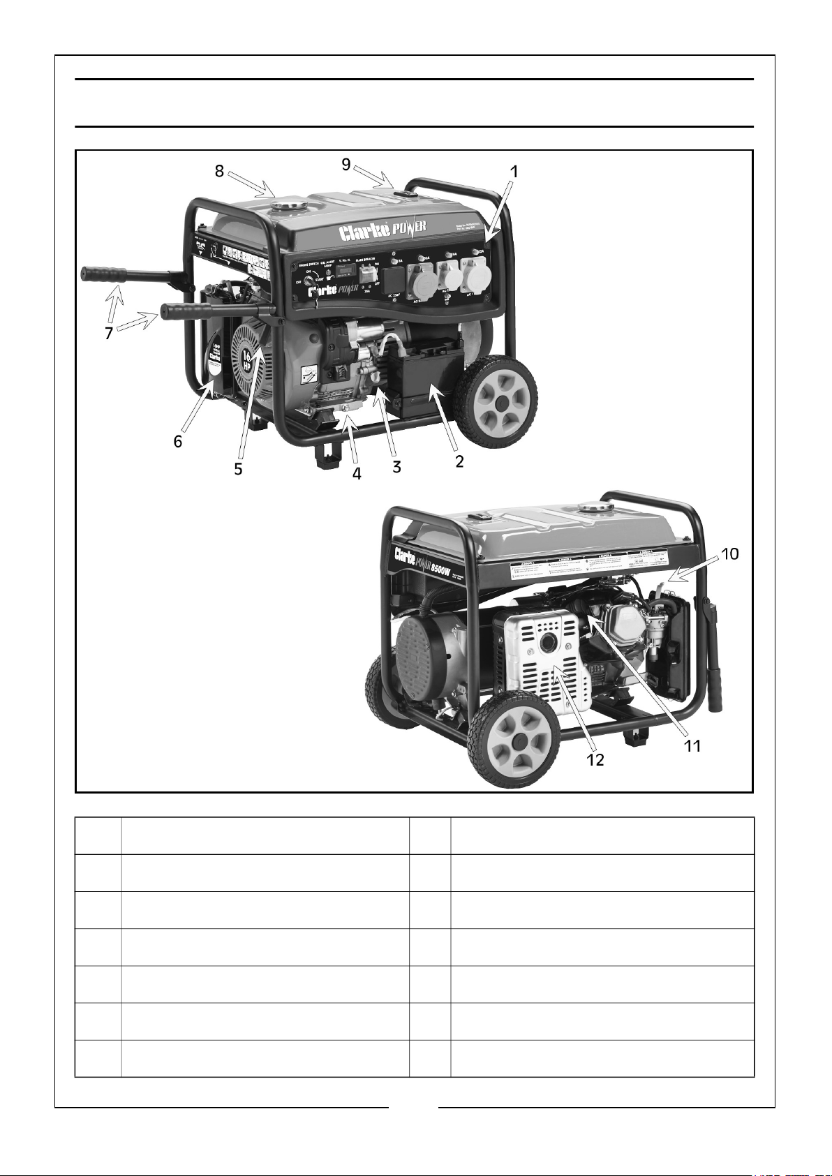
GENERATOR OVERVIEW
NO DESCRIPTION NO DESCRIPTION
1 Control Panel 7 Folding Handles
2 Battery 8 Fuel Cap
3 Oil Fill Cap/Dipstick 9 Fuel Gauge
4 Oil Drain Plug 10 Choke
5 Recoil Starter 11 Spark Plug
6 Air Filter 12 Muffler/Exhaust
7
Parts & Service: 020 8988 7400 / E-mail: [email protected] or [email protected]
Page 8
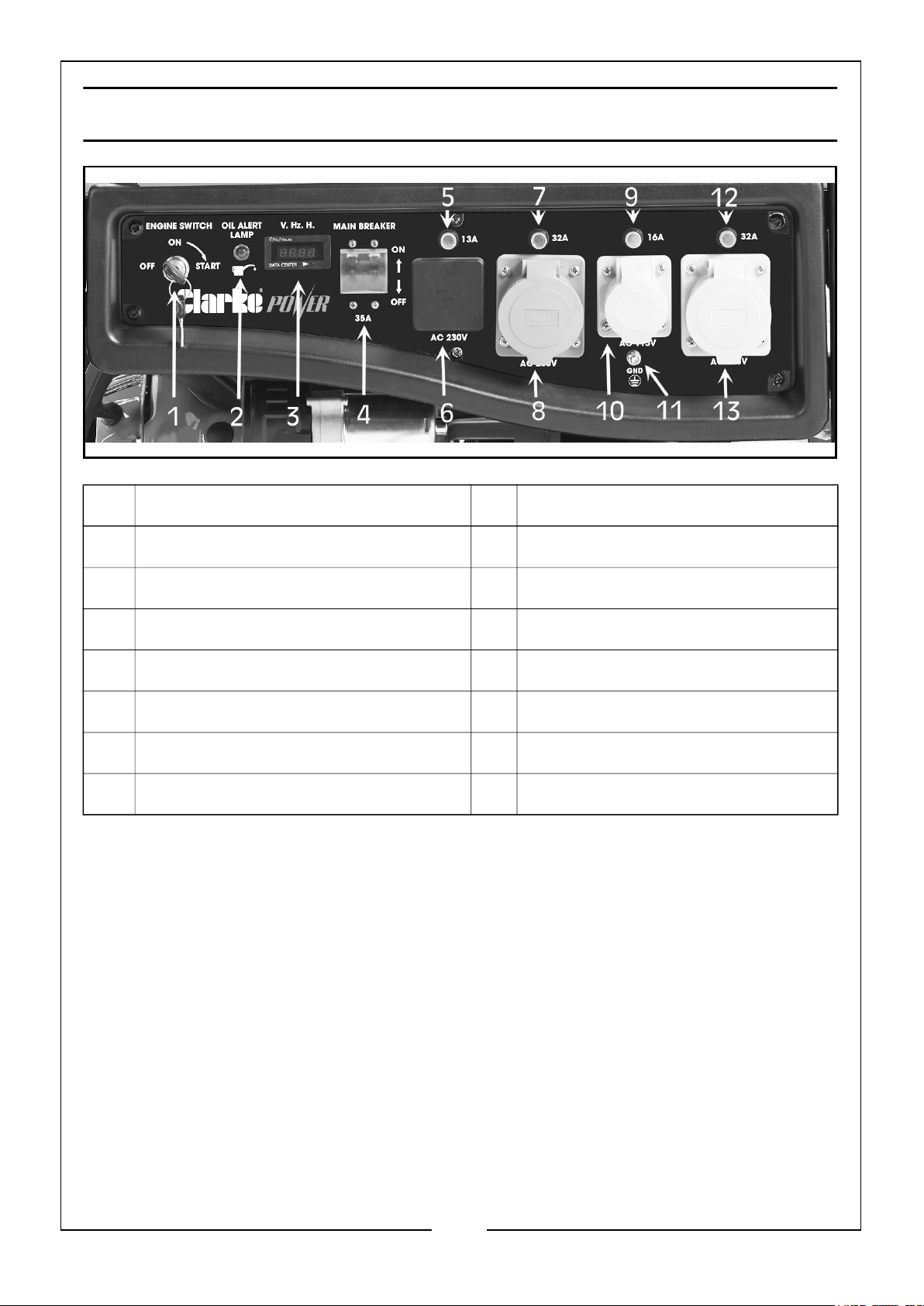
CONTROL PANEL OVERVIEW
NO DESCRIPTION NO DESCRIPTION
1 Electric Start Ignition 8 32A, 240V Plug Socket
2 Oil Level Alert Lamp 9 16A Breaker Switch
3 Data Centre (Volts & Hertz per hour) 10 16A, 110V Plug Socket
4 Main Breaker Switch 11 Earth Grounding Terminal
5 13A Breaker Switch 12 32A Breaker Switch
6 AC 230V Plug Socket 13 32A, 110V Plug Socket
7 32A Breaker Switch
8
Parts & Service: 020 8988 7400 / E-mail: [email protected] or [email protected]
Page 9
UNPACKING
Unpack your generator and check to ensure the following items are present. Should
there be any deficiency or damage caused during transit contact your CLARKE dealer
immediately.
1 x 8.5kW Petrol Generator 2 x Folding Handle c/w fixings
2 x Axle, Washer & R Clip 1 x Spark Plug Box Spanner & Pouch
2 x Wheel & Axle Cover 1 x Tommy Bar
2 x Foot Assembly c/w fixings 1 x Pair of Ignition keys
1 x Lead Acid Battery
(Not Connected, see page 11)
BEFORE USING THE GENERATOR
Attach a suitable earth lead to a good earthing point (see page 14) - e.g. water pipe,
ground spike etc., whenever you use this generator.
Before using your generator check that the generator is:
• In good condition and free from any damage.
• Clean and free from fuel or oil spillage and the fuel system is intact.
• Correctly located for use (see page 5).
NOTE: ALWAYS use a funnel to fill the fuel tank to avoid accidental spillage of
fuel. If fuel is spilled it must be cleaned up before use.
WARNING: ENSURE THERE IS ADEQUATE FUEL IN THE TANK WHEN
USING THE GENERATOR. RUNNING OUT OF FUEL OR STOPPING THE
ENGINE SUDDENLY WITH A LOAD CONNECTED COULD CAUSE
SERIOUS DAMAGE.
WARNING: ALWAYS CHECK THE OIL LEVEL BEFORE STARTING SEE
PAGE 12, FAILURE TO MAINTAIN THE CORRECT OIL LEVEL MAY
SERIOUSLY DAMAGE THE ENGINE.
9
Parts & Service: 020 8988 7400 / E-mail: [email protected] or [email protected]
Page 10
ASSEMBLY
CAUTION: DUE TO THE WEIGHT OF THE GENERATOR, IT IS RECOMMENDED
THAT THE ASSEMBLY IS UNDERTAKEN BY 2 PERSONS.
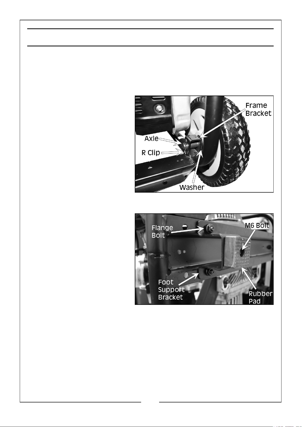
FITTING THE WHEELS
1. Slide the axle through the wheel
and place the washer on the
axle on the frame side of the
wheel.
2. Slide the axle assembly through
the frame bracket and insert the
R clip through the axle hole to
secure in place.
3. Attach the wheel centre cap to
the outside of the wheel.
FITTING THE FEET
1. Insert an M6 bolt through the
rubber pad and secure to the
bottom of the foot support
bracket with M6 nut.
2. Place the foot support bracket to
the underside of the frame and
insert two flange nuts and bolts
and tighten.
10
Parts & Service: 020 8988 7400 / E-mail: [email protected] or [email protected]
Page 11
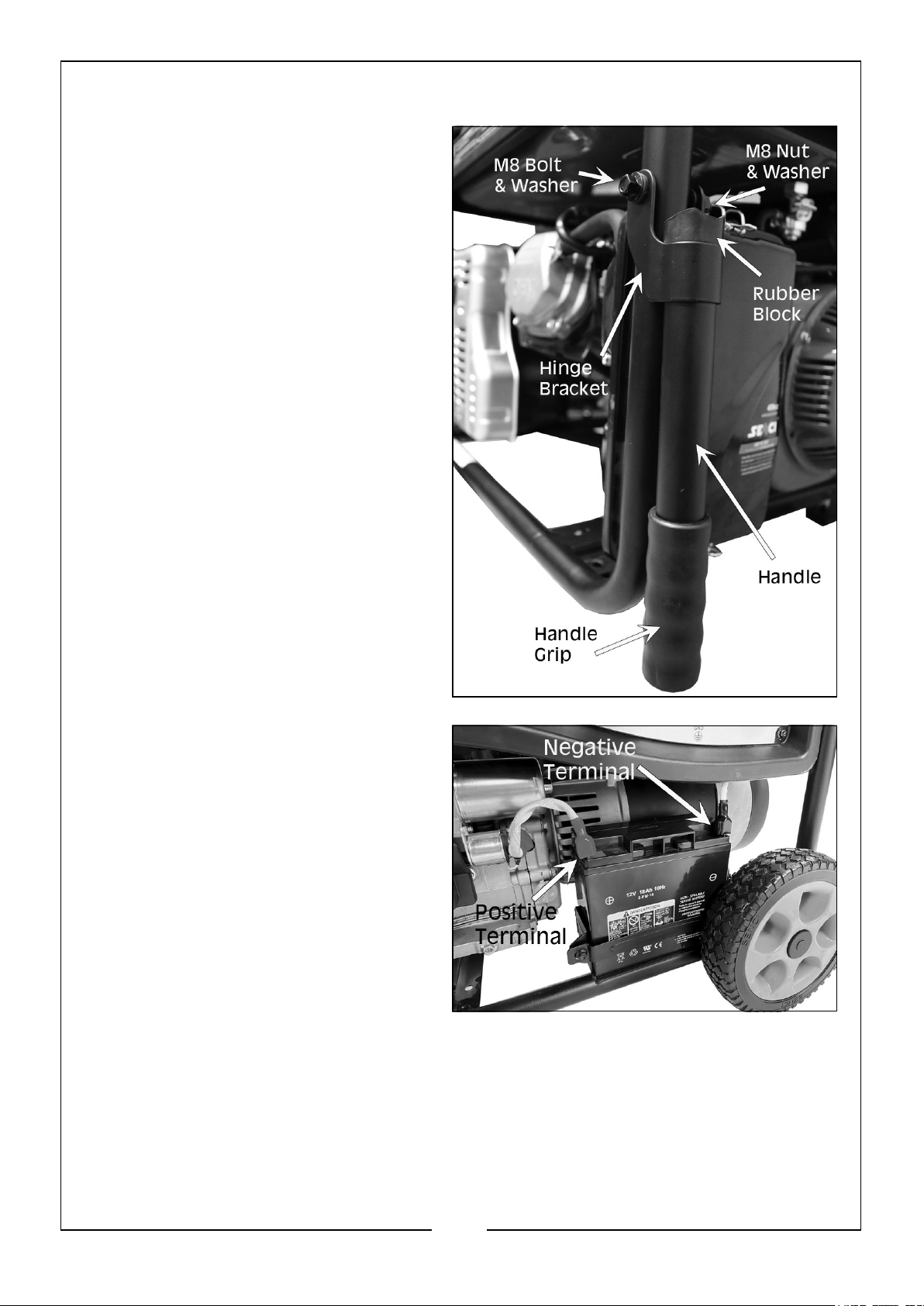
FITTING THE FOLDING HANDLES
1. Insert the rubber block in the end of
the handle with the hinge bracket.
2. Fit the hinge bracket to the
generator frame and secure with M8
washers, nut and bolt.
3. Slide the handle grip onto the end of
the handle.
CONNECTING THE BATTERY
1. Connect the negative wire to the
negative (‘-’ / Black) terminal on the
battery as shown on the right.
2. Connect the positive wire to the
positive (‘+’ / Red) terminal on the
battery.
• Ensure both terminals are covered
by the plastic covers as shown.
11
Parts & Service: 020 8988 7400 / E-mail: [email protected] or [email protected]
Page 12
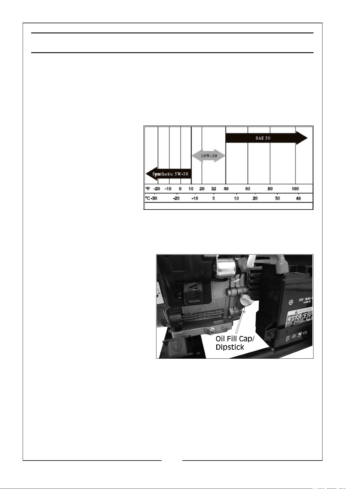
PREPARATION BEFORE OPERATION
ADDING ENGINE OIL
WARNING: THIS GENERATOR IS SOLD WITHOUT OIL
INCLUDED. DO NOT ATTEMPT START THE GENERATOR
WITHOUT INSTALLING THE CORRECT OIL FIRST.
Always check and add the
correct engine oil before
starting the generator. DO NOT
use any special additives. Select
the oil viscosity grade according to
the expected operating temperature (see chart).
• Above 40oF (4oC), use
SAE30 oil.
• Between 10oF (-18oC) & 40oF (4oC), use 10W-30 oil.
• Below 10oF (-18oC), use 5W-30 oil.
1. Place the generator on a flat,
level surface.
2. Clean the area around the oil fill
cap and remove the cap/dipstick.
3. Slowly fill the engine with the
appropriate oil until it reaches
the full mark on the dipstick.
• Stop filling occasionally to
check the oil level & be
careful to not over fill.
4. Replace the oil fill cap/dipstick and finger tighten securely.
NOTE: Check engine oil level before starting each time thereafter.
NOTE: The engine is equipped with a low oil level sensor and the Oil Level
Alert Lamp will light up (see Control Panel on Page 8). This will shut down
the engine automatically when the oil level drops below a specified level.If
the engine shuts down by itself and the fuel tank has enough petrol, check
the engine oil level.
12
Parts & Service: 020 8988 7400 / E-mail: [email protected] or [email protected]
Page 13
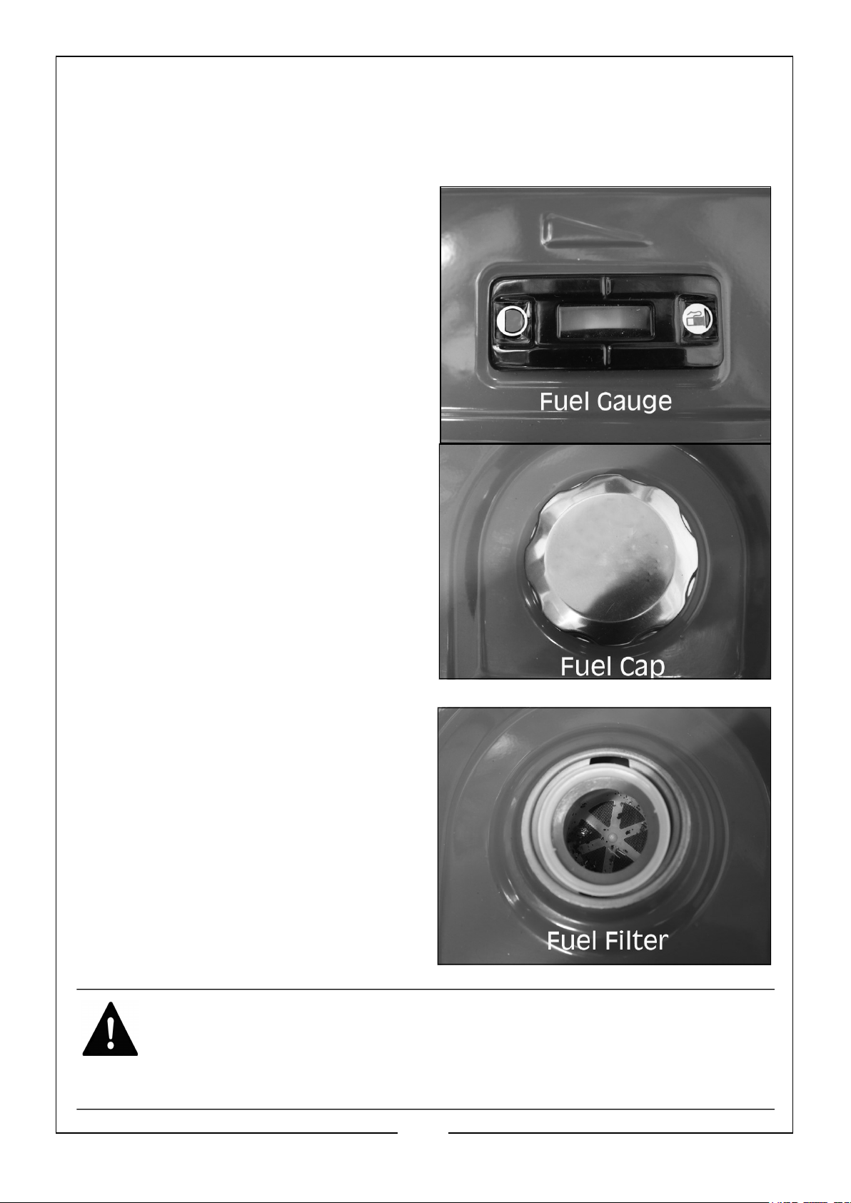
ADDING FUEL
RECOMMENDED FUEL: Only use standard unleaded petrol. DO NOT mix
with oil.
1. Check the fuel level on the fuel gauge.
The fuel gauge will show as red when
you have fuel in the tank turning white
as the fuel level decreases.
2. To add fuel, open the fuel filler cap.
3. Just inside the fuel tank is a fuel filter
which catches any contaminants as you
refuel.
4. Slowly add fuel to the fuel tank
(maximum 20L) watching the fuel level
gauge as you do so.
5. Replace the fuel filler cap securely.
NOTE: DO NOT overfill the fuel tank.
WARNING: ALWAYS REFUEL IN A WELL VENTILATED AREA AWAY
FROM ANY HEAT SOURCES.
WARNING: ALLOW THE UNIT TO COOL DOWN BEFORE REFUELLING.
WARNING: DO NOT LEAVE FUEL WITHIN THE REACH OF CHILDREN.
13
Parts & Service: 020 8988 7400 / E-mail: [email protected] or [email protected]
Page 14
GROUND THE GENERATOR
WARNING: TO REDUCE THE RISK OF ELECTRIC SHOCK AND TO MAXIMISE
SAFETY, THE GENERATOR SHOULD BE PROPERLY GROUNDED BEFORE USE.
Ground the generator by tightening the earth grounding terminal on the front control
panel against a grounding wire. A generally acceptable grounding wire is a No. 14 SWG
(Standard Wire Gauge)(2.108mm) stranded copper wire.
This grounding wire should be connected at the other end to a copper, brass or steel
grounding rod that is driven into the earth. Wire and grounding rods are not included
with the generator
USING YOUR GENERATOR
WARNING: NEVER START OR STOP THE ENGINE WITH ELECTRICAL
DEVICES PLUGGED IN AND TURNED ON. UNPLUG ALL ELECTRICAL
LOADS FROM THE GENERATOR BEFORE STARTING THE ENGINE.
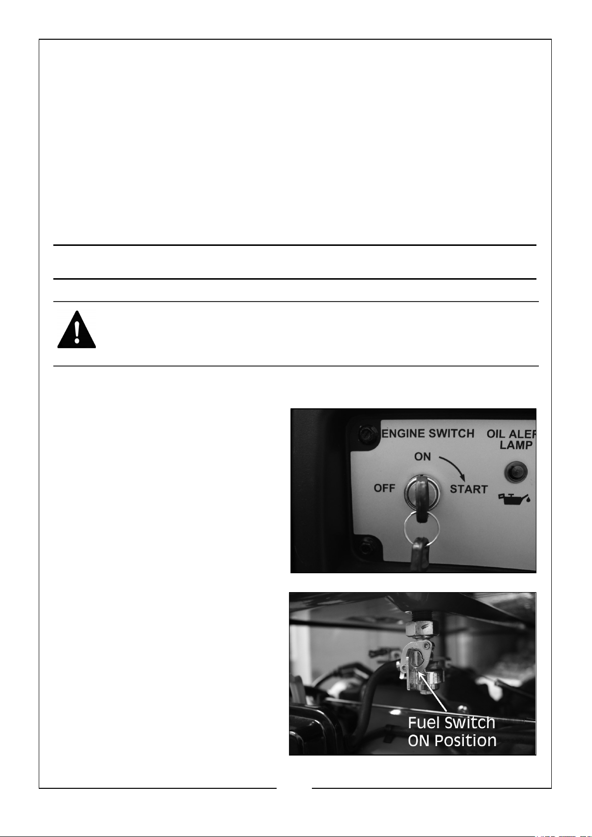
STARTING THE ENGINE
1. Turn the Engine Switch to the ‘ON’
position.
2. Turn the Fuel Switch to the ‘ON’
position.
14
Parts & Service: 020 8988 7400 / E-mail: [email protected] or [email protected]
Page 15
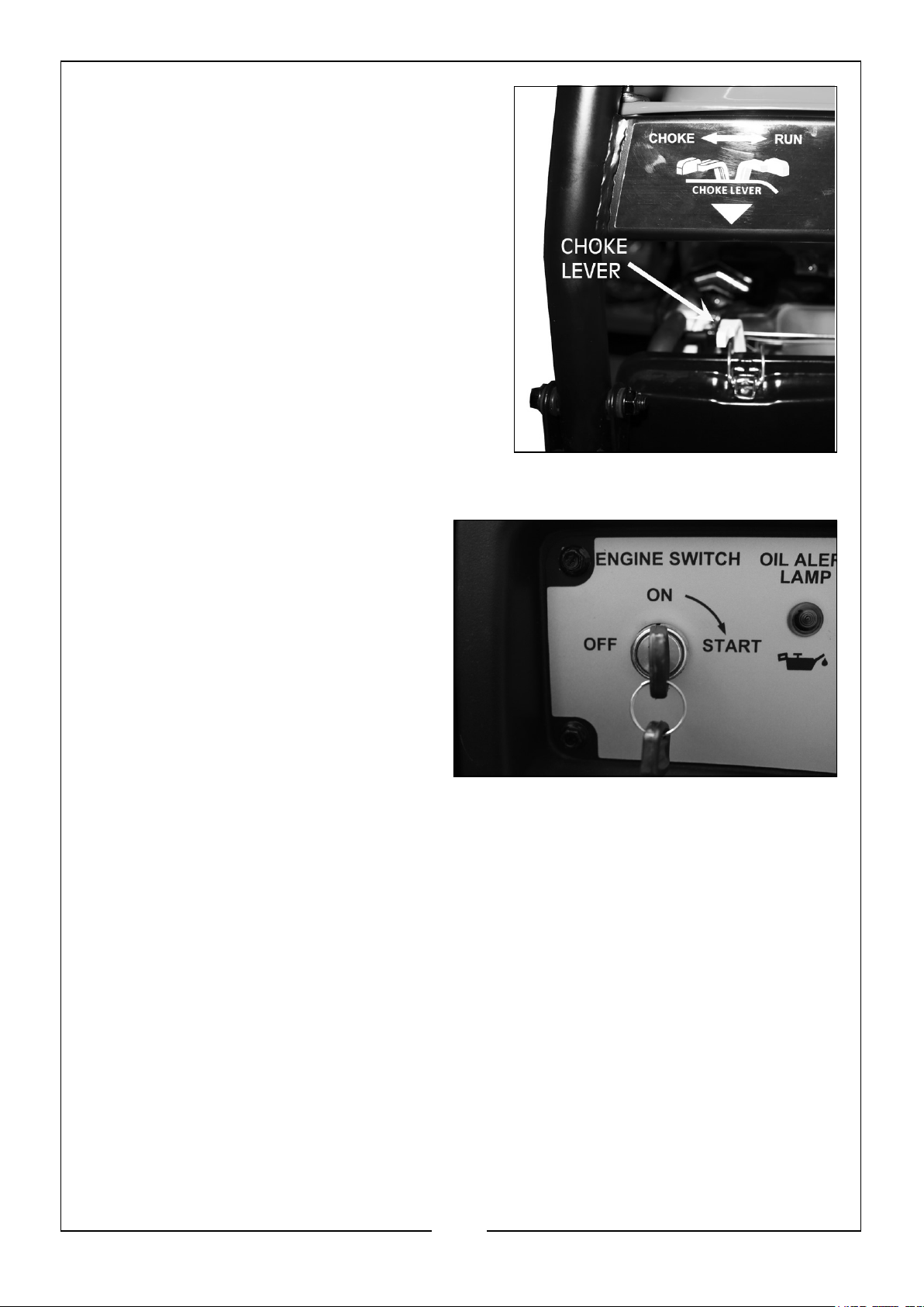
3. Move the Engine Choke Lever to the
‘CHOKE’ position.
FOR ELECTRIC START
1. Insert the key into the ignition.
2. Turn and hold key in the start switch
to the ‘Start’ position until the
generator starts.
NOTE: To prolong the life of the
starter components, DO NOT hold
the key in the ‘Start’ position for
more than 15 seconds, and pause
for at least 1 minute between
starting attempts.
3. Once the engine has started, move the choke lever to 1/2 CHOKE position until
the engine runs smoothly and then fully to the ‘RUN’ position. If the engine
falters, move the choke lever back to the 1/2 CHOKE position until the engine runs
smoothly, then back to the ‘RUN’ position.
NOTE: If the battery is discharged, use the manual recoil start instructions on
page 14-16.
NOTE: If the engine fires, but does not continue to run, move the choke lever
to the ‘OFF’ position and repeat starting instructions.
15
Parts & Service: 020 8988 7400 / E-mail: [email protected] or [email protected]
Page 16
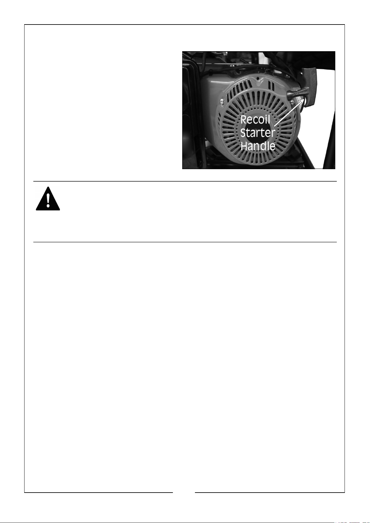
FOR MANUAL RECOIL START
1. Firmly grasp the recoil starter handle
and pull slowly until increased
resistant is felt.
2. Then pull rapidly up.
3. Once the engine has started, move
the choke lever to 1/2 CHOKE
position until engine runs smoothly
and then fully to the ‘RUN’ position. If
the engine falters, move the choke
lever back to the 1/2 CHOKE position
until engine runs smoothly, then back
to the ‘RUN’ position.
WARNING: STARTER CORD KICKBACK (RAPID RETRACTION) WILL
PULL YOUR HAND AND ARM TOWARD THE ENGINE FASTER THAN
YOU CAN LET GO, WHICH COULD CAUSE SERIOUS INJURY. WHEN
STARTING THE ENGINE, PULL THE CORD SLOWLY UNTIL
RESISTANCE IS FELT AND THEN PULL RAPIDLY TO AVOID
KICKBACK.
CONNECTING ELECTRICAL DEVICES
Follow the steps below to properly connect your device(s) to the generator.
1. Before connecting electrical devices, allow the generator to run for a few minutes
to stabilise the speed and voltage output.
2. Select the device with the highest wattage and make sure it is turned off. Plug the
device into the generator and then turn the device on. Allow the engine to
stabilise.
3. Repeat step 2 to plug in each additional device. DO NOT attempt to plug in and
start multiple devices at the same time.
GENERATOR CAPACITY
Make sure the generator can supply enough running (rated) and starting (max.) watts
for the items you will power at the same time. Follow these simple steps.
1. Select the items you will want to power at the same time.
2. Add together the running (rated) watts of these items. This is the amount of
power the generator must produce to keep the items running.
3. Estimate how many starting (max.) watts you will need. Starting wattage is the
short burst of power needed to start electric motor driven tools such as a circular
saw or refrigerator. Because not all motors start at the same time, total starting
16
Parts & Service: 020 8988 7400 / E-mail: [email protected] or [email protected]
Page 17
(max.) watts can be estimated by adding only the items with the highest
additional starting (max.) to the total rated watts.
Example only:
Tool/Appliance Running Watts Additional Starting Watts
Refrigerator 700 1350
Portable Fan 40 120
Laptop 250 250
46 in. Flat Screen TV 190 190
Light (75 Watts) 75 75
1255 Total Running Watts 1350 Highest Starting Watts
Total Running Watts: 1255
Highest Starting Watts: +1350
Total Starting Watts Needed = 2605
To prolong the life of the generator and attached devices, it is important to take care
when adding electrical loads to the generator. There should be nothing connected to
the generator outlets before starting its engine. The correct and safe way to manage
the generator power is to sequentially add loads as follows:
1. With nothing connected to the generator, start the engine as described on pages
14-16 of this manual.
2. Plug in and turn on the first load, preferably the largest load you have.
3. Allow the generator output to stabilise (engine runs smoothly and any attached
device operates properly).
4. Plug in and turn on the next load.
5. Again, allow the generator to stabilise.
6. Repeat steps 4 & 5 for each additional load.
NEVER add more loads than the generator capacity. Take special care to consider
surge loads in generator capacity as previously described.
17
Parts & Service: 020 8988 7400 / E-mail: [email protected] or [email protected]
Page 18
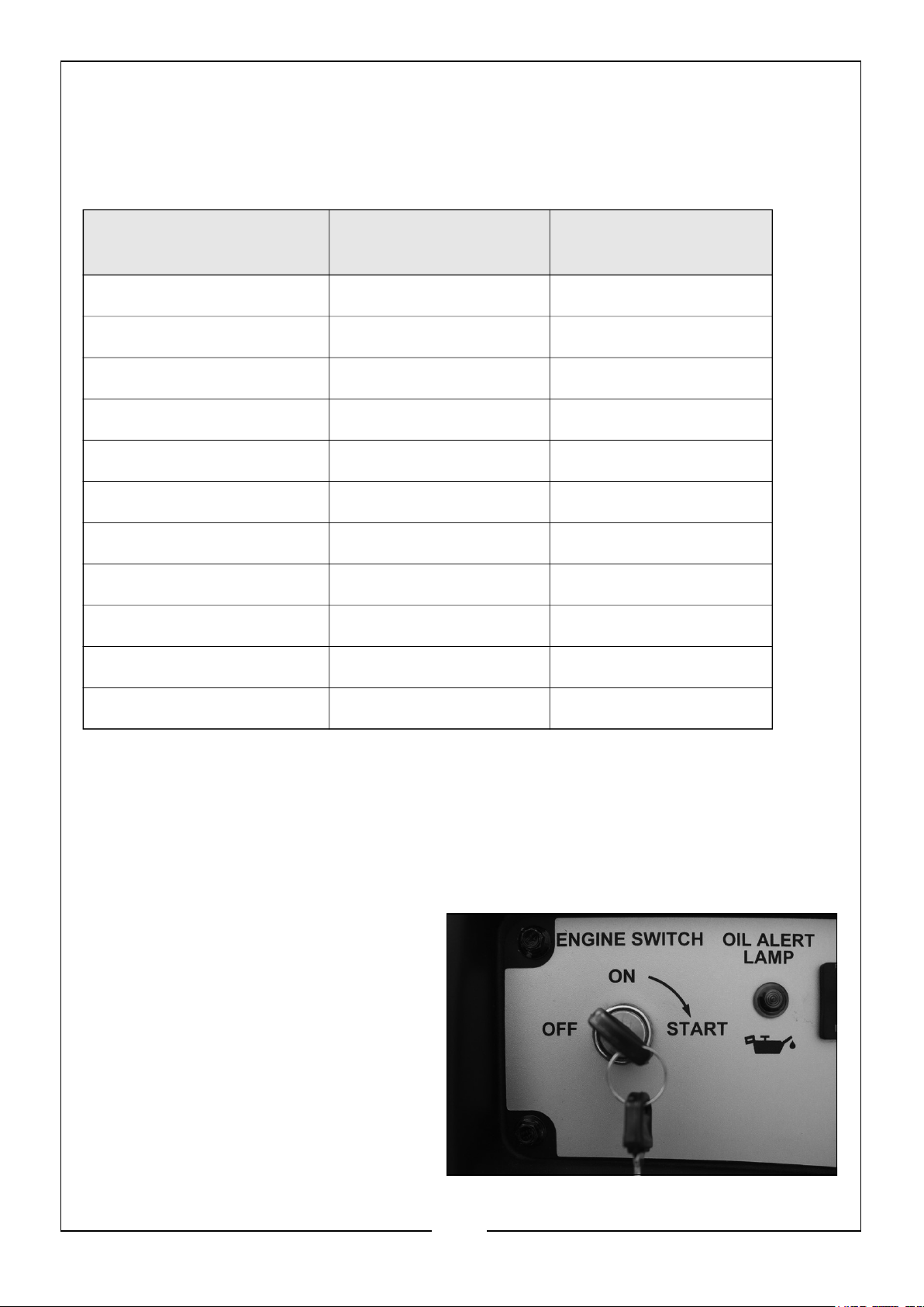
The chart below serves as a reference only for the estimated wattage
requirements of common electrical devices. However, DO NOT solely reply on this chart
as all appliances are built differently, ALWAYS check the wattage listed on the electrical
device before consulting this chart:
Tool/Appliance Rated (Running)
Watts
Surge (Starting)
Watts
Hot Plate 2500 0
Saw - Circular 1500 1500
Saw - Mitre 1200 1200
Microwave 1000 0
Well Water Pump 1000 1000
Sump Pump 800 1200
Refrigerator/Freezer 800 1200
Computer 800 0
Television 500 0
Box Fan 300 600
Light Bulb 75 0
SHUTTING DOWN THE GENERATOR
Shut off all loads then unplug the devices from the generator panel. NEVER start or
stop the engine with electrical devices plugged in and turned on.
1. Let the engine run at no-load for several minutes to stabilise the internal
temperature of the engine and generator.
2. Move the ON/OFF switch to the ‘OFF
‘position.
18
Parts & Service: 020 8988 7400 / E-mail: [email protected] or [email protected]
Page 19
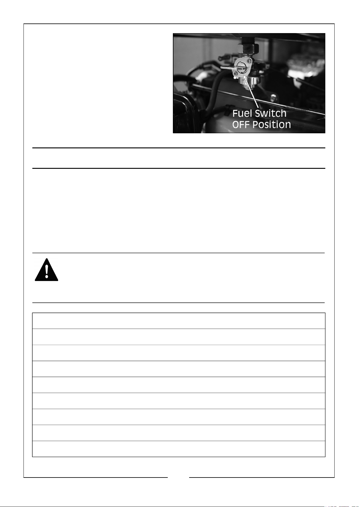
3. Turn the fuel switch to the ‘OFF’
position.
MAINTENANCE & TROUBLESHOOTING
MAINTENANCE SCHEDULE
Proper routine maintenance of the generator will help prolong the life of the machine.
Please perform maintenance checks and operations according to the Maintenance
Schedule below. If there are any questions about the
maintenance procedures listed in this manual, please contact the CLARKE
service centre.
WARNING: NEVER PERFORM MAINTENANCE OPERATIONS WHILE
THE GENERATOR IS RUNNING. BEFORE MAINTENANCE OR
SERVICING THE GENERATOR, TURN OFF THE GENERATOR,
DISCONNECT ALL DEVICES AND ALLOW THE GENERATOR TO COOL
DOWN
First 5 Hours of use
• Change engine oil (see page 21)
Every 8 Hours of use or Daily
• Clean debris (see page 20)
• Check engine oil level (see page 12)
• Check fuel level (see page 13)
Every 25 Hours or use or Yearly
• Clean engine air filter (see page 23)
Every 50 Hours or use or Yearly
19
Parts & Service: 020 8988 7400 / E-mail: [email protected] or [email protected]
Page 20
• Change engine oil (see page 21)
Yearly
• Replace engine air filter (see page 23)
• Service fuel valve
• Clean and service spark plug and replace if necessary (see page 22)
• Inspect muffler (exhaust) and spark arrester (see page 23)
• Clean cooling system
GENERATOR MAINTENANCE
Generator maintenance consists of keeping the unit clean and dry. Operate and store
the unit in a clean dry environment where it will not be exposed to excessive dust, dirt,
moisture or any corrosive vapours. Cooling air slots in the
generator must not become clogged with snow, leaves, or any other foreign material.
Check the cleanliness of the generator frequently and clean when dust, dirt, oil, moisture or other foreign substances are visible on its exterior
surface.
WARNING: NEVER INSERT ANY OBJECT OR TOOL THROUGH THE
AIR COOLING SLOTS, EVEN IF THE ENGINE IS NOT RUNNING.
WARNING: DO NOT USE A GARDEN HOSE TO CLEAN THE
GENERATOR. WATER CAN ENTER THE ENGINE FUEL SYSTEM AND
CAUSE PROBLEMS. IN ADDITION, IF WATER ENTERS THE
GENERATOR THOUGH THE COOLING AIR SLOTS, SOME WATER WILL
BE RETAINED IN VOIDS AND CREVICES OF THE ROTOR AND
STATOR WINDING INSULATION. WATER AND DIRT BUILD UP ON
THE GENERATOR INTERNAL WINDINGS WILL EVENTUALLY
DECREASE THE INSULATION RESISTANCE OF THE WINDINGS.
TO CLEAN THE GENERATOR
1. Use a damp cloth to wipe exterior surfaces clean.
2. A soft bristle brush may be used to loosen caked on dirt, oil etc.
3. A vacuum cleaner may be used to pick up loose dirt and debris.
4. Low pressure air (DO NOT exceed 25psi and ALWAYS wear eye protection) may
be used to blow away dirt. Inspect the cooling air slots and openings on the
generator. These openings must be kept clean and unobstructed.
20
Parts & Service: 020 8988 7400 / E-mail: [email protected] or [email protected]
Page 21
CHANGING THE OIL
Change the oil after the first 5 hours of operation, then every 50 hours thereafter. If
running this unit under dirty or dusty conditions, or in extremely hot weather, change
the oil more often.
WARNING: HOT OIL MAY CAUSE BURNS. ALLOW THE ENGINE TO
COOL BEFORE DRAINING THE OIL. AVOID PROLONGED OR
REPEATED SKIN EXPOSURE WITH OIL. THOROUGHLY WASH
EXPOSED AREAS WITH SOAP.
Use the following instructions to change the oil while the engine is still warm.
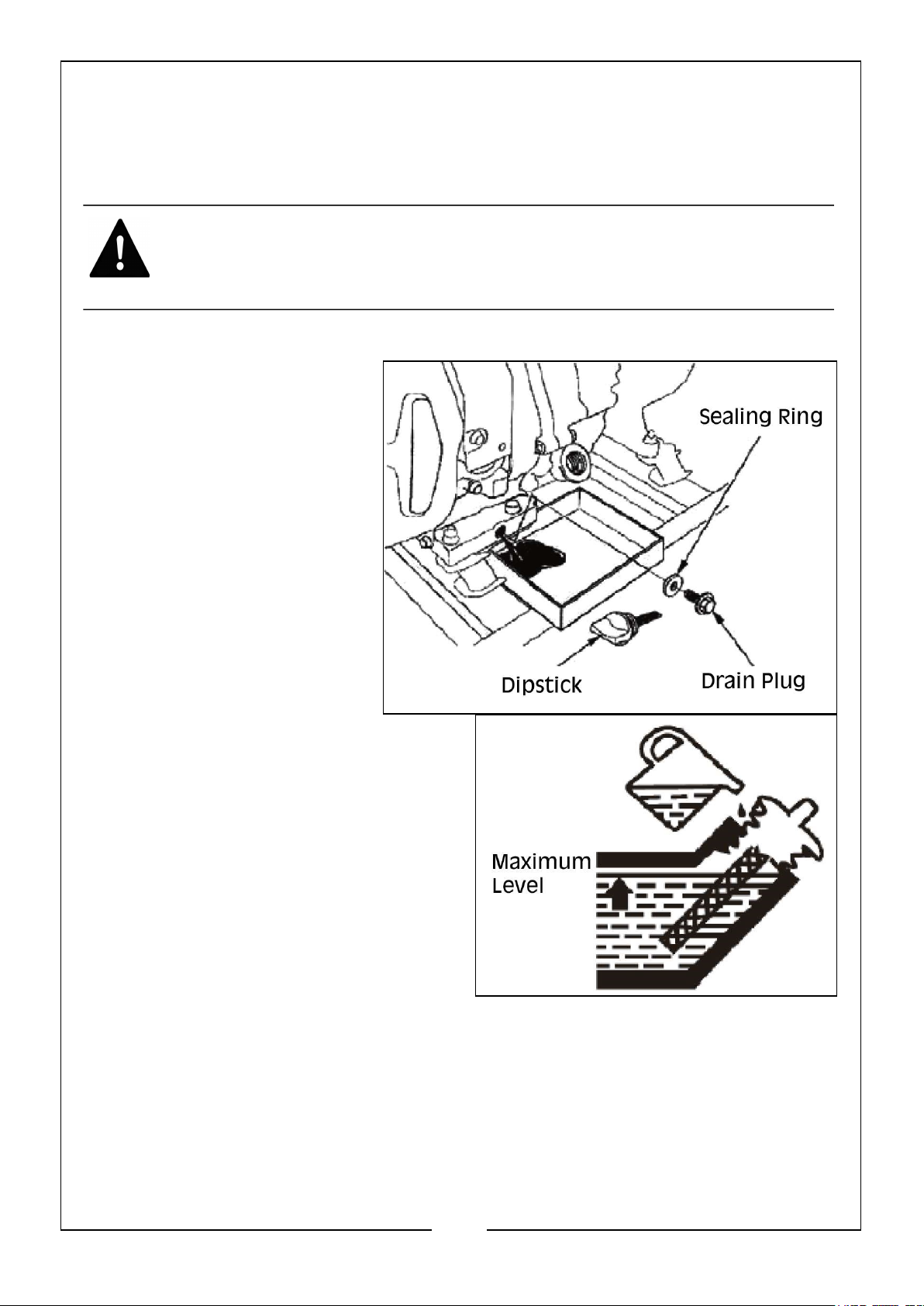
1. Clean area around the oil
drain plug.
2. Place a suitable oil container
under the oil drain plug.
3. Remove the dipstick and oil
drain plug from the engine
and drain oil into the
container.
4. Once the oil has completely
drained, re-install the oil
drain plug and tighten
securely.
5. Refill the engine with the
recommended oil (see page 12).
6. Wipe up any spilled oil.
7. Dispose of used oil at an appropriate
recycling centre.
ENVIRONMENTAL PROTECTION
One of the most damaging sources of pollution is oil, DO NOT throw away used engine
oil in with your domestic rubbish or pour it down drains or sinks. Place it in a leak proof
container and take it to your local waste disposal site.
21
Parts & Service: 020 8988 7400 / E-mail: [email protected] or [email protected]
Page 22
INSPECTING OR REPLACING THE SPARK PLUG
Use spark plug F6TC, BPR4ES or equivalent. Replace the spark plug once every year.
This will help the engine start easier and run better.
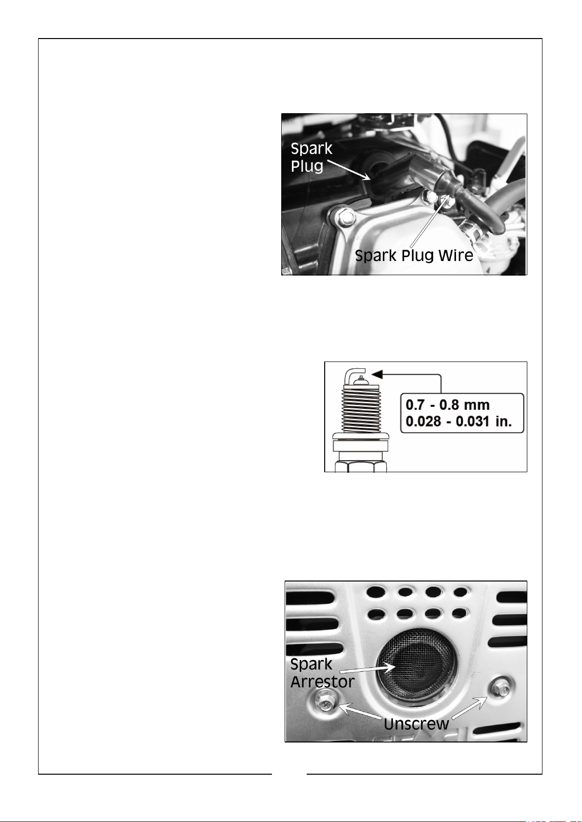
1. Make sure the generator is off and
remove the spark plug wire.
2. Use the spark plug spanner that is
supplied to unscrew and then
carefully remove the spark plug
from the engine.
NOTE: There is limited space for the
spanner to turn, use the
spanner tommy bar to gain
leverage to loosen the plug.
3. Visually inspect the spark plug. if it is cracked or chipped, or if the electrodes are
worn or burned, discard it and replace with a new spark plug.
4. If re-using the spark plug, use a wire brush to clean any dirt from around the
spark plug base, then re-gap the spark plug.
5. Measure the plug gap with a spark plug
gap gauge. the gap should be 0.7 - 0.8mm
(0.028 - 0.031in). Carefully adjust the gap
if necessary.
6. Screw the spark plug back into the spark
plug hole using the spark plug spanner.
DO NOT over-tighten. Recommended
tightening a spark plug is 1/2 to 3/4 of a
turn (15ft/lb torque/20.33Nm) after the spark plug gasket contacts the spark plug
hole.
7. Reinstall the spark plug wire and cap.
INSPECTING OR REPLACING THE SPARK ARRESTOR
1. Shut off the generator and allow the
muffler (exhaust) to cool down
completely before servicing the spark
arrestor.
2. Unscrew the spark arrestor screen.
3. Clean the spark arrestor screen with
a small wire brush and reinstall.
4. Replace the spark arrestor if it is
damaged.
22
Parts & Service: 020 8988 7400 / E-mail: [email protected] or [email protected]
Page 23
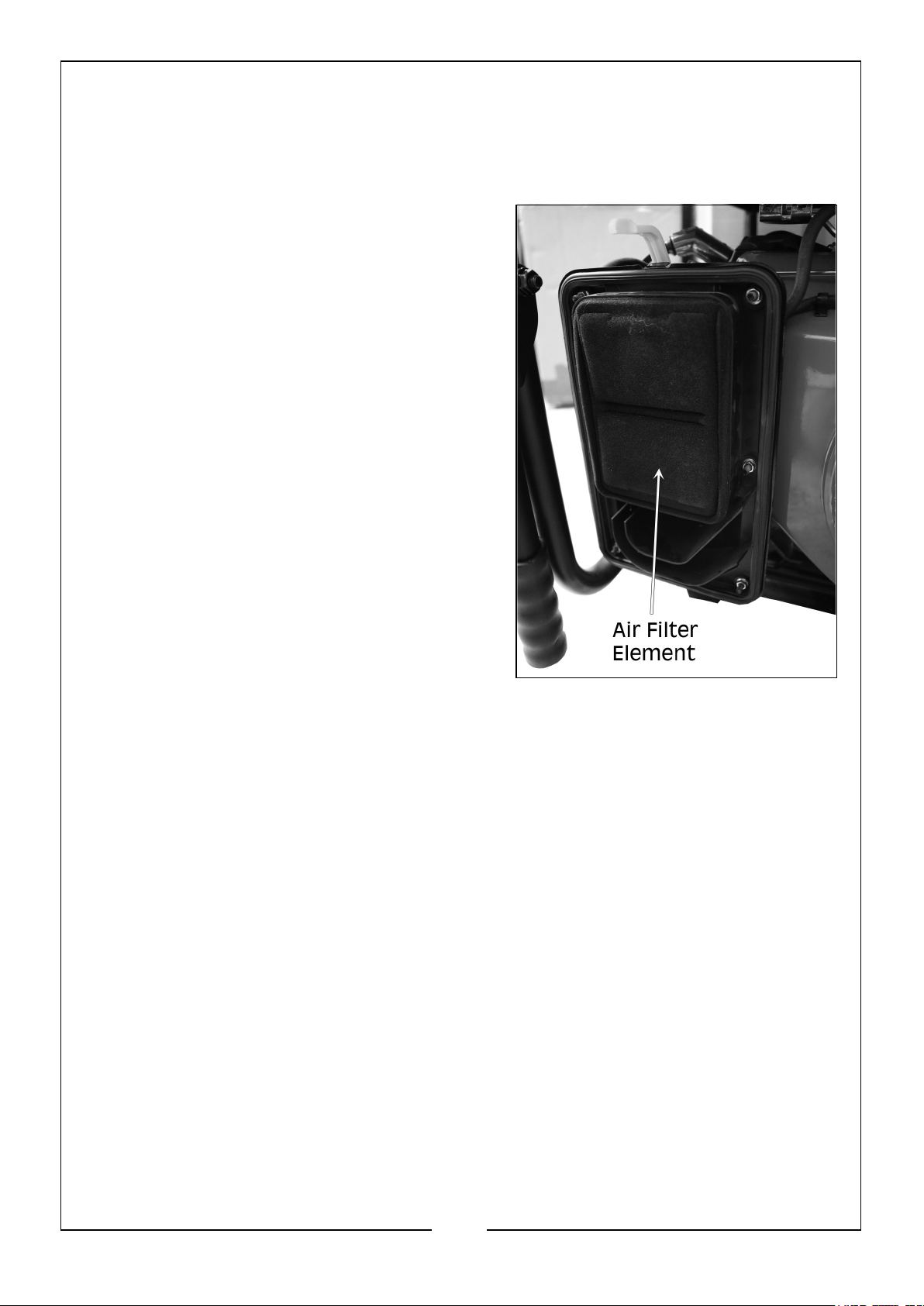
INSPECTING OR REPLACING THE AIR FILTER
The engine will not run properly and may be damaged if using a dirty air filter. Replace
the air filter once a year. Clean or replace more often if operating under dusty conditions.
1. Remove air filter cover by unclipping the top
and bottom.
2. Take the cover off and remove the foam air
filter element from the casing. Wipe
excessive oil and any dirt from inside the air
filter casing.
3. Check and clean the foam air filter element.
Good elements can be washed in soapy
water. Dry the element in a clean cloth (DO
NOT twist it). Add a few drops of engine oil
to the air filter element and spread it evenly.
• If the air filter element has been
damaged, replace it with a new one.
Contact the CLARKE service centre.
4. Reinstall the air filter element within the
casing and reinstall the air filter cover.
23
Parts & Service: 020 8988 7400 / E-mail: [email protected] or [email protected]
Page 24

TROUBLESHOOTING
PROBLEM POSSIBLE CAUSE SOLUTION
The generator
fails to start
Battery not charged Charge battery
Engine switch is in the OFF
position
Turn engine switch to the ON
position
No Fuel Fill fuel tank (see page 13)
Stale petrol or water in petrol Drain entire system and refill
with fresh fuel (see page 25-26)
Engine oil level is low Engine is equipped with Low Oil
Shutoff. If engine oil level is low,
it must be filled before unit will
start. Check engine oil level and
fill if necessary (see page 12)
Fuel switch is in the OFF
position
Spark plug faulty, fouled, or
improperly gapped
Turn fuel switch to the ON position (see page 14)
Replace spark plug (see page
22)
Engine lacks
power
The generator is
difficult to start
Engine stored without
treating or draining petrol, or
Drain fuel. Refuel with fresh petrol (see page 25-26)
refueled with bad petrol
Dirty fuel filter Replace fuel filter or contact the
CLARKE service
department (see page 13)
Dirty air filter Check air filter element. Clean
or replace as needed (see page
23)
Engine stored without
treating or draining petrol, or
refueled with bad petrol
Drain fuel. refuel with fresh petrol (see page 25-26). If
problem continues, contact the
CLARKE service
department
The air filter is dirty. Clean the air filter (see page
23).
24
Parts & Service: 020 8988 7400 / E-mail: [email protected] or [email protected]
Page 25
PROBLEM POSSIBLE CAUSE SOLUTION
AC receptacle
does not work
If this does not solve your problem contact the CLARKE service department.
OUTPUT indicator is OFF, and
OVERLOAD indicator is ON
AC Circuit protector has tripped Check AC load and reset AC cir-
GFCI (Ground Fault Circuit
Interrupter) system has
activated (if used)
Item plugged in is defective Try a different device.
Check AC load (see page 16-
18). Stop and restart the
engine. Check the cooling air
inlet. Stop and restart the
engine.
cuit breakers (see Control Panel
on page 8)
Reset the GFCI
STORAGE
The generator should be started at least once every seven days and be allowed to run
for at least 30 minutes. If this can’t be done and the unit must be stored for more than
30 days, use the following information as a guide to prepare it for
storage.
WARNING: NEVER STORE THE ENGINE WITH FUEL IN THE TANK,
INDOORS OR IN AN ENCLOSED, POORLY VENTILATED AREA. DRAIN
FUEL INTO AN APPROVED CONTAINER OUTDOORS, AWAY FROM
OPEN FLAME. BE SURE THE ENGINE IS COOL. DO NOT SMOKE.
DRAINING THE FUEL SYSTEM
It is important to avoid gum deposits from forming in the essential fuel system parts
such as the carburettor, fuel hose or tank during storage. To avoid engine problems, the
fuel system should be emptied before storage of 30 days or
longer, as follows:
1. Remove all fuel from the generator, by draining the fuel tank as follows:
• Place a suitably sized fuel container under the fuel drain plug on the
carburettor.
25
Parts & Service: 020 8988 7400 / E-mail: [email protected] or [email protected]
Page 26
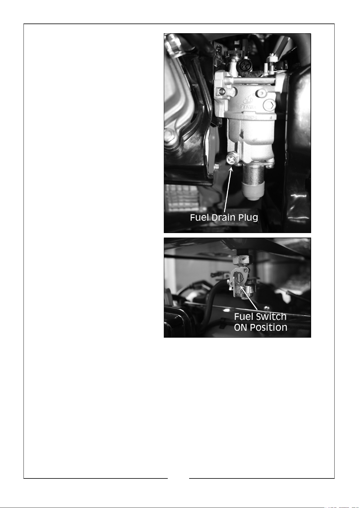
• Unscrew the fuel drain plug.
• Turn the fuel switch to the
‘ON’ position to open the
drain.
• Once the fuel has drained,
replace the drain plug and turn
the fuel switch to the ‘OFF’
position.
2. Start and run the engine until the engine stops from lack of fuel.
3. While engine is still warm, drain the oil from the crankcase (see page 21)
4. Remove the spark plug (see page 22) and pour about 1/2 ounce (15ml) of engine
oil into the cylinder. Cover the spark plug hole with a rag and pull the recoil starter
handle a couple of times to lubricate the piston ring and cylinder bore.
5. Reinstall and tighten the spark plug. DO NOT connect the spark plug wire.
6. Clean the generator outer surfaces, using a non-abrasive cleaning solution.
7. Check that the cooling air slots and openings on the generator are open and
unobstructed.
26
Parts & Service: 020 8988 7400 / E-mail: [email protected] or [email protected]
Page 27
8. Store the unit in a clean dry place. If possible, store the unit indoors and cover it
to give protection from dust and dirt, making sure the cover DOES NOT retain
moisture.
9. DO NOT store petrol from one season to the next.
10. Replace the petrol container if it starts to rust. Rust and/or dirt in petrol will cause
problems with the carburettor and fuel system.
11. If it is not practical to empty the fuel tank and the unit is to be stored for some
time, use a commercially available fuel stabiliser added to the petrol to increase
the life of the petrol.
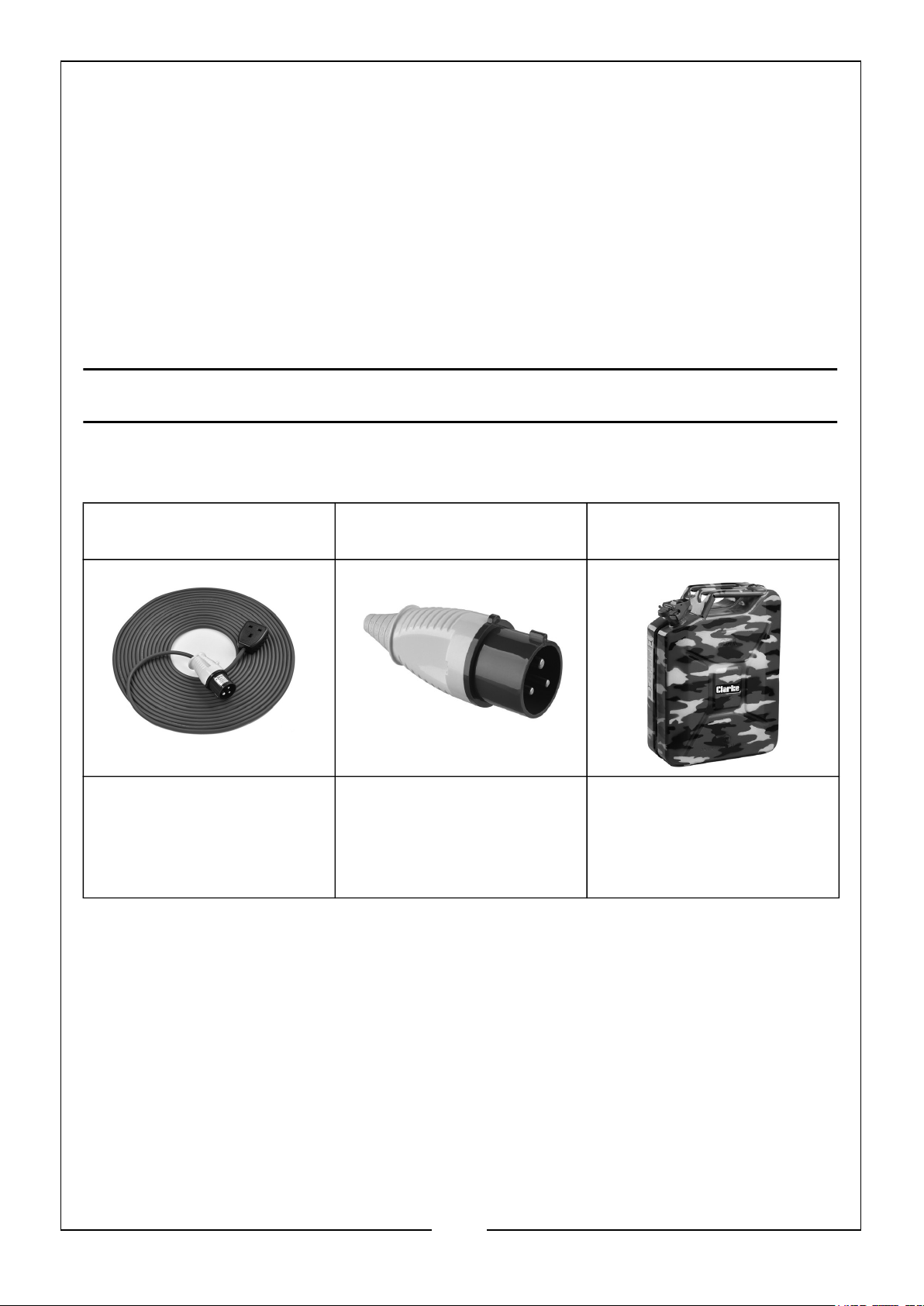
CLARKE GENERATOR ACCESSORIES
Extension Lead - EL16 Generator Plug -
GP32/2
• 14m/1.52mm 230V
Cable.
• 16A Plug to 13A Socket
• Part No. 3220847
• 230V 32A Generator
Plug
• Part No. 6160730
20 Litre Jerry Can -
UN20LC
• 0.8mm Thick Steel
Construction
• Locking Pin on Cap
• Part No. 7650220
27
Parts & Service: 020 8988 7400 / E-mail: [email protected] or [email protected]
Page 28
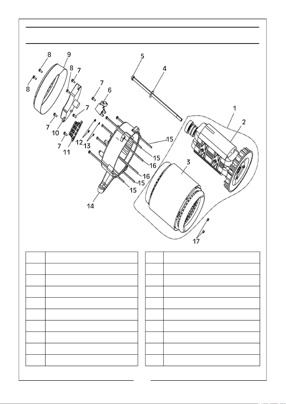
ALTERNATOR DIAGRAM
No Description No Description
01 Alternator Assembly 10 Voltage Regulator
02 Rotor 11 Wiring Board
03 Stator 12 Flat Washer
04 Plain Washer 13 Spring Washer
05 Rotor Bar 14 Alternator Bracket
06 Carbon Brush 15 Flange Bolt
07 Flange Bolt 16 Flange Bolt
08 Flange Bolt 17 Lock Nut
09 Alternator End Cover
28
Parts & Service: 020 8988 7400 / E-mail: [email protected] or [email protected]
Page 29
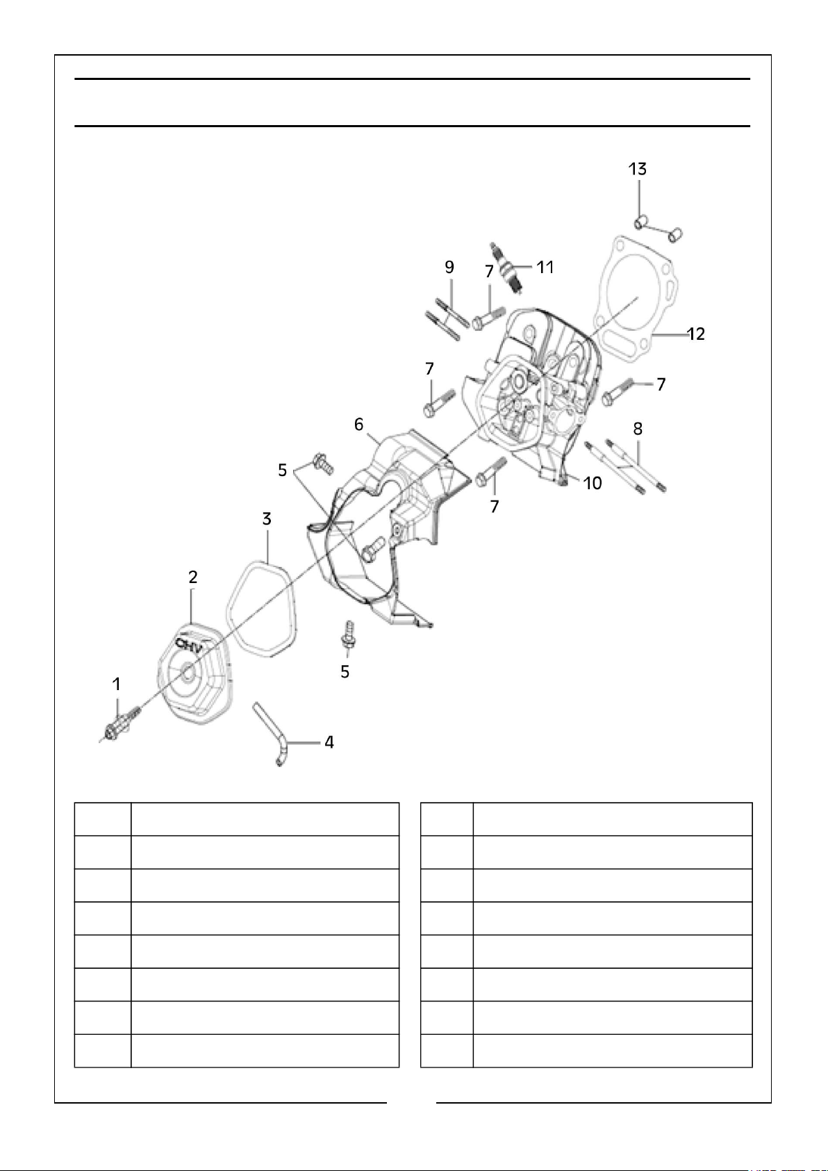
ENGINE DIAGRAM
No Description No Description
01 Bolt, M6 x 60 08 Bolt, Stud, Intake
02 Cover Comp. Head 09 Bolt, Stud, Exhaust
03 Gasket, Head Cover 10 Cylinder Head Compartment
04 Breather Tube 11 Spark Plug
05 Bolt, M6 x 12 12 Head Gasket, Cylinder
06 Cover 13 Dowel Pin
07 Bolt, M10 x 87
29
Parts & Service: 020 8988 7400 / E-mail: [email protected] or [email protected]
Page 30
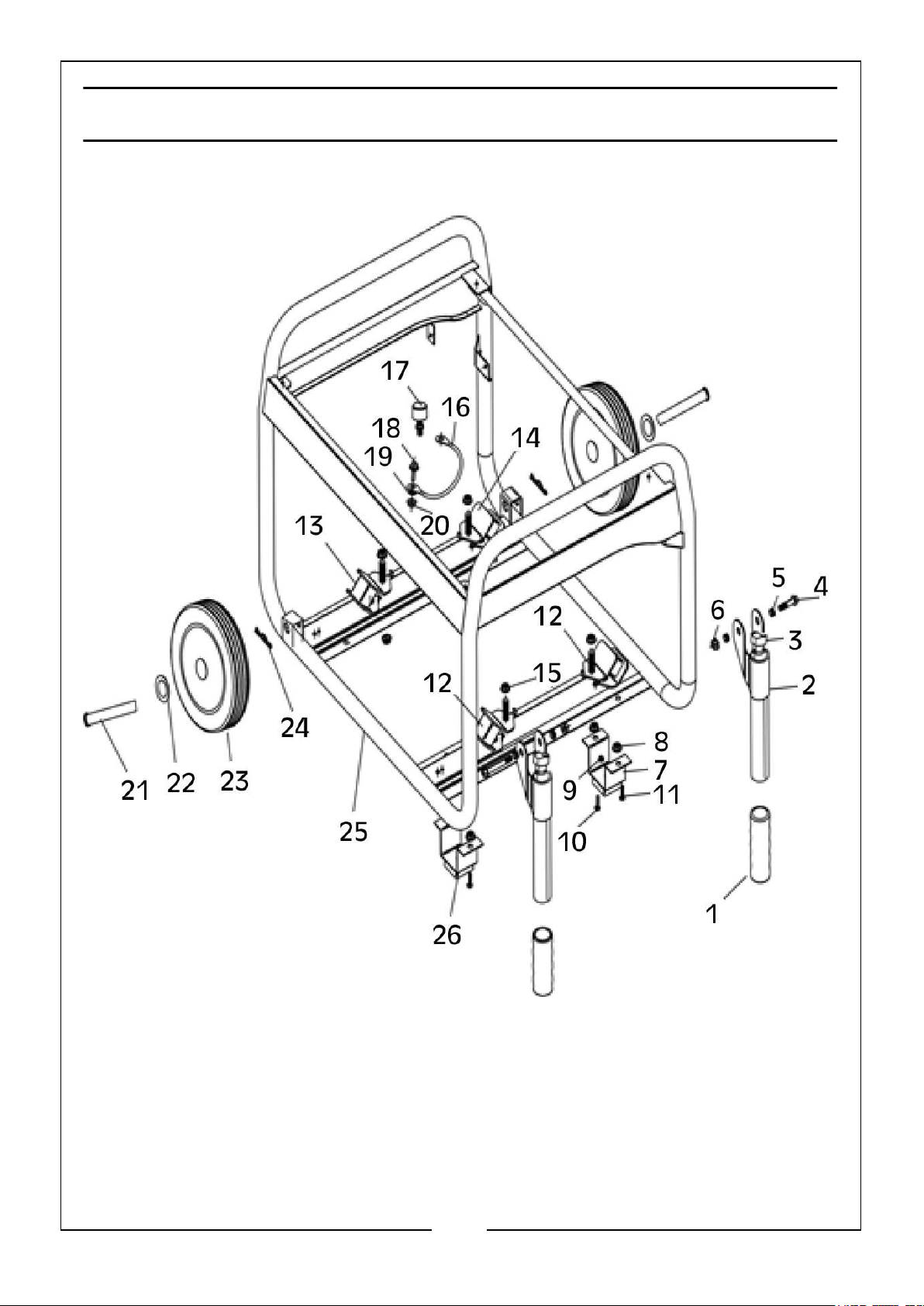
Page 31
No Description No Description
01 Handlebar Rubber Cover 14 Vibration Absorber Rear
02 Handlebar Arm 15 Flange Nut
03 Handlebar Plastic Plug 16 Ground Terminal
04 Flange Bolt 17 Vibration Absorber
05 Washer 18 Flange Bolt
06 Flange Bolt 19 Washer
07 Support 20 Flange Nut
08 Flange Nut 21 Axle
09 Flange Nut 22 Flat Washer
10 Flange Bolt 23 Wheel Assembly
11 Flange Bolt 24 R- Clip, Dowel Pin
12 Vibration Absorber Front 25 Frame Components
13 Vibration Absorber Rear 26 Brackets, Rubber Foot Pad
31
Parts & Service: 020 8988 7400 / E-mail: [email protected] or [email protected]
Page 32
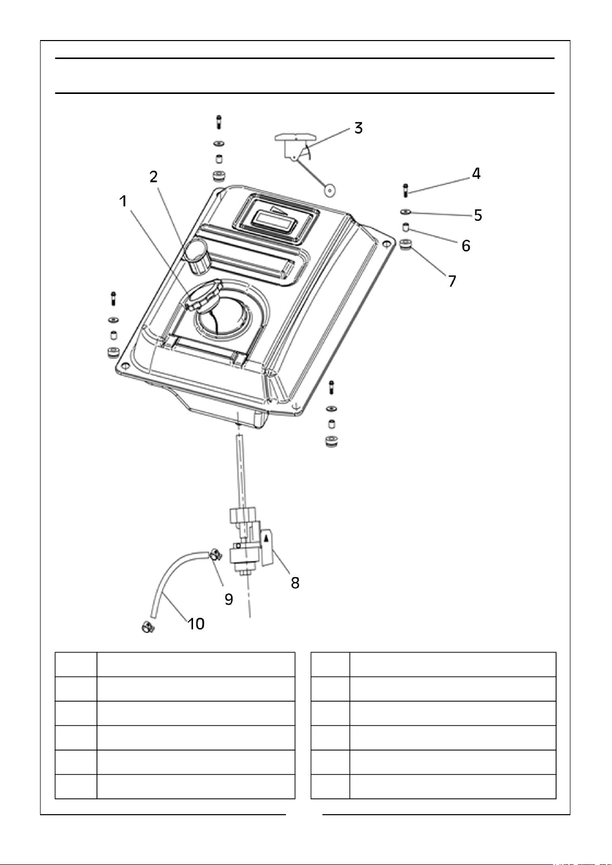
FUEL TANK DIAGRAM
No Description No Description
01 Fuel Tank Cap 06 Bushing
02 Fuel Filter 07 Fuel Tank Rubber Mat
03 Fuel Level Gauge 08 Fuel Valve
04 Flange Bolt 09 Clamp
05 Fuel Tank Washer 10 Fuel Pipe
32
Parts & Service: 020 8988 7400 / E-mail: [email protected] or [email protected]
Page 33
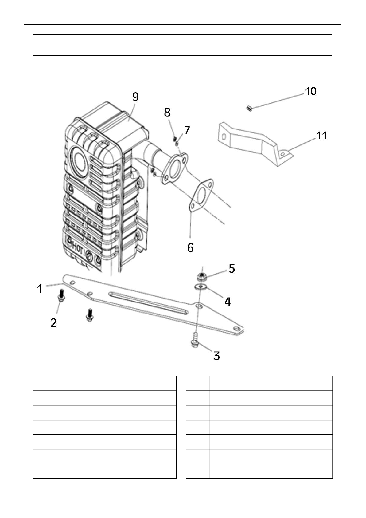
MUFFLER/EXHAUST DIAGRAM
No Description No Description
01 Support Bracket 07 Spring Washer
02 Flange Bolt 08 Hex Nut
03 Flange Bolt 09 Muffler
04 Washer 10 Flange Nut
05 Flange Nut 11 Air Cleaner Bracket
06 Muffler Gasket 12
33
Parts & Service: 020 8988 7400 / E-mail: [email protected] or [email protected]
Page 34
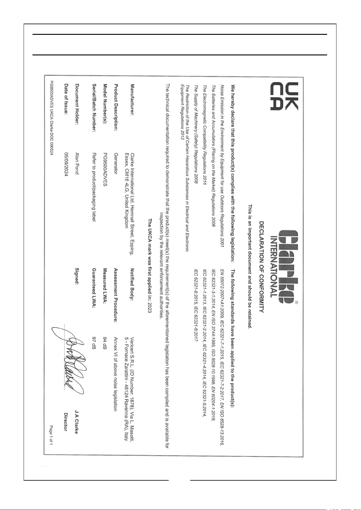
DECLARATION OF CONFORMITY - UKCA
34
Parts & Service: 020 8988 7400 / E-mail: [email protected] or [email protected]
Page 35
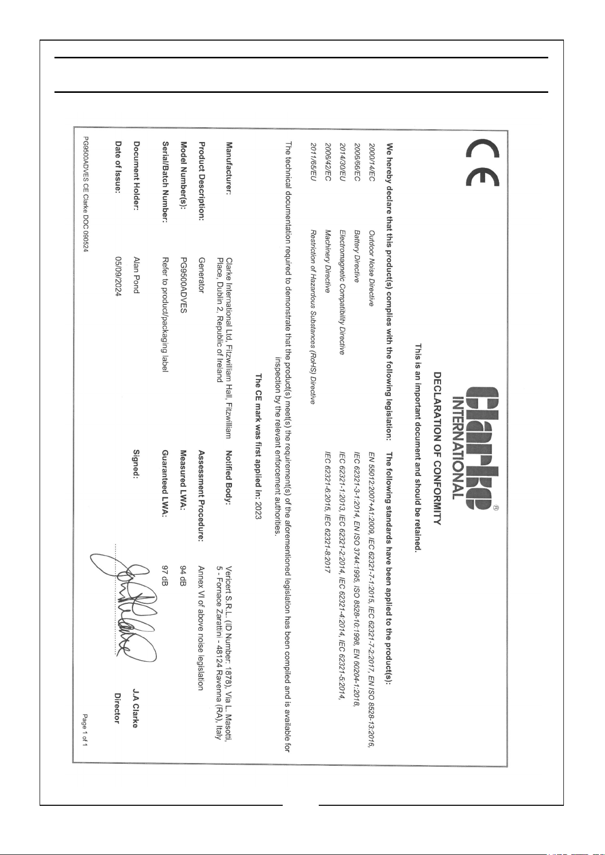
DECLARATION OF CONFORMITY - CE
35
Parts & Service: 020 8988 7400 / E-mail: [email protected] or [email protected]
Page 36

 Loading...