

Page 1
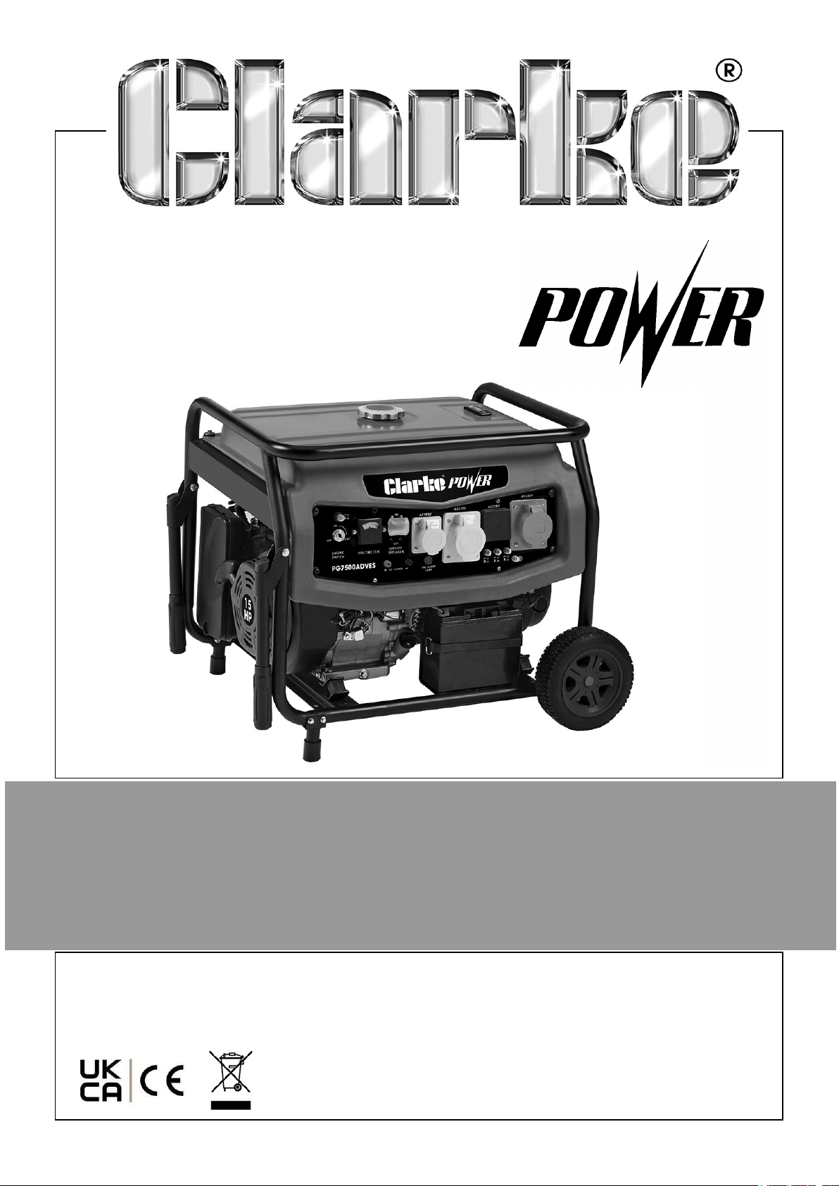
6.5KVA PETROL GENERATOR
MODEL NO: PG7500ADVES
PART NO: 8857857
OPERATION & MAINTENANCE
INSTRUCTIONS
DL1225
Page 2
INTRODUCTION
Thank you for purchasing this CLARKE 6.5KVA Petrol Generator.
Before attempting to use this product, please read this manual thoroughly and follow
the instructions carefully. In doing so you will ensure the safety of yourself and that of
others around you, and you can look forward to your purchase giving you long and
satisfactory service.
GUARANTEE
This product is guaranteed against faulty manufacture for a period of 12 months from
the date of purchase. Please keep your receipt which will be required as proof of
purchase.
This guarantee is invalid if the product is found to have been abused or tampered
with in any way, or not used for the purpose for which it was intended.
Faulty goods should be returned to their place of purchase, no product can be
returned to us without prior permission.
This guarantee does not effect your statutory rights.
ENVIRONMENTAL RECYCLING POLICY
Through purchase of this product, the customer is taking on the obligation
to deal with the WEEE in accordance with the WEEE regulations in relation
to the treatment, recycling & recovery and environmentally sound disposal
of the WEEE.
In effect, this means that this product must not be disposed of with general
household waste. It must be disposed of according to the laws governing Waste
Electrical and Electronic Equipment (WEEE) at a recognised disposal facility.
2
Parts & Service: 020 8988 7400 / E-mail: [email protected] or [email protected]
Page 3

GENERAL SAFETY RULES
WARNING: EXHAUST FUMES CAN BE EXTREMELY DANGEROUS IF
INHALED
WORK AREA
• ALWAYS use in a well ventilated area.
• ALWAYS position the exhaust outlet away from people.
• NEVER use indoors or in a confined space.
• ALWAYS read these safety instructions before using the equipment.
• ALWAYS keep children away from the generator.
POSITIONING THE GENERATOR
1. ALWAYS leave a least a 1m gap between the generator and any surrounding
building or structures.
2. ALWAYS ensure the generator is on a solid, flat surface.
3. ALWAYS ensure the surrounding area is free from any material that could burn or
be damaged by heat.
4. NEVER move or tilt the generator whilst it is switched on.
FIRE PREVENTION
1. ALWAYS switch the engine OFF when refuelling.
2. ALWAYS refuel away from any source of heat.
3. ALWAYS refuel in a well ventilated area.
4. Only use standard unleaded petrol. DO NOT mix oil in with the petrol.
5. NEVER overfill the fuel tank, fill to the level specified, see page 12.
6. NEVER smoke whilst refuelling and avoid smoking or using a naked flame near
the generator.
7. NEVER start the engine if there is spilled fuel. Any spillage must be wiped clean
and the generator allowed to dry before attempting to start the engine.
PREVENTION OF ELECTRIC SHOCK
1. NEVER use the generator in wet conditions unless it is well protected/covered.
Under these conditions, adequate ventilation MUST be provided.
3
Parts & Service: 020 8988 7400 / E-mail: [email protected] or [email protected]
Page 4
2. NEVER operate the generator with wet hands.
3. NEVER use water or any other liquids to clean the generator.
ADDITIONAL SAFETY RULES FOR GENERATORS
1. ALWAYS ensure the applied load does not exceed the generator rating.
Overloading the generator is dangerous and could cause serious damage.
ALWAYS
2.
maintenance.
3. ALWAYS ensure the generator reaches operating speed before connecting a
load.
4. NEVER allow the generator to run out of fuel when a load is connected.
5. NEVER transport the generator with fuel in the tank.
6. DO NOT connect to a commercial or residential power supply; e.g. ring main.
7. NEVER allow the generator air vents to become blocked.
disconnect and turn off the generator when carrying out any
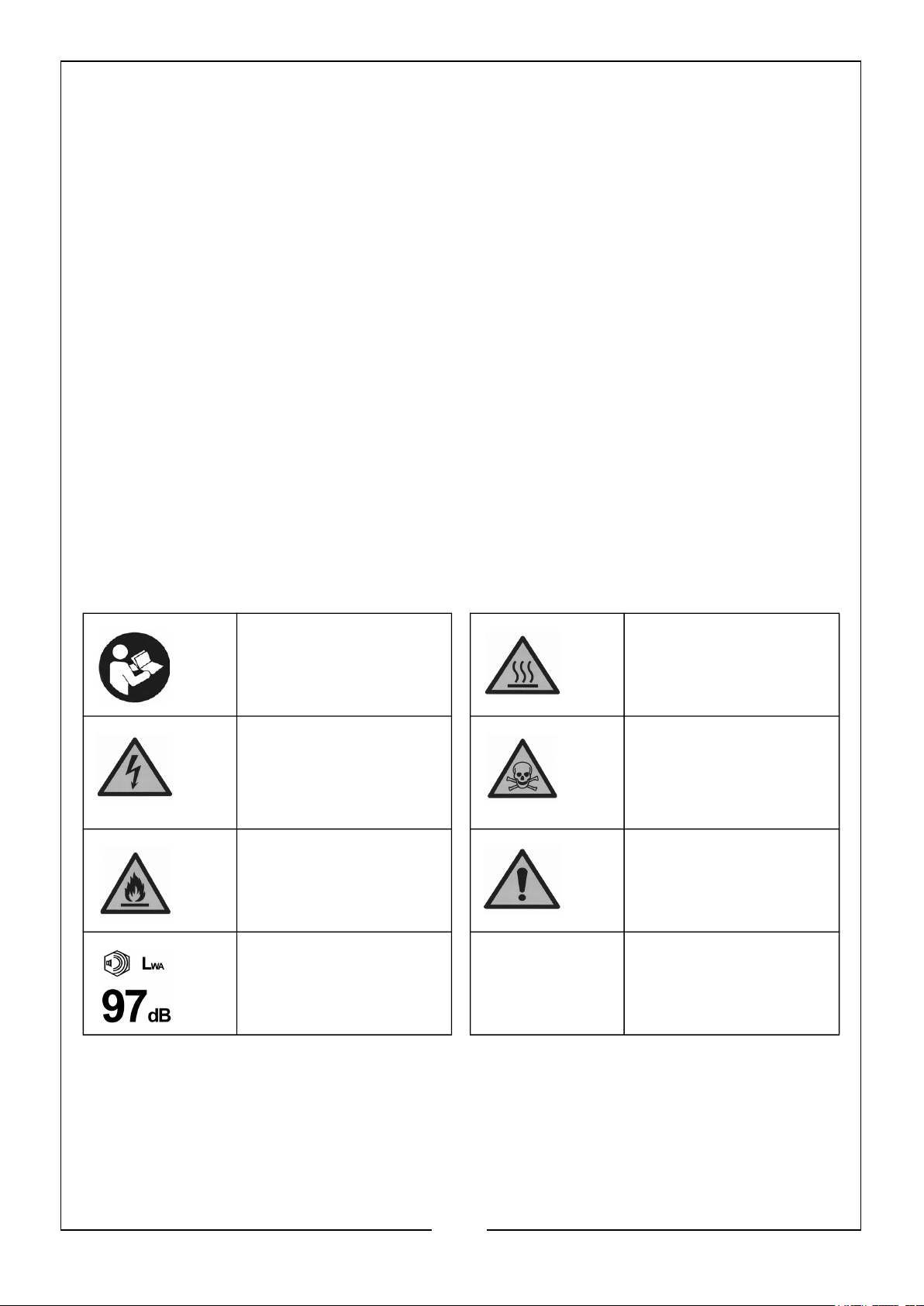
SYMBOLS
Read instruction
manual before use
Dangerous voltage
- risk of
electrocution
Flammable Caution - The user
Caution - High
noise level when in
use
Hot Surface - DO
NOT touch
Poisonous fumes DO NOT use the
generator in an
enclosed space.
should be aware of
a general hazard
4
Parts & Service: 020 8988 7400 / E-mail: [email protected] or [email protected]
Page 5
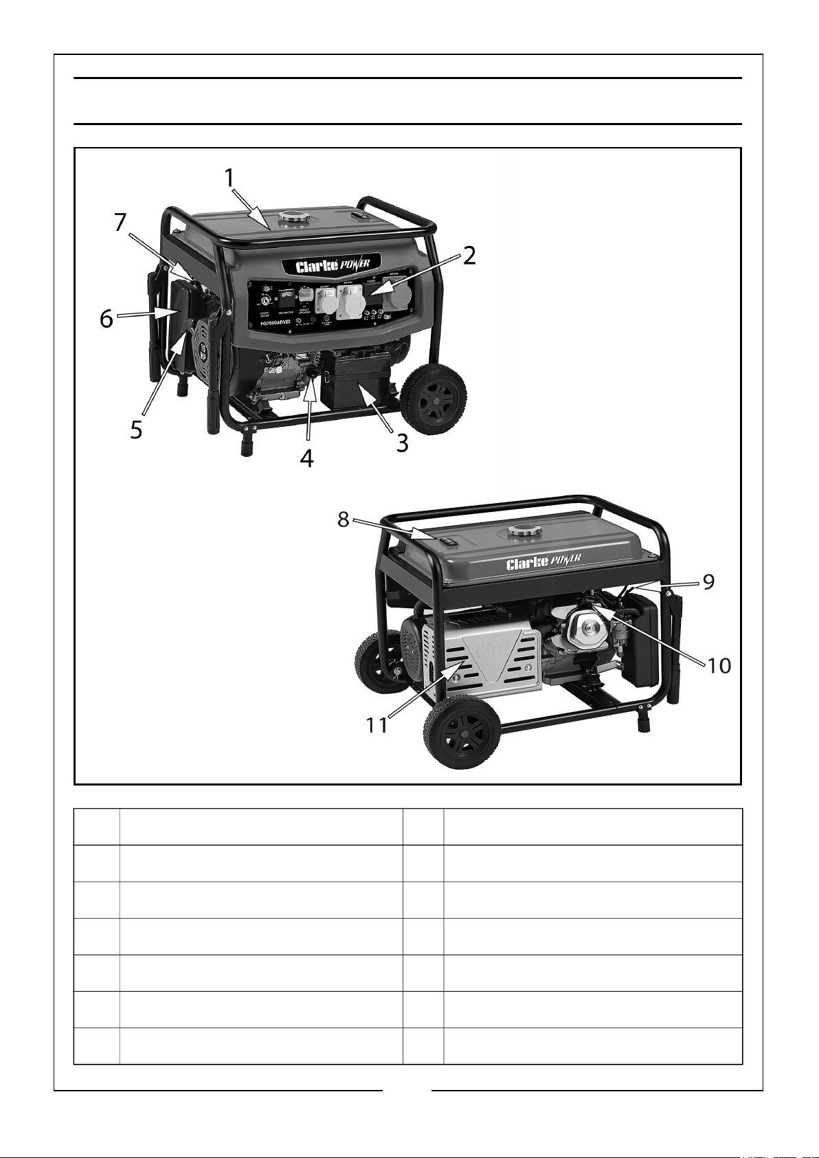
GENERATOR OVERVIEW
NO DESCRIPTION NO DESCRIPTION
1 Fuel Tank 7 Fuel Valve
2 Control Panel 8 Fuel Gauge
3 Battery 9 Choke Lever
4 Oil Filler Cap 10 Spark Plug
5 Starter Handle 11 Muffler (Exhaust)
6 Air Filter
5
Parts & Service: 020 8988 7400 / E-mail: [email protected] or [email protected]
Page 6
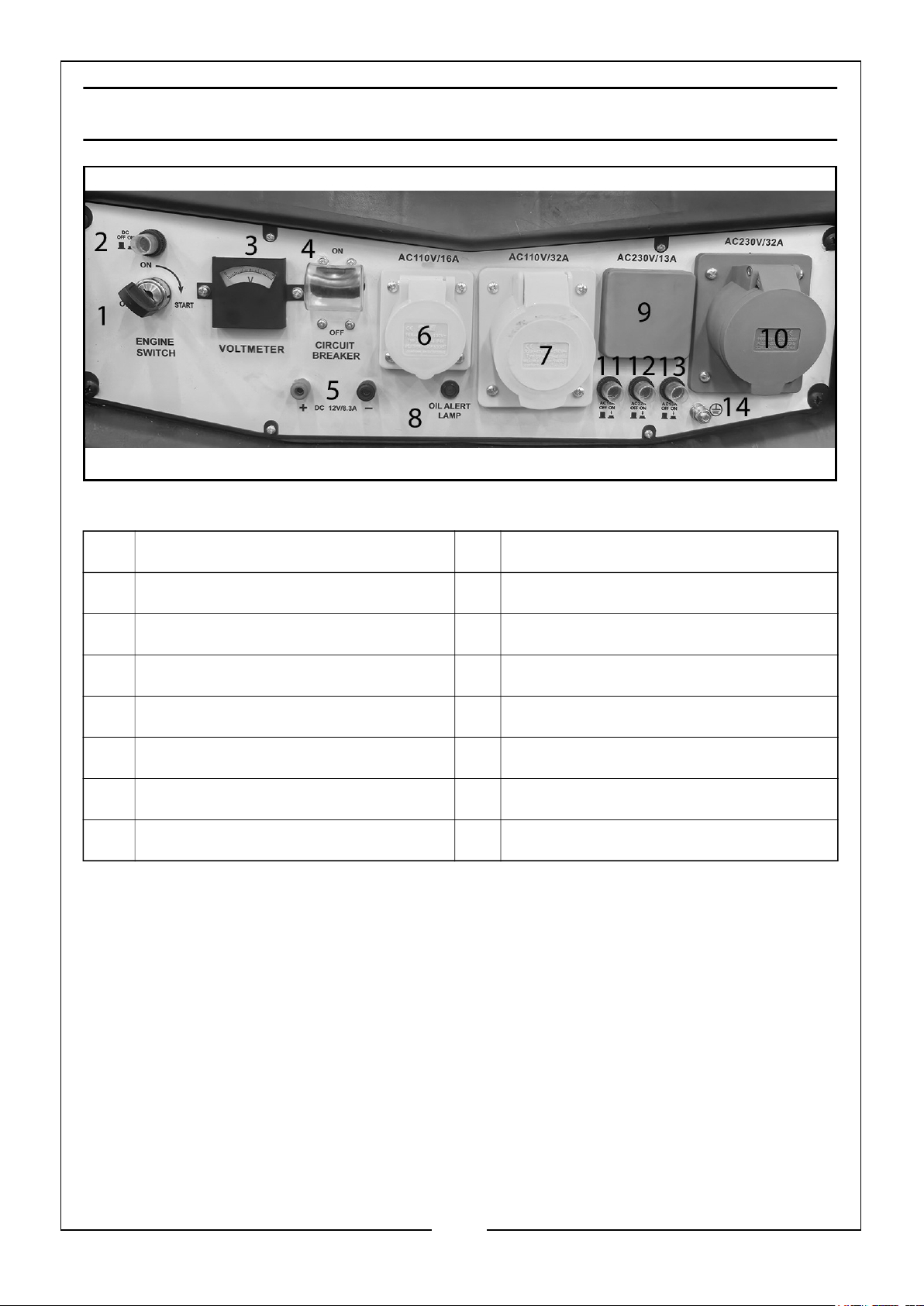
CONTROL PANEL OVERVIEW
NO DESCRIPTION NO DESCRIPTION
1 Engine Key Start 8 Oil Level Alert Light
2 DC 12V 8.3A Circuit Breaker 9 AC 230V 13A Socket
3 Voltmeter 10 AC 230V 32A Socket
4 AC Main Circuit Breaker 11 AC 110V 16A Circuit Breaker
5 DC 12V 8.3A Jumper Terminals 12 AC 110V 32A Circuit Breaker
6 AC 110V 16A Socket 13 AC 230V 13A Circuit Breaker
7 AC 110V 32A Socket 14 Earth Point
6
Parts & Service: 020 8988 7400 / E-mail: [email protected] or [email protected]
Page 7
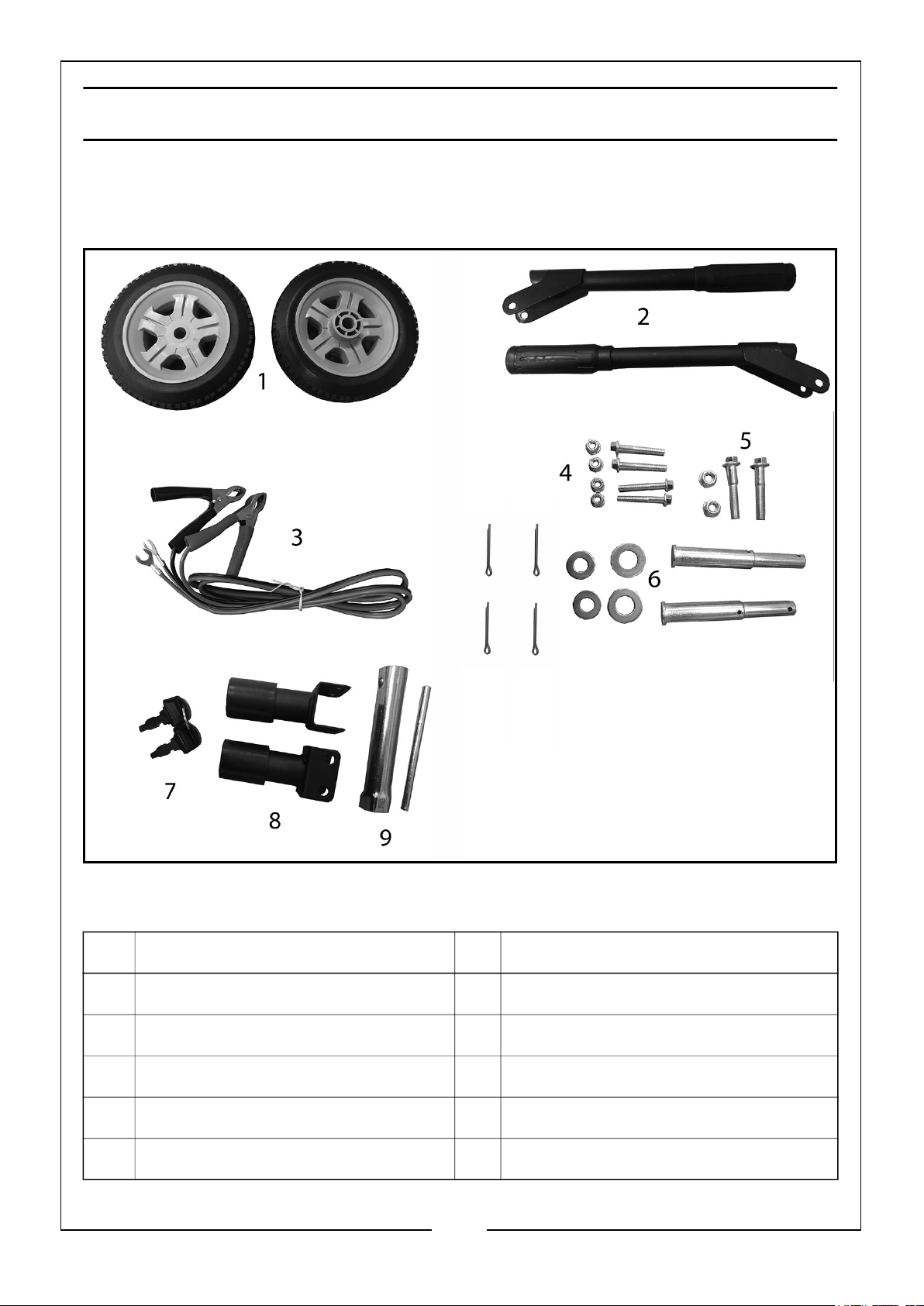
UNPACKING AND ASSEMBLY
Unpack your generator and check to ensure the following items are present. Should
there be any deficiency or damage caused during transit contact your CLARKE dealer
immediately.
NO DESCRIPTION NO DESCRIPTION
1 2 x Wheels 6 2 x Axle, Washers & Split Pins
2 2 x Handles 7 2 x Ignition Keys
3 1 x Crocodile Clip Jump Cable Set 8 2 x Foot Assemblies
4 4 x Foot Assembly Nut and Bolts 9 1 x Spark Plug Box Spanner & Bar
5 2 x Handle Nut and Bolts
7
Parts & Service: 020 8988 7400 / E-mail: [email protected] or [email protected]
Page 8
BEFORE USING THE GENERATOR
Before using your generator check that:
• The generator is in good condition and free from any damage.
• The generator is clean and free from fuel or oil spillage.
• The generator is correctly located for use, see page 3.
• The generator is correctly earthed, see page 10.
• The fuel system is intact and there is no leakage.
NOTE: ALWAYS use a funnel to fill the fuel tank to avoid accidental spillage of
fuel. If fuel is spilled it must be cleaned up before use.
WARNING: ENSURE THERE IS ADEQUATE FUEL IN THE TANK WHEN
USING THE GENERATOR. RUNNING OUT OF FUEL OR STOPPING THE
ENGINE SUDDENLY WITH A LOAD CONNECTED COULD CAUSE
SERIOUS DAMAGE.
WARNING: ALWAYS CHECK THE OIL LEVEL BEFORE STARTING SEE
PAGE 11, FAILURE TO MAINTAIN THE CORRECT OIL LEVEL MAY
SERIOUSLY DAMAGE THE ENGINE.
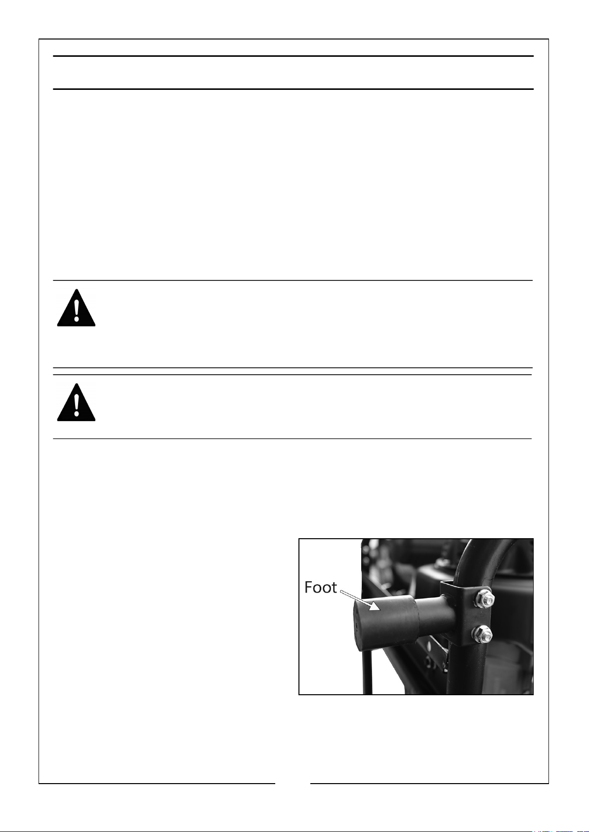
FITTING THE FEET & WHEELS
Due to the weight of the generator it is recommended that 2 people undertake the
assembly.
1. Lay a protective cover on the ground and place the generator on to it.
2. Place the generator on its front end
and attach a foot to the frame using
the 2 x M8 x 50 bolts and 2 x M8
locking nuts, as shown.
3. Repeat this for the second foot.
8
Parts & Service: 020 8988 7400 / E-mail: [email protected] or [email protected]
Page 9
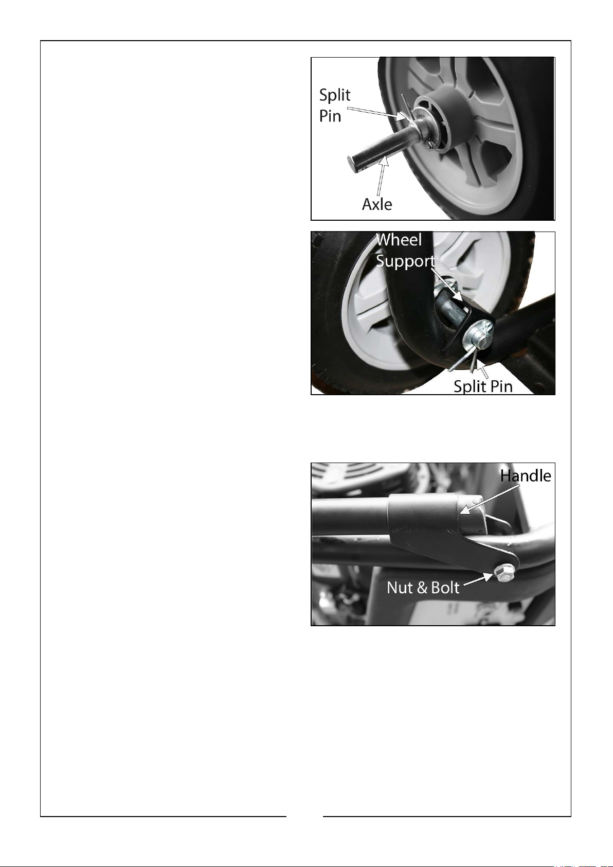
4. Slide a wheel on to an axle and then
one of the large washers and insert a
split pin and fan out to lock in place.
5. Slide this assembly into the wheel
support on the frame.
6. Place the smaller washer onto the
axle and insert the split pin.
7. Fan out the split pin to lock the wheel
assembly in place.
8. Repeat steps 4 - 7 for the second
wheel.
9. Place the generator onto its wheels
and feet.
FITTING THE HANDLES
1. Place the handle into position as
shown.
2. Secure the handle using the large
bolt and locking nut supplied.
3. Repeat steps 1 - 2 for the second
handle.
9
Parts & Service: 020 8988 7400 / E-mail: [email protected] or [email protected]
Page 10
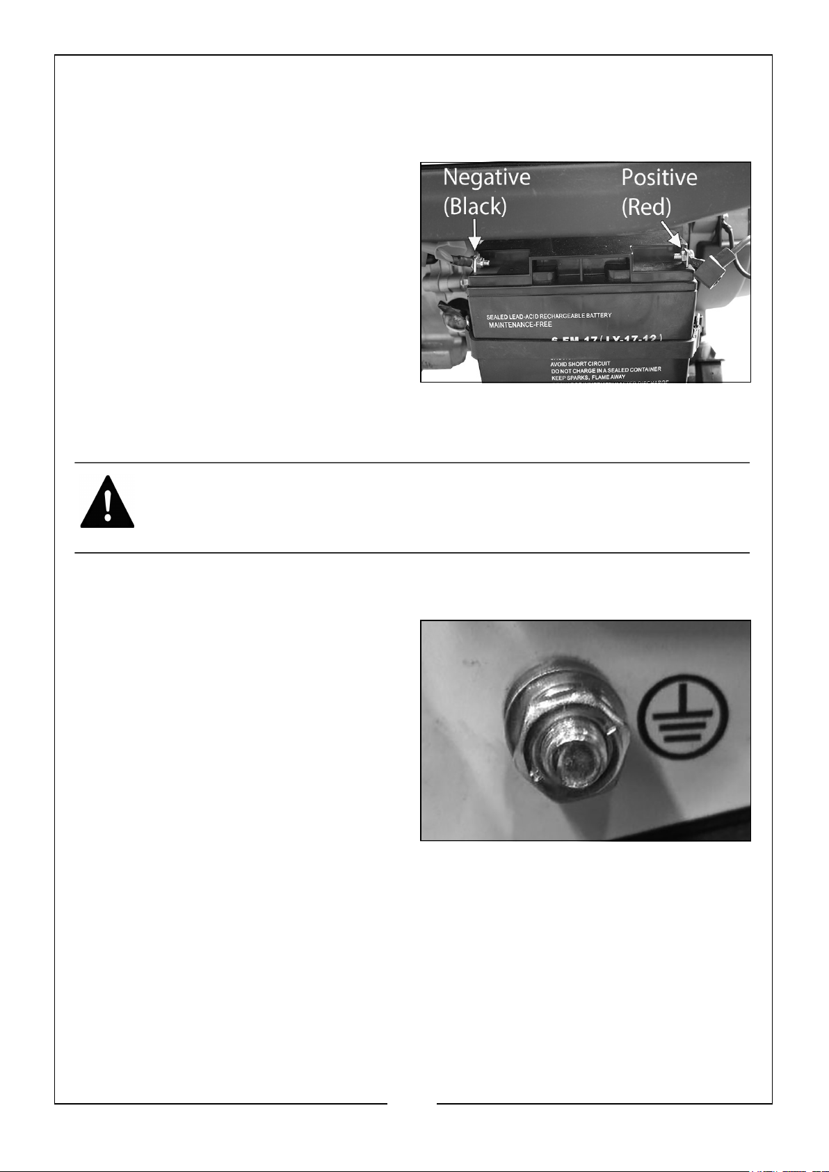
CONNECTING THE BATTERY
For safety reasons, the generator battery is not connected when shipped. Follow these
steps to connect the battery.
1. Connect the negative wire to the
negative terminal on the battery as
shown.
2. Connect the positive wire to the
positive terminal on the battery as
shown.
3. Ensure both terminals are covered by
the plastic covers.
EARTH POINT
WARNING: FAILURE TO PROPERLY GROUND THE GENERATOR
BEFORE USE CAN RESULT IN ELECTROCUTION
Attach a suitable earth lead to a good earthing point - water pipe, ground spike etc.,
whenever you use this generator.
1. Ground the generator by connecting
a suitable grounding wire to the earth
point, as shown, which is located on
the control panel.
2. Connect the other end of the
grounding wire to a copper or brass
grounding rod or suitable grounding
point that is driven into the earth.
10
Parts & Service: 020 8988 7400 / E-mail: [email protected] or [email protected]
Page 11
CHECKING THE ENGINE OIL LEVEL
WARNING: TO CARRY OUT THIS CHECK, PLACE THE GENERATOR ON
LEVEL GROUND WITH THE ENGINE SWITCHED OFF.
WARNING: TAKE CARE NOT TO TOUCH ANY HOT PARTS OF THE
GENERATOR WHEN CHECKING THE OIL LEVEL.
CAUTION: FOR SAFETY SEASONS, THE GENERATOR IS SHIPPED
WITHOUT OIL IN THE ENGINE. DO NOT ATTEMPT TO START THE
ENGINE BEFORE FOLLOWING THE BELOW STEPS TO CHECK AND
INSTALL ENGINE OIL.
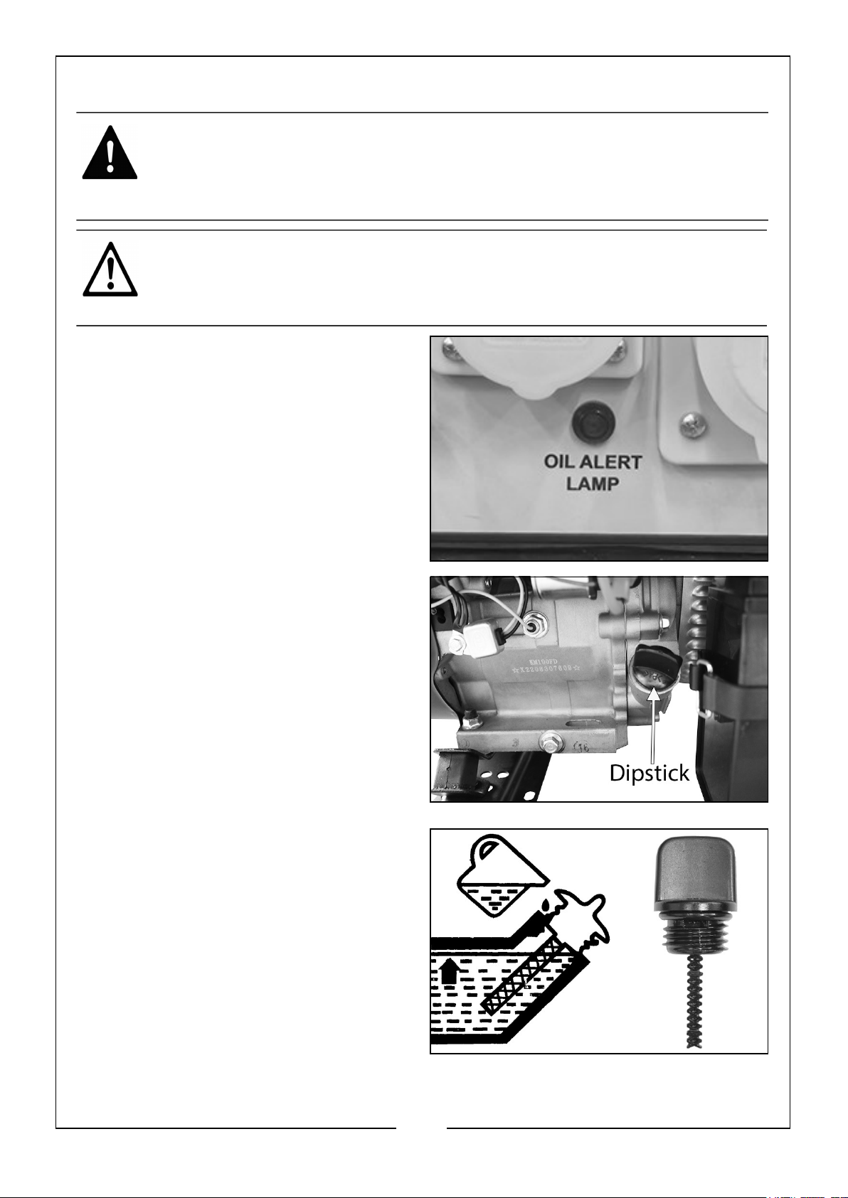
On the control panel is the Oil Level Alert
light. If this light illuminates, then follow
the below instructions.
1. Turn the dipstick anti-clockwise and
remove from the oil fill tube.
2. Wipe the dipstick with a clean cloth.
3. Insert the dipstick back into the oil fill
tube and then remove it again. DO
NOT screw in the oil filler cap/
dipstick when doing this.
4. If the oil level is at or below the ‘L’
mark on the dipstick, using a funnel,
add oil to the crankcase.
• Fill until the oil reaches the
threads in the oil fill tube.
• Oil capacity (See page 21).
• We recommend the use of the
following oil: CLARKE SAE30 Motor
Oil; Part No: 3050852
5. Replace the oil filler cap.
11
Parts & Service: 020 8988 7400 / E-mail: [email protected] or [email protected]
Page 12
CHECKING THE FUEL LEVEL
WARNING: ALWAYS REFUEL IN A WELL VENTILATED AREA AWAY
FROM ANY HEAT SOURCES.
WARNING: ALLOW THE UNIT TO COOL DOWN BEFORE REFUELLING.
WARNING: DO NOT LEAVE FUEL WITHIN THE REACH OF CHILDREN.
For safety seasons, the generator is shipped without petrol in the tank. Follow these
steps to check and install petrol.
RECOMMENDED FUEL
Only use standard unleaded petrol. DO NOT mix oil with the petrol.
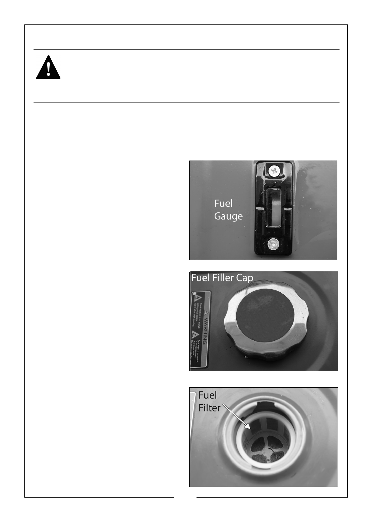
1. Check the fuel level on the fuel
gauge. The fuel gauge will show as
red when you have fuel in the tank
turning white as the fuel level
decreases.
2. To add fuel, open the fuel filler cap.
3. Just inside the fuel tank is a fuel filter
which catches any contaminants as
you refuel.
4. Slowly add fuel to the fuel tank
(maximum safe fill level: 25L)
watching the fuel level gauge as you
do so.
NOTE: DO NOT overfill the fuel tank.
5. Replace the fuel filler cap securely.
12
Parts & Service: 020 8988 7400 / E-mail: [email protected] or [email protected]
Page 13
USING YOUR GENERATOR
STARTING THE ENGINE
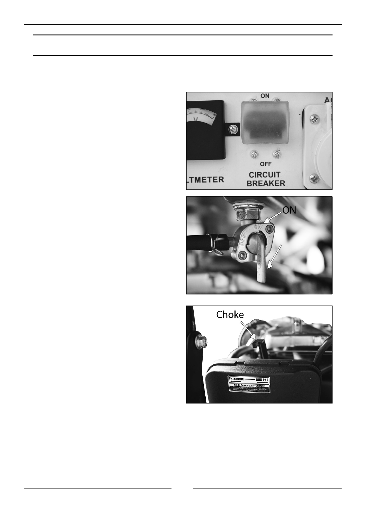
1. Remove all connections from the AC
sockets.
2. Switch the AC Circuit Breaker to the
‘OFF’ position.
3. Set the fuel valve to the ‘ON’ position
as shown.
4. Move the choke lever left to the
‘CHOKE’ position.
NOTE: Move the choke lever right to
the ‘RUN’ position if starting the
engine in hot condition.
13
Parts & Service: 020 8988 7400 / E-mail: [email protected] or [email protected]
Page 14
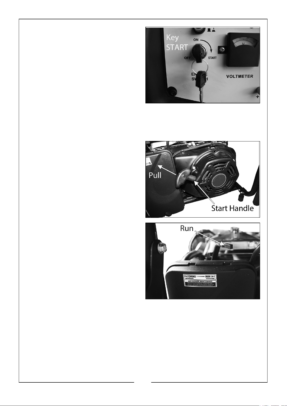
5. Insert the key into the ignition.
6. Turn the key in the ‘START’ position.
NOTE: Once the engine starts the key
will turn back to the ‘ON’ position.
7. Once the engine has warmed up,
move the choke lever right to the
‘RUN’ position.
ALTERNATIVELY
8. Turn the key to the ‘ON’ position.
9. Pull the start handle gently until you
feel some resistance.
10. Then pull the start handle sharply
upwards.
NOTE: You may have to do this more
than once.
NOTE: NEVER let the handle snap
back, as this may cause damage
to the generator and injury.
11. Once the engine has warmed up,
move the choke lever right to the
‘RUN’ position.
14
Parts & Service: 020 8988 7400 / E-mail: [email protected] or [email protected]
Page 15
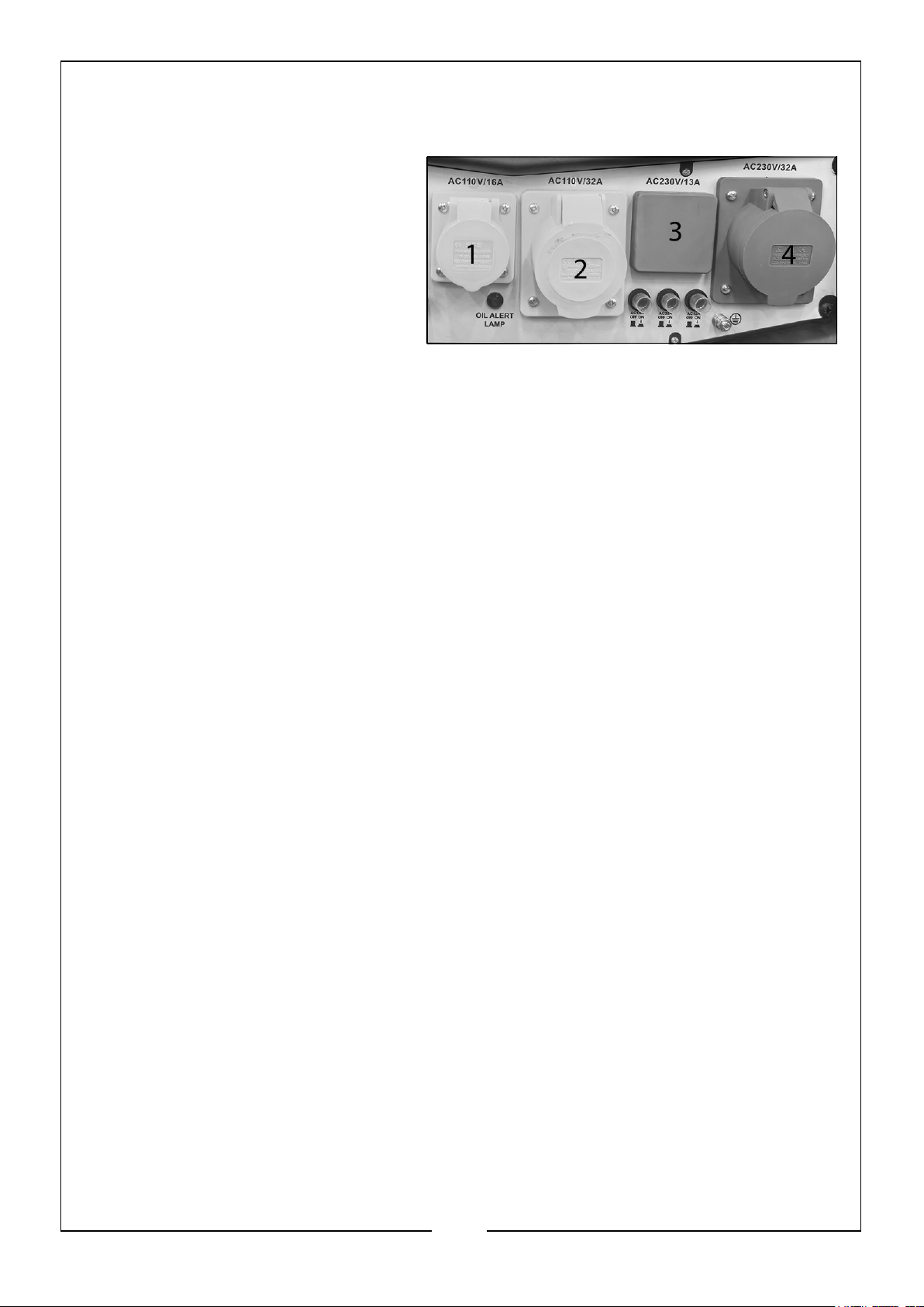
CONNECTING ELECTRICAL DEVICES
The generator can supply both 230V AC and 110V AC.
The sockets are laid out in the
following order: (from left to right):
1. 1 x 16amp 110v (Small Yellow)
2. 1 x 32amp 110v (Large Yellow)
3. 1 x 13amp 230V (Small Black)
4. 1 x 32amp 230V (Large Blue)
Follow the steps below to properly connect your device(s) to the generator.
1. Before connecting electrical devices, allow the generator to run for a few minutes
to stabilise the speed and voltage output.
2. Select the device with the highest wattage and make sure it is turned off. Plug the
device into the generator and then turn the device on. Allow the engine to
stabilise.
3. Repeat step 2 to plug in each additional device. DO NOT attempt to plug in and
start multiple devices at the same time.
GENERATOR CAPACITY
Make sure the generator can supply enough running (rated) and starting (max.) watts
for the items you will power at the same time. Follow these simple steps.
1. Select the items you will power at the same time.
2. Total the running (rated) watts of these items. This is the amount of power the
generator must produce to keep the items running.
3. Estimate how many starting (max.) watts you will need. Starting wattage is the
short burst of power needed to start electric motor driven tools such as a circular
saw or refrigerator. Because not all motors start at the same time, total starting
(max.) watts can be estimated by adding only the items with the highest
additional starting (max.) to the total rated watts.
15
Parts & Service: 020 8988 7400 / E-mail: [email protected] or [email protected]
Page 16
Example Only:
Tool/Appliance Running Watts Additional Starting Watts
Refrigerator 700 1350
Portable Fan 40 120
Laptop 250 250
46 in. Flat Screen TV 190 190
1180 Total Running Watts 1275 Highest Starting Watts
Total Running Watts: 1180
Highest Starting Watts: +1275
Total Starting Watts Needed = 2455
NEVER add more loads than the generator capacity. Take special care to consider surge
loads in generator capacity as previously described.
The chart below serves as a reference only for the estimated wattage requirements of
common electrical devices. however, DO NOT solely reply on this chart, all electronics
and appliances are built differently, ALWAYS check the wattage listed on the electrical
device before consulting this chart:
Tool/Appliance Rated (Running) Watts Surge (Starting) Watts
Hot Plate 2500 0
Saw - Circular 1500 1500
Saw - Mitre 1200 1200
Microwave 1000 0
Well Water Pump 1000 1000
Sump Pump 800 1200
Refrigerator 800 1200
Computer 800 0
Television 500 0
Box Fan 300 600
Light Bulb 75 0
16
Parts & Service: 020 8988 7400 / E-mail: [email protected] or [email protected]
Page 17
JUMPSTARTING A VEHICLE
ALWAYS carry out the following preliminary checks before connecting the generator
to the vehicle battery:
• Switch off the vehicle ignition and ALL ancillary equipment (lighting, radio etc.)
• Ensure the vehicle battery is rated at 12V and not damaged in any way.
• Ensure the area is well ventilated.
• Make sure that the battery terminals are clean and the clamps are firm and
secure.
• If fitted, remove any vehicle battery filler plugs and check the electrolyte
level. If necessary, top up with distilled water.
• Make sure that the generator is OFF.
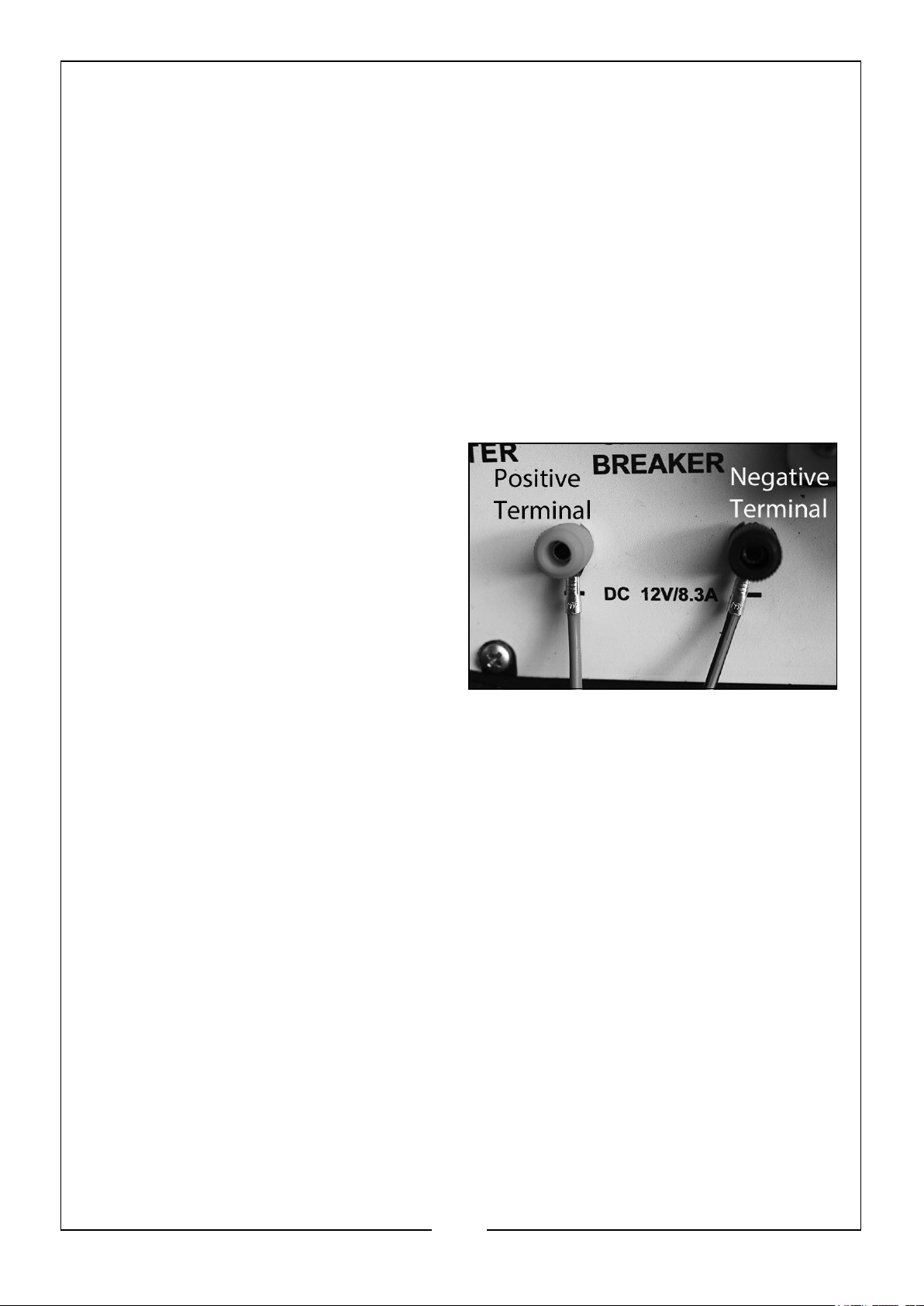
1. Loosen the positive (red) terminal of
the DC 12V/8.3A connections.
2. Take the positive (red, +) ‘C’ clip of
the jump cable and slide it into the
terminal and tighten the terminal.
3. Loosen the negative (black, -)
terminal of the DC 12V/8.3A
connections.
4. Take the negative (black) ‘C’ clip of
the jump cable and slide it into the
terminal and tighten the terminal.
5. Connect the positive (red, +) clamp to the positive (red, +) battery terminal first.
Take care the clamp does not touch any moving parts or fuel lines.
6. Connect the black clamp to the earthed battery terminal, (this is usually the
negative (-ve) terminal and coloured BLACK) or to a suitable earthing point on the
vehicle chassis ensuring the connections are firm and secure.
STARTING THE ENGINE
1. Start the generator, see page 13.
2. Switch or press the vehicle ignition to ‘start’. If the engine does not start, switch
OFF the ignition and wait for at least 30 seconds before trying again.
3. If the vehicle does not start after 3 attempts, investigate any problems with the
vehicle electrical systems.
4. Once the engine is running, switch off the generator, see page 19, disconnect the
earthed (negative, -) clamp FIRST i.e. that connected to the chassis or negative (ve) terminal etc, then disconnect the Positive (+) clamp from the battery terminal.
17
Parts & Service: 020 8988 7400 / E-mail: [email protected] or [email protected]
Page 18
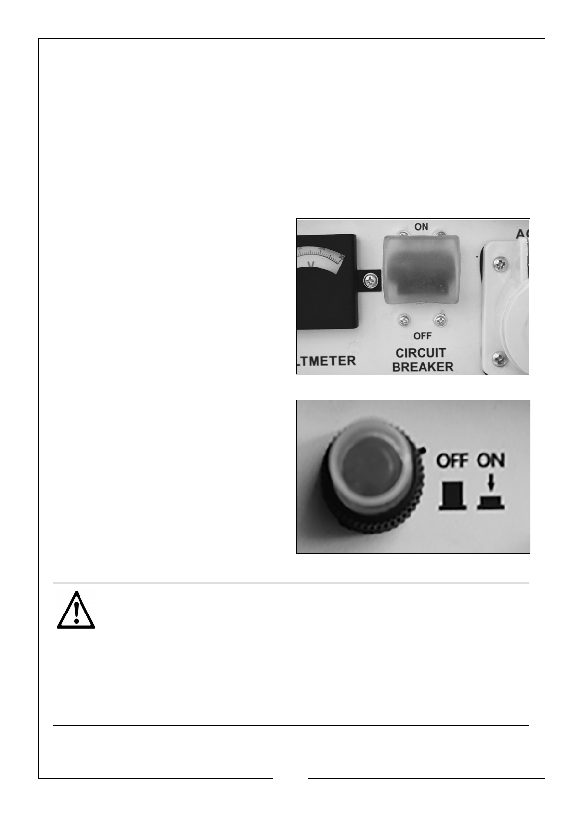
You should remove the connections within 30 seconds of starting the
vehicle.
5. Leave the vehicle engine running for a while to let the alternator recharge the
battery.
NOTE: Take great care not to touch the red positive (+) clamp against the
black negative (-) clamp.
6. Disconnect the ‘C’ clips from the generator.
MAIN AC BREAKER
The Main AC Breaker will activate (switch
to the ‘OFF’ position) if the generator or
circuit is overloaded. If the Main AC
Breaker activates or any of the smaller
individual circuit breakers,
1. Remove any connected devices from
the generator.
2. Wait for a few minutes.
3. Reset the breaker to the ‘ON’
position.
4. Restart the generator.
5. Reconnect the devices to the
generator, making sure you do not
exceed the maximum capacity of the
generator.
CAUTION: MAKE SURE THAT THE APPLIANCE BEING CONNECTED IS
IN GOOD WORKING ORDER, IF IT BEGINS TO ACT ABNORMALLY OR
STOPS SUDDENLY, DISCONNECT IT FROM THE GENERATOR
CAUTION: MAKE SURE THE APPLIANCE DOES NOT EXCEED THE
MAXIMUM RATED LOAD FOR THE GENERATOR.
CAUTION: ANY DEVICE WHICH CONTAINS AN INDUCTIVE LOAD E.G.
DEVICES THAT CONTAIN A MOTOR MAY REQUIRE MORE CURRENT
ON STARTUP.
18
Parts & Service: 020 8988 7400 / E-mail: [email protected] or [email protected]
Page 19
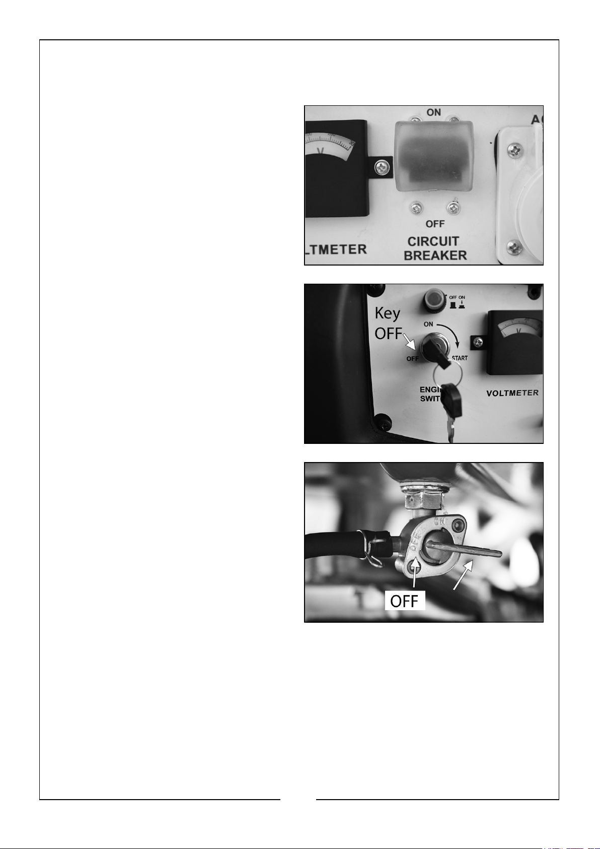
SHUTTING DOWN THE GENERATOR
1. Disconnect all electric devices.
2. Make sure that the AC breaker is set
to the off (down) position.
3. Turn the ignition key to the ‘OFF’
position.
4. Turn the fuel valve to “OFF”.
NOTE: To stop the generator in an
emergency simply turn the ignition
key to the ‘OFF’ position.
19
Parts & Service: 020 8988 7400 / E-mail: [email protected] or [email protected]
Page 20
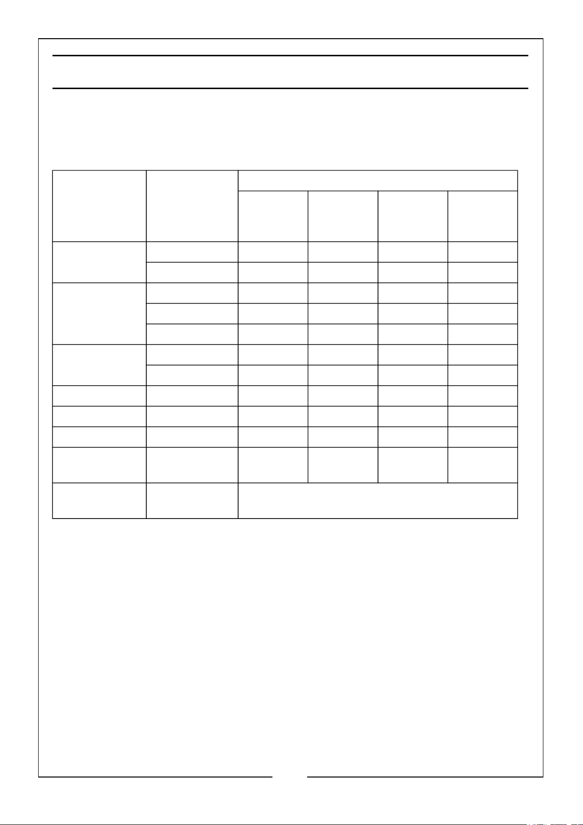
MAINTENANCE
Some adjustments will need to be made periodically to properly maintain the
generator. All service and adjustments should be made at least one time every year. It
is important that the maintenance chart below is followed:
Frequency
Item Action
Engine Oil
(Page 21)
Air Filter
(Page 23)
Spark Plug
(Page 22)
Idling Check - Adjust ***
Valve Clearance Check - Adjust ***
Fuel Tank Clean ***
Fuel Filter
(page 24)
Check Level *
Replace *
Check *
Clean **
Replace *
Clean - Adjust ****
Replace *
Check - Clean *
Each Time
of Use
Every 3
Months or
50 Hrs
Every 6
Months or
100 Hrs
Every Year
or 300 Hrs
Fuel Supply
Line
• ** = Recommended to be performed more often than in the schedule if
operated in a dusty environment.
• *** = Recommended to be performed by a CLARKE authorized dealer.
• **** = Adjust air gap to 0.6 - 0.7 mm.
Parts & Service: 020 8988 7400 / E-mail: [email protected] or [email protected]
Check Every Two Years (Replace if Necessary***)
20
Page 21
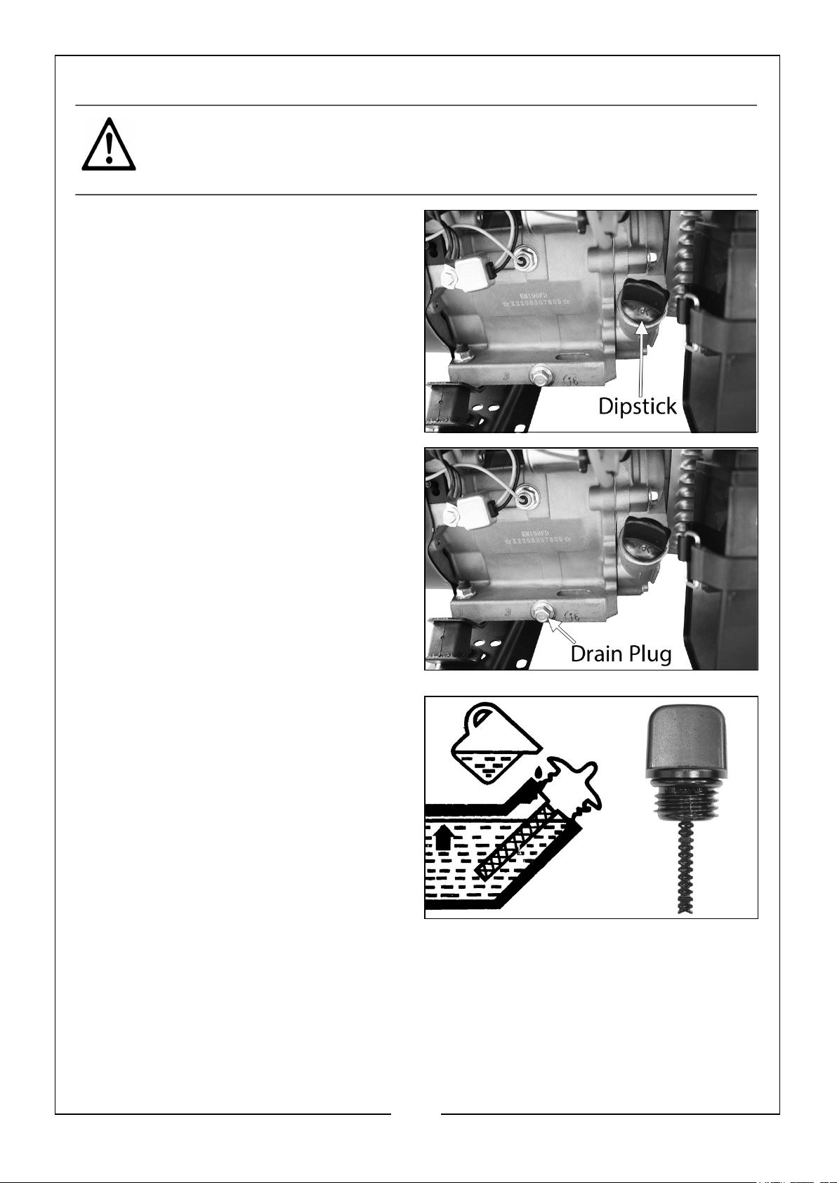
CHANGING THE ENGINE OIL
CAUTION: PROLONGED EXPOSURE TO USED ENGINE OIL IS HARMFUL,
ALWAYS WASH YOUR HANDS THOROUGHLY AFTER HANDLING USED
ENGINE OIL.
1. Unscrew and remove the oil filler
cap/dipstick.
2. Place an oil collection tray under the
drain plug.
3. Unscrew the drain plug and allow the
used engine oil to drain from the
crankcase into the oil collection tray.
NOTE: Drain the engine oil when the
engine is warm, this will ensure
the oil flows out faster.
4. Replace the drain plug.
5. Fill the crankcase with new engine
oil.
• Fill until the oil reaches the
threads in the oil fill tube.
• Oil capacity: 1.1 Litre.
• We recommend the use of the
following oil: CLARKE SAE30 Motor
Oil; Part No: 3050852
6. Replace the oil filler cap/dipstick.
ENVIRONMENTAL PROTECTION
One of the most damaging sources of pollution is oil, DO NOT throw away used
engine oil in with your domestic rubbish or pour it down drains or sinks. Place it in a
leak proof container and take it to your local waste disposal site.
21
Parts & Service: 020 8988 7400 / E-mail: [email protected] or [email protected]
Page 22
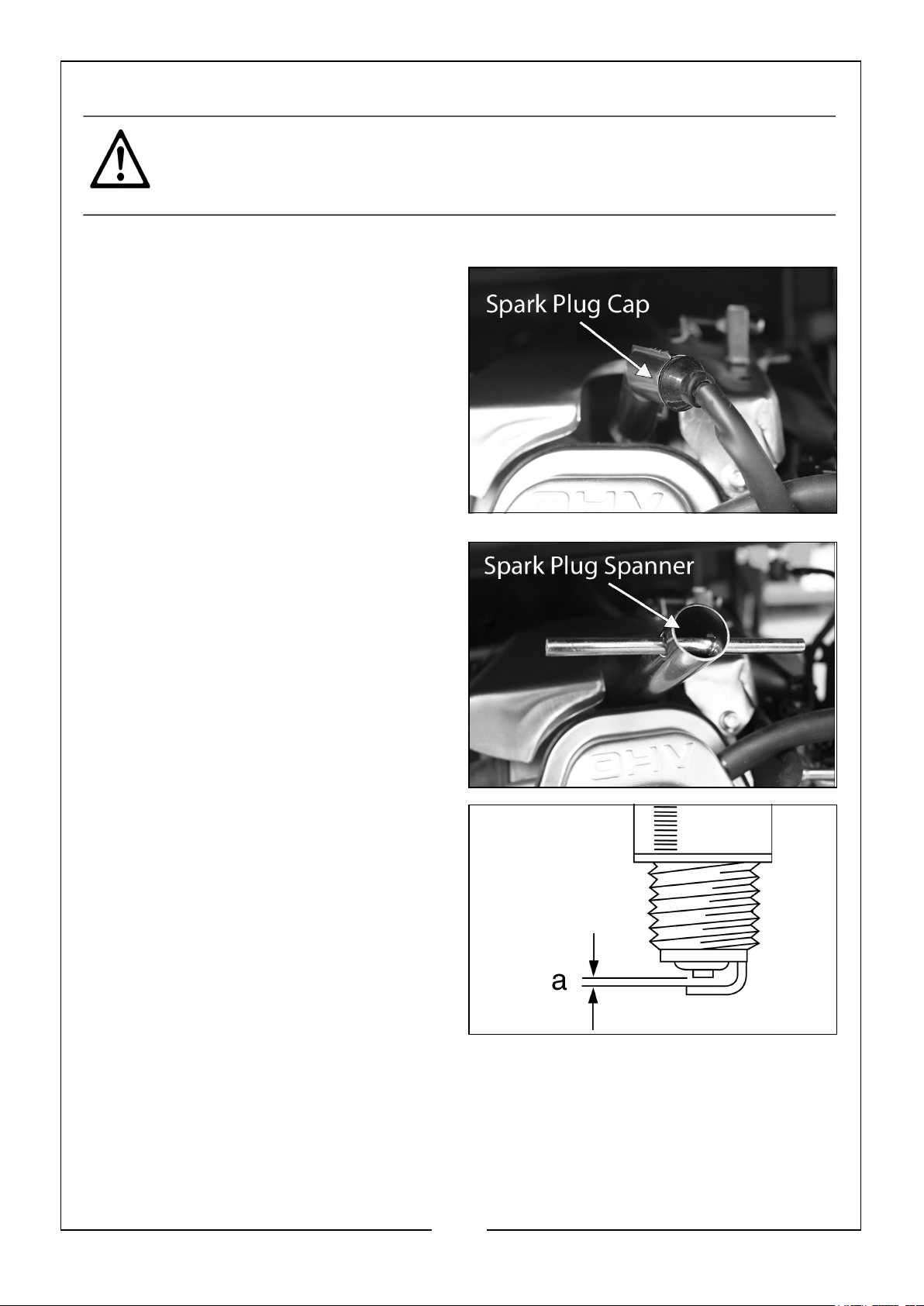
CHANGING THE SPARK PLUG
CAUTION: ALLOW THE ENGINE TO COOL BEFORE REMOVING THE SPARK
PLUG.
1. Remove the side panel bolts and remove the side panel
2. Remove the spark plug cap from the
spark plug.
3. Use the spark plug spanner supplied
to remove the spark plug.
4. Remove any carbon that has
accumulated around the electrode.
5. Check the spark plug gap (a), it
should be between 0.7 and 0.8 mm,
adjust if necessary.
6. Check the overall condition of the
spark plug for erosion or pitting and
replace if necessary.
7. Reinstall the spark plug and replace
the spark plug cap.
22
Parts & Service: 020 8988 7400 / E-mail: [email protected] or [email protected]
Page 23
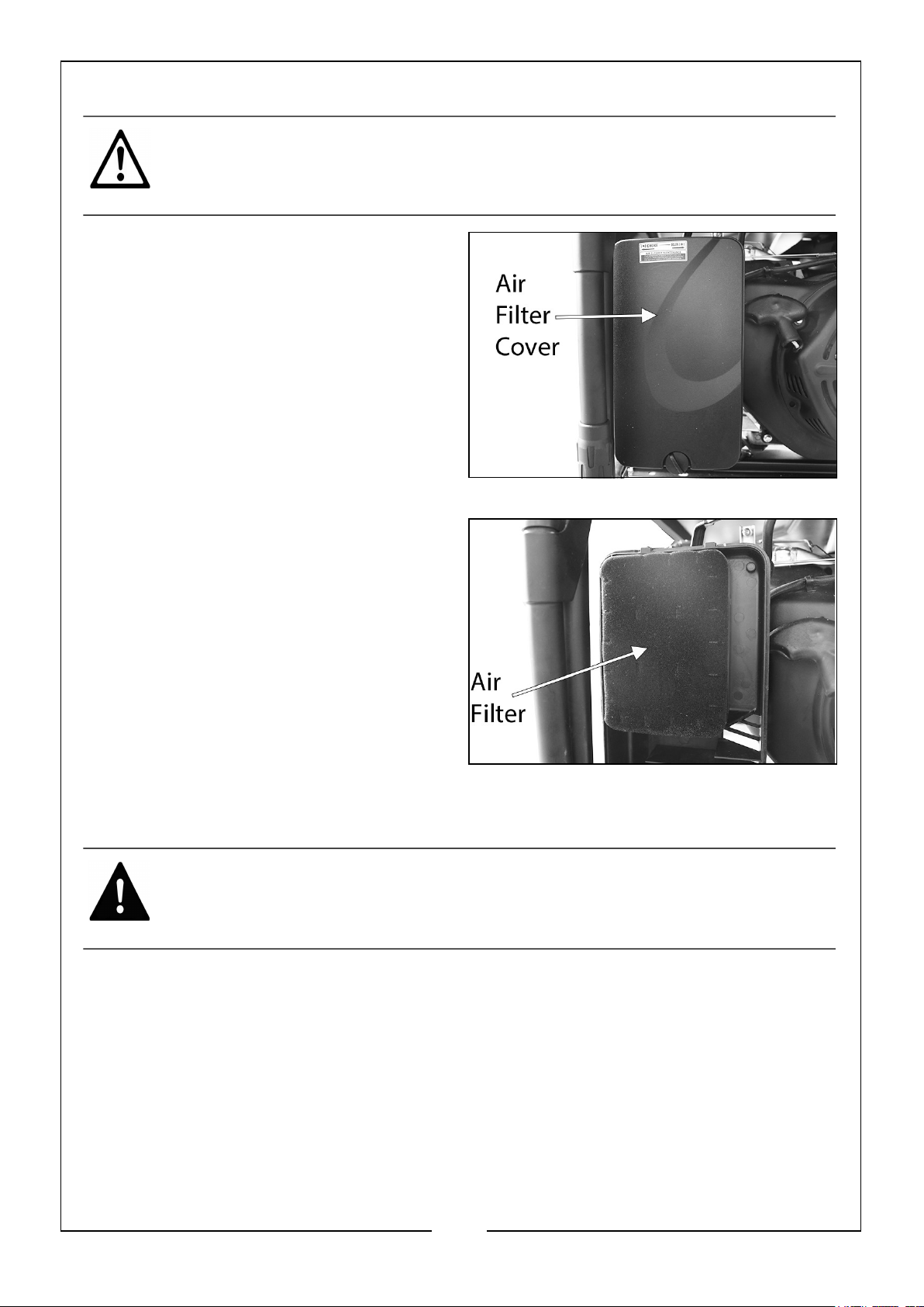
CHECKING THE AIR FILTER
CAUTION: DO NOT USE THE GENERATOR WITHOUT THE AIR FILTER
FITTED, THIS CAN DAMAGE THE GENERATOR.
1. Unclip and remove the air filter cover.
2. Remove the air filter element.
3. Make sure that the air filter is clean
and not damaged.
• If the air filter is damaged contact
CLARKE spare parts department
for a replacement.
• If the filter is dirty, wash in a
solution of warm water and mild
detergent and rinse thoroughly.
Leave the filter to dry completely,
once it is dry immerse in clean engine oil and squeeze to remove excess
oil.
WARNING: DO NOT USE INFLAMMABLE SOLVENTS OR PETROL TO
CLEAN THE AIR FILTER.
4. Replace the filter to its original position and replace the air filter cover.
23
Parts & Service: 020 8988 7400 / E-mail: [email protected] or [email protected]
Page 24
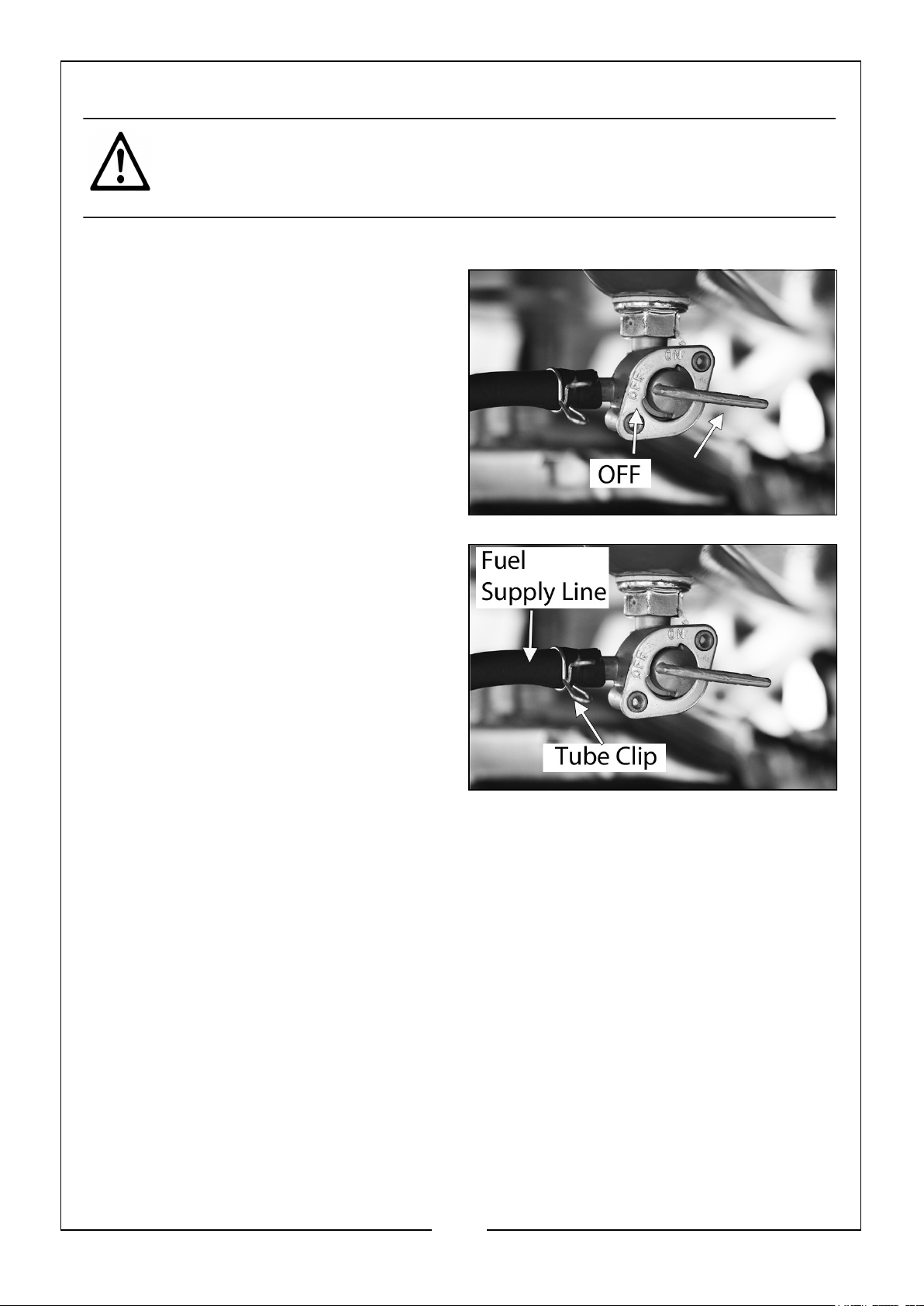
CLEANING/DRAINING THE FUEL TANK & FILTER
CAUTION: ALWAYS CARRY THIS PROCEDURE OUT IN A WELL
VENTILATED AREA AND AWAY FROM ANY NAKED FLAME.
• You will need a length of 7mm external diameter tubing.
1. Set the fuel valve to the ‘OFF’
position.
2. Disconnect the fuel supply line by
pinching the tube clip and pulling the
supply line off the fuel valve.
3. Attach the 7mm external diameter
tubing to the bottom outlet of the
fuel valve.
4. Place an approved petrol storage
container under the tubing and turn
the fuel valve to the ‘ON’ position.
• The fuel in the tank will drain into
the container.
5. Once the fuel tank is empty turn the fuel valve to the ‘OFF’ position and reconnect
the fuel supply line.
CLEAN FUEL TANK FILTER
Just inside the fuel tank is a fuel filter. Check this filter periodically and remove any
contaminants which may have accumulated.
24
Parts & Service: 020 8988 7400 / E-mail: [email protected] or [email protected]
Page 25
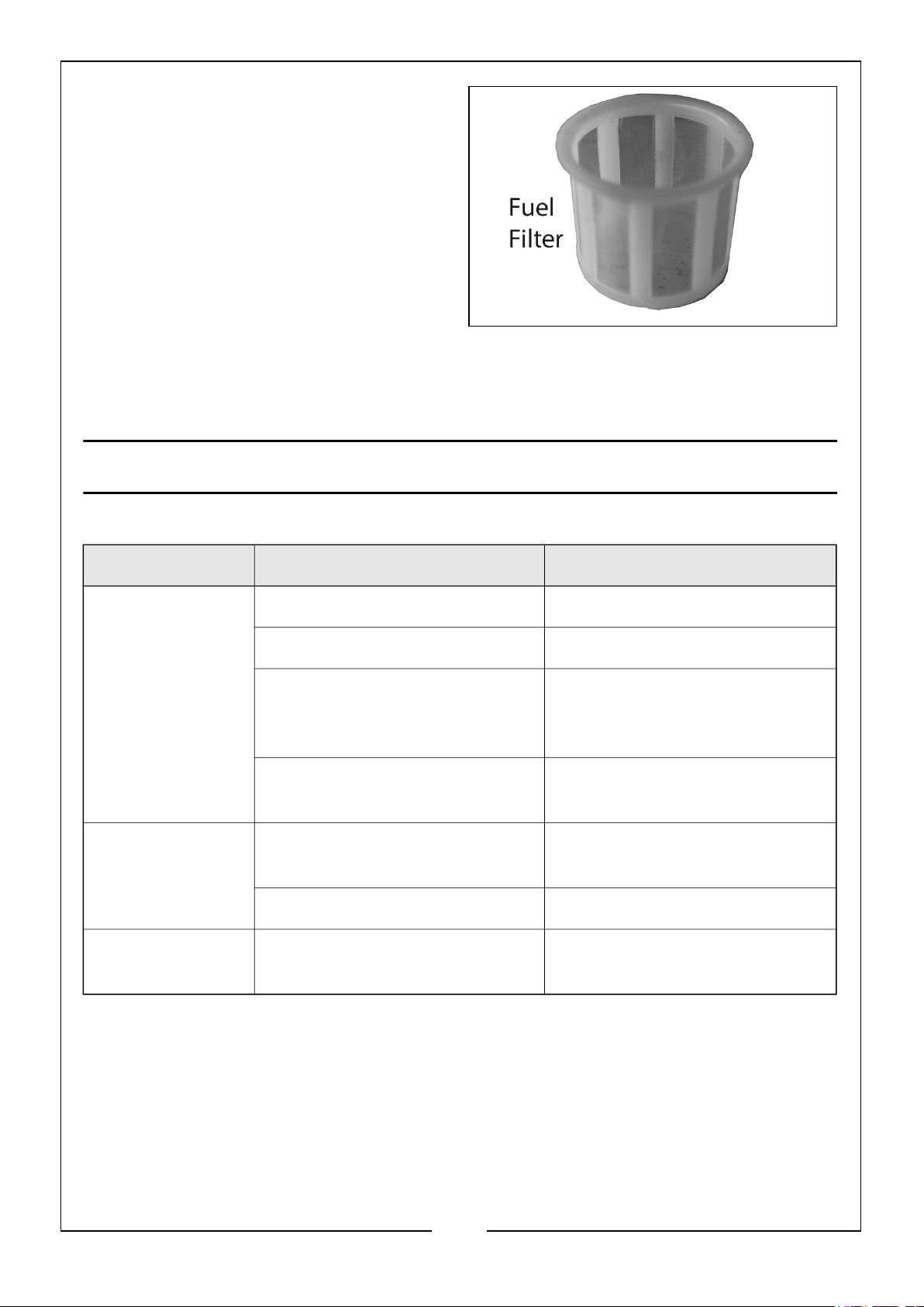
1. Remove the fuel tank cap.
2. Lift out the filter inside.
3. Clean the filter with solvent. If the
filter is damaged, contact CLARKE
Spare Parts department 020 8988 7400 for a replacement.
4. Replace the filter and fuel tank cap.
TROUBLESHOOTING
PROBLEM CAUSE SOLUTION
The generator
fails to start
The generator
fails to generate
electricity
The generator is
difficult to start
Ignition switch is off Set the ignition switch to ‘on’
Not enough oil in the generator Add more oil, see page 11
No fuel Add more fuel, see page 12,
make sure the fuel valve is in
the ‘ON’ position
Spark plug not working correctly Change the spark plug, see
page 22
The device you are trying to
power is faulty
The AC breaker is switched off Switch the AC breaker on
The air filter is dirty Clean the air filter, see page 23
Make sure the device you want
to power is working properly
If this does not solve your problem, please contact the CLARKE service department.
25
Parts & Service: 020 8988 7400 / E-mail: [email protected] or [email protected]
Page 26
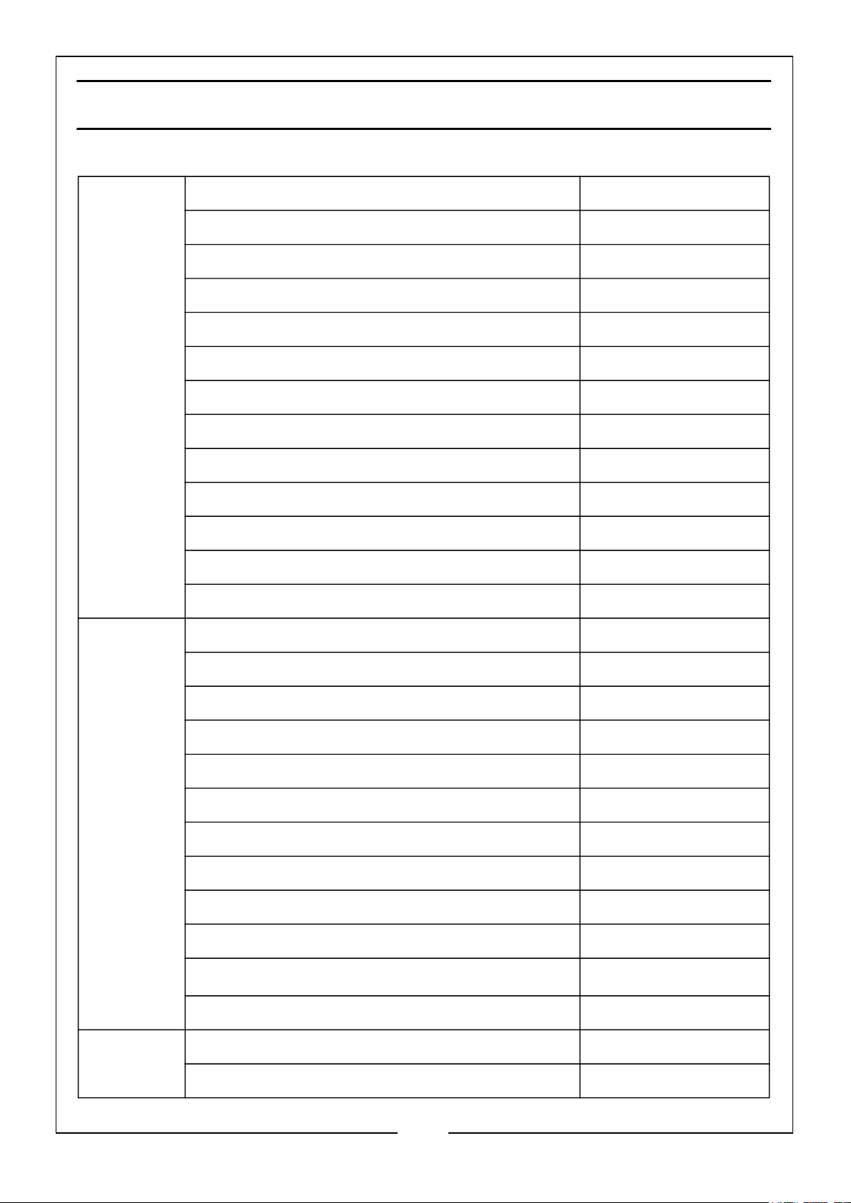
SPECIFICATIONS - PG7500ADVES
Engine Engine Model/Type KM190F/Petrol
Power/Displacement 15HP/420cc
RPM 3600
Ignition type Spark Ignition
Fuel tank capacity (L) 25 (Safe Capacity)
Fuel consumption at 3/4 Load (L/h) 2.8
Maximum run time at 3/4 load (h) Approx. 9
Engine oil capacity (L) 1.1
Emissions (g/kWh) CO, HC+NOx 421, 7.2
Sound pressure level (LpA dB) 76
Sound power level (LwA dB) 96.1
Guaranteed sound power (LwA dB) 97
Uncertainty factor (K dB) 1.02
Generator Rated Frequency (Hz) 50
Rated AC Voltage per socket x 2 (V) 230 (1 x 13A, 1 x 32A)
Rated AC Voltage per socket x 2 (V) 110 (1 x 16A, 1 x 32A)
Rated DC Voltage per socket 1 x USB, 1 x Type C (V) 5
Rated Output Current (A) 54.5/26
Maximum Rated Output Current (A) 32
Max. Rated Output Power (W) 6500
Rated Output Power (W) 6000
Output Type Sine Wave
Starter Type Recoil
Operating Temperatures
IP Rating IP23M
Dimensions Length x Width x Height (mm) 800 x 680 x 620
Unpacked & Unfueled Weight (kg) 82
-5oC to 40oC
26
Parts & Service: 020 8988 7400 / E-mail: [email protected] or [email protected]
Page 27
Page 28
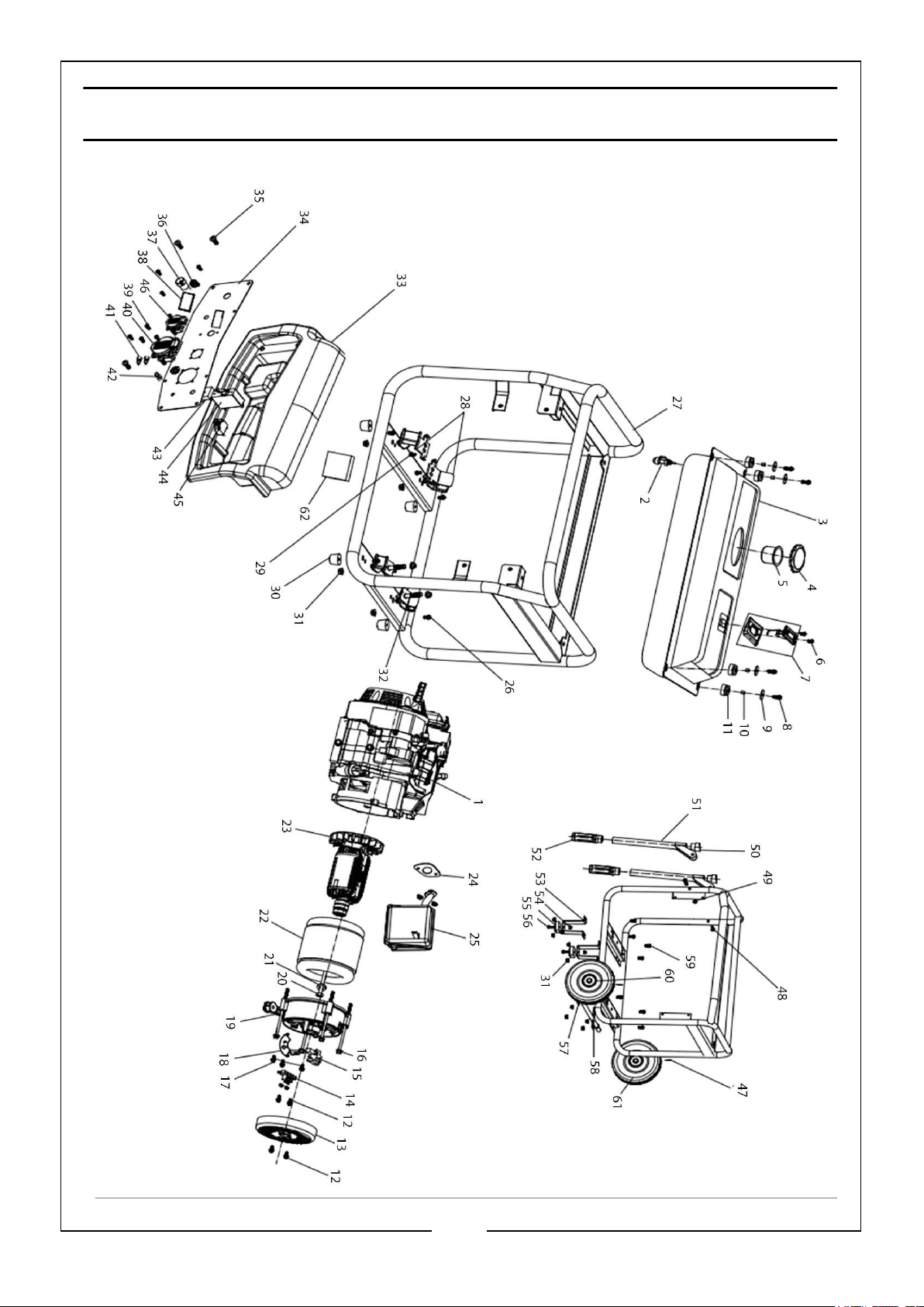
FRAME EXPLODED DIAGRAM
28
Parts & Service: 020 8988 7400 / E-mail: [email protected] or [email protected]
Page 29
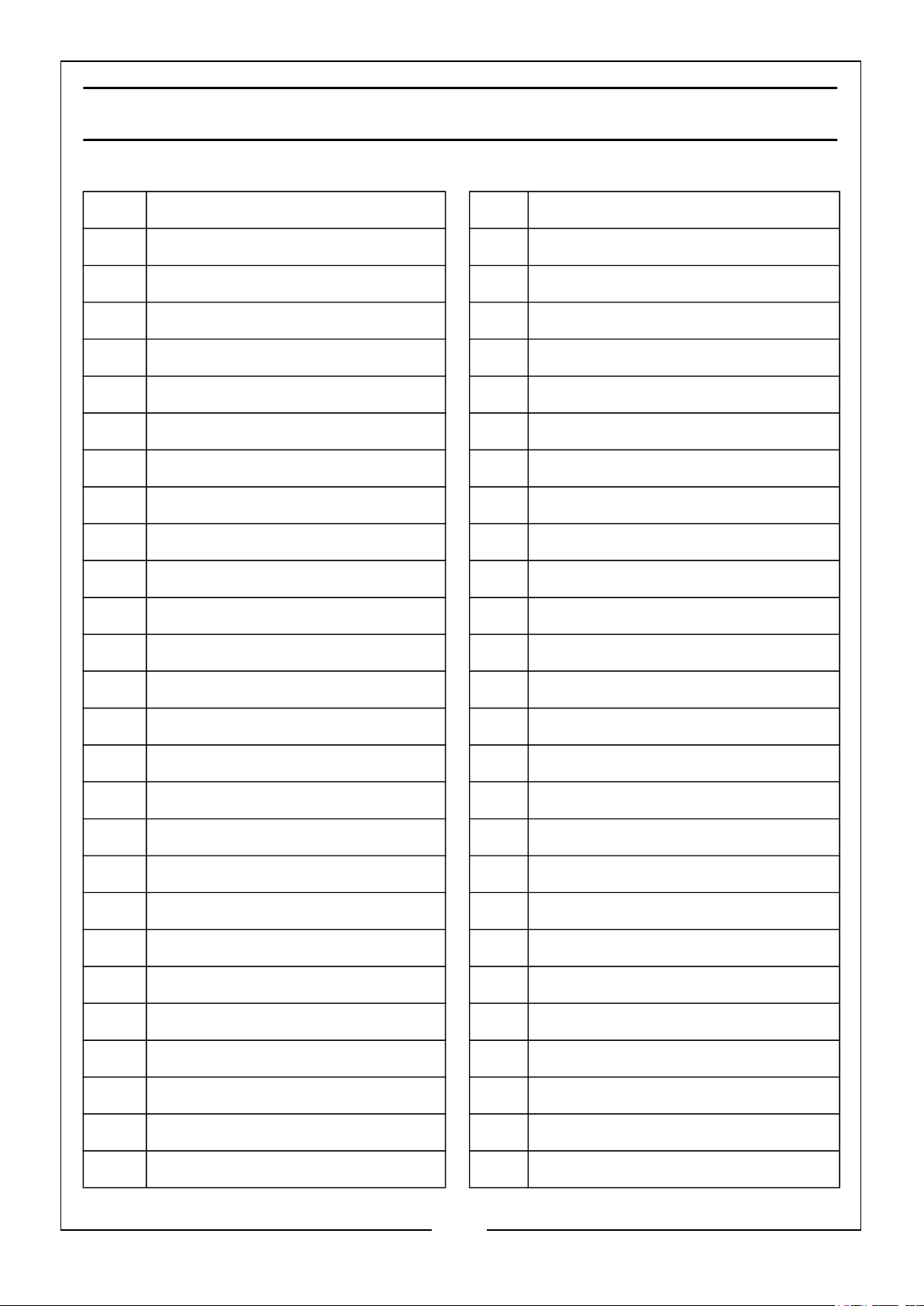
FRAME PARTS LIST
No Description No Description
01 KM190F Engine 27 Main Frame
02 Fuel Control Valve 28 Shockproof Foot (Left) x 2
03 Fuel Tank 29 Bolt x 2
04 Fuel Tank Cap 30 Rubber Foot x 4
05 Fuel Filter 31 Nut x 16
06 Bolt x 2 32 Shockproof Foot (Right) x 2
07 Fuel Meter 33 Control Panel Cover
08 Nut x 4 34 Control Panel
09 Flat Washer x 4 35 Screw
10 Bushing x 4 36 Switch
11 Rubber Gasket x 4 37 Power Light
12 Bolt x 5 38 3 in 1 Digital Display Meter
13 Engine Cover 39 Flat Gasket & Spring Washer x 4
14 Terminal 40 AC230V Socket x 2
15 Carbon Brush 41 DC Terminal
16 Stator Bolt x 4 42 Bolt
17 Bolt x 3 43 Bridge Rectifier
18 Automatic Voltage Regulator 44 Single Pole Circuit Breaker
19 Bracket 45 Circuit Breaker
20 Rotor Bolt 46 AC110V Socket x 2
21 Flat Washer 47 Cotter Pin x 2
22 Stator 48 Bolt x 2
23 Rotor 49 Locknut x 2
24 Gasket (Exhaust Valve) 50 Handle Bracket x 2
25 Muffler 51 Handle Tube x 2
26 Bolt x 4 52 Handle Grip x 2
29
Parts & Service: 020 8988 7400 / E-mail: [email protected] or [email protected]
Page 30

53 Supporting Foot x 2 58 Front Axle
54 Nut x 2 59 Bolt x 8
55 Holder x 2 60 Flat Washer x 2
56 Bolt x 2 61 Front Wheel x 2
57 Axle Clap 62 Accumulator
30
Parts & Service: 020 8988 7400 / E-mail: [email protected] or [email protected]
Page 31
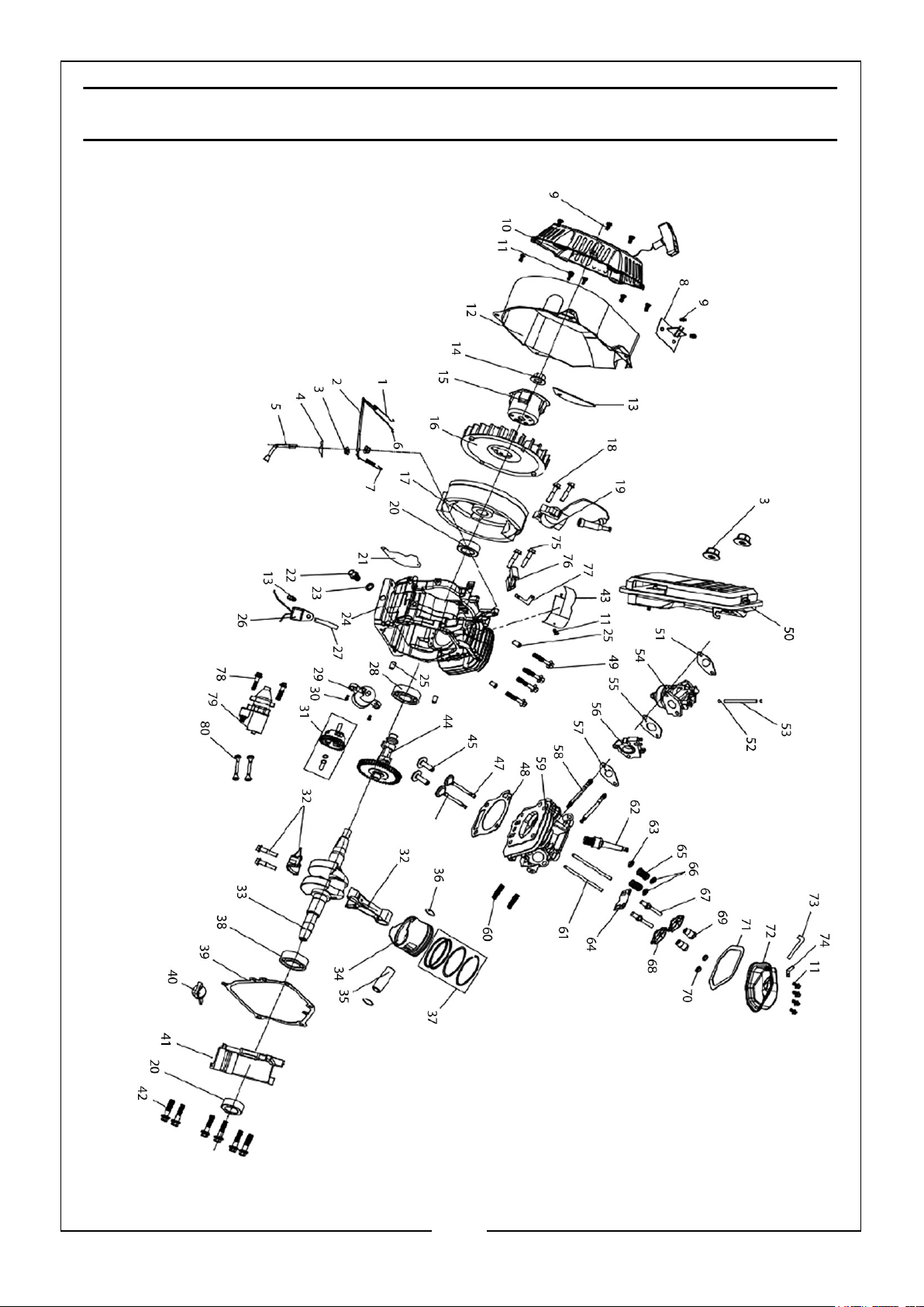
ENGINE EXPLODED DIAGRAM
31
Parts & Service: 020 8988 7400 / E-mail: [email protected] or [email protected]
Page 32
ENGINE PARTS LIST
No Description No Description
01 Reset Spring (Throttle Valve) 27 Wire Clamp
02 Control Assembly 28 Bearing
03 Nut x 4 29 Oil Alert
04 Cotter Pin 30 Bolt
05 Governor Arm 31 Governor Gear Set
06 Governing Pull Rod 32 Connecting Rod
07 Governing Spring 33 Crankshaft
08 Oil Control Set 34 Piston
09 Bolt x 2 35 Piston Pin
10 Recoil Starter Assembly 36 Piston Pin Clip x 2
11 Bolt x 13 37 Piston Ring
12 Outer Vent Casing 38 Bearing
13 Outer Vent Cover 39 Crankshaft Gasket
14 Nut 40 Oil Gauge Set
15 Starting Pulley 41 Crankshaft Cover Set
16 Fly Wheel 42 Bolt x 6
17 Fly Wheel Set 43 Cylinder Air Vent
18 Bolt x 2 44 Camshaft Assembly
19 Ignition Coil 45 Valve Lifter x 2
20 Oil Seal x 2 46 Exhaust Valve
21 Protection Panel (Outer Vent) 47 Intake Valve
22 Bolt 48 Cylinder Head Gasket
23 Gasket Bolt 49 Bolt x 4
24 Crank Case 50 Air Filter
25 Location Pin x 4 51 Air Filter Gasket
26 Oil Protector 52 Fuel Pipe Clamp
32
Parts & Service: 020 8988 7400 / E-mail: [email protected] or [email protected]
Page 33
53 Fuel Pipe 67 Bolt x 2
54 Carburetor 68 Valve Rocker Arm x 2
55 Carburetor Gasket x 2 69 Nut x 2
56 Insulation Board 70 Nut x 2
57 Intake Gasket 71 Cylinder Head Gasket
58 Bolt x 2 72 Cylinder Head Cover
59 Cylinder Head 73 Waste Pipe
60 Bolt x 2 74 High Tension Cable Plate
61 Valve Lifter x 2 75 Bolt x 2
62 Spark Plug 76 Charge Coil
63 Oil Baffle Cover 77 Charging Coil
64 Plate Push Guide 78 Bolt x 2
65 Valve Spring x 2 79 Starting Motor Unit
66 Intake Valve Spring Retainer x 2 80 Battery Cable x 2
33
Parts & Service: 020 8988 7400 / E-mail: [email protected] or [email protected]
Page 34
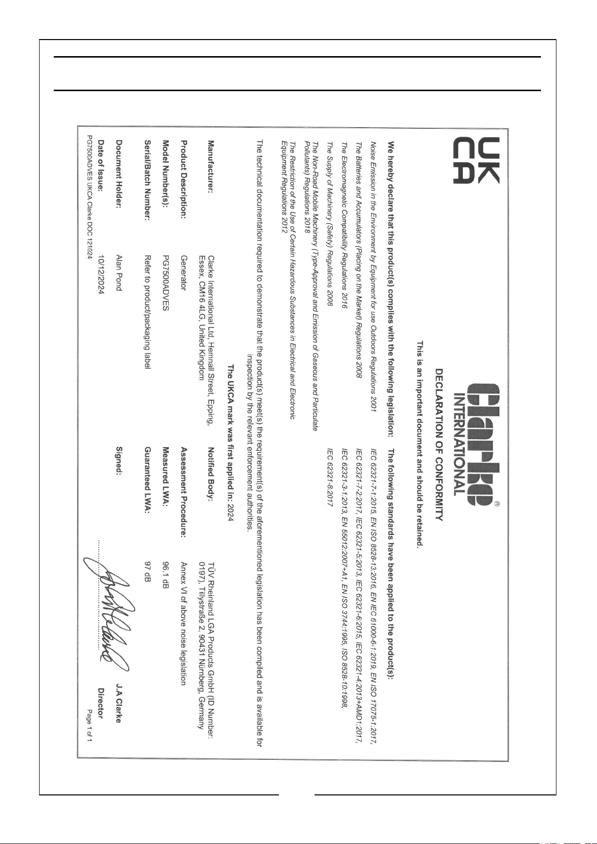
DECLARATION OF CONFORMITY - UKCA
34
Parts & Service: 020 8988 7400 / E-mail: [email protected] or [email protected]
Page 35
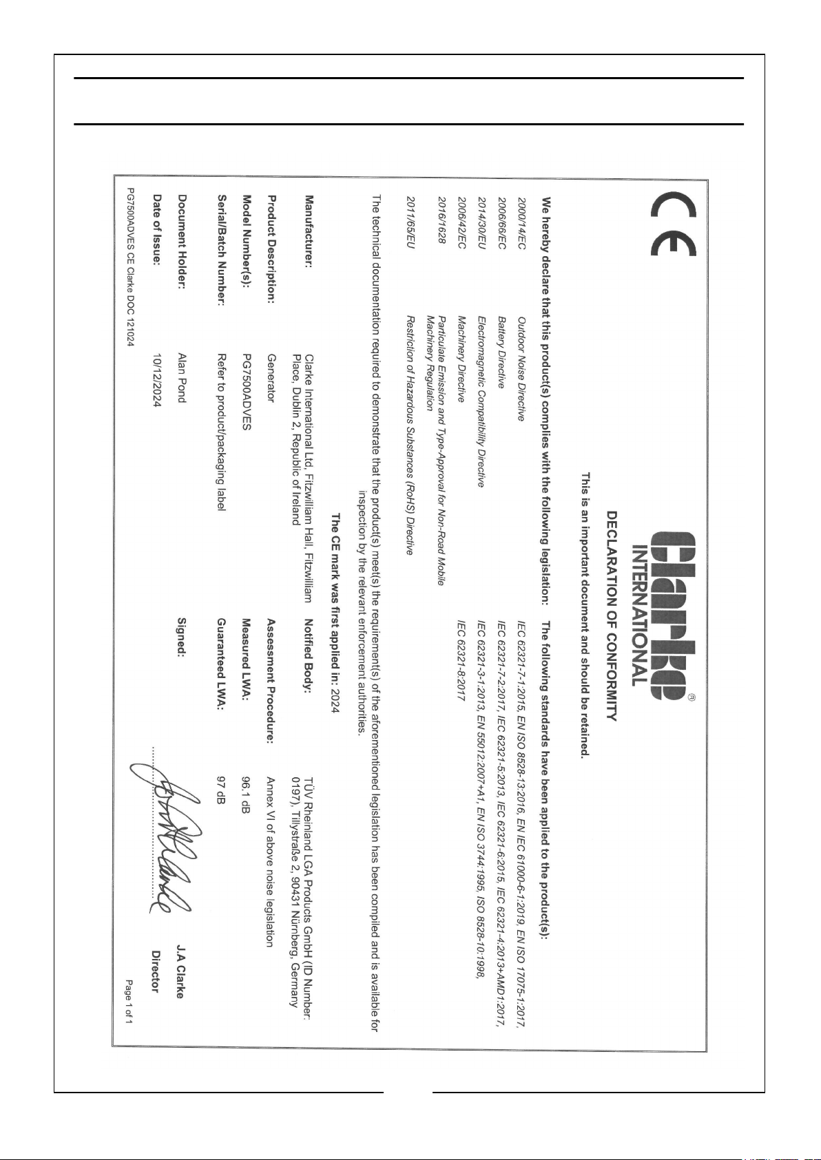
DECLARATION OF CONFORMITY - CE
35
Parts & Service: 020 8988 7400 / E-mail: [email protected] or [email protected]
Page 36

 Loading...