

Page 1
This product is not suitable for primary heating purposes
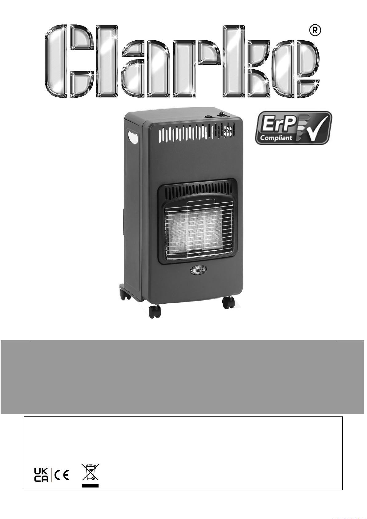
FOLDING MOBILE GAS HEATER
MODEL NO: MGH2
PART NO: 6920028
USER INSTRUCTIONS
ORIGINAL INSTRUCTIONS DL0525 Rev 2
Page 2
INTRODUCTION
Thank you for purchasing this CLARKE Mobile Gas Heater. This portable gas heater is
designed to give safe, efficient and reliable operation and is for use with LPG/Butane
gas only. Gas bottles are not supplied with the unit but are readily available from
builders merchants or gas suppliers.
Before attempting to use this product, please read this manual thoroughly and follow
the instructions carefully. In doing so you will ensure the safety of yourself and that of
others around you, and you can look forward to your purchase giving you long and
satisfactory service.
Read these instructions carefully. DO NOT allow anyone who has not read these
instructions to light, adjust or operate this heater.
GUARANTEE
This product is guaranteed against faulty manufacture for a period of 12 months from
the date of purchase. Please keep your receipt which will be required as proof of
purchase.
This guarantee is invalid if the product is found to have been abused or tampered
with in any way, or not used for the purpose for which it was intended.
Faulty goods should be returned to their place of purchase, no product can be
returned to us without prior permission. This guarantee does not effect your statutory
rights.
ENVIRONMENTAL RECYCLING POLICY
Through purchase of this product, the customer is taking on the obligation
to deal with the WEEE in accordance with the WEEE regulations in relation
to the treatment, recycling & recovery and environmentally sound disposal
of the WEEE.
In effect, this means that this product must not be disposed of with general
household waste. It must be disposed of according to the laws governing Waste
Electrical and Electronic Equipment (WEEE) at a recognised disposal facility.
If disposing of this product or any damaged components, do not dispose of with
general waste. This product contains valuable raw materials. Metal products should
be taken to your local civic amenity site for recycling of metal products.
2
Parts & Service: 020 8988 7400 / E-mail: [email protected] or [email protected]
Page 3
THE FOLLOWING TABLE ADDRESSES THE INFORMATION
REQUIREMENTS OF REG.2024/1103 & ERP COMPLIANCE
Item Symbol Value Unit
Fuel
LPG butane Gaseous G30
Space Heating Emission(*) No
X
62 mg/
kWh
Indirect heating fuctionality: [yes/no] No
Heat Output
At nominal heat output
At minimum heat output (indicative)
Pnom
Pnom
4.2 kW
1.5 kW
Auxiliary electricity consumption
At nominal heat output el
At minimum heat output el
In standby mode el
max
min
SB
N/A kW
N/A kW
N/A kW
Useful Efficiency (NCV)
At nominal heat output
At minimum heat output
nth, nom
nth, nom
100 %
N/A %
Type of heat output/room temperature control (select one)
Single stage heat output, no temperature control Yes
Two or more manual stages, no temperature control No
With mechanical thermostat temp control No
With electronic temperature control No
Electronic temperature control with day timer No
Electronic temperature control with week timer No
Other control options (multiple selections possible)
Room temperature control with presence detection No
Room temperature control with open window detection No
Room temperature control with distance control option No
Room temperature control with adaptive start control No
Room temperature control with working time limitation No
Room temperature control with black bulb sensor No
3
Parts & Service: 020 8988 7400 / E-mail: [email protected] or [email protected]
Page 4

GENERAL SAFETY PRECAUTIONS
1. ALWAYS read and ensure you fully understand the following precautions and the
hazards associated with this type of heater.
2. ALWAYS check for damage before using the heater. Check for broken parts or
anything that may affect its function. Any damage should be properly repaired or
the part replaced. If in doubt, DO NOT use. Consult your local dealer.
3. ALWAYS keep children and animals well away from heater at all times.
4. NEVER carry out any modifications to this product. If experiencing difficulty of
any kind consult your local dealer.
5. NEVER move the heater when it is lit.
6. Use ONLY LPG/Butane gas. Ensure the gas bottle is correctly installed and check
for leaks following replacement, using soapy water. NEVER use a naked flame to
test for leaks.
7. ALWAYS ensure all gas hose and regulator connections are GAS TIGHT, and the
hose is not kinked.
8. NEVER use the heater where gasoline, paint thinner or other highly flammable
vapour or high dust content is present.
9. ONLY use in well ventilated areas. Provide a ventilation opening to fresh, outside
air.ALWAYS ensure that ample ventilation is present if the heater is being lit
following a long period without use.
10. ALWAYS locate the heater on a stable, firm level surface.
11. NEVER cover while in use. Keep all combustibles at least 2m from the front.
12. Use heater in accordance with any applicable fire regulations.
13. NEVER use the heater in high-rise flats, in basements living or sleeping areas, in
vehicles or caravans.
14. NEVER leave a heater unsupervised when lit - someone should always be
responsible for monitoring it. NEVER leave the heater alight while sleeping.
15. NEVER move, handle, replenish gas supply or service the heater when it is hot, or
operating. Turn it off and wait for it to cool down first.
16. Use ONLY the regulator supplied with the heater.
17. ALWAYS ensure that the heater is positioned as described on page 9.
18. NEVER store gas cylinders any closer than 2 m from open drains, gullies or
openings to cellars. LPG is heavier than air and can collect at low levels.
19. This heater will be hot when in operation and due care should be taken.
4
Parts & Service: 020 8988 7400 / E-mail: [email protected] or [email protected]
Page 5

CARBON MONOXIDE HAZARDS
WARNING: LACK OF VENTILATION CAN CAUSE CARBON MONOXIDE
POISONING WHICH CAN BE FATAL.
Carbon Monoxide is a highly toxic, odourless, colourless and tasteless gas, created by
the incomplete combustion of carbon compounds due to a lack of available oxygen in
an enclosed space.
The signs of carbon monoxide poisoning are, headaches, dizziness and/or nausea.
Should anyone show these signs, they must GET FRESH AIR IMMEDIATELY. Turn off
the heater and have it serviced before using again.
Pregnant women, persons with a heart or lung condition, anaemia or under the
influence of alcohol, or those living at high altitudes, are more likely to be effected by
carbon monoxide than others.
CARBON MONOXIDE ALARMS
Due consideration should be given to the dangers of carbon monoxide poisoning
following incomplete combustion in an enclosed space. Carbon monoxide detectors to
BS EN 50291 are available for use in domestic premises.
Where a new appliance is installed in a dwelling, a carbon monoxide alarm should be
provided in the room where the appliance is located.
Carbon monoxide alarms should comply with BS EN 50291:2001 and be powered by a
battery, designed to operate for the working life of the alarm. The alarm should
incorporate a warning device to alert users when its working life is due to pass.
Mains-powered BS EN 50291 Type A carbon monoxide alarms with fixed wiring (not
plug-in types) may be used as alternative applications, provided they are fitted with a
sensor failure warning device.
The carbon monoxide alarm should be located in the same room as the appliance:
• On the ceiling at least 300 mm from any wall or, if located on a wall, as high up
as possible (above any doors and windows) but not within 150 mm of the
ceiling; and
• Between 1m and 3m horizontally from the appliance.
NOTE: Further guidance on the installation of carbon monoxide alarms is
available in BS EN 50292:2002 and from manufacturers instructions.
Provision of an alarm should not be regarded as a substitute for correct
use and regular servicing.
5
Parts & Service: 020 8988 7400 / E-mail: [email protected] or [email protected]
Page 6

FEATURES OF THE MGH2 HEATER
The MGH2 gas heater comprises three groups of components:
GAS SUPPLY COMPONENTS
The gas supply to the machine is by means of a high pressure hose, connected to a
gas cylinder via a pressure regulator.
When the gas valve is opened, gas will flow to the control valve and finally the burner.
The heater can be operated at one of 3 settings using 1,2 or all 3 burner plates.
This heater is designed only to be used with a LPG/Butane gas bottle between 5 and
15kg capacity. Gas bottles are not supplied, but are readily available from builders
merchants or gas suppliers etc.
The minimum surrounding air temperature rating for the heater is min. 5oC maximum +40oC.
IGNITION COMPONENTS
When the ignition button is pressed, a spark is generated which ignites the gas. Heat
from the flame is sensed by a thermocouple which is connected to the Flame Failure
Valve. As the thermocouple heats up, a low voltage is fed to the Safety Cut-Off Valve,
causing the valve to open, so that after a short period, the Control Valve (see
‘Lighting the Heater’ on page 10) may be released, and the pilot flame is established.
SAFETY COMPONENTS
The heater incorporates the following safety devices that will cause it to shut down in
unsafe conditions.
The Flame Failure Valve will shut off the gas if the flame extinguishes for any reason.
When the thermocouple quickly cools down, the gas supply is shut off so that the
heater will shut down automatically.
The Oxygen Depletion Sensor will shut off the gas if the CO
supply to the heater exceeds a pre-set value. The room should therefore be well
ventilated at all times.
NOTE: The Anti-Tilt Switch will turn off the heater if it is tipped over. If this
activates, set the heater upright, check for obvious damage and wait 510 minutes before attempting to re-light the heater. This device may
also operate if the heater Is knocked against or bumped.
concentration in the air
2
6
Parts & Service: 020 8988 7400 / E-mail: [email protected] or [email protected]
Page 7
PREPARATION
When unpacking, check the heater for any damage that may have occurred in transit
and notify your CLARKE dealer immediately should any be apparent.
The heater is supplied with the following fittings;
• 500mm Gas hose
• Jubilee clips
• 21mm snap-fit regulator
• Screws
• Round thumb screws
• Castor wheels & fittings
• Spanner
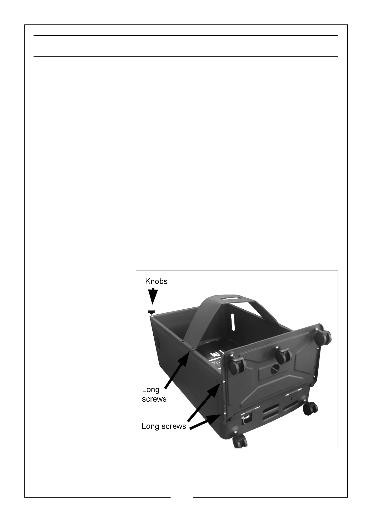
ASSEMBLING THE CABINET/HOUSING
The castor wheels are supplied loose and require fitting.
1. Attach the wheels to the base of the heater and tighten the nuts.
• A spanner is supplied for this purpose.
2. Fold the side panels
into position and align
with the base and top
panels. Secure in
position at the top
and bottom using the
long machine screws
at the base. Add the
hand-knobs at the
top.
3. Fit the gas bottle
retainer to the cabinet
using the short
screws.
The only assembly
required is to connect the
gas supply. DO NOT
attempt to operate the
heater with any gas other
than LPG/Butane. You should have purchased a suitable 15 kg gas bottle for use with
this heater.
7
Parts & Service: 020 8988 7400 / E-mail: [email protected] or [email protected]
Page 8
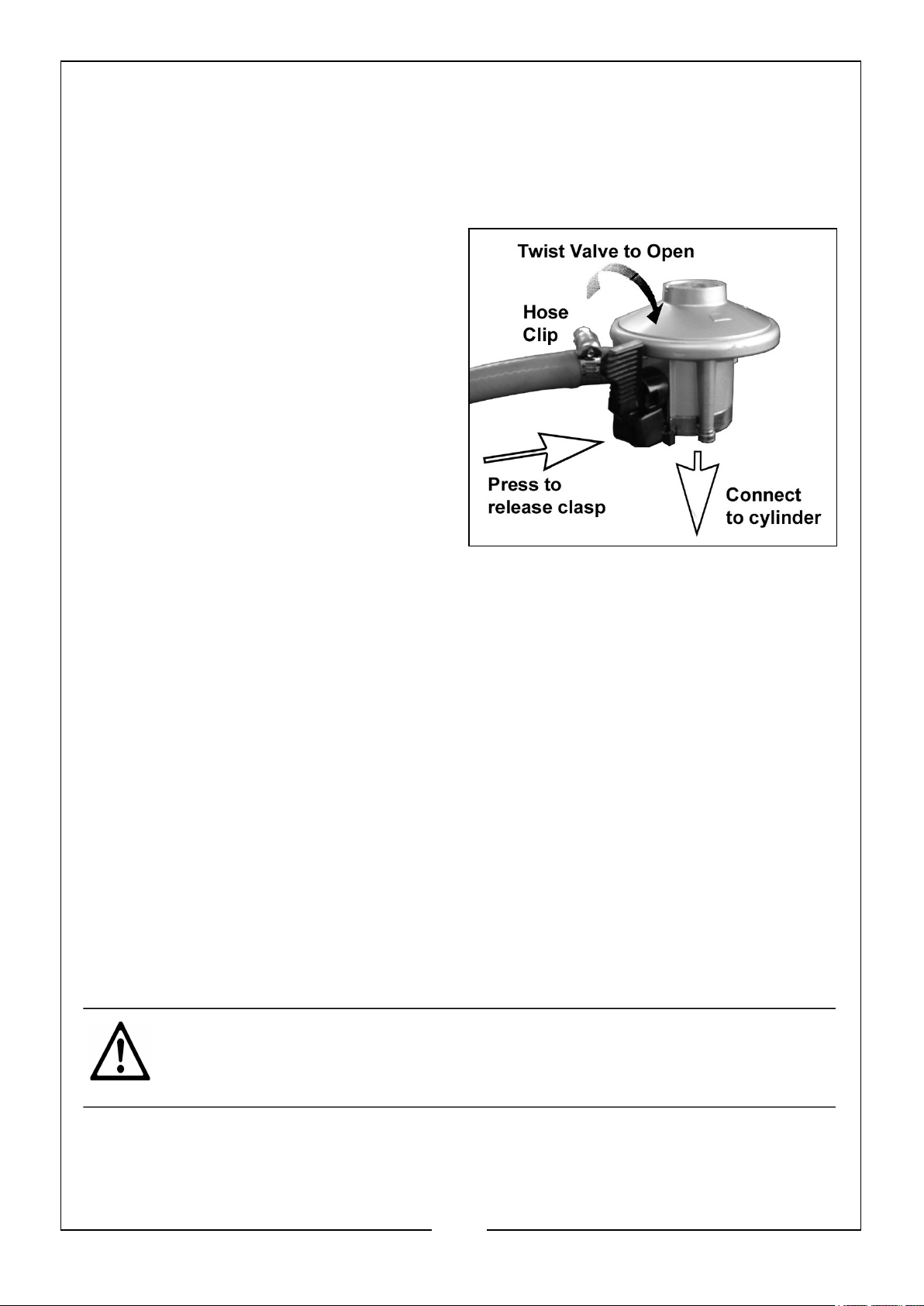
INSTALLING THE GAS BOTTLE
The connection to the gas bottle must be carried out in a well ventilated area using
the regulator and hose assembly supplied with the heater. DO NOT attempt to adjust
this regulator. It has been pre-set at the factory to provide safe and correct
operation.
1. Remove the bottle retainer from the
back of the heater.
2. Secure the gas regulator to the gas
hose with the screwed hose clip
supplied.
3. Place the filled gas bottle in the back
of the heater with the valve outlet
facing outwards.
4. Connect the gas regulator onto the
outlet of the gas bottle using the
integral clasp.
5. When attaching the regulator to the
gas cylinder ensure the bottle outlet is perfectly clean.
• Use compressed air if necessary to blow away any dust or dirt. When
connected, check for leaks as described below.
6. Secure the gas bottle in position with the bottle retainer.
TESTING FOR LEAKS
This must be carried out In a well ventilated area, free from any open flame or other
sources of ignition. With the regulator connected to the cylinder, slowly turn on the
regulator and proceed as follows:
1. Brush all hose connections including pipe connections to the gas valve, regulator
connection to the bottle and gas bottle valve with a 50:50 solution of soap and
water.
2. A stream of bubbles forming Is an indication of a leak. If a leak is found, turn off
the valve on the regulator, disconnect the regulator from the gas bottle and
remove the gas bottle to a cool, outdoor well-ventilated area. Contact your
CLARKE dealer or gas supplier for assistance.
CAUTION: DO NOT USE IF A LEAK IS FOUND. DO NOT USE A NAKED
FLAME FOR TESTING. DO NOT OPERATE ANY ELECTRICAL EQUIPMENT
IN THE PRESENCE OF A GAS LEAK.
3. After leak-testing is satisfactorily carried out and no leaks found, it may be
necessary to twist the cylinder slightly to allow the regulator and hose to fit Inside
the heater casing without kinking the hose.
8
Parts & Service: 020 8988 7400 / E-mail: [email protected] or [email protected]
Page 9
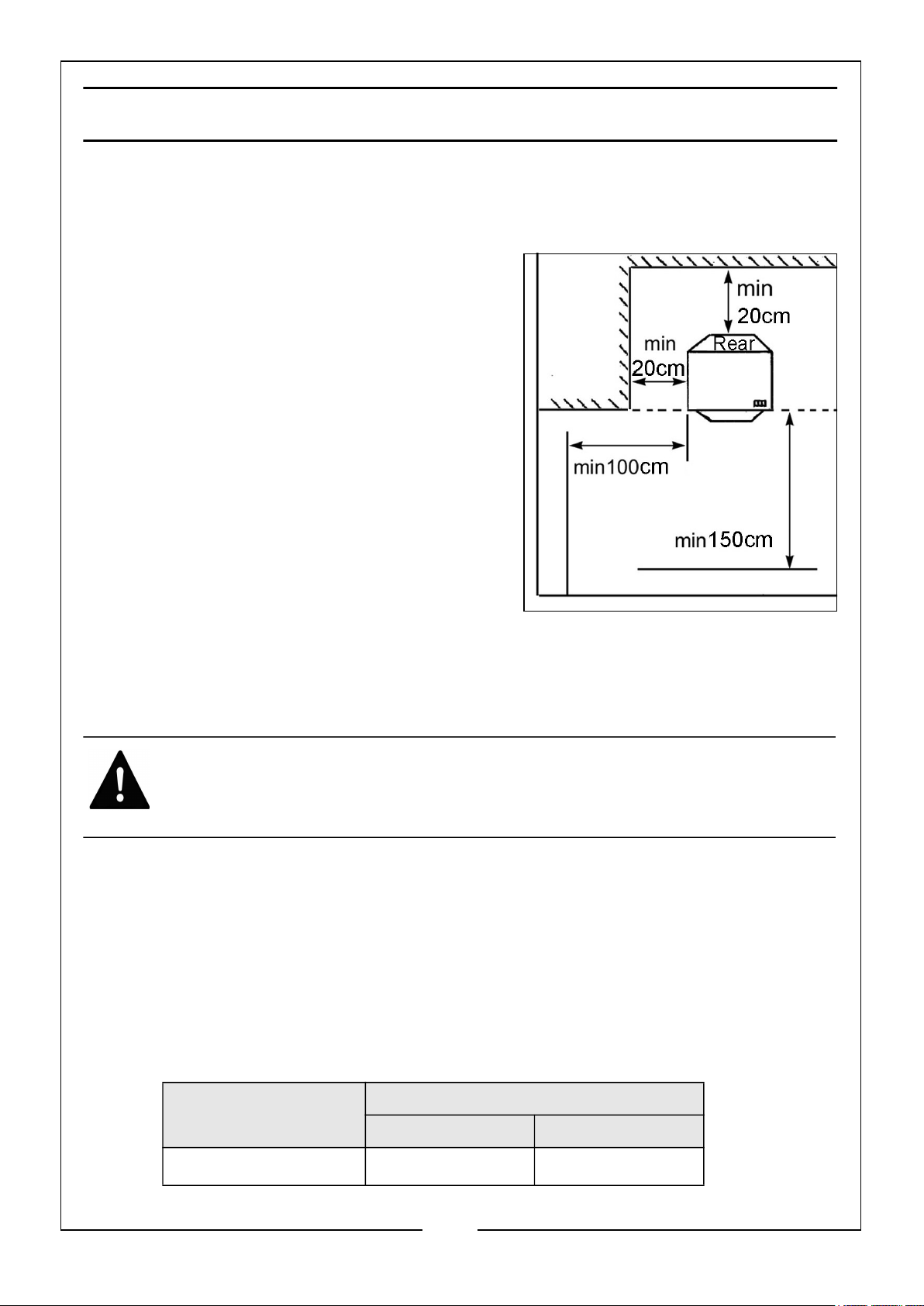
POSITIONING THE HEATER
The heater must be located on a hard, level surface to minimise the risk of accidental
tipping with the gas bottle held by the bottle retainer. DO NOT operate this heater
with the gas bottle in any other than the upright position.
The heater must be located such that it will not
be exposed directly to sources of water. Use of
this heater in a drafty area decreases its
efficiency. If possible, operate the unit in a draft
free area.
MATERIAL CLEARANCES
It is recommended that the heater be
positioned with at least 20cm clearance to the
sides and rear.
However, any household furnishings should be
a safe distance away as they could be
adversely affected by heat.
Always position the heater facing the centre of
the room and positioned as shown in the diagram. Never place objects on, or against
the heater.
VENTILATION
WARNING: IF FRESH, OUTSIDE AIR VENTILATION IS NOT PROVIDED,
CARBON MONOXIDE POISONING COULD OCCUR.
The heater must only be positioned in a room which is well ventilated. DO NOT
operate in a caravan, boat, or any room of less than 40m3 in volume. Ventilation is
essential to reduce the dangers of carbon monoxide poisoning, and from oxygen
depletion.
Adequate ventilation should also considerably reduce the possibility of condensation
occurring and lessen the dangers from the presence of any undetected gas leakage.
The following table shows the smallest sizes of room suitable for each heat setting
and the ventilation which should be provided.
Room size Ventilation
Low Level High Level
3
84 m
Parts & Service: 020 8988 7400 / E-mail: [email protected] or [email protected]
105 m
2
9
105 m
2
Page 10
OPERATION
This heater, including the hose and regulator assembly, must be inspected before
each use and at least annually. If the hose shows evidence of damage or if the hose is
cut, it must be replaced prior to the heater being put into operation. The replacement
hose shall be that specified by CLARKE International.
LIGHTING THE HEATER
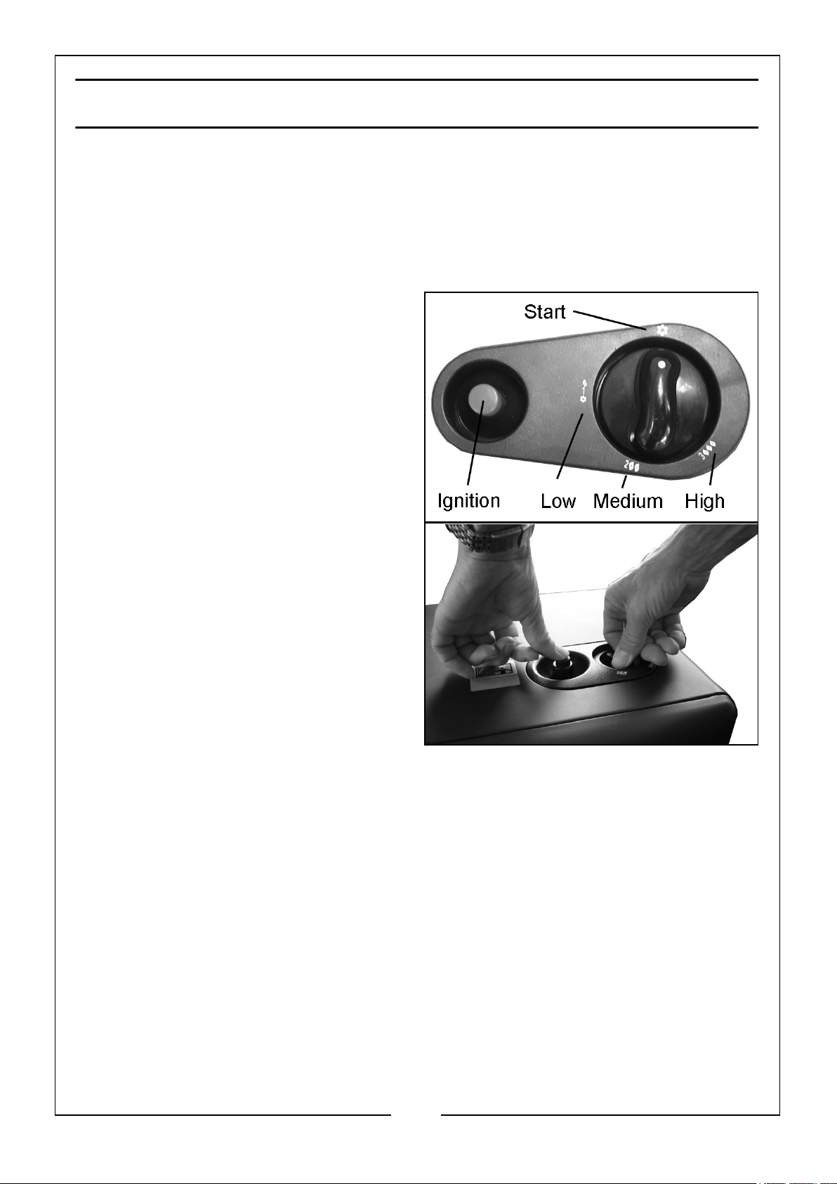
The heater can be regulated to one of
three different heat settings: LOW,
MEDIUM and HIGH. To light the heater:
1. Open the valve on the gas regulator.
2. Press down and turn the control knob
to LOW position.
• DO NOT release the control knob.
3. After 10 seconds press the ignition
button until the pilot light (at the
bottom of the burner) ignites.
4. Continue to hold the control knob
down for 10-15 seconds after
ignition. If the pilot flame goes out
when releasing the button, repeat
the above operation.
NOTE: The first time you use a new
heater, it may be necessary to
hold the control knob down for a longer time in order to purge air from
the system.
Once the heater is alight, turning the control knob to MEDIUM or HIGH will light the
second and third panel automatically.
5. When the heater is in operation, watch the pilot light and check that it is burning
steadily. If it flickers or has a yellow flame, the heater should be checked by your
dealer.
6. Leave the heater burning at the LOW setting for approx 5 minutes before turning
to a higher setting.
The heater can also be started at any of the 1 (LOW), 2 (MEDIUM) or 3 (HIGH)
positions but this is not recommended.
10
Parts & Service: 020 8988 7400 / E-mail: [email protected] or [email protected]
Page 11

CHANGING THE SETTING
1. To select the desired heating level, press the control knob down and rotate until
the knob locks at the desired position (Low, Medium, High). DO NOT operate
between the locked positions.
TURNING THE HEATER OFF
1. Set the control knob to the START position.
2. Turn off the regulator valve on the gas bottle and if placing the heater into
storage, disconnect the bottle.
CHANGING THE BOTTLE
ALWAYS allow the heater to cool down before removing and replacing the bottle.
Never attempt to remove the regulator while the heater is operating.
Disconnect the gas regulator from the cylinder and remove the bottle after releasing
the bottle retainer from the back of the heater.
POSSIBLE FAULTS ON STARTUP
THE HEATER DOESN'T LIGHT
• Check the gas bottle Is full. Removing and tilting the bottle should reveal the
presence of LPG.
• Check the regulator Is properly attached to the bottle and the valve on the
regulator is turned on.
If this happens after the bottle has been changed, it could be:
• The bottle may have been excessively cold. Allow the bottle to reach room
temperature before attempting to start the heater.
• Air in the bottle o hose. Hold the control knob down for a longer period of time
until the pilot and main burner light.
THE HEATER TURNS OFF BY ITSELF
• If the heater turns off by itself after continuous working repeat the lighting
operation.
• If it goes out soon after lighting, check for drafts or for the gas bottle running
out of gas.
• If it goes out after about 30 minutes, it Is an indication that ventilation in the
room is inadequate. If so, the heater may have been shut off by the Oxygen
Depletion Sensor. Open a window or door to ventilate the room and re-ignite.
11
Parts & Service: 020 8988 7400 / E-mail: [email protected] or [email protected]
Page 12

CLEANING AND MAINTENANCE
WARNING: NEVER ATTEMPT TO SERVICE THE HEATER WHILE IT IS
CONNECTED TO THE GAS SUPPLY. ALLOW TO COOL BEFORE
SERVICING.
CLEANING
1. Turn heater off and let cool down before cleaning.
2. Use a damp cloth wrung out in a solution of soapy water to clean the exterior and
bottle storage area of the heater. Use household cleaners on difficult spots.
3. Clean inside heater using compressed air where possible, in which case, eye
protection should be worn. Blow air back and forth along the entire burner face
and ceramic plates until all dust has been dislodged from surface. Take care not to
knock the ceramic plates which can become fragile in use. Use compressed air to
clean the gas outlets.
4. Wipe the heater completely dry before use, ensuring that no water gets into the
burners.
5. Never use abrasive cleaners as they may damage the paint finish.
GENERAL MAINTENANCE
1. Inspect the heater before bringing back into use. Check connections for leaks by
applying a mixture of liquid soap and water to hose connections. Any bubbles
forming show a leak, which must be corrected before use.
2. Regularly check the flexible tubing between the regulator and heater and replace
if cracked. In the event of damage or broken components, replacements should
only be obtained from CLARKE Parts & Service.
3. Have the heater inspected yearly by a qualified service agent.
STORAGE
1. For long term storage, always disconnect the bottle and store the heater in a well
ventilated area away from combustible materials. The bottle is best kept in an
outbuilding and preferably not in a basement or indoors. Cover the heater in its
original packing and keep the unit dry and dust free.
2. With no gas bottle in the heater, the unit can take up less space in storage by
removing the gas bottle retainer and the other fixings described on page 7 and
the panels of the cabinet folded together.
12
Parts & Service: 020 8988 7400 / E-mail: [email protected] or [email protected]
Page 13
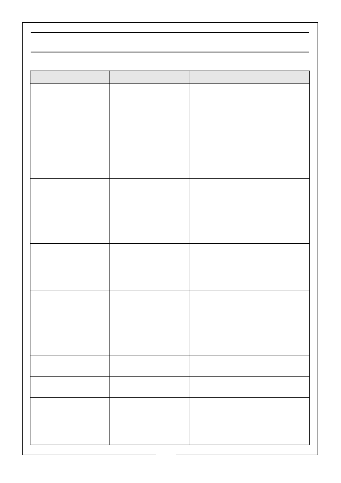
TROUBLESHOOTING
PROBLEM CAUSE REMEDY
Pilot light will not light
automatically.
Pilot light will not light
automatically but
switch & lead are OK
and the pilot will light
using a match.
Heater will not remain
alight when pressure is
released from the
control knob.
After changing to
maximum position with
all 3 burners alight,
one or more appears
below normal intensity.
No spark across
electrode gap.
Incorrect position of
spark in relation to gas
flow.
Electro-magnetic
contact closes while
heater is alight.
a) blocked jets
b) partially blocked
supply tube
c) gas running out.
Request service technician to check
the Piezo-electric switch is
functioning correctly.
Check the electrical lead to the pilot
light is not damaged.
Request service technician to reposition spark plug electrode so that
spark jumps across gas flow.
Request service technician to:
a) ensure that the thermocouple
probe is located in the pilot flame.
b) ensure good connection between
thermocouple and valve.
c) check thermocouple
d) check electromagnetic valve
Request service technician to:
a) remove and clean blocked jet
b) remove the supply tube and
jets and blow through tube.
Difficulty in changing
from Low/Medium/High
Smell of gas Gas leakage from hose or
Pilot flame appears
red.
Smell of burning Missing piece of
Parts & Service: 020 8988 7400 / E-mail: [email protected] or [email protected]
Air draught directed
away from first nozzle.
Position of the pilot flame
incorrect.
tube connection
Dirt in gas nozzle Clean out any dust with
ceramic plate.
13
a) Relocate the heater so that it
is not affected by draughts.
b) Request service technician to
adjust pilot so that flame is
closer to bottom corner of the
second burner as well as first
burner.
Carry out leak test to determine
source as described on page 8.
compressed air
Inspect perimeter of each
ceramic plate and locate
position of missing material.
Repair with fire cement and
leave to set for 24 hours.
Page 14
Patchy combustion
on ceramic plates
Dirty gas outlets. Grime
on ceramic plates
Clean out any dust with
compressed air
SPECIFICATIONS
Model Number MGH2
Dimensions (WxDxH) mm 460 x 420 x 740
Weight 8.2kg
Fuel LPG/Butane G30 Gas
Max Gas Consumption (kg/hr) 305 g/h
Max Rated Input 4.2 kW (14330 btu)
Heat settings High - 4.2 kW
Med - 2.8 kW
Low - 1.5 kW
Operating temperature
Supply pressure 30 mbar
Gas container size 5kg to 15kg (max 32cm dia x 55cm high)
Please note that the details and specifications contained herein are correct at the time
of going to print. However CLARKE International reserve the right to change
specifications at any time without prior notice. Always consult the heater’s data plate.
Min 5oC / Max 40oC
14
Parts & Service: 020 8988 7400 / E-mail: [email protected] or [email protected]
Page 15
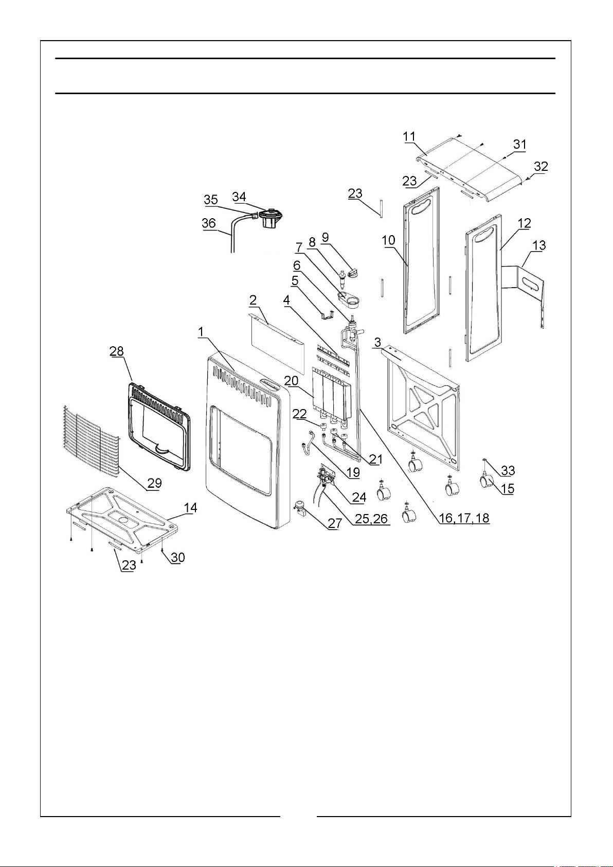
Page 16
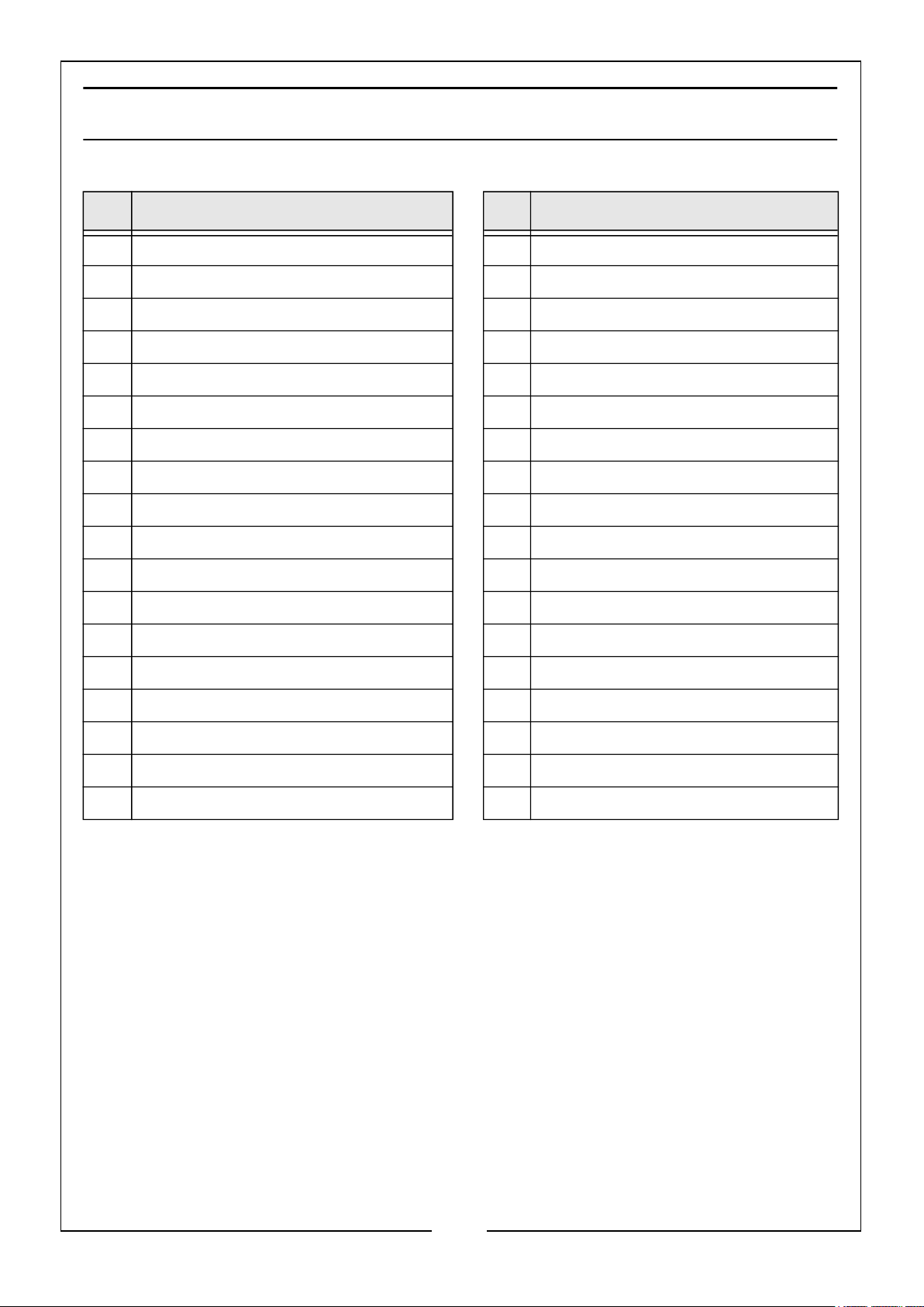
COMPONENT PARTS
No Description No Description
1 Panel 19 ODS gas pipe assembly
2 Lower thermal baffle 20 Burner assembly
3 Top thermal baffle 21 Nozzle assembly
4 Ceramic tile holder 22 Nozzle assembly
5 Base bracket 23 Hinge pin
6 Gas valve 24 ODS pilot
7 Switch mounting 25 Ignition cable
8 Igniter 26 Thermocouple cable
9 Control knob 27 Anti-tilt switch
10 Left side panel 28 Front panel
11 Top panel 29 Front grill
12 Right side panel 30 Screw
13 Cylinder holder 31 Screw
14 Bottom panel 32 Thumb screw
15 Caster wheel 33 Nut
16 Gas pipe assembly (burner 1) 34 Gas regulator valve
17 Gas pipe assembly (burner 2) 35 Hose clip
18 Gas pipe assembly (burner 3) 36 Connecting hose
16
Parts & Service: 020 8988 7400 / E-mail: [email protected] or [email protected]
Page 17
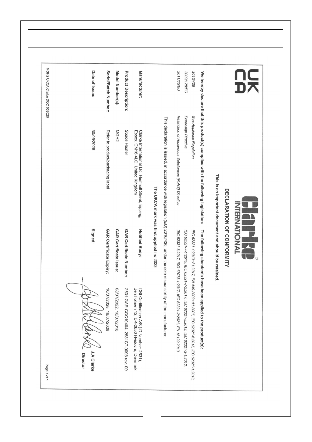
DECLARATION OF CONFORMITY - UKCA
17
Parts & Service: 020 8988 7400 / E-mail: [email protected] or [email protected]
Page 18
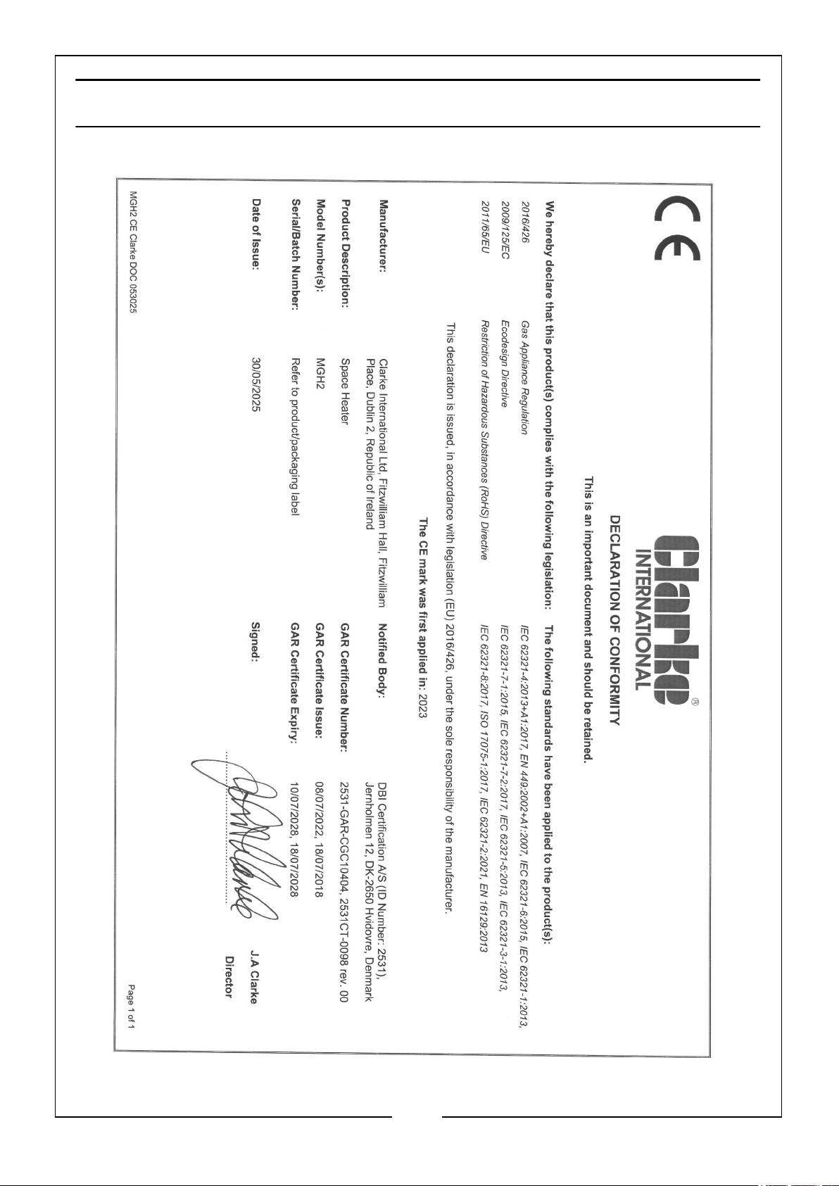
DECLARATION OF CONFORMITY - CE
18
Parts & Service: 020 8988 7400 / E-mail: [email protected] or [email protected]
Page 19
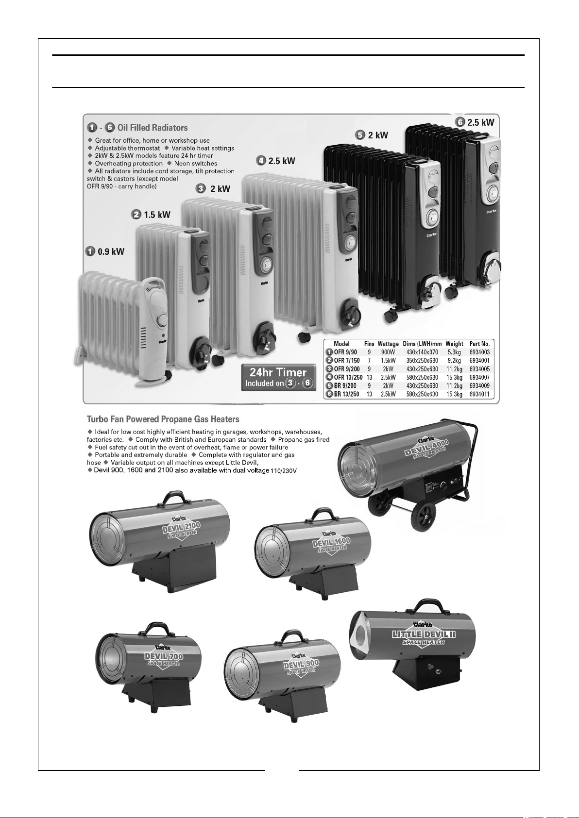
OTHER HEATERS FROM THE CLARKE RANGE
19
Parts & Service: 020 8988 7400 / E-mail: [email protected] or [email protected]
Page 20

 Loading...