

Page 1
IMAGE
https://harrissupplyind.com - To Order Parts Call 608-268-8080
Operator's
26E
Manual
READ THIS BOOK
This book has important information for the use and safe operation of this machine. Failure to read this
book prior to operating or attempting any service or maintenance procedure to your Clarke machine
could result in injury to you or to other personnel; damage to the machine or to other property could occur
as well. You must have training in the operation of this machine before using it. If you cannot read
English, have this manual explained fully before attempting to operate this machine.
Si Ud. o sus operadores no pueden leer el Inglés, se hagan explicar este manual completamente antes
de tratar el manejo o servicio de esta máquina.
®
All directions given in this book are as seen from the operator’s position at the rear of the machine.
For new books write to: Clarke
Form No. 70216B 5/05 Clarke® Printed in the U.S.A.
®
, 2100 Highway 265, Springdale, Arkansas 72764.
Page 2

CONTENTS OF THIS BOOK
https://harrissupplyind.com - To Order Parts Call 608-268-8080
Operator Safety Instructions .................................................................................. 3
Introduction and Machine Specifications..................................................................5
Transporting the Machine ........................................................................................6
Machine Controls ....................................................................................................7
Electrical Instructions 115V.....................................................................................10
How to Prepare the Machine for Operation ..............................................................11
Machine Operating Instructions ...............................................................................12
Maintenance Instructions ........................................................................................15
SECTION II PARTS AND SERVICE
How to Correct Problems in the Machine.................................................................20
Final Assembly Drawing..........................................................................................22
Final Assembly Parts List .......................................................................................23
Recovery Tank and Hose Assembly ........................................................................24
Handle Assembly ....................................................................................................25
Rear Panel Assembly..............................................................................................26
Solution Tank Assembly..........................................................................................27
Frame Assembly.....................................................................................................28
Frame Assembly Plumbing Detail ...........................................................................29
Drive Assembly .......................................................................................................30
Brush Assembly......................................................................................................31
Recovery Tool Assembly .........................................................................................32
Available Accessories .............................................................................................33
Electrical Schematic ...............................................................................................34
Wiring Diagram .......................................................................................................35
Flow Diagram ..........................................................................................................36
Page -2- Clarke® Operator's Manual IMAGE 26E
Page 3
OPERATOR SAFETY INSTRUCTIONS
https://harrissupplyind.com - To Order Parts Call 608-268-8080
WARNING AVERTISSEMENT ADVERTENCIA
DANG ER : Failure to read and observe all DANGER statements could result in
severe bodily injury or death. Read and observe all DANGER
statements found in your Owner's Manual and on your machine.
WARNING: Failure to read and observe all WARNING statements could result
in injury to you or to other personnel; property damage could
occur as well. Read and observe all WARNING statements found in
your Owner's Manual and on your machine.
CAUTION: Failure to read and observe all CAUTION statements could result in
damage to the machine or to other property. Read and observe all
CAUTION statements found in your Owner's Manual and on your
machine.
DANGER: Failure to read the Owner's Manual prior to operating or attempting any service or
maintenance procedure to your Clarke machine could result in injury to you or to
other personnel; damage to the machine or to other property could occur as well.
You must have training in the operation of this machine before using it. If your
operator(s) cannot read English, have this manual explained fully before attempting
to operate this machine.
DANGER: Operating a machine that is not completely or fully assembled could result in injury
or property damage. Do not operate this machine until it is completely assembled.
Inspect the machine carefully before operation.
DANGER: Machines can cause an explosion when operated near flammable materials and
vapors. Do not use this machine with or near fuels, grain dust, solvents, thinners,
or other flammable materials.
DANGER: Using a machine with a damaged power cord could result in an electrocution. Do
not use the machine if the power cord is damaged. Do not use the electrical cord
to move the machine.
DANGER: Electrocution could occur if maintenance and repairs are performed on a unit that is
not properly disconnected from the power source. Disconnect the power supply
before attempting any maintenance or service.
DANGER: Electrocution could occur if the machine is used on a power circuit that repeatedly
trips or is undersized. Have a licensed electrician check the fuse, circuit breaker
or power supply, and/or contact your local Clarke distributor for assistance.
WARNING: Operating this machine from anywhere other than from the back of the machine could
result in injury or damage. Operate this machine only from the rear.
WARNING: This machine is heavy. Get assistance before attempting to transport or move it. Use
two able persons to move the machine on a ramp or incline. Always move slowly. Do
not turn the machine on a ramp. Do not stop and leave the machine on a ramp or incline.
Read the "Procedures For Transporting" in this manual before transporting.
WARNING: Machines can topple over if guided over the edges of stairs or loading docks and cause
injury or damage. Stop and leave this machine only on a level surface. When you stop
the machine, put all switches into their "OFF" position.
®
Clarke
Operator's Manual IMAGE 26E Page -3-
Page 4
WARNING: This machine is not equipped with a parking brake. Never leave the machine unattended.
https://harrissupplyind.com - To Order Parts Call 608-268-8080
For added safety, always place a chock in front of and behind the drive wheel.
WARNING: Maintenance and repairs performed by unauthorized personnel could result in damage or
injury. Maintenance and repairs must be performed by authorized Clarke personnel only.
WARNING: Electrical components of this machine can "short-out" if exposed to water or moisture.
Keep the electrical components of the machine dry. Wipe the machine down after each
use. For storage, keep the machine in a dry building.
WARNING: Operating a machine without observing all labels and instructional information could result
in injury or damage. Read all machine labels before attempting to operate. Make sure all
of the labels and instructional information are attached or fastened to the machine. Get
replacement labels and decals from your Clarke distributor.
WARNING: Wet floor surfaces can be slippery. Water solutions or cleaning materials used with this
type of machine can leave wet areas on the floor surface. These areas can cause a
dangerous condition for the operator or other persons. Always put "Caution" signs
around/near the area you are cleaning.
WARNING: Using water that is above 140°F can damage the machine. Do not use water where the
temperature is above 140°F.
CAUTION: Use of this machine to move other objects or to climb on could result in injury or damage.
Do not use this machine as a step or furniture. Do not ride on this machine.
CAUTION: Your machine warranty will be voided if anything other than genuine Clarke parts are used
on your machine. Always use Clarke parts for replacement.
CAUTION: Using a extension cord with your machine will result in a voltage drop and loss of power.
Do not use an extension cord.
CAUTION: Carpet damage can occur if carpet has not adequately dried before traffic resumes. Stay
off the carpet until it is dry.
Page -4- Clarke® Operator's Manual IMAGE 26E
Page 5
INTRODUCTION AND MACHINE SPECIFICATIONS
https://harrissupplyind.com - To Order Parts Call 608-268-8080
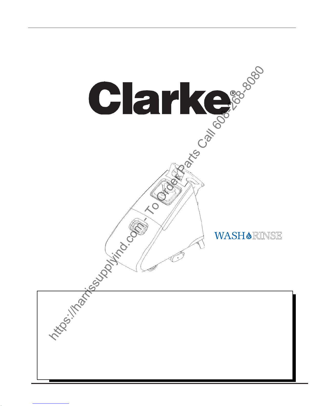
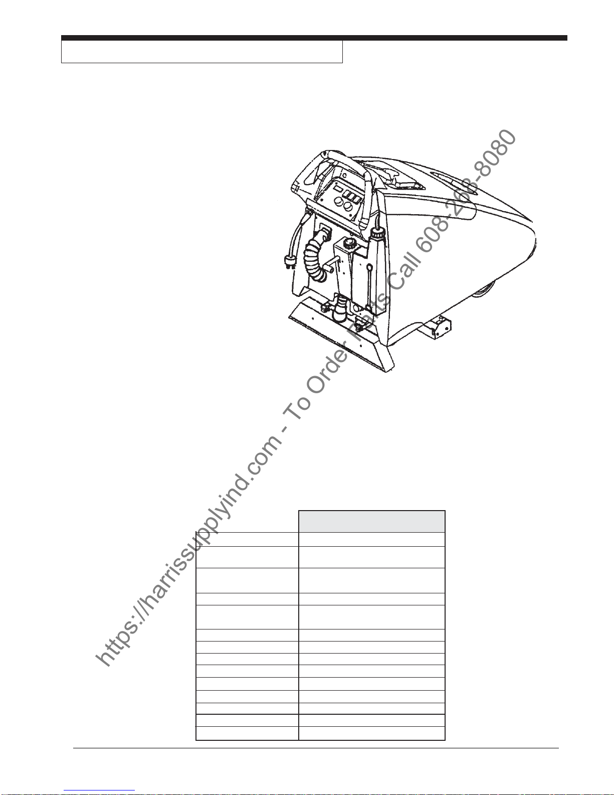
The IMAGE 26E is a one-piece, self-propelled carpet extractor designed for cleaning carpet. The machine applies
cleaning solution to the carpet and then rinses carpet and removes the dirty solution and soil with a recovery tool.
Features:
Easy to Operate
Interex cleaning system.
Brush pressure gauge.
Improved Line of sight.
Adjustable brush pressure.
Adjustable traverse speed.
Quick change brush feature.
Rugged 10-gauge mainframe.
Large capacity, compact size.
Easy access for serviceability.
Large recovery tank opening for easy cleaning.
Smooth 8", non marking, tread-less drive wheels.
Accessory tool connection.
No fatigue, dead man switch mounted on control handle.
75 ft, detachable, 12/3 power cord with twist lock connector.
Tangential discharge vac motor.
Circuit breaker protection for traverse, brush, and pump motors.
Automatic shut-off when recovery tank is full.
Adjustable bypass pump.
Two brushes: Maintenance (less aggressive), Restoration (more aggressive).
Solution level indicator.
Solution Pump 150 psi Adjustable By-pass
Solution Tank 25 Gallon
Capacity
Recovery Tank 25 Gallon
Capacity
Water Lift 136" Functional WL 95/CFM
Vacuum Tangential discharge,
Electrical 115V, 60 Hz
Operating Amps 12.0 Max.
Power Cable 75 ft. 3-Wire Grounded
Spray Jets Quick Change Nozzles
Brush Size 4" x 23"
Dimensions 44" x 26" x 36"
Weight 210 lbs.
Shipping Weight 280 lbs.
Dimensions 56" x 28" x 46" (41.7 cu. ft.)
®
Clarke
Operator's Manual IMAGE 26E Page -5-
IMAGE 26E, 115V
Three stage motor
Page 6
TRANSPORTING THE MACHINE
https://harrissupplyind.com - To Order Parts Call 608-268-8080
How to Put the Machine in a Van or Truck
WARNING: The machine is heavy. Make
sure you use two able persons
to help assist the machine up
the ramp.
1. Make sure the loading ramp is no less than eight
feet long and strong enough to support the
machine.
2. Make sure the ramp is clean and dry.
3. Secure the ramp in position.
4. Lift the recovery tool brush assembly into the
storage position.
5. Align the machine on a level surface ten feet in
front of the ramp.
6. Push the machine to the top of the ramp.
7. Tie down the machine.
How to Remove the Machine From A Van
Or Truck
1. Make sure there are no obstructions in the area.
2. Make sure the unloading ramp is no less than
eight feet long and strong enough to support the
machine.
3. Make sure the ramp is clean and dry.
4. Secure the ramp in position.
5. Untie the machine.
WARNING: The machine is heavy. Make
sure you use two able persons to
assist the machine down the
ramp.
6. Assisting the machine down the ramp, position
yourself to maintain a slow downward speed.
Page -6- Clarke® Operator's Manual IMAGE 26E
Page 7
THE CONTROLS
https://harrissupplyind.com - To Order Parts Call 608-268-8080
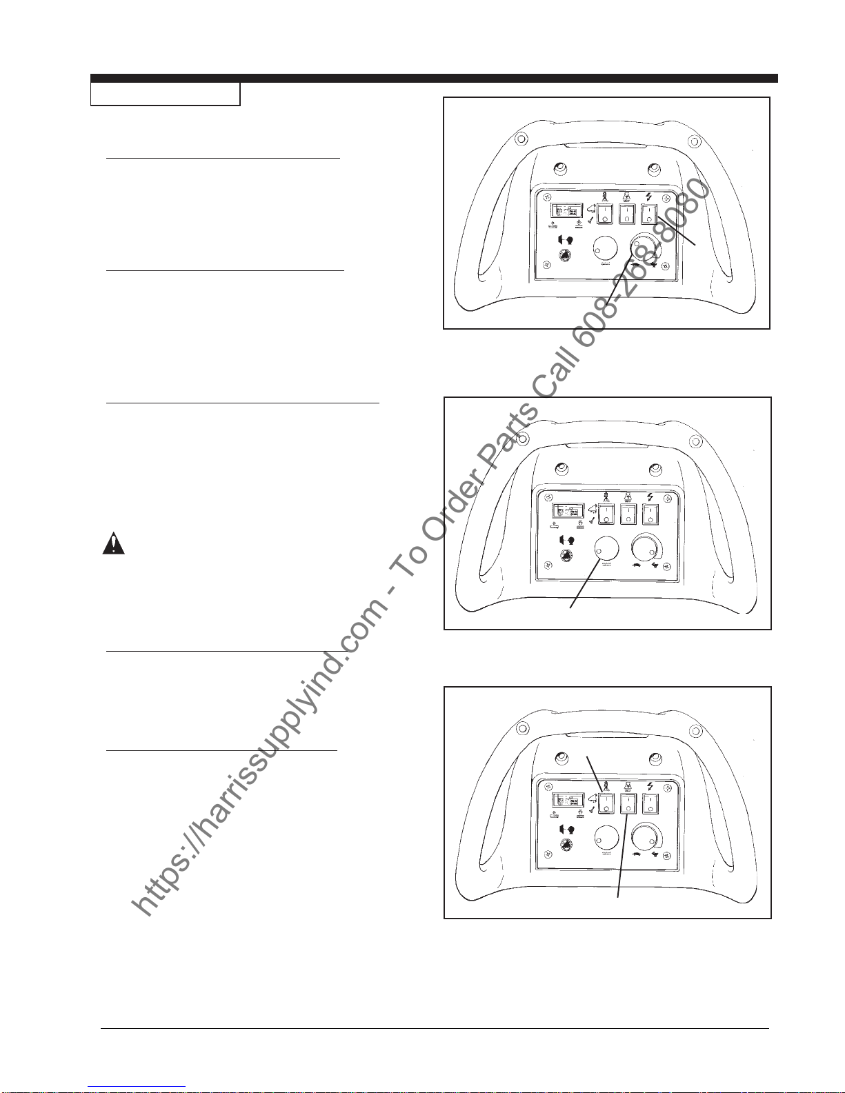
The Power Switch (See figure 1, A)
The power switch is located on the control panel.
The power switch must be on before any
function of the machine will work.
The Traverse Knob (See figure 1, B)
The traverse knob is located on the control panel just
below the power switch. The traverse knob controls the
speed of the machine. For faster speeds, turn the knob
to the right. For slower speeds, turn the knob to the left.
Variable Pump Pressure (See figure 2, C)
The variable pump pressure knob is located in the
middle of the control panel. This knob can be adjusted
clockwise to increase flow and pressure or counterclockwise to decrease flow and pressure. If streaking
occurs increase pressure setting.
A
B
Figure 1
WARNING: Do not operate the pump if the
solution tank is empty. Damage to
the pump could occur.
The Vacuum Switch (See figure 3, D)
The vacuum switch is located on the control panel to
the left of the power switch.
Accessory Switch (See Figure 3, E)
The accessory switch is located to the left of the
power switch. This switch controls where the
solution is applied - floor or accessory connection.
C
Figure 2
E
D
®
Clarke
Operator's Manual IMAGE 26E Page -7-
Figure 3
Page 8
THE CONTROLS (cont.)
https://harrissupplyind.com - To Order Parts Call 608-268-8080
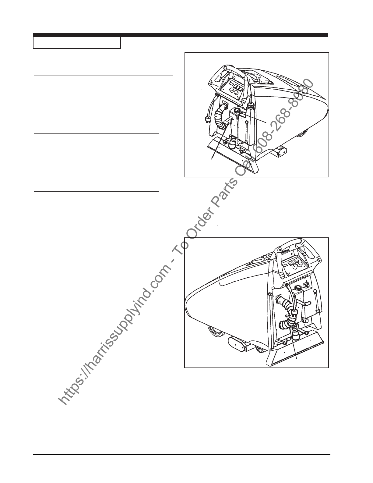
The Brush Adjustment Control Knob (See figure
4, A)
The brush adjustment control knob is located at the
rear of the machine. The knob is adjustable for many
types of carpet.
The Recovery Tool Handle (See figure 4, B)
The recovery tool handle is located on the back of
the machine. This handle lowers the recovery tool
and brush.
A
B
Accessory Hose Connector (See figure 5, C)
The accessory hose connector is used to hook-up
optional auxiliary floor tools and to redirect the
solution flow. Use hose coupler (P.N. 30108A) to
connect accessory hose to recovery shoe hose.
(See page 33.)
Figure 4
Page -8- Clarke® Operator's Manual IMAGE 26E
C
Figure 5
Page 9
THE CONTROLS
https://harrissupplyind.com - To Order Parts Call 608-268-8080
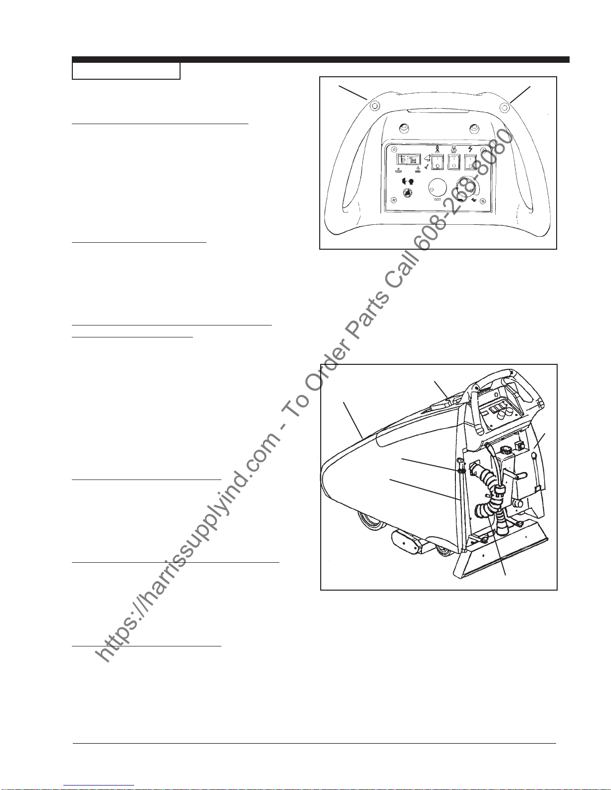
The Traverse Switch (See figure 6, A)
The traverse switch is located on the control handle.
Light pressure with the thumb or hand activates the
traverse for forward movement. Only one switch
needs to be activated for unit to traverse. This
machine does not have reverse.
Rinse Tank (See figure 7, A)
A
A
The rinse tank is top center of the machine. The rinse
tank fill opening is located under the front cover.
Rinse Tank Drain Hose and Solution Level
Indicator (See figure 7, B)
The rinse drain hose is on the lower left at the back of
the machine. To drain, pull the clear hose free of the
top hosebarb and lay the hose into drain. Reconnect
when finished.
*TIP: To drain, disconnect from top plug and insert
into vacuum hose up to the adaptor (E). Turn
vacuum on. Empty recovery tank.
.
Recovery Tank (See figure 7, C)
The recovery tank is mounted in the rear center
position on the machine.
Figure 6
C
A
F
E
B
Recovery Tank Drain Hose (See figure 7, D)
The recovery drain hose is located at the center
left at the back of the machine.
Chemical Tank (See figure 7, F)
The chemical tank is located on the rear right on the
back of the machine.
®
Clarke
Operator's Manual IMAGE 26E Page -9-
D
Figure 7
Page 10
115V Electrical Connection Instructions
https://harrissupplyind.com - To Order Parts Call 608-268-8080
DANGER: Electrocution and/or damage could
occur if this machine is plugged
into anything other than the correct frequency as specified on the
nameplate. This machine will
operate only on AC frequency and
on electrical voltage shown on the
nameplate. Make sure you have
the correct frequency and voltage
before connecting the power cord
to an outlet. The machine has a
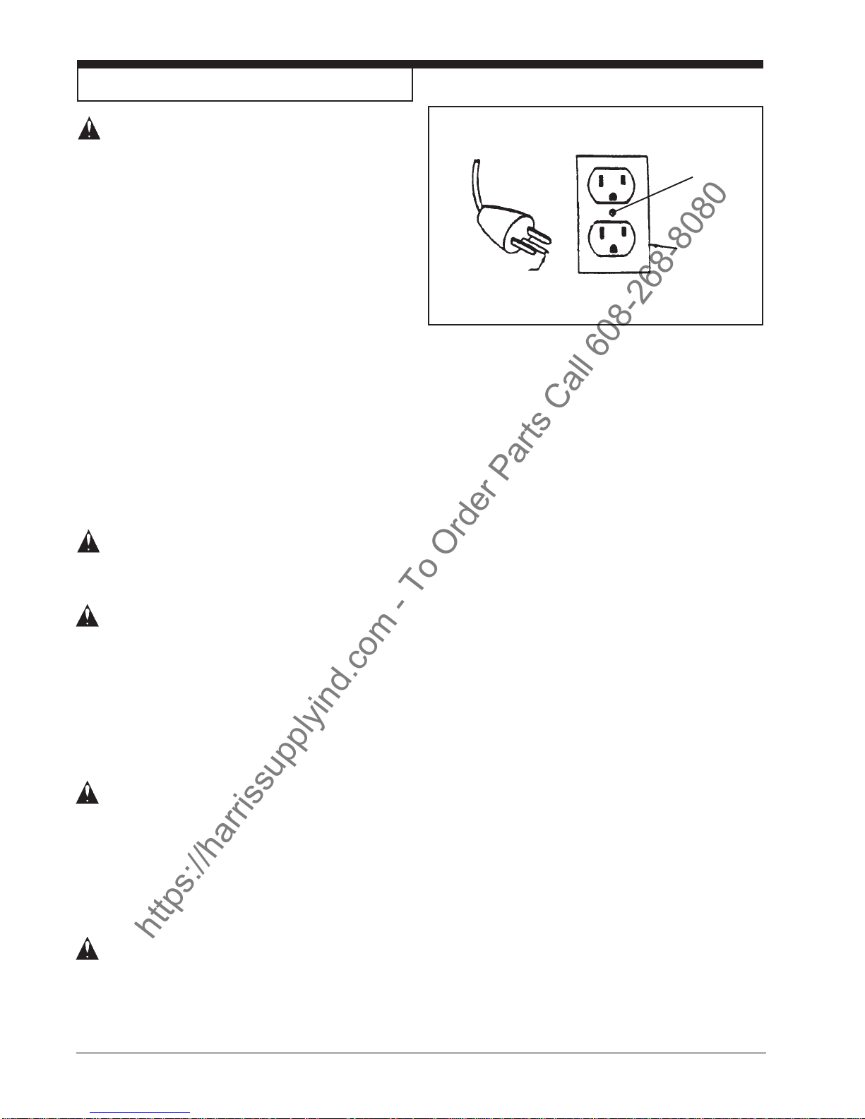
plug as shown in figure 8.
This machine must be connected to an electrically
ground circuit in order to protect the operator from
electric shock. This machine has an approved power
cord with three conductors as well as a plug with three
terminals. Connect the plug into a three holed receptacle.
For maximum protection against electric shock, use a
circuit that is protected by a ground fault circuit interrupter.
This machine uses a 115V AC 60 cycle electrical circuit.
Make sure you have the correct frequency and voltage
before connecting the power cord to an outlet. Do not
use an adaptor to plug in this machine. Contact an
electrical contractor and have a 3-prong receptacle
installed.
Ground Pin
Plate
Screw
Outlet
must be
connected
to the
electrical
ground
Figure 8
DANGER: Electrocution could occur if the
machine is exposed to water or
rain. Keep the machine in a dry
building.
DANGER: Electrocution could occur if ma-
chine is improperly connected to
the electrical system. To prevent
possible electric shock, always use
a 3-wire electrical system connected to an electrical ground.
For maximum protection against
electrical shock, use a circuit that
is protected by a ground fault circuit interrupter. Consult your electrical contractor.
DANGER: Electrocution could occur if the
ground pin is tampered with in any
way. Do not cut, remove, or break
the ground pin. Do not try to fit a
three-terminal plug into a receptacle or connector body other than
a three plug receptacle or connector body. If the outlet does not fit
the plug, consult your electrical
contractor.
DANGER: Electrocution could occur if the
machine is used with a damaged
plug or power cord. If the cords or
plugs are worn or damaged in any
way, have them replaced by an
authorized service person or electrician.
Page -10- Clarke® Operator's Manual IMAGE 26E
Page 11
HOW TO PREPARE THE MACHINE FOR OPERATION
https://harrissupplyind.com - To Order Parts Call 608-268-8080
DANGER: Failure to read the operator’s
manual before operating this
machine could result in injury to
you or to other personnel,
damage to the machine or to
other property as well.
CAUTION: The antifreeze solution that is
shipped in your machine will
damage carpet. Flush the
antifreeze solution from the
system before using the machine.
Your new Clarke machine has been shipped with antifreeze
solution in the machine's system. This antifreeze must
be flushed out prior to using the machine the first time.
To flush the antifreeze solution follow this procedure:
1. Plug both ends of the power cord in to the right
connection.
2.Move machine to a non-carpeted area with a floor
drain.
3.Position the machine over the drain.
NOTE: Drive wheels must be lifted off the ground
for this step.
4.Drain chemical tank completely, then add
approximately 1/4 gallon clear water to soap tank.
5.Add a minimum of five (5) gallons of clean water to the
solution tank.
NOTE: Do not use water that is hotter than 140°F.
6. Press the power switch to the "ON" position.
7. Press the accessory switch to "FLOOR" position.
8. Turn solution flow valve to maximum setting.
9. Press either of the traverse switches to activate
spray.
10. Allow the solution to run through the machine over the
floor drain until the solution tank is empty.
CAUTION: Cleaning solution in the
machine and tools can leak
onto the carpet and cause light
spots or stains. Do not leave
the extractor or other cleaning
machines or tools on the carpet
when not in use.
®
Clarke
Operator's Manual IMAGE 26E Page -11-
Page 12
MACHINE OPERATING INSTRUCTIONS
https://harrissupplyind.com - To Order Parts Call 608-268-8080
DANGER: Failure to read the operator’s
CAUTION: Pump damage can occur if the
Recommendations for Best Wash -n-Rinse
Cleaning Results
1. Vacuum carpet thoroughly before cleaning.
2. Precondition spots, stains and any high traffic
areas as needed.
3. Clean carpet by following the instructions in this
section. See "How to Operate the Machine".
4. After cleaning, dry carpets by using Clarke's
Direct Air carpet dryer or by using fans. Windows
should be open to assist in proper drying.
manual before operating this
machine could result in injury to
you or to other personnel,
damage to the machine or to
other property as well.
pump is operated without water
in the solution tank. Do not
activate the pump if the solution
tank is empty.
How to Operate the Machine
1. Put water into rinse tank and cleaning solution
into the chemical tank. Clarke recommends
using Clarkare® Extractor Concentrate as a
cleaning solution.
Wash-n-Rinse Operating Instructions:
a.) Soap tank must be filled with liquid soap
only. It must be at the consistency similar
to that of water.
b.) Pump setting must be placed in the maximum
range.
c.) Soap concentration used for pre spray jets is
factory set at 4:1 ratio. To change
concentration, dilute soap in container 50%
water to 50% solution to equal 2:1 ratio etc.
DA N GE R : Electrocution could occur if
machine is connected to an
electrical outlet that is not
properly wired or grounded.
Always use a 3-wire electrical
system connected to electrical
ground. For maximum protection, use a circuit that is protected by a ground fault circuit
interrupter (GFCI). Consult your
electrical contractor.
2. Connect the power cord to the machine and to
the correct electrical source.
3. Press the power switch to the "ON" position.
Page -12- Clarke® Operator's Manual IMAGE 26E
Page 13
MACHINE OPERATING INSTRUCTIONS
https://harrissupplyind.com - To Order Parts Call 608-268-8080
4. Press vacuum switch to the "ON" position.
5. Select "Floor" setting on the accessory switch.
6. Turn the traverse speed control to the desired
position.
7. Turn pump pressure knob to desired setting.
8. Lower the recovery tool.
9. Apply pressure to either traverse switch on the
control handle.
4 8 12
3
7
11
Finish
10 6 2
13
9
5
10. Adjust the brush to the proper carpet height
setting.
11. Guiding the machine by the control handle, move
across the floor in the forward direction.
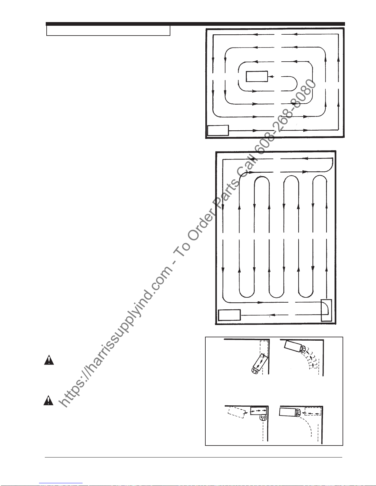
12. Follow the path sequence.
NOTE: By properly planning the cleaning pattern, a
minimum number of turns will need to be made.
See figures 10a and 10b.
13. When cleaning in a corner, change the accessory
switch to accessory, raise the brush, maneuver the
machine as illustrated in figure 11. Lower the
recovery tool, turn the accessory switch back to
"Floor" and proceed with cleaning.
NOTE: If the extractor removes an excess amount of
foam from the carpet, add a de-foamer such as
Clarkare ® Defoamer Concentrate to the recovery tank.
The amount needed will vary according to the amount of
detergent already in the carpet.
To stop the machine follow these procedures:
1. Press the accessory switch to "ACCESSORY".
2. Release pressure from the traverse switch on the
control handle.
3. Raise the recovery tool handle to the “storage”
position.
4. Wait 5 - 10 seconds to allow all dirty solution to
reach the recovery tank, and then raise the recovery tool handle to the “OFF” position.
Start
1
Figure 10a
9
8
10 7 6 5 4 3 2 1
11
Finish
12
Figure 10b
Start
WARNING: Failure to turn all switches to
WARNING: Machine can roll if left parked
®
Clarke
Operator's Manual IMAGE 26E Page -13-
the “OFF” position could result
in injury or machine damage.
Always position all of the
switches into their "OFF"
position when not in use.
or unattended on an un-level
surface and cause damage or
injury. This machine is not
equipped with a parking brake.
Never leave the machine
unattended. For added safety,
always place a chock in front of
and behind the drive wheel.
1
3
2
4
Figure 11
Page 14

MACHINE OPERATING INSTRUCTIONS
https://harrissupplyind.com - To Order Parts Call 608-268-8080
After Each Use of the Machine
1. Disconnect the power cord from the outlet.
2. Drain and rinse out the recovery and the solution tank
following this procedure:
For Recovery Tank
a. Position the machine close to a floor drain or an
appropriately sized bucket or container.
b. Remove the hose from the fitting on the back of
the machine.
c. Put the end of the hose over a drain or bucket.
d. Open the drain plug latch to release and drain
tank.
For Rinse Tank
a. Remove clear hose from top connector.
b. Position in appropriate container or floor drain.
c. Drain tank.
*TIP: To drain, disconnect from top plug and insert
into vacuum hose up to the adaptor. Turn vacuum on.
Empty recovery tank.
NOTE: Make sure to drain both the recovery tank
and the rinse tank. For chemical tank, solution
should be emptied into proper storage container.
Remaining soap in line must be removed by running
water through rinse tank.
3. Use a clean dry cloth to wipe out both tanks and the
recovery tool, both inside and out.
4. Leave the tanks and drain hoses open to dry in the air.
5. Inspect and clean the filter screen between the
solution tank and pump.
6. Inspect and clean the prespray jets and the rinse jets.
After Cleaning the Carpet
1. Do not walk or place heavy objects on the carpet for
at least four hours or until the carpet is dry to the
touch.
2. Vacuum right after the carpet is dry and vacuum at
least once a week, or as often as needed.
CAUTION: You are responsible for Operator
error. Clarke will not be held
liable for damage to the carpet
or for poor results because of the
operator's errors.
3. To speed drying time of the carpet try a Clarke Direct
Air carpet dryer.
Page -14- Clarke® Operator's Manual IMAGE 26E
Page 15

MAINTENANCE
https://harrissupplyind.com - To Order Parts Call 608-268-8080
WARNING: Machine damage or injury could
occur if maintenance and repairs
are performed by unauthorized
personnel. Maintenance and
repairs must be done by authorized
personnel only. Use only genuine
Clarke parts.
NOTE: For maintenance of optional tools, read the
manual that is supplied with the tools.
Always empty the solution and recovery tanks
before performing any maintenance to the machine.
After Each Use of the Machine
1. To prevent damage to the valves and to the jets, flush
one gallon of clean water through the solution system.
2. If the auxiliary tools have been used, be sure to flush
them out with clean water.
3. Disconnect the power cord from the outlet.
4. Drain and rinse out the recovery tank.
5. Use a dry cloth to wipe the recovery tank, and the
tools both inside and out.
6. Inspect and clean the filter screen in the inlet hose
to the pump.
How to Prevent Freezing Temperature Damage
To prevent damage from freezing temperatures, follow
this procedure:
1. Remove any solution remaining in the solution tank.
2. Make sure that the machine and the pump are
completely dry.
3. Make sure the machine is at room temperature
before using it.
Electrical
NOTE: For electrical repairs, return this machine to a
Clarke authorized repair center.
®
Clarke
Operator's Manual IMAGE 26E Page -15-
Page 16
MAINTENANCE
https://harrissupplyind.com - To Order Parts Call 608-268-8080
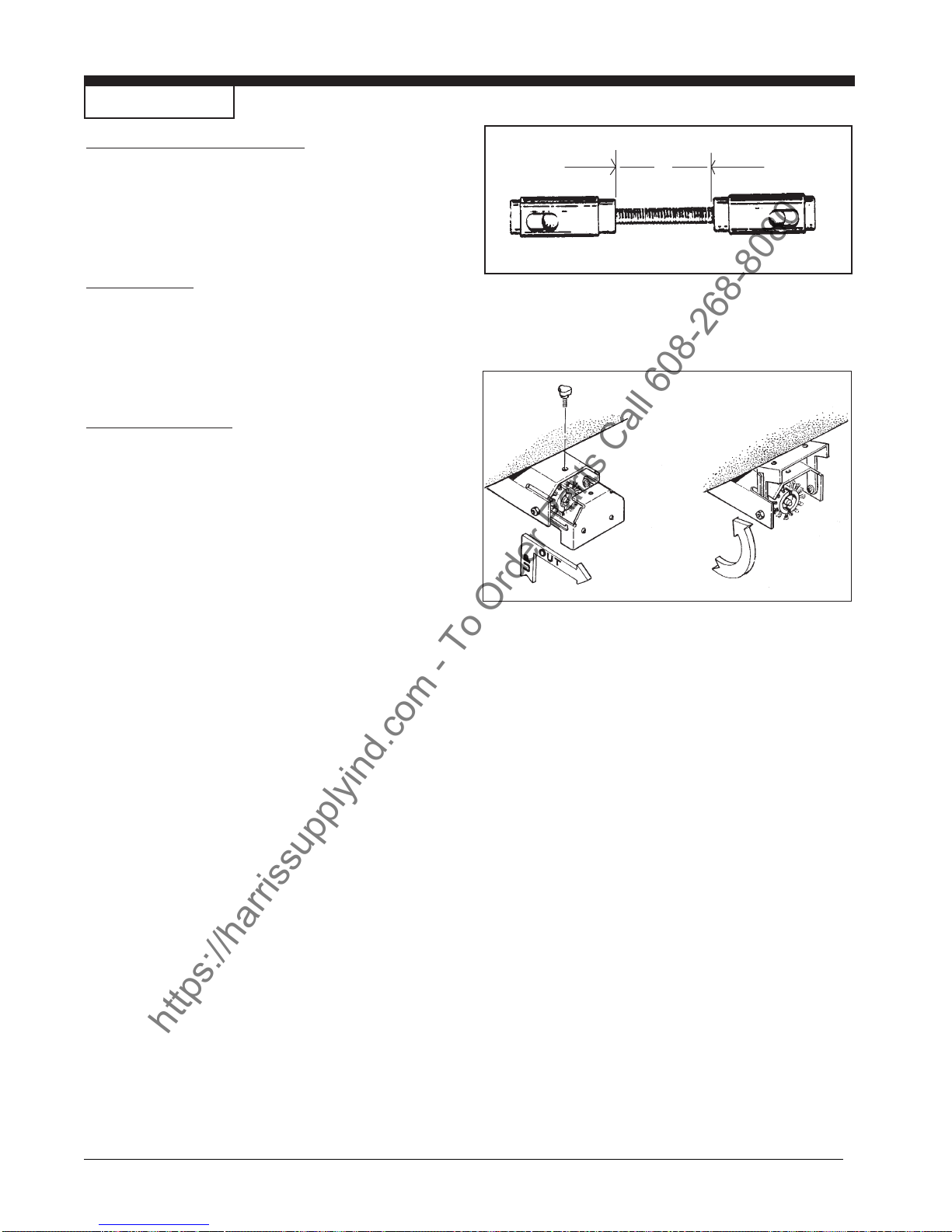
Recovery Tool (See figure 12)
The recovery tool is factory adjusted for optimum
performance. If further adjustment is necessary,
remove adjustment assembly. Loosen locknuts and
lengthen or shorten dimension "A" as required.
A
Vacuum Motor
This machine has a vacuum motor that uses carbon
brushes. The carbon brushes in the motor must be
checked every three months, or every 500 hours of
operation, whichever comes first.
Changing the Brush
The machine comes with one brush (PN 30166A):
1. Black - for everyday, routine carpet maintenance
(Part No. 30167A). This brush must be purchased separately.
2. Black with white bristles on end - for heavyduty restoration carpet cleaning (Part No.
30166A). This brush is supplied with the
machine.
These brushes are reversible. After bristles are worn
reverse the direction the brush was placed on the
machine (see figure 13).
The brush can be changed or rotated by using the
quick change brush door (see figure13):
Figure 12
Figure 13
1. Remove clamping knob.
2. Raise brush housing door approximately ¼
inch and pull out. Swing door up to remove
brush.
3. Remove the spacer and brush from the brush
housing.
4. Place brush onto the shaft. Slide brush in
and rotate until the pins catch.
5. Place spacer on shaft.
6. Place end cap back onto the shaft.
7. Tighten clamping knob.
Page -16- Clarke® Operator's Manual IMAGE 26E
Page 17

MAINTENANCE
https://harrissupplyind.com - To Order Parts Call 608-268-8080
Nozzles
To remove the nozzles to clean or change nozzles,
follow this procedure:
Recovery Tool
1. Grasp the nozzle cap assembly and twist
counterclockwise to remove assembly from the
spray bar.
2. Pull the nozzle out of the cap.
3. Clean or replace the nozzle.
4. Replace nozzle back into cap.
5. Twist nozzle cap assembly back onto the
spray bar.
Brush Housing
1. Pull nozzle assembly out to the right hand
side of machine.
2. Firmly push nozzle in and turn 1/4 turn.
3. Pull nozzle out.
4. Clean and replace into nozzle assembly.
5. Replace nozzle assembly in brush housing.
®
Clarke
Operator's Manual IMAGE 26E Page -17-
Page 18

NOTES
https://harrissupplyind.com - To Order Parts Call 608-268-8080
Page -18- Clarke® Operator's Manual IMAGE 26E
Page 19

IMAGE 26E
https://harrissupplyind.com - To Order Parts Call 608-268-8080
®
Section II
Parts and Service Manual
®
Clarke
Operator's Manual IMAGE 26E Page -19-
(70216B)
Page 20
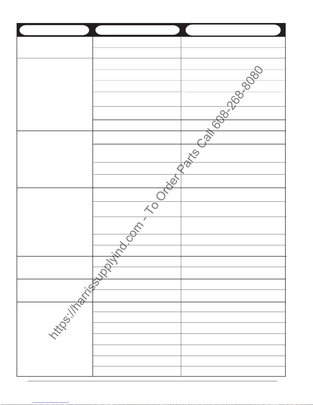
How to Correct Problems in the Machine
https://harrissupplyind.com - To Order Parts Call 608-268-8080
Problem
The machine does not move. The Power switch is off. Turn on the "Power" switch.
The traverse switch is defective. Contact an authorized service person
There is no solution flow. Solution control dial in wrong position. Turn dial to position for more flow.
Accessory Switch in wrong position. Change to desired position.
The solution tank is empty. Fill the solution tank.
There is an obstruction in the Remove the obstruction from the hose
solution hose or filter. or filter.
Solenoid is defective. Contact an authorized service person
Pump is defective Contact an authorized service person
The machine doesn't extract The recovery tank is full. Drain the recovery tank.
solution from the floor.
The recovery tool is not Lower and/or adjust the tool.
resting on the floor.
Filter screen plugged Clean screen and replace.
Opening in recovery tool is plugged. Clean and retry.
Cause
Action
The cleaning is not even. The brush is worn. Replace / reverse the brush.
The brush in not level. Level brush on floor using leveling srews on
brush door.
There is damage to the brush
module or spray assembly. Contact an authorized service person.
The solution level is low. Fill the solution tank.
Too little solution. Increase solution flow.
Uneven or no spray from nozzles. Dirty or plugged spray nozzles. Clean the spray assembly or nozzles.
Worn spray nozzles. Replace spray assembly or nozzles.
Water leaks from the spray Debris in the check valve. Contact an authorized service person.
nozzles with the pump "OFF".
Defective check valve. Contact an authorized service person.
There is no suction. The vac motor is not running. Turn vac motor switch on.
Vacuum hose obstruction. Remove the obstruction.
Vacuum intake screen covered. Clean and retry.
Vac hose damaged. Replace the hose.
The dome gasket worn or damaged. Replace the gasket.
Motor brushes are worn. Replace motor brushes.
Loose motor connection. Contact an authorized service person.
Page -20- Clarke® Operator's Manual IMAGE 26E
Page 21

NOTES
https://harrissupplyind.com - To Order Parts Call 608-268-8080
®
Clarke
Operator's Manual IMAGE 26E Page -21-
Page 22
26
https://harrissupplyind.com - To Order Parts Call 608-268-8080
Clarke
®
Image 26E
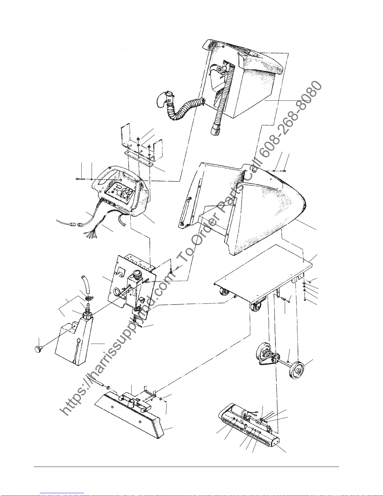
Final Assembly Drawing 5/05
1
12
28
2
3
8
27
34
39
35, 36,
37
40
38
24
23
32
41
14
21
25
30
11
12
31
4
5
6
7
8
9
10
13
Page -22- Clarke® Operator's Manual IMAGE 26E
29
20
19
12
16
18
16
33
14
15
16
17
Page 23
Clarke
https://harrissupplyind.com - To Order Parts Call 608-268-8080
®
Image 26E
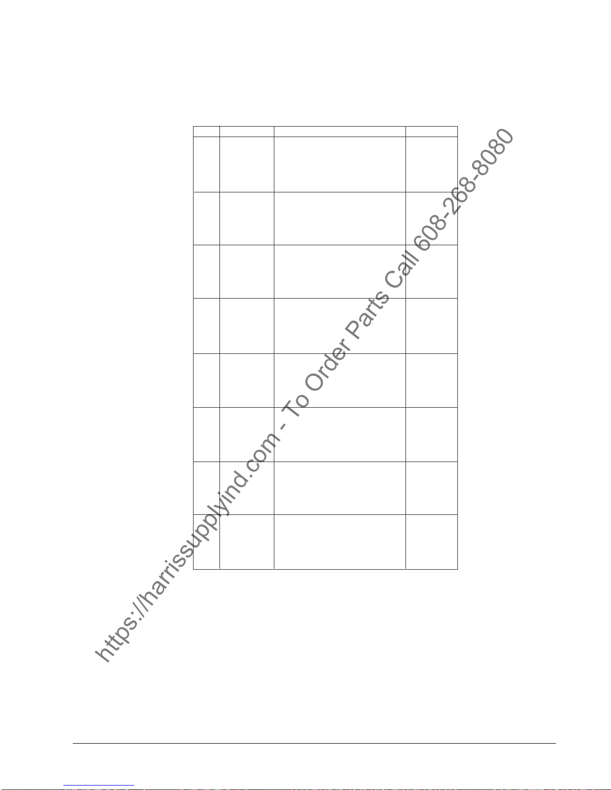
Final Assembly Parts List 5/05
Ref Part No. Description Qty
1 19196A Tank Asm, Recovery See pg. 24
2 980099 Washer 2
3 85389A Screw 2
4 19195A Tank Asm., Solution See pg. 27
5 14548A Main Frame Asm. See pg. 28
6 962481 Screw 4
7 87002A Washer, Flat 6
8 980645 Washer, Flat 8
9 170883 Washer, Lock 6
10 962244 Screw 6
11 Pg. 28 Spacer 2
12 81102A Nut 6
13 13005A Drive Asm. See pg. 30
14 50248A Clamp 1
15 Pg. 28 Nut, ¼-20 Elas. 6
16 Pg. 28 Washer, ¼ Flat 6
17 15727A Housing Asm, Brush See pg. 31
18 50249A Spacer (608210) 4
19 19225A Tool Asm., Recovery See pg. 32
20 980982 Washer #10 Flat 2
21 836711 Hairpin 1
23 17658A Panel Asm., Rear See pg.26
24 40149A Harness, Wiring 1
25 15350A Handle Asm. See pg. 25
26 962522 Screw 2
27 64247A Plate, Locking 1
28 170886 Washer 2
29 170803 Screw, 10-24 x ½ 2
30 962481 Screw, .25-20 x 1¼ 3
31 Pg. 28 Screw 2
32 30089A Tank, Chemical 1
33 85806A Screw, ¼-20 x 3/4 Hex 1
34 51210A Knob, Chemical Tank 1
35 30090B Cap, Chemical Jug 1
36 52333A Hosebarb 1
37 51208A Tip, Chemical Metering 1
38 80134A Fitting, Swiivel 1
39 10219A Cap Asm. (incl. 35, 36, 37, 38) 1
40 52476A Clamp 1
41 40167A Harness, Machine 1
NOTE: indicates a change has been made since the last
publication of this manual.
®
Clarke
Operator's Manual IMAGE 26E Page -23-
Page 24
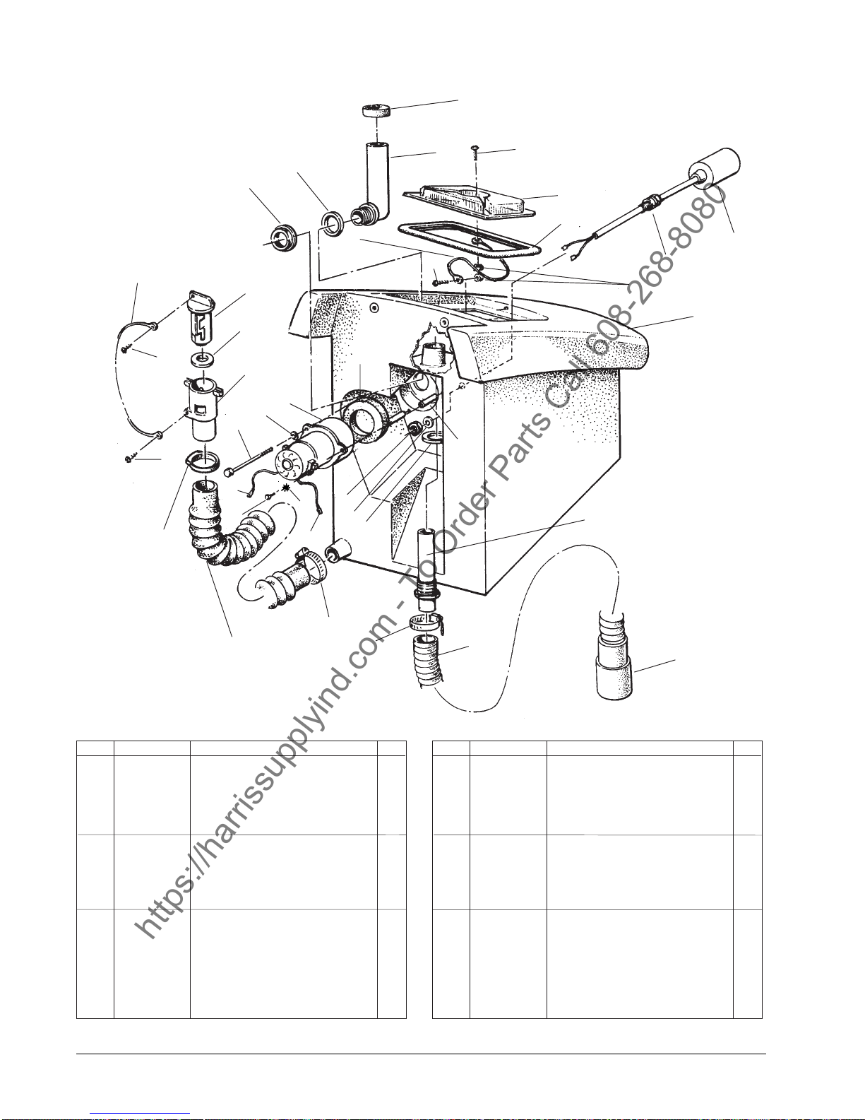
Clarke
https://harrissupplyind.com - To Order Parts Call 608-268-8080
Recovery Tank and Hose Assembly Drawing and Parts List 5/05
®
Image 26E
1
29
15
28
24
16
28
30
23
27
26
25
22
18
21,
21a
32
16
17
29
31
20
18
2
3
4
5
6
3
7
8
9
19
10
33
14
NOTE: indicates a change has been made since
the last publication of this manual.
Ref Part No. Description Qt y
1 58069A Screen, Vac Filter 1
2 39339B Tube, Stand Rec. Tank 1
3 962666 Screw, 10-24 x 3/4 2
4 36204C Lid, Recovery 1
5 34265A Gasket, Recovery Lid 1
6 47419A Switch, Float 1
7 56459A Strain Relief 1
8 81110A Nut, Hex 10-24 Elastic 2
9 38824B Tank, Recovery W/R 1
10 30132A Adaptor, Asm. Vacuum 1
11 51863A Cuff, Hose 2" 1
12 30462A Hose, Recovery 1
13 872010 Clamp, Hose 2
14 30449A Hose, Drain 1
15 832002 Clamp (Drain Valve) 1
16 47708A Terminal 1¼ FIMQD 2
17 82100A Locknut, ½" 1
13
12
11
Ref Part No. Description Qt y
18 837304 O-Ring, Retainer 2
19 58533A Spacer, Vac Motor 3
20 643418 Gasket, Vac Motor 1
21 44911R Motor, Vacuum 120V 1
21a 40833A Brush Asm., Carbon 2
22 87026A Washer, ¼ Flat 3
23 85728A Screw, ¼-20 x 4.00 Hex Hd. 3
24 962943 Screw, 8-18 x ½ 1
25 839401 Drain, Vavle 1
26 833407 Gasket, Drain 1
27 833901 Handle, Drain Valve 1
28 962987 Screw, 10-24 x 3/8 2
29 38020A Strap, Cover 2
30 920797 Locknut, Drain Valve 1
31 59877A Washer, ½NPT Sealing 1
32 980603 Washer 1
33 52365A Clamp, Hose 1
Page -24- Clarke® Operator's Manual IMAGE 26E
Page 25
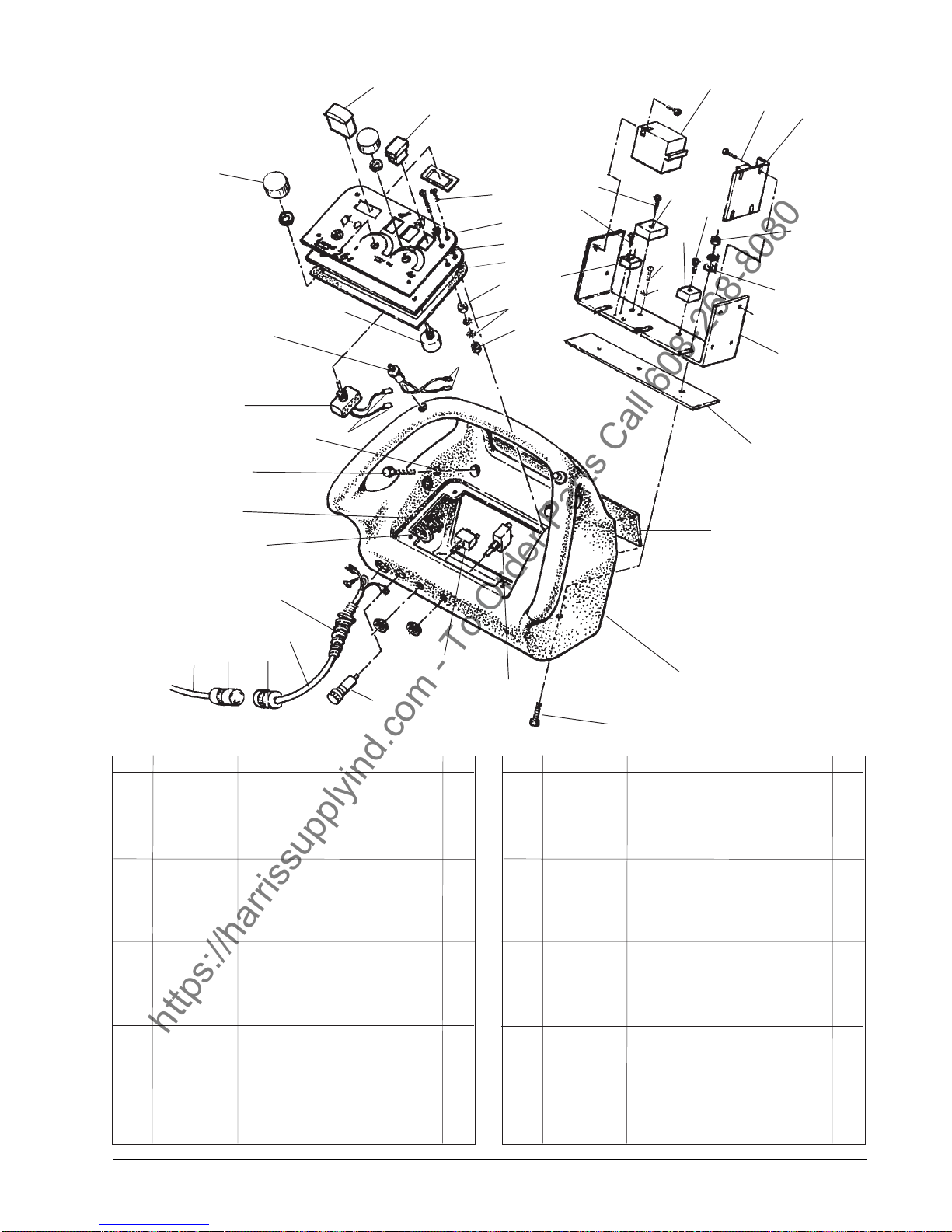
Clarke
https://harrissupplyind.com - To Order Parts Call 608-268-8080
®
Image 26E
Handle Assembly Drawing and Parts List 5/05
4
5
12
13
38
16
3
11
12
15
41
10
18
14
17
36
34
19
6
7
8
42
9
37
2
10
9
40
1
40
35
20
39
32
43
31
30
26
28
29
27
23
24,
25
Ref Part No. Description Qt y
1 52504A Control, Speed Variable 1
2 53077B Switch, Forward/Reverse 2
3 55502A Knob, Speed Control 2
4 44417A Meter, Brush Pressure 1
5 47316B Switch, Rocker DPST 3
6 962968 Screw, 10-24 x ½ Pan Hd 5
7 77369A Label, Control Panel 1
8 69385A Panel, Control 1
9 920200 Nut, Hex 10-24 2
10 980603 Washer, #10 3
11 912059 Terminal Block 1
12 962979 Screw 6-32 x ½ PN 4
13 41805A Contactor, Wire 115V 1
14 48416B Relay, Isolation 115V 1
15 85307A Screw, 10-32 x 5/8 1
16 41159A Control, Motor Speed 1
17 98470A Screw, 10-32 x 1 1
18 46103A Rectifer, Bridge 1
19 64246A Plate, Handle 1
20 64247A Plate, Retaining 1
21 34812A Handle, Control 1
22 41430B Breaker, Circuit 1.5 Amp 1
NOTE: indicates a
22
33
Ref Part No. Description Qty
23 40011A Breaker, Circuit 2.5 Amp 1
24 912201 Fuse Holder 115V 1
25 42911A Fuse, 1.25A - 250V 1
26 41975A Cord, Interconnect 1
27 912169 Plug, Electrical 1
28 911461 Connector, Electrical 1
29 42180A Cord, Power Less Receptacle 1
30 467504 Strain Relief 1
31 170870 Washer, Flat 7/8 1
32 82100A Locknut, ½" Conduit 1
33 85700A Screw, ¼-20 x 1¼ 3
34 980646 Washer, ¼ Flat 3
35 980645 Washer, 3/8 Flat 2
36 81102A Nut, ¼ -20 Elastic 3
37 45702A Potentiometer Asm. 1
38 85303A Screw, 8-32 x 3/8 4
39 962522 Screw, 3/8-16 x 2 2
40 47905A Terminal 4
41 962929 Screw, 10-32 x 3/8 1
42 30032A Gasket, Control Panel 1
43 30033A Gasker, Handle 1
NI 49791A Harness 1
21
change has been
made since the last
publication of this
manual.
®
Clarke
Operator's Manual IMAGE 26E Page -25-
Page 26
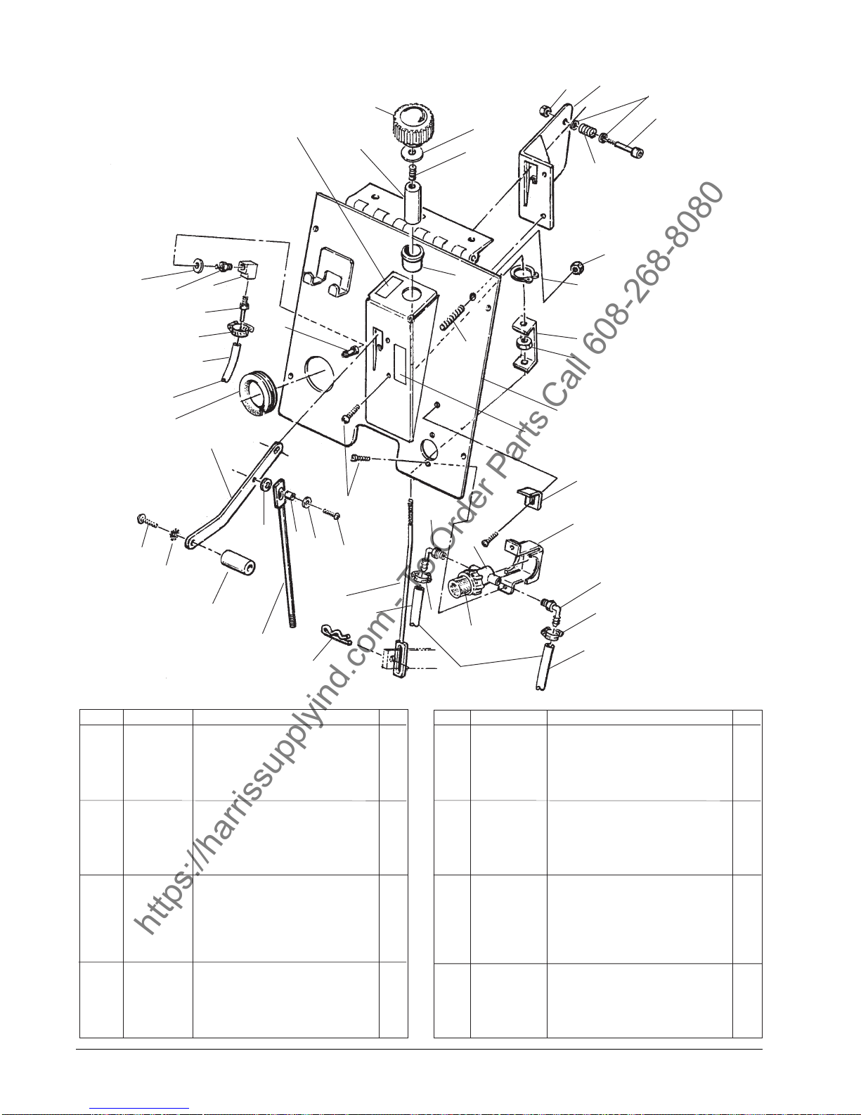
32
https://harrissupplyind.com - To Order Parts Call 608-268-8080
From B
(pg. 28)
29
24
16
17
27
28
23
Clarke
®
Image 26E
Rear Panel Assembly Drawing and Parts List 5/05
5
3
10
32
4
35
1
2
25
38
36
18
11
12
6
7
8
9
5
31
37
19
32
22
26
21
30
20
To
Pump
34
33
NOTE: indicates a change has
been made since the last publication of this manual.
Ref Part No. Description Qt y
1 77366A Brush, Adjustment Label 1
2 61685A Control, Brush Height 1
3 55537A Knob, Head Pressure 1
4 86207A Screw, Set
5 81102A Nut, ¼-20 ESNA 2
6 66254A Plate, Wear 1
7 980692 Washer
8 80028A Bolt, Shoulder,
9 438360 Spring, Adjuster Lift 1
10 51535A Bushing,
11 68794A Cover, Rear 1
12 77367A Label, Rec. Tool 1
13 53050A Strainer, Bowl 80 x 80 Mesh 1
13A 50018A Bowl, Clear Filter 1
13B 54369A Gasket, Viton 1
13C 58061B Filter, Screen 1
14 61271A Bracket, Filter 1
15 732870 Elbow,
16 50248A Clamp, Hose #6 3
17 30425A Hose, Air
18 80062A Nut, 5/16-18 1
3
/8 -16 x 1½ 1
5
/16 Flat 2
5
/16 x 1 1
5
/8 1
3
/8 Barb. to ¼ MPT 2
3
/8 I.D. x 5/8 O.D. ref.
39
15
14
13
15
16
13A, 13B
13C
17
Ref Part No. Description Qt y
19 608210 Spacer 1
20 64490A Handle, Squeegee Lift 1
21 980666 Washer,
22 85389A Screw
23 64906A Lift, Recovery 1
24 39102A Trim-Frame 1
25 737140 Quick Disconnect 1
26 962430 Screw 1
27 55167A Hosebarb,
28 170040 Elbow, ¼ x 90 degree 1
29 697501 Reducer, ¼ NPT 1
30 65444A Lift, Brush 1
31 85391A Screw 4
32 980645 Washer,
33 836711 Pin 1
34 65447A Lift, Recovery Tool
35 857345 Ring, Retaining 1
36 60064A Bracket, Retaining 1
37 87618A Washer 1
38 51209A Pin, Chemical Jug 1
39 60491A Bracket, Chemical Jug 1
16
From
Tank
3
/8 Ext. Star 1
3
/8-16 x 5/8 PN 1
3
/8 x ¼ NPT 1
3
/8 Flat 3
Page -26- Clarke® Operator's Manual IMAGE 26E
Page 27
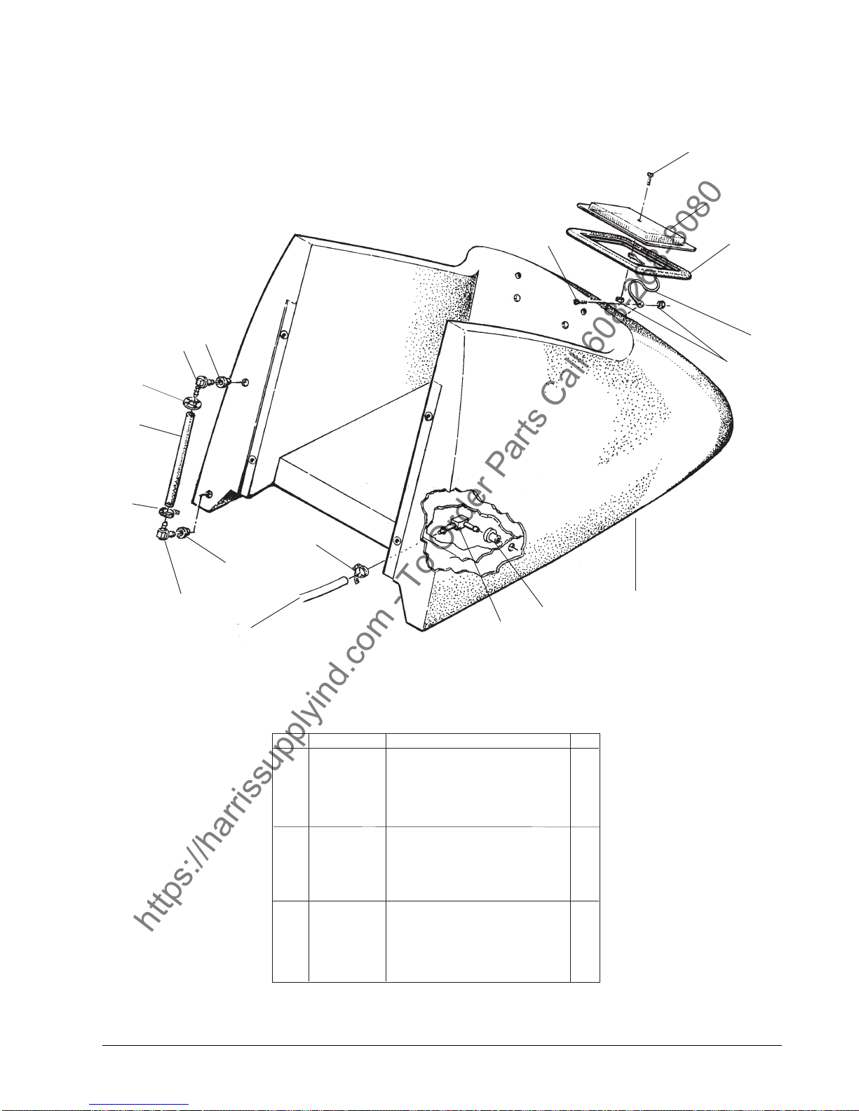
Clarke® Image 26E
https://harrissupplyind.com - To Order Parts Call 608-268-8080
Solution Tank Assembly Drawing and Parts List 5/05
14
2
12
11
13
10
10
1
9
3
4
5
15
9
6
7
To
8
Filter
Ref Part No. Description Qty
1 962666 Screw, 10-24 x 3/4 1
2 36200A Lid, Solution Tank 1
3 34266A Gasket, Solution Tank Lid 1
4 38020A Strap, Cover 1
5 81110A Nut, #10-24 ESNA 2
6 38825A Tank, Solution
7 51518A Bushing, Hose Connection 1
8 51526A Bushing, Drain 1
9 31242A Bushing, .50 I.D. 2
10 55189A Hosebarb, .50 x 90 degree 2
11 722030 Clamp, Hose #6 1
12 34712A Hose, Solution Level 1
13 60218A Plug, Drain 1
14 962798 Screw 1
15 50248A Hose Clamp 1
NOTE: indicates a change has been made sine the
last publication of this manual.
®
Clarke
Operator's Manual IMAGE 26E Page -27-
(Incl. #'s 7, 8, 9, 10)
1
Page 28
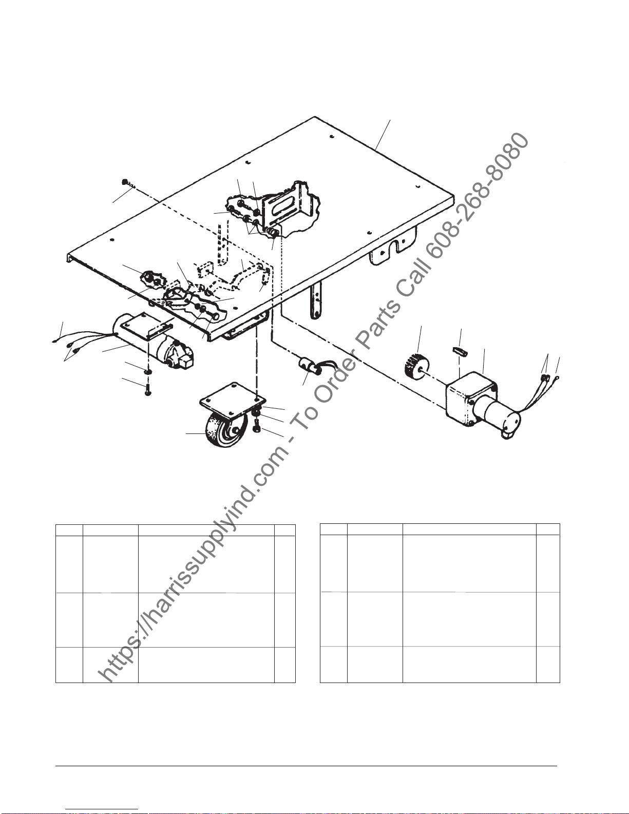
Clarke
https://harrissupplyind.com - To Order Parts Call 608-268-8080
Frame Assembly Drawing and Parts List 5/05
®
Image 26E
1
27
14
23
24
25
19
26
2
3
4
5
6
22
17
21
20
18
6
17
16
15
5
14
13
8
9
10
12
11
Ref Part No. Description Qt y
1 60485A Mainframe 1
2 58708A Pulley, Traverse Driven 1
3 915561 Key 1
4 44719A Motor, Traverse 1
5 47905A Terminal, ¼ FIMQD 4
6 911933 Terminal, #10 Ring 2
8 59622A See pg. 29 item 8 1
9 980645 Washer, Flat 3/8 (see final asm.) 16
10 170883 Lockwasher 3/8 (see final asm.) 14
11 85822A Screw, 3/8-16" x 5/8 8
12 51321A Caster, 5" Asm. 2
13 962794 Screw, 10-24 x 1 4
14 980982 Washer, #10 Flat 8
Page -28- Clarke® Operator's Manual IMAGE 26E
Ref Part No. Description Qt y
15 51206A Pump, 115V 1
16 85806A Screw, ¼-20 x 1 5
17 980646 Washer, ¼ Flat 10
18 50249A Spacer, Handle 5
19 60460A Arm, Brush Lift 1
20 60462A Arm, Brush Lift 1
21 60461A Arm, Lift 1
22 81102A Nut, ¼-20 5
23 962027 Screw, #8-32 x ½ 4
24 98470A Screw 1
25 980603 Washer 3
26 920224 N u t 1
27 84237A Screw, 10-32 x ½ 4
NOTE: indicates a change has been made since
the last publication of this manual.
Page 29
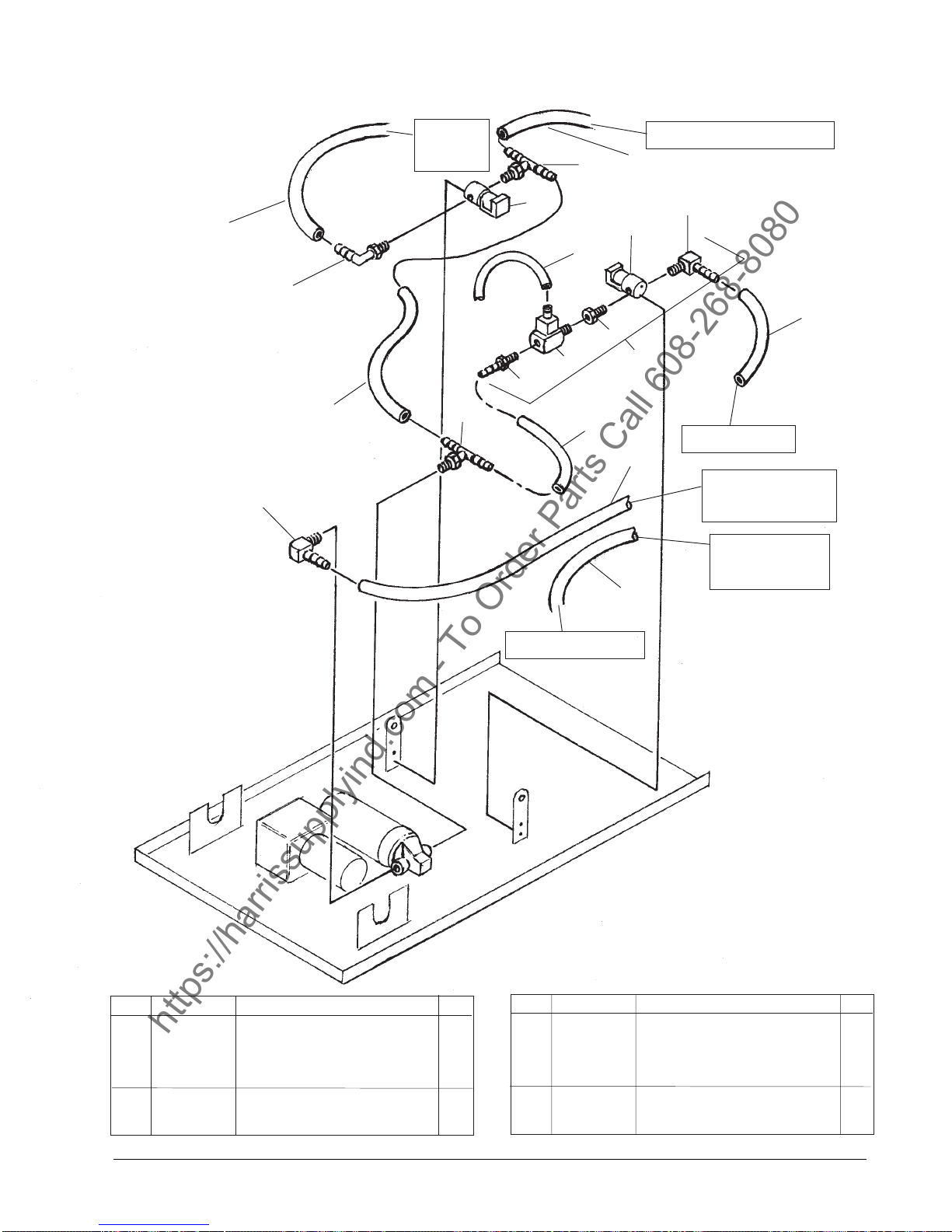
Clarke
https://harrissupplyind.com - To Order Parts Call 608-268-8080
Plumbing Detail Drawing and Parts List 5/05
®
Image 26E
13
To Rinse
Jets
•
•
12
8
To Quick Disconnect
13
9
8
15
•
9
7
6
14
5
11
•
3
•
4
To Pre-Spray
1
2
•
•
13
•
10
From Filter Asm.
Panel)
(Rear
To Filter Asm.
(Rear Panel)
From Rinse Tank
Ref Part No. Description Qt y Ref Part No. Description Qty
1 35168A Hose, Air 3/8 x 40" 1
2 53616A Elbow,
3 51212A Tee,
4 35147A Hose, Solution Intake 1
5 690209 Adaptor 1
6 51207A Injector, Chemical 1
7 851144 Bushing 1
8 59622A Valve, Solenoid 2
3
/8 MPT x 3/8 Barb. 1
3
/8 NPT x 3/8 Barb. 1
9 732870 Elbow, 3/8 Barb. to ¼ M 2
10 694117 Hose, Discharge 1
11 694116 Hose, Intake 1
12 59016A Tee, Branch ¼ x
13 30425A Hose,
14 10221A Injector Asm. (incl. 5, 6, 7, 8,& 9) 1
15 722021 Clamp, Hose 1
• = 50248A Clamp, Hose 8
3
/8 3
3
/8 1
®
Clarke
Operator's Manual IMAGE 26E Page -29-
Page 30
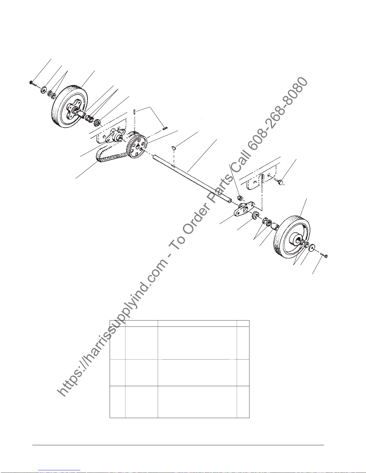
Clarke
https://harrissupplyind.com - To Order Parts Call 608-268-8080
Drive Assembly Drawing and Parts List 5/05
®
Image 26E
Form # 13005A
1
2
3
4
5
3
6
14
13
8
9
10
6
7
12
11
4
7
6
3
5
3
2
1
Ref Part No. Description Qty
1 85804A Screw, .25-20 2
2 87058A Washer, Retainer 2
3 58111A Seal, Oil 8
4 50273A Wheel, Drive 2
5 51124A Bearing, Roller Clutch 2
6 980679 Washer, 3/4 Flat 2
7 52495A Block, Bearing 2
8 58709A Sprocket, Traverse Driven 1
9 55400A Key, 3/16 x 5/32 1
10 67480A Shaft, Wheel 1
11 962481 Screw, ¼-20 x 1 4
12 81102A Nut, ¼-20
13 50915A Belt, Traverse Drive
14 962268 Set Screw (included w/#8) 2
NOTE: indicates a chang has been made since the
last publication of this manual.
Page -30- Clarke® Operator's Manual IMAGE 26E
(see final asm.)
(see final asm.)
4
1
Page 31
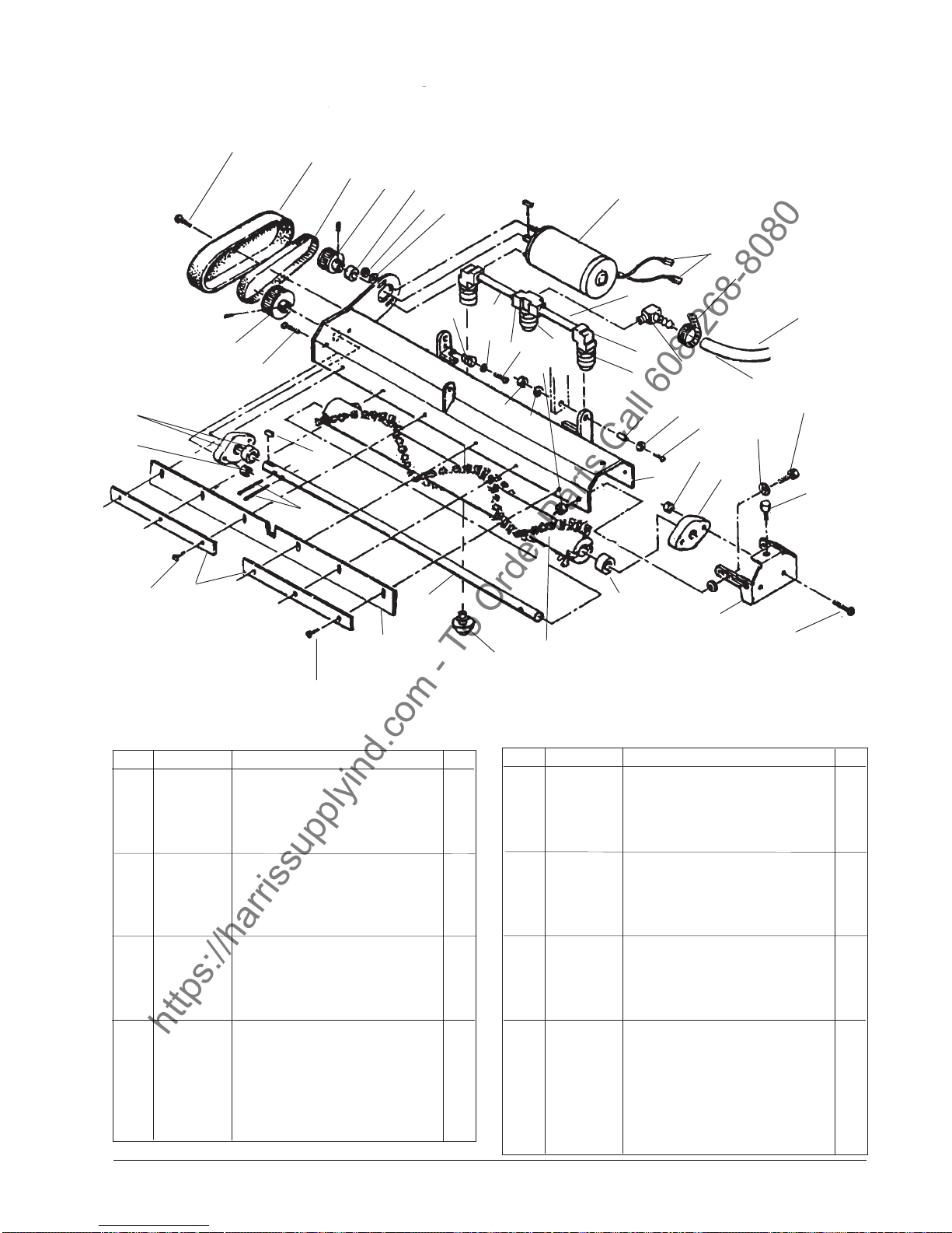
Clarke
https://harrissupplyind.com - To Order Parts Call 608-268-8080
Brush Assembly Drawing and Parts List 5/05
®
Image 26E
16
15
38
36
24
1
2
3
4
5
6
7
8, 8a
9
18
31
34
27
28
15
13
29
25
26
12
40
40
11
12
33
14
41
10
25
39
15
16
From
Injector Asm.
C
35
30
25
17
23
22
20
19
37
12
32
21
18
38
NOTE: indicates a change has been made
since the last publication of this manual.
Ref Part No. Description Qty
1 85391A Screw, ¼-20 x 5/8 2
2 30029A Cover, Belt 1
3 50928A Belt, Brush Drive 1
4 57268A Pulley, Timing 1/5 Pitch 1
5 58517A Spacer, Motor 1
6 920224 Nut, 10 x 32 Hex 2
7 980603 Washer, Lock #10 Ext Tooth 2
8 45041A Motor, Brush ¼ HP 1
8a 40832A Brush, Carbon 2
9 47905A Terminal, ¼ FIMQD 2
10 732870 Elbow, 3/8 MPT x 3/8 Barb 1
11 53639A Elbow, ¼ NPT x 90 degree 2
12 51370A Nozzle, Pre-Spray 3
12a 52550A Nozzle, Pre-Spray Plastic (3)
13 51369A Tee, Pipe ¼ 1
14 63436B Frame, Weldment Brush 1
15 81102A Nut, .25-20 ESNA 6
16 53399A Bearing Asm. 2
17 55518A Knob, Clamping 1
18 85390A Screw, ¼-20 x 1¼ 4
19 60089A Door, Brush End 1
20 38708A Spacer, Brush End 1
®
Clarke
Operator's Manual IMAGE 26E Page -31-
Ref Part No. Description Qty
21 30167A Brush, Bristle Maintenance 1
30166A Brush, Bristle Restoration 1
22 67481A Shaft, Brush Pivot 1
23 50436A Pin, Brush Drive 2
24 57247A Pulley, Brush Driven 1
25 980646 Washer, Flat ¼ 6
26 81109A Nut, Hex Elastic 2
27 56365A Nipple, ¼ x 4.00 2
28 980982 Washer, #10 3
29 962333 Screw, 10-24 x ¼ 1
30 962027 Screw, 8-32 x 3/8 2
31 915082 Key 1
32 58548A Spacer, Brush Door 2
33 69715A Spacer 2
34 53426A Spring 1
35 Ref. See page 23, ref. #28 ref.
36 66941A Retainer, Skirt 2
37 38219A Skirt, Brush Housing 1
38 84237A Screw 6
39 85700A Screw 2
40 10220A Bar Asm. - Pre-Spray (incl.11, 1
12, 13 & 27)
41 50248A Hose Clamp 1
Page 32
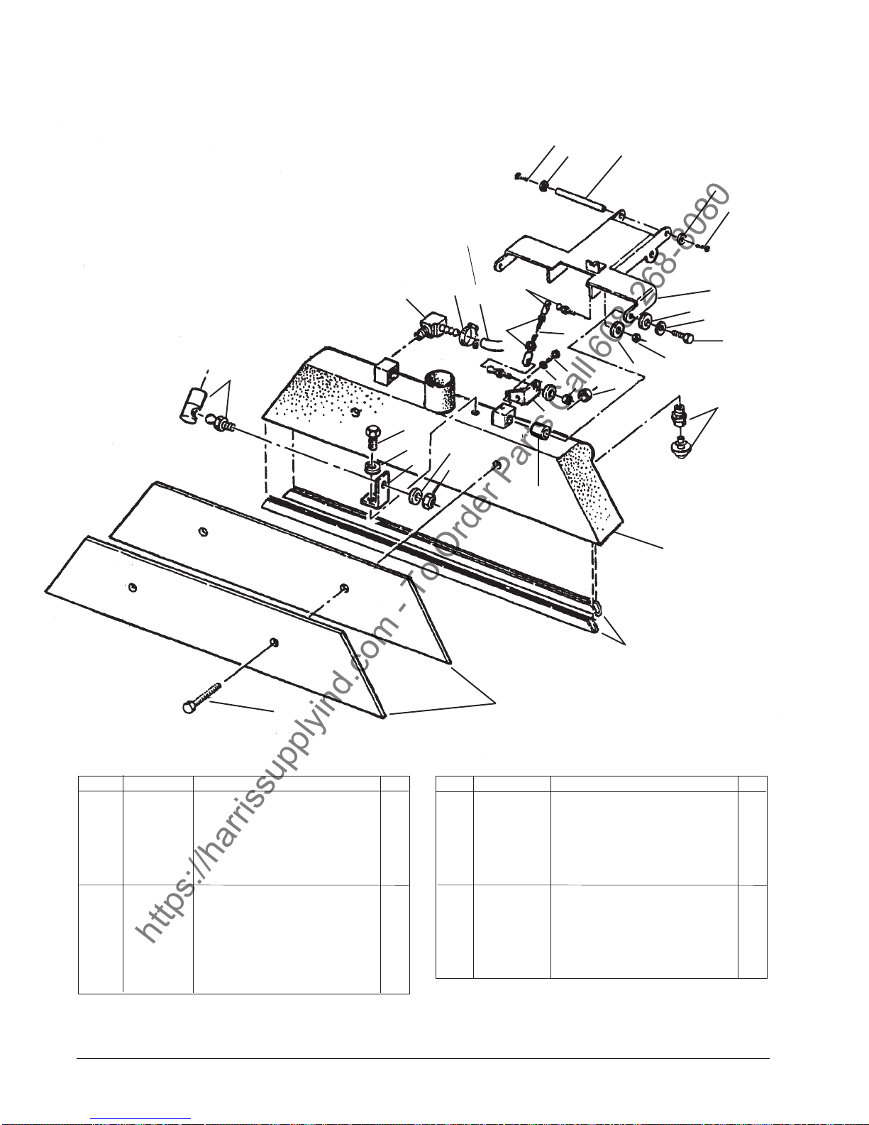
Clarke
https://harrissupplyind.com - To Order Parts Call 608-268-8080
Recovery Tool Assembly Drawing and Parts List 5/05
®
Image 26E
24
7
Page 28
D
From Solenoid
1
7
24
21
18
22
20
19
13
23
4
10
21
2
6
4
5
24
7
4
23
9
20
3
4
11
8
12
14
15
17
Ref Part No. Description Qty
1 67479A Shaft, Recovery Tool 1
2 63434A Lift, Recovery Weldment 1
3 962086 Screw, .25-20 x 2.00 Pan 2
4 81306A Nut, Hex 5/16-24 4
5 67164A Rod, Recovery Tool Adj. 1
6 87618A Washer, Nylon 2
7 980982 Washer, #10 Flat 4
8 65980A Bracket, Rec. Tool 1
9 920110 Nut, Lock 5/16-18 2
10 Ref. See page 23, #29 ref.
11 51320A Nozzle, Rinse 4
11a 52549A Nozzle, Rinse (Plasitc) 4
12 608210 Spacer 2
Page -32- Clarke® Operator's Manual IMAGE 26E
16
Ref Part No. Description Qty
13 50248A Clamp, Hose #6 1
14 27201A Shoe, Recovery 1
15 67619A Shoe, Recovery Tool 2
16 68808A Weight, Recovery Tool 2
17 85615A Screw, .31-18 x 1.25 Pn 2
18 732870 Elbow, 3/8 Barb x ¼ 1
19 61541A Bracket, Rec. Tool 1
20 980646 Washer, Flat 3
21 50546A Ball-Joint, Recovery Tool 3
22 962288 Screw 1
23 980652 Washer 3
24 170803 Screw, 10-24 x ½ 4
.
Page 33
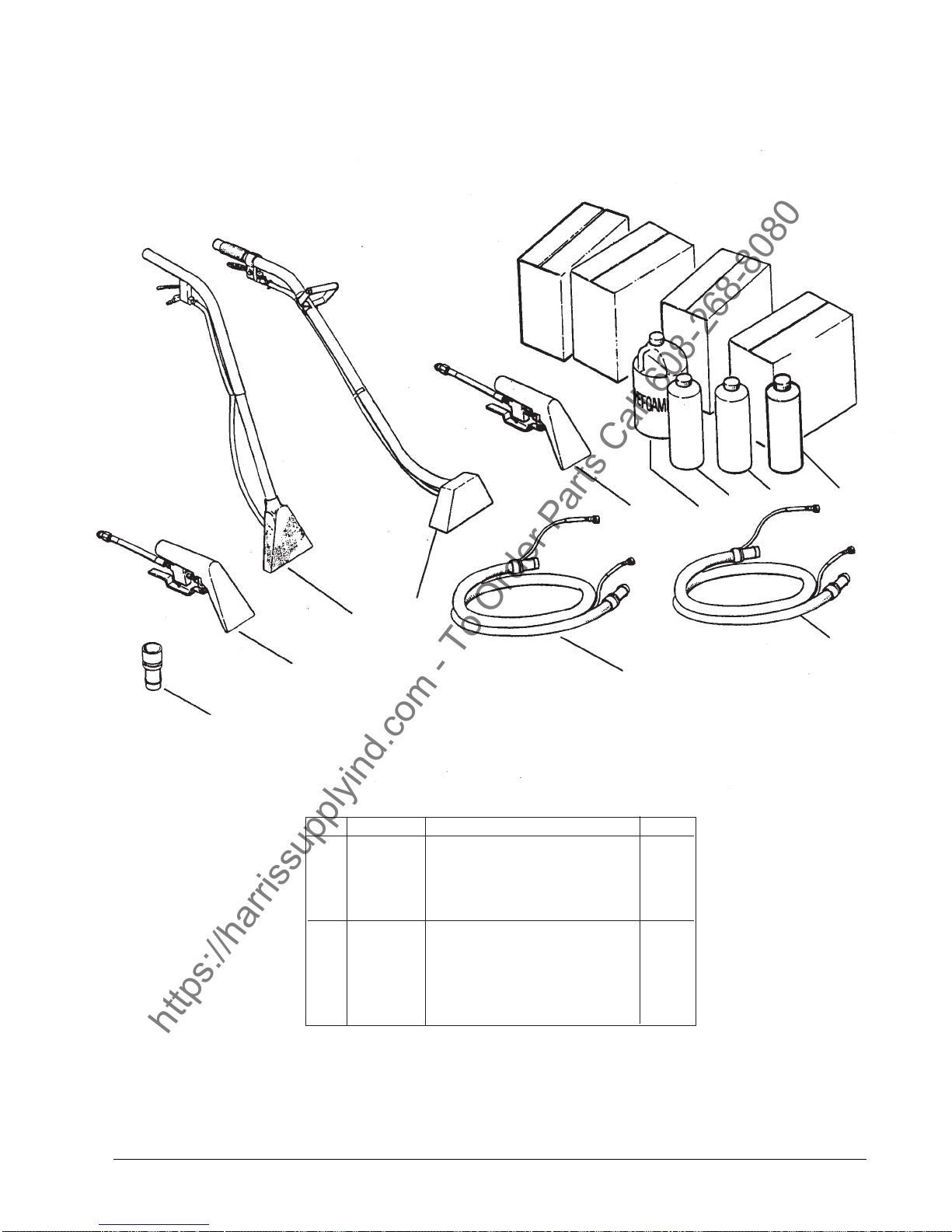
Clarke
https://harrissupplyind.com - To Order Parts Call 608-268-8080
Available Accessories 12/00
®
Image 26E
1**
6
3
2
Ref Part No. Description Qty
1 30108A Adaptor, 2" to 1½ 1
2 59231A RM-4P Tool Assembly 1
3 59230A RM-8P Tool Assembly 1
4 59229A RM-12M Tool Assembly 1
5 59232A Hide-A- Hose 10' 1
6 59228A RM-4M Tool Assembly 1
7 398426 Defoamer *1 case
8 398425 Extractor, Concentrate *1 case
9 398427 Traffic Lane/Spot Cleaner *1 case
10 55183A Hide-A-Hose 20' 1
11 52953A General Purpose Spot Cleaner 1 case
4
5
9
8
7
11
10
* 4, 1 gallon bottles
**Required to use any accessory
®
Clarke
Operator's Manual IMAGE 26E Page -33-
Page 34
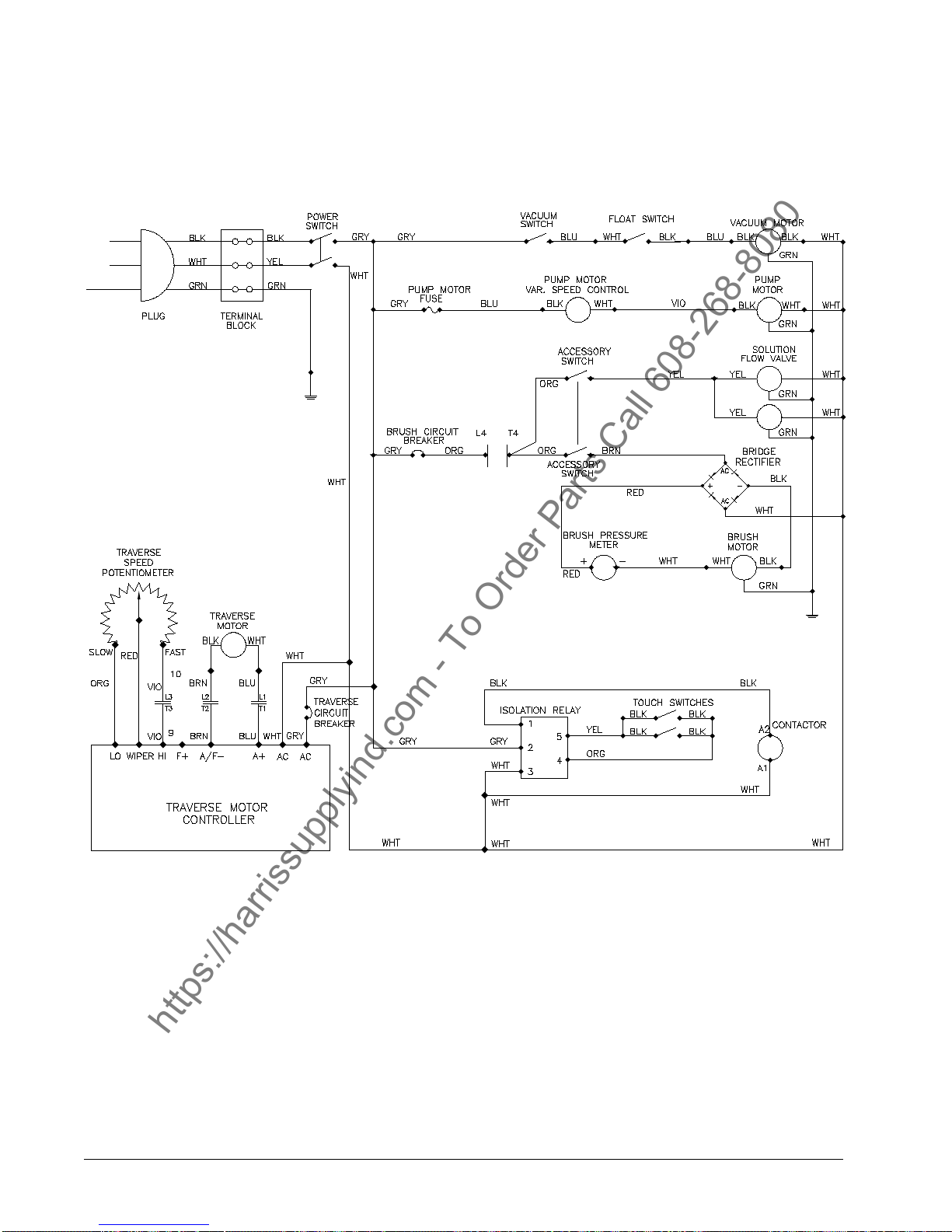
Clarke
https://harrissupplyind.com - To Order Parts Call 608-268-8080
Electrical Schematic 12/00
®
Image 26E
Page -34- Clarke® Operator's Manual IMAGE 26E
Page 35
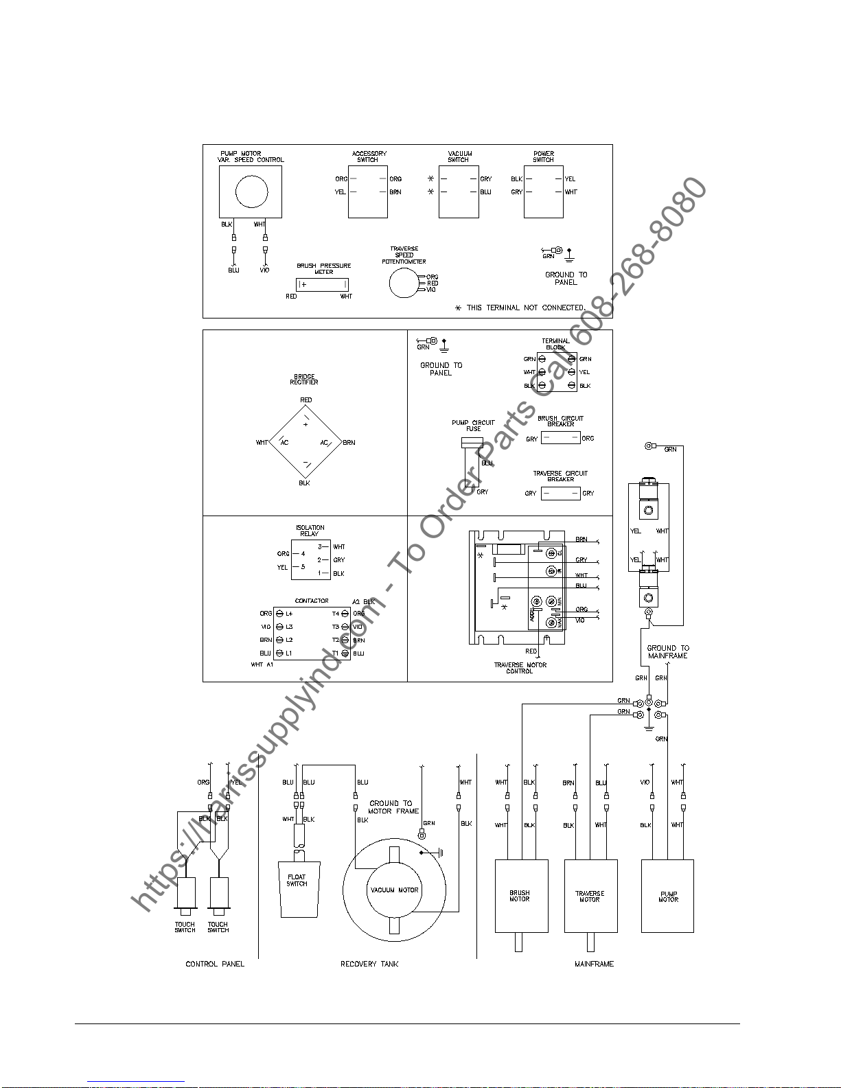
Clarke
https://harrissupplyind.com - To Order Parts Call 608-268-8080
Wiring Diagram 12/00
®
Image 26E
®
Clarke
Operator's Manual IMAGE 26E Page -35-
Page 36
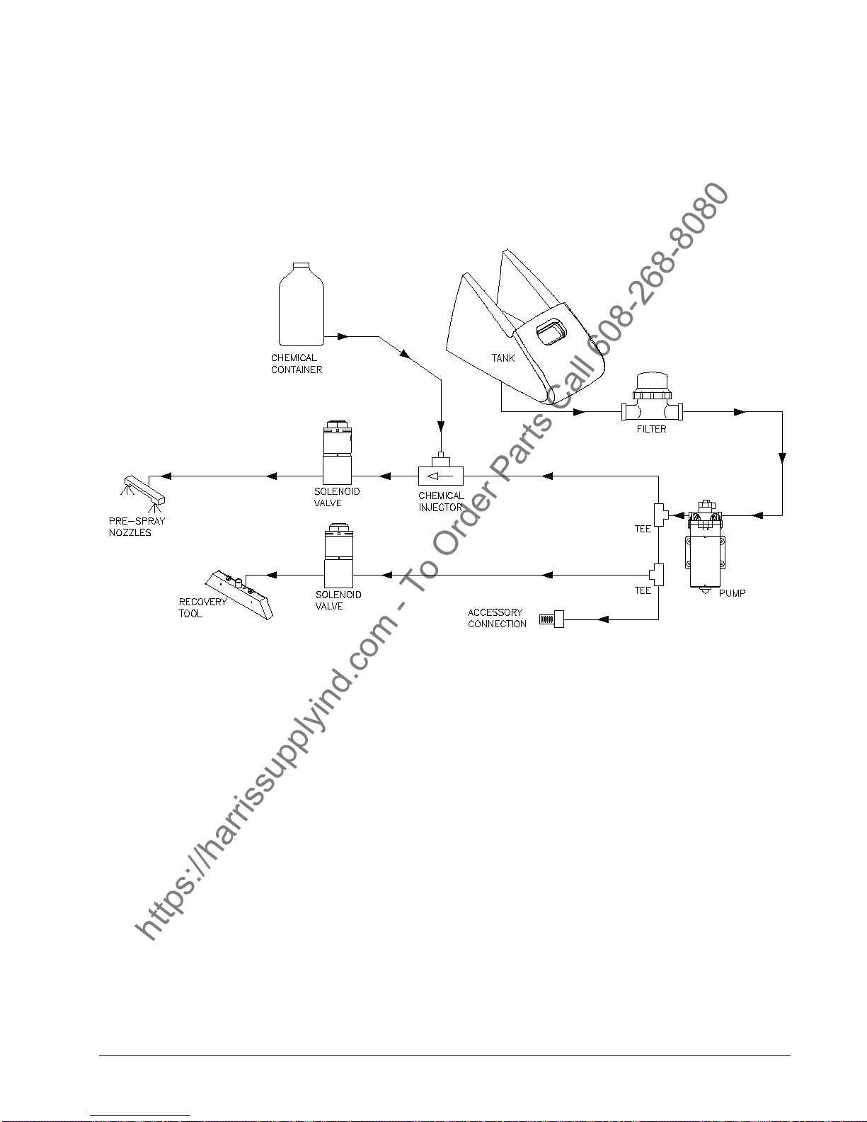
Clarke
https://harrissupplyind.com - To Order Parts Call 608-268-8080
Flow Diagram 12/00
®
Image 26E
Page -36- Clarke® Operator's Manual IMAGE 26E
Page 37

CLARKE PRODUCT SUPPORT BRANCHES
https://harrissupplyind.com - To Order Parts Call 608-268-8080
U. S. A. Locations European Locations
CORPO
PRODUCTION FACILITIES
®
Clarke
, Springdale, Arkansas
2100 Highway 265
Springdale, Arkansas 72764
(479) 750-1000
Customer Service - 1-800-253-0367
Technical Service - 1-800-356-7274
American Lincoln®, Bowling Green, Ohio 43402
1100 Haskins Road
SERVICE FACILITIES
Clarke®, Elk Grove, Illinois 60007
2280 Elmhurst Road
(847) 956-7900
Clarke®, Denver, Colorado 80204
1955 West 13th Ave.
(303) 623-4367
Clarke®, Houston, Texas 77040
7215 North Gessner Road
713-937-7717
PRODUCTION FACILITIES
ALTO Danmark A/S, Aalborg
Blytaekkervej 2
DK-9000 Aalborg
+45 72 18 21 00
ALTO Danmark A/S, Hadsund
Industrikvarteret
DK-9560 Hadsund
+45 72 18 21 00
SALES SUBSIDIARIES
Clarke® Canada Ltd., Rexdale Ontario
24 Constellation Ct.
(416) 675-5830
ALTO Overseas Inc., Sydney (Australia)
1B/8 Resolution Drive
Caringbah NSW 2229
+61 2 9524 6122
ALTO Cleaning Systems Asia Pte Ltd., Singapore
No. 17 Link Road
Singapore 619034
+65 268 1006
SERVICE AND SALES FACILITY
American Lincoln® / Clarke, Madison Heights,
Michigan 48071-0158
29815 John R.
(810) 544-6300
American Lincoln® / Clarke, Marietta, Georgia 30066
1455 Canton Road
(770) 973-5225
SALES AND DISTRIBUTION CENTER
Clarke®, Secaucus, NJ 07094
74 Henry Street
(201) 864-5503
Clarke
Clarke American Sanders
A.L. Cook
Customer Service Headquarters and Factory
2100 Highway 265
Springdale, Arkansas 72764
(479) 750-1000
Technical Service
1-800-356-7274
®
ALTO Deutschland GmbH, Bellenberg (Germany)
Guido-Oberdorfer-Straße 2-8
89287 Bellenberg
+49 0180 5 37 37 37
ALTO Cleaning Systems (UK) Ltd., Penrith
Gilwilly Industrial Estate
Penrith
Cumbria CA11 9BN
+44 1768 868 995
ALTO France S.A. Strasbourg
B.P. 44, 4 Place d’Ostwald
F-67036 Strasbourg
Cedex 2
+33 3 8828 8400
ALTO Nederland B.V.
Postbus 65
3370 AB Hardinxveld-Giessendam
The Netherlands
+31 184 677 200
ALTO Sverige AB, Molndal (Sweden)
Aminogatan 18
Box 4029
S-431 04 Molndal
+46 31 706 73 00
ALTO Norge A/S, Oslo (Norway)
Bjornerudveien 24
N-1266
+47 2275 1770
Page 38
Clarke
https://harrissupplyind.com - To Order Parts Call 608-268-8080
This Clarke Industrial/Commercial Product is warranted to be free from defects in materials and workmanship under
normal use and service for a period of one year from the date of purchase, when operated and maintained in accordance
with Clarke's Maintenance and Operations instructions.
This warranty is extended only to the original purchaser for use of the product. It does not cover normal wear parts such
as electrical cable, rubber parts, hoses and motor brushes.
If difficulty develops with the product, you should:
a). Contact the nearest authorized Clarke repair location or contact the Clarke Service Operations Department, 2100
Highway 265, Springdale, Arkansas 72764, for the nearest authorized Clarke repair location. Only these locations are
authorized to make repairs to the product under this warranty.
b). Return the product to the nearest Clarke repair location. Transportation charges to and from the repair location must be
prepaid by the purchaser.
c). Clarke will repair the product and or replace any defective parts without charge within a reasonable time after receipt
of the product.
Clarke's liability under this warranty is limited to repair of the product and/or replacement of parts and is given to
purchaser in lieu of all other remedies, including INCIDENT AL AND CONSEQUENTIAL DAMAGES.
THERE ARE NO EXPRESS WARRANTIES OTHER THAN THOSE SPECIFIED HEREIN. THERE ARE NO WARRANTIES WHICH
EXTEND BEYOND THE DESCRIPTION OF THE F ACE HEREOF . NO WARRANTIES, INCLUDING BUT NOT LIMITED TO WARRANTY OF MERCHANTABILITY, SHALL BE IMPLIED. A warranty registration card is provided with your Clarke product.
Return the card to assist Clarke in providing the performance you expect from your new floor machine.
Clarke
®
, 2100 Highway 265, Springdale, Arkansas 72764.
®
LIMITED U.S. WARRANTY
Clarke
®
POLYDUR
®
TANK
EIGHT-YEAR GUARANTEE
Your new Image Carpet Extractor has a polydur Solution and Recovery Tanks. Polydur is a rotationally molded, lowdensity linear polyethylene that won't crack or dent, and withstands most corrosives and temperature extremes. Clarke
backs up your Polydur tanks with an eight-year guarantee. If a tank breaks, cracks or leaks under normal use within eight
years of the date of purchase, it will be replaced free.
Clarke reserves the right to make
changes or improvements to its machine without notice.
Always use genuine Clarke Parts for repair.
2100 Highway 265
Springdale, Arkansas, 72764
 Loading...