

Page 1
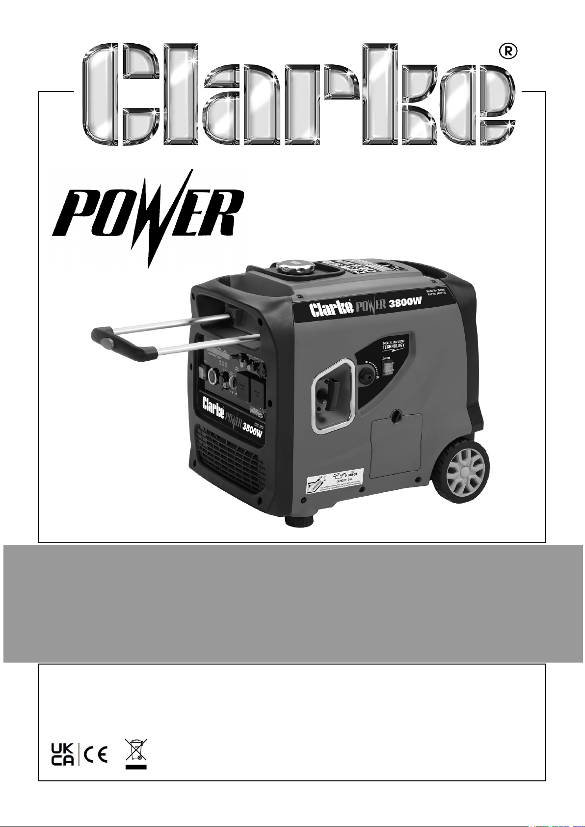
3.8KW INVERTER GENERATOR
MODEL NO: IG4000
PART NO: 8877130
OPERATION & MAINTENANCE
INSTRUCTIONS
ORIGINAL INSTRUCTIONS DL1124 Rev 2
Page 2

INTRODUCTION
Thank you for purchasing this CLARKE Generator.
Before attempting to operate the machine, it is essential that you read this manual
thoroughly and carefully follow all instructions given. In doing so you will ensure the
safety of yourself and that of others around you, and you can also look forward to the
product giving you long and satisfactory service.
Ensure the generator and its components suffered no damage during transit and that
all components are present. Should any loss or damage be apparent, please contact
your CLARKE dealer immediately.
GUARANTEE
This CLARKE product is guaranteed against faulty manufacture for a period of 12
months from the date of purchase. Please keep your receipt as proof of purchase.
This guarantee is invalid if the product is found to have been abused or tampered
with in any way, or not used for the purpose for which it was intended.
Faulty goods should be returned to their place of purchase, no product can be
returned to us without prior permission.
This guarantee does not effect your statutory rights.
2
Parts & Service: 020 8988 7400 / E-mail: [email protected] or [email protected]
Page 3
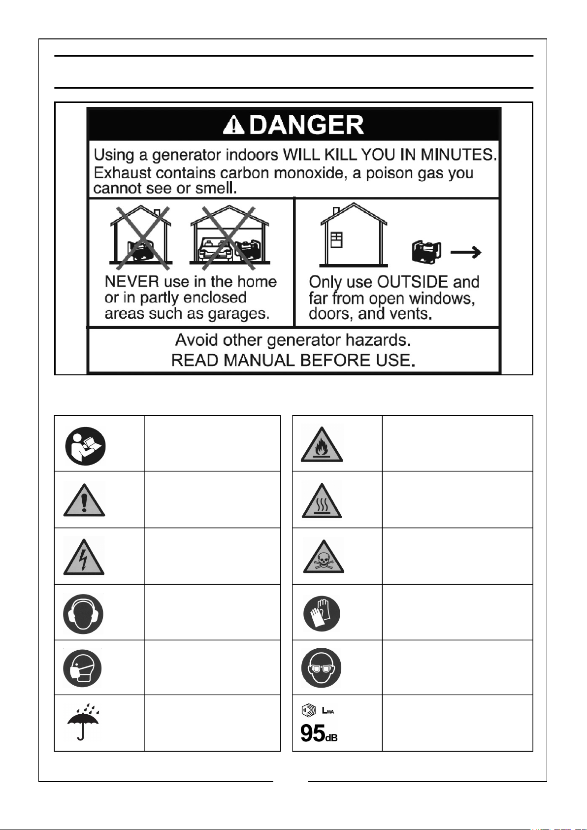
GENERAL SAFETY RULES & SYMBOLS
SAFETY SYMBOLS
Read Instruction
manual before use
Caution - The user
should be aware of a
general hazard
Dangerous voltage.
Risk of electric shock
Wear ear defenders Wear protective gloves.
Wear a protective
face-mask.
DANGER - highly
flammable liquid.
Engine and exhaust
become hot during use DO NOT touch
Poisonous fumes - DO
NOT use in an enclosed
space.
Wear eye protection
DO NOT use in rain,
snow or damp
conditions.
3
Parts & Service: 020 8988 7400 / E-mail: [email protected] or [email protected]
WARNING: Loud
noise.
Page 4

WORK AREA
1. ALWAYS use in a well ventilated area.
2. ALWAYS position the exhaust outlet away from people.
3. NEVER use indoors or in a confined space.
4. ALWAYS keep children away from the generator.
POSITIONING THE GENERATOR
1. ALWAYS leave a least a 1m gap between the generator and any surrounding
building or structures.
2. ALWAYS ensure the generator is on a dry, solid, level and flat surface.
3. ALWAYS ensure the surrounding area is free from any material that could burn or
be damaged by heat.
4. NEVER move or tilt the generator whilst it is switched on.
FIRE PREVENTION
1. ALWAYS switch the engine OFF when refuelling. Allow generator to cool for at
least 2 minutes before removing the fuel cap. Loosen cap slowly to relieve
pressure in the tank.
2. ALWAYS refuel away from any source of heat.
3. ALWAYS refuel in a well ventilated area.
4. ONLY use standard unleaded petrol.
5. DO NOT overfill the fuel tank. DO NOT fill to the very top of the tank and leave
room for petrol expansion.
6. NEVER smoke whilst refuelling and avoid smoking or using a naked flame near
the generator.
7. DO NOT operate near an open flame, heat or flammable materials. This
generator may emit highly flammable and explosive petrol vapours.
8. NEVER start the engine if there is spilled fuel. Any spillage must be wiped clean
and the generator allowed to dry before attempting to start the engine.
PREVENTION OF ELECTRIC SHOCK
1. NEVER use the generator in wet conditions unless it is well protected/covered.
Under these conditions, adequate ventilation MUST be provided.
2. NEVER operate the generator with wet hands.
3. NEVER use water or any other liquids to clean the generator.
4
Parts & Service: 020 8988 7400 / E-mail: [email protected] or [email protected]
Page 5

4. ALWAYS ground the generator before using it to maximise safety, see ‘Ground
The Generator’ section on pages 15-16.
5. ALWAYS use a ground fault circuit interrupter (GFCI) in highly conductive areas
such as metal decking or steel work. Extension cords with an in-line GFCI are
recommended for these operations.
ADDITIONAL SAFETY RULES FOR GENERATORS
1. ALWAYS ensure the applied load does not exceed the generator rating.
Overloading the generator is dangerous and could cause damage.
ALWAYS
2.
maintenance.
3. ALWAYS ensure the generator reaches operating speed before connecting a
load.
4. NEVER allow the generator to run out of fuel when a load is connected.
5. NEVER transport the generator with fuel in the tank.
6. DO NOT connect to a commercial or residential power supply; e.g. ring main.
disconnect and switch off the generator when carrying out any
7. DO NOT touch hot parts. This generator produces heat when running.
Temperatures near the exhaust can exceed 150°F/65°C. Allow the generator to
cool down after use before touching the engine or areas of the generator that
become hot during use.
8. If any part of the generator, electrical device or power cable is broken, damaged
or defective, make sure it is repaired or replaced before using. Service or repair of
the generator should only be performed by a qualified technician.
9. NEVER modify the generator in any way. Modifying or using the generator for any
other purpose for which it is not designed may result in serious injury, machine
damage and voiding of the warranty.
10. ALWAYS turn off all connected electrical devices before stopping the generator.
11. ALWAYS turn the engine switch to the ‘OFF’ position when the engine is not
running.
12. NEVER carry or lift the generator using the telescopic handle.
5
Parts & Service: 020 8988 7400 / E-mail: [email protected] or [email protected]
Page 6
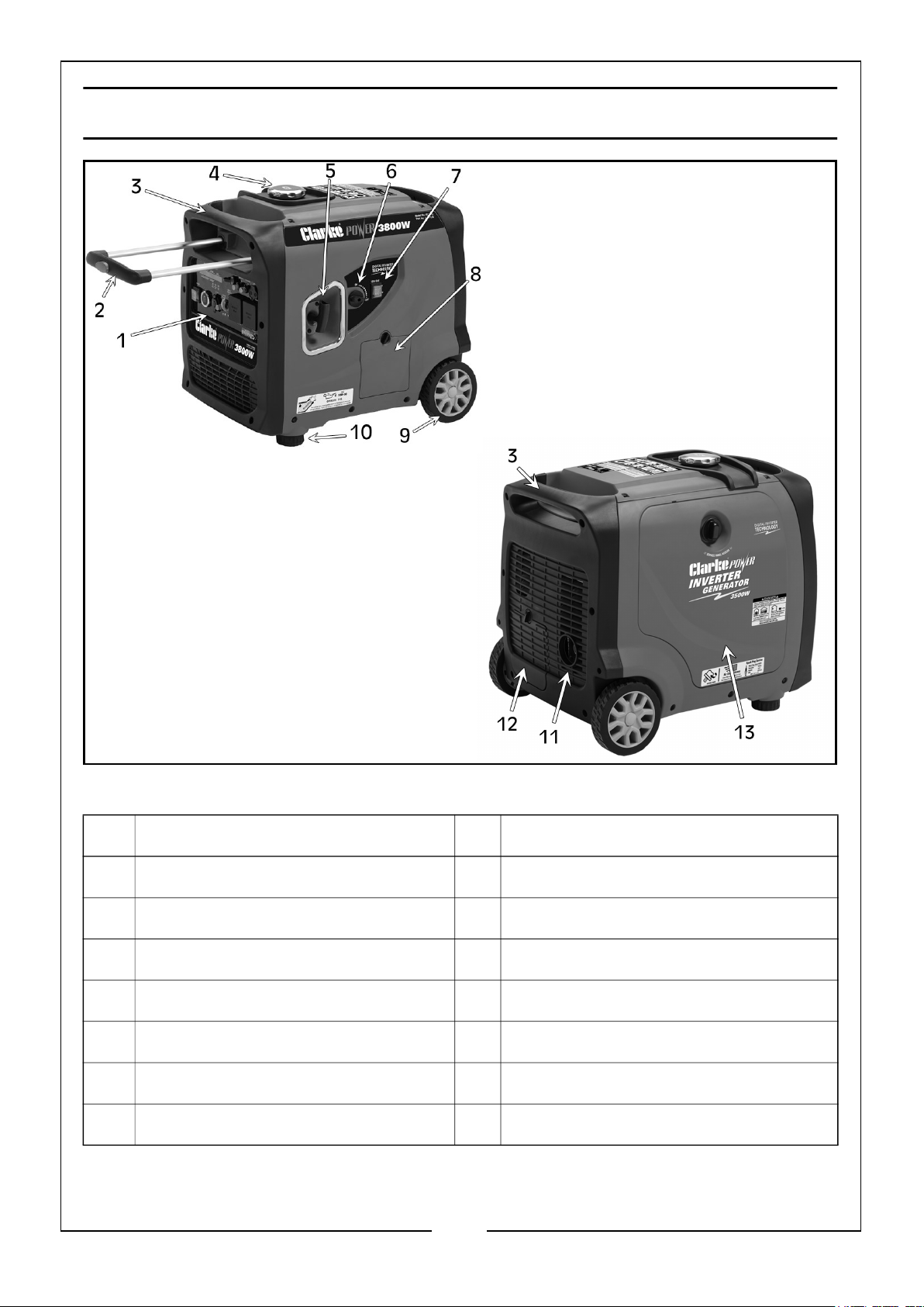
GENERATOR OVERVIEW
NO DESCRIPTION NO DESCRIPTION
1 Control Panel 8 Oil Access Cover
2 Telescopic Handle 9 Wheel
3 Carrying Handle 10 Foot
4 Fuel Cap 11 Exhaust/Muffler
5 Recoil Starter 12 Battery Access Cover
6 Low Idle Mode Switch 13 Engine Maintenance Cover
7 Fuel Switch
6
Parts & Service: 020 8988 7400 / E-mail: [email protected] or [email protected]
Page 7
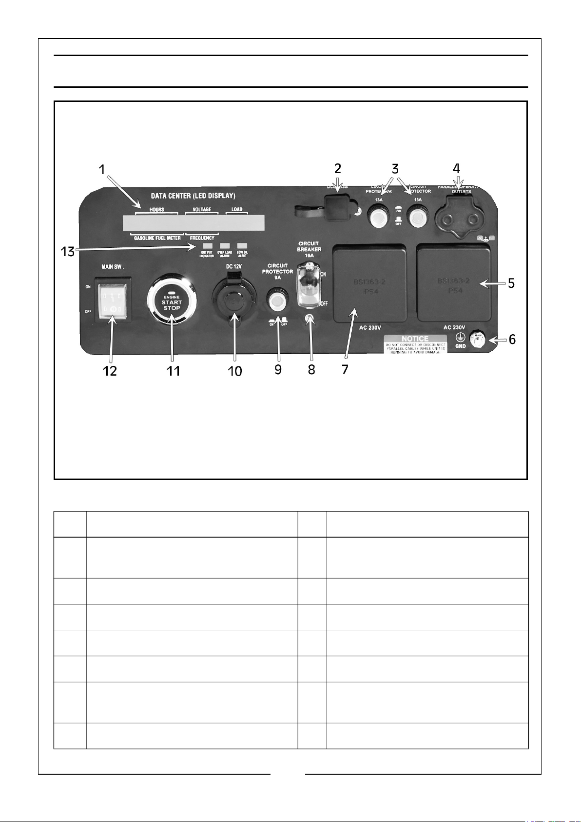
CONTROL PANEL OVERVIEW
NO DESCRIPTION NO DESCRIPTION
1 Fuel Gauge, Voltage & Load
Display
2 5V DC USB Outlet 9 9A Circuit Protector
3 13A Circuit Protectors 10 12V DC Power Outlet
4 Parallel Operation Outlet 11 Engine STOP/START Button
5 AC 230V 3 Pin Plug Outlet 12 Main SW Switch ON/OFF Button
6 Ground Earthing Point 13 Output, Overload Alarm & Low Oil
7 AC 230V 3 Pin Plug Outlet
Parts & Service: 020 8988 7400 / E-mail: [email protected] or [email protected]
8 16A Circuit Breaker
Alert Indictors
7
Page 8
UNPACKING
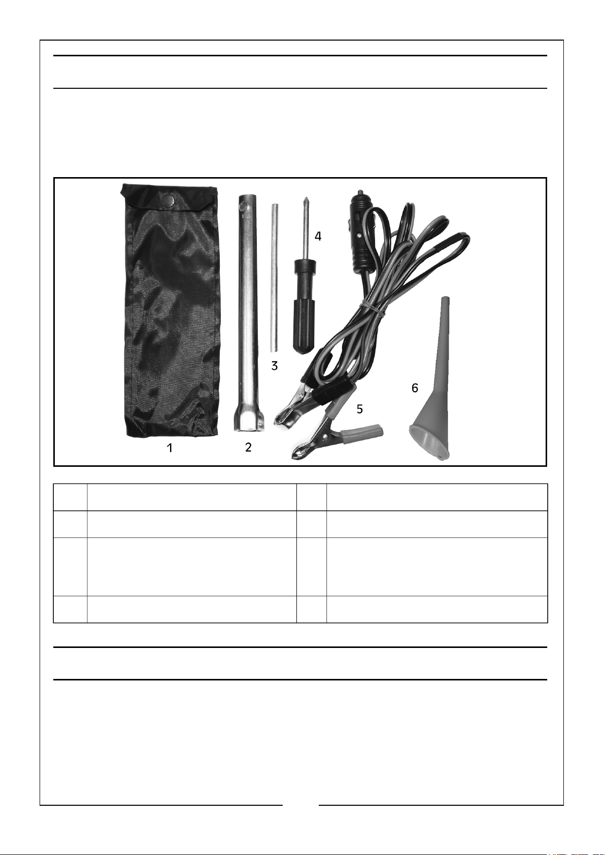
Unpack your generator and check to ensure the following items are present.
Should there be any deficiency or damage caused during transit contact your
CLARKE dealer immediately.
NO DESCRIPTION NO DESCRIPTION
1 Tool Pouch 4 Cross Head Screwdriver
2 Spark Plug Spanner 5 12 Volt D.C. output lead assembly
with positive (red, ‘+’) and negative
(black ‘-’) crocodile clips
3 Spark Plug Spanner Arm 6 Oil Funnel
BEFORE USING THE GENERATOR
Before using your generator check that:
• The generator is in good condition and free from any damage.
• The generator is clean and free from fuel or oil spillage.
• The generator is correctly located for use.
8
Parts & Service: 020 8988 7400 / E-mail: [email protected] or [email protected]
Page 9
KNOW YOUR GENERATOR
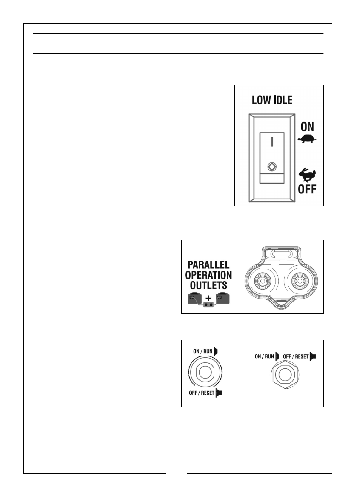
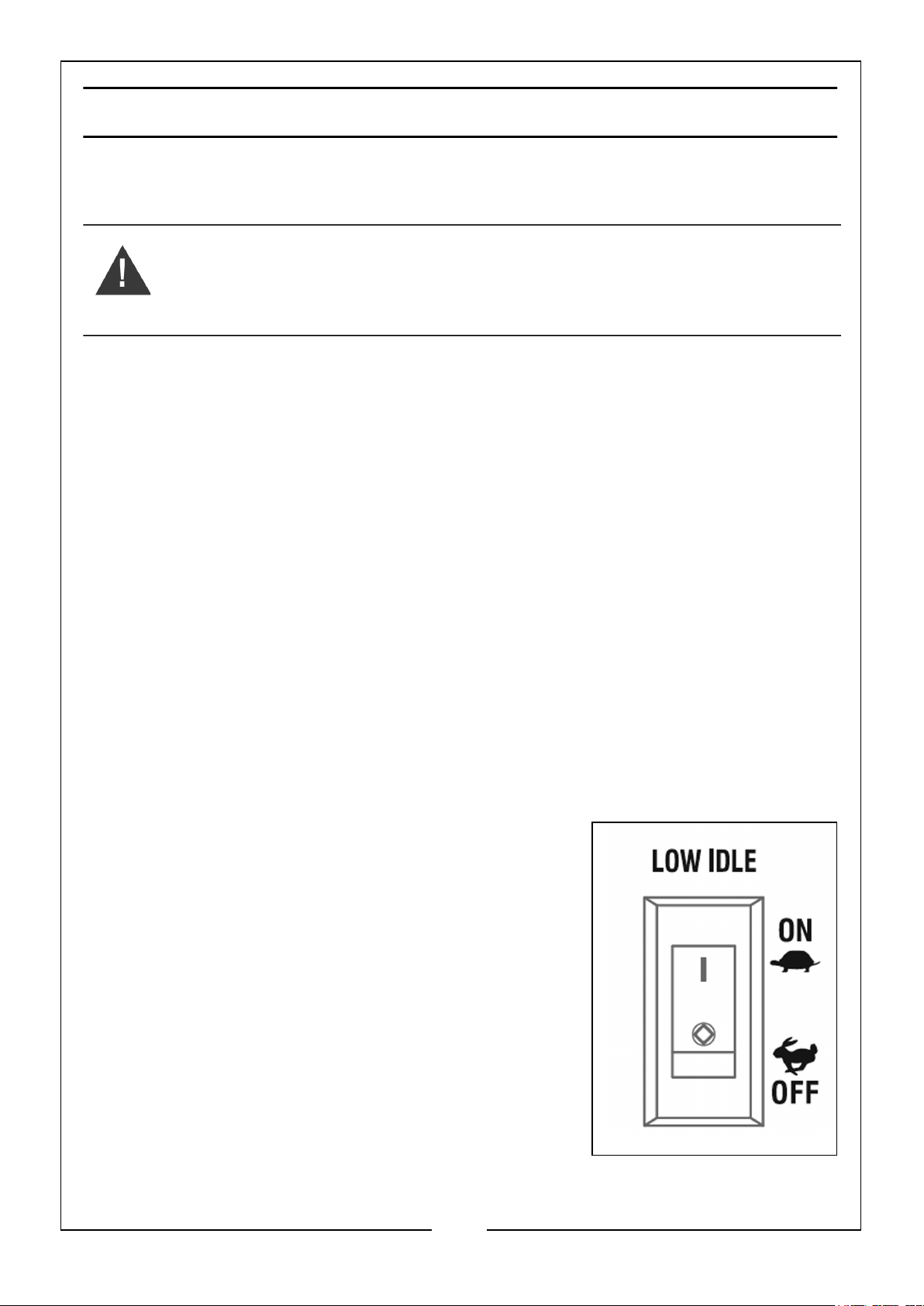
LOW IDLE
This generator is equipped with a low idle switch.
Engaging this switch allows the system to regulate the
engine speed and automatically adjust its fuel
consumption to match the required load. When the
electrical load changes, the generator engine will
automatically speed up and slow down as needed. This
reduces fuel consumption and noise levels, while
extending runtime and the engines lifespan.
Keep this switch engaged (ON) only when the power load
requirement is less than 75% of the rated watts. DO NOT
engage the switch when the total load is more than 75%
of rated watts. The generator engine must run at full
speed to supply power for anything over 75% of rated
watts.
PARALLEL OPERATION
The parallel operation outlet allows you to
connect two of these generators together
to increase the total available electrical
power. Follow the instructions included
with the parallel operation kit (not
included) for correct installation and
operation.
CIRCUIT BREAKERS
The circuit breakers protect the individual
AC and DC circuits. The AC circuit breaker
will activate when the AC outlets exceed
their maximum current. The DC circuit
breaker will activate when the DC 12V
and/or USB outlet exceed their maximum
current. When the circuit breaker
activates, turn off and disconnect the
device(s) from the respective outlets and press the circuit breaker to reset.
9
Parts & Service: 020 8988 7400 / E-mail: [email protected] or [email protected]
Page 10
CONNECTING ELECTRICAL DEVICES
Follow the steps below to properly connect your device(s) to the generator.
1. Before connecting electrical devices, allow the generator to run for a few minutes
to stabilise the speed and voltage output.
2. Select the device with the highest wattage, and make sure it is turned off. Plug the
device into the generator and then turn the device on. Allow the engine to
stabilise.
3. Repeat step 2 to plug in each additional device. DO NOT attempt to plug in and
start multiple devices at the same time.
GENERATOR CAPACITY
Make sure the generator can supply enough running (rated) and starting (max.) watts
for the items you will power at the same time. Follow these simple steps.
1. Select the items you will power at the same time.
2. Total the running (rated) watts of these items. This is the amount of power the
generator must produce to keep the items running.
3. Estimate how many starting (max.) watts you will need. Starting wattage is the
short burst of power needed to start electric motor driven tools such as a circular
saw or refrigerator. Because not all motors start at the same time, total starting
(max.) watts can be estimated by adding only the items with the highest
additional starting (max.) to the total rated watts.
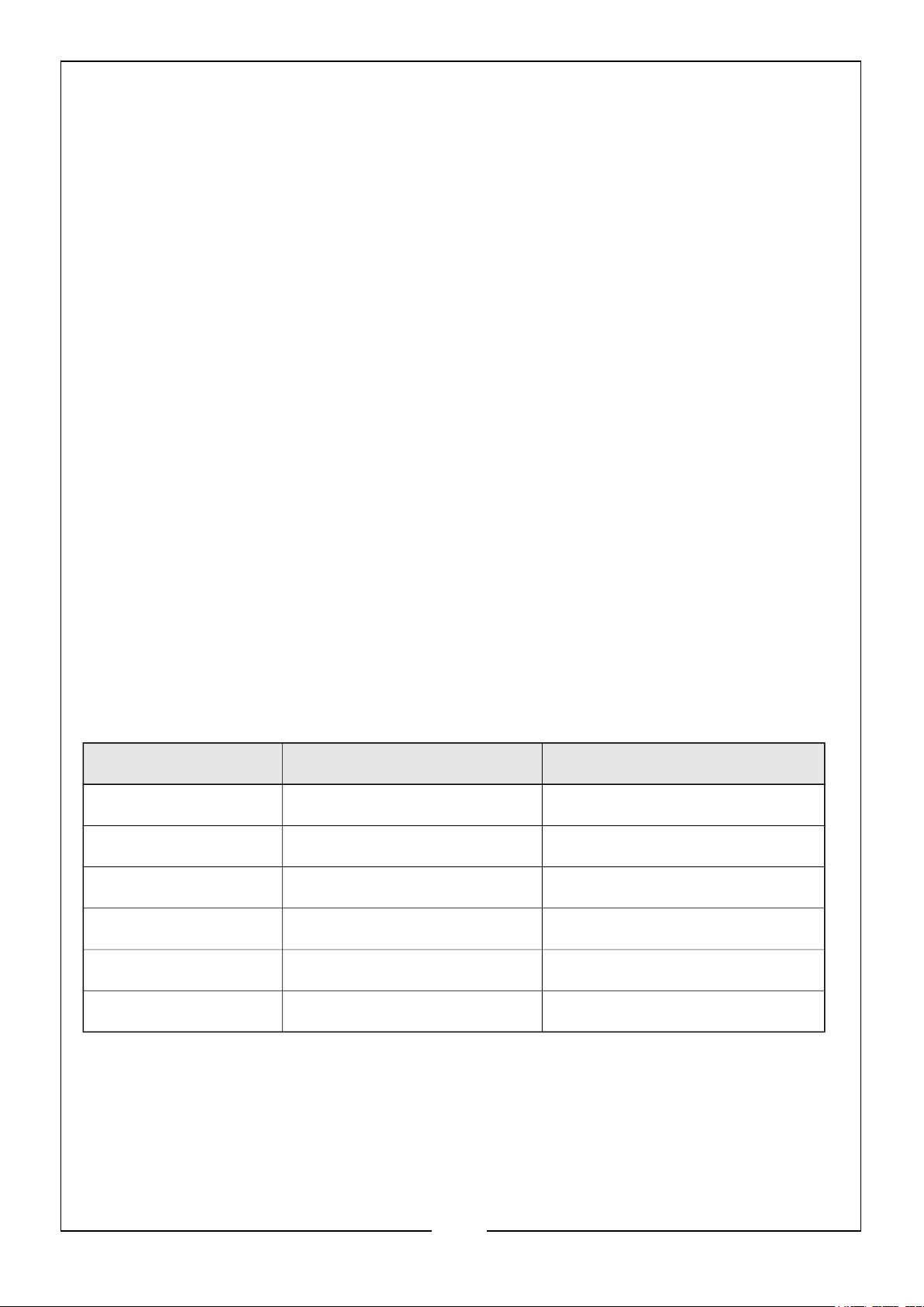
Example:
Tool/Appliance Running Watts Additional Starting Watts
Refrigerator 700 1350
Portable Fan 40 120
Laptop 250 250
46 in. Flat Screen TV 190 190
Light (75 Watts) 75 75
1255 Total Running Watts 1350 Highest Starting Watts
Total Running Watts: 1255
Highest Starting Watts: +1350
Total Starting Watts Needed = 2605
10
Parts & Service: 020 8988 7400 / E-mail: [email protected] or [email protected]
Page 11
NEVER add more loads than the generator capacity. Take special care to consider
surge loads in generator capacity as previously described.
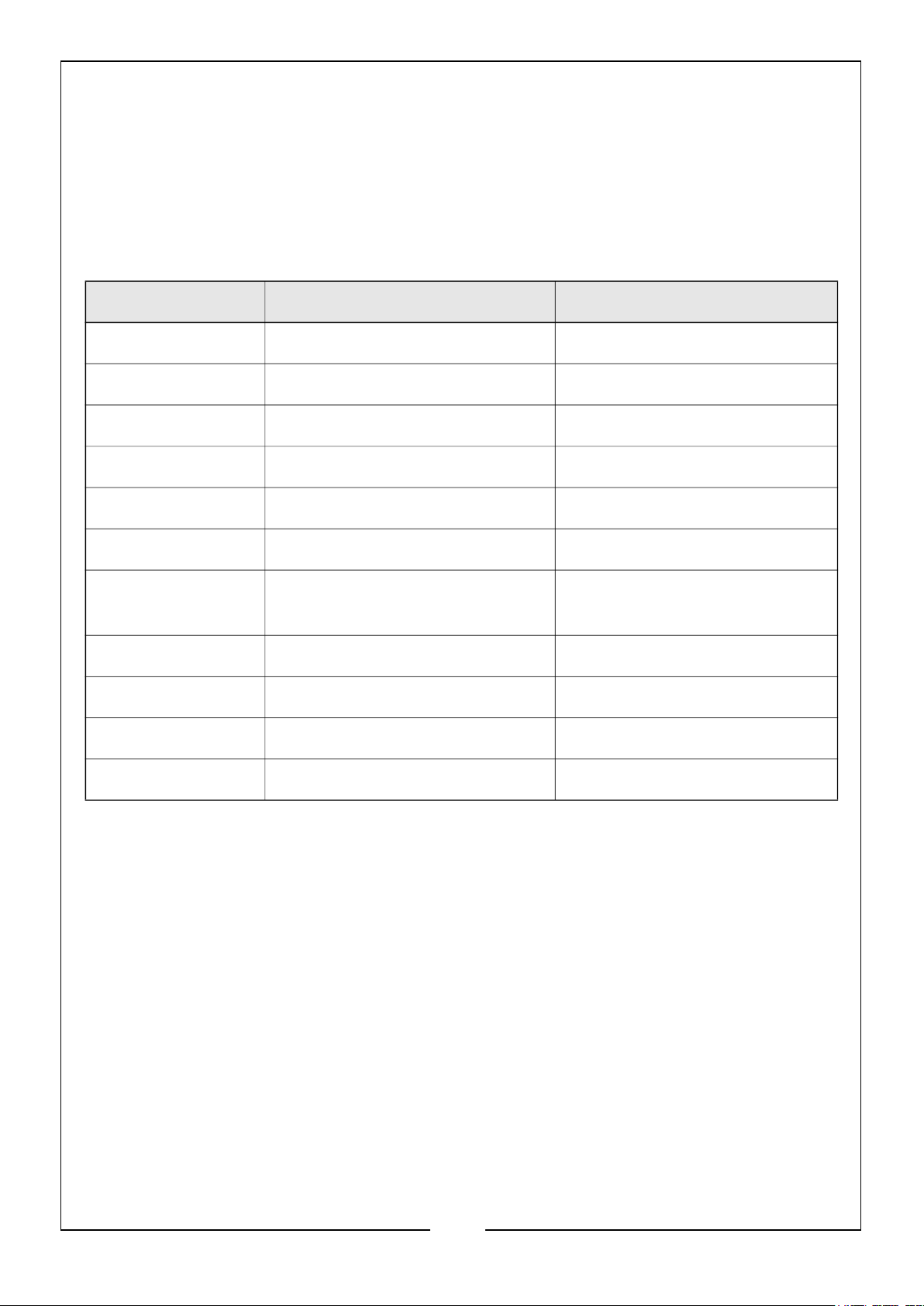
The chart below serves as a reference for the estimated wattage requirements of common electrical devices. however, DO NOT solely reply on this chart, all electronics and
appliances are built differently, ALWAYS check the wattage listed on the electrical
device before consulting this chart:
Tool/Appliance Rated (Running) Watts Surge (Starting) Watts
Hot Plate 2500 0
Saw - Circular 1500 1500
Saw - Mitre 1200 1200
Microwave 1000 0
Well Water Pump 1000 1000
Sump Pump 800 1200
Refrigerator
800 1200
Freezer
Computer 800 0
Television 500 0
Box Fan 300 600
Light Bulb 75 0
11
Parts & Service: 020 8988 7400 / E-mail: [email protected] or [email protected]
Page 12
GENERATOR PREPARATION
STEP 1 - ADD/CHECK OIL
NOTE: THE GENERATOR IS SHIPPED WITHOUT OIL ADDED.
The user must add the proper amount of oil before operating the generator for the first
time. The oil capacity of the engine crankcase is 0.6l (20.2 fl.oz).
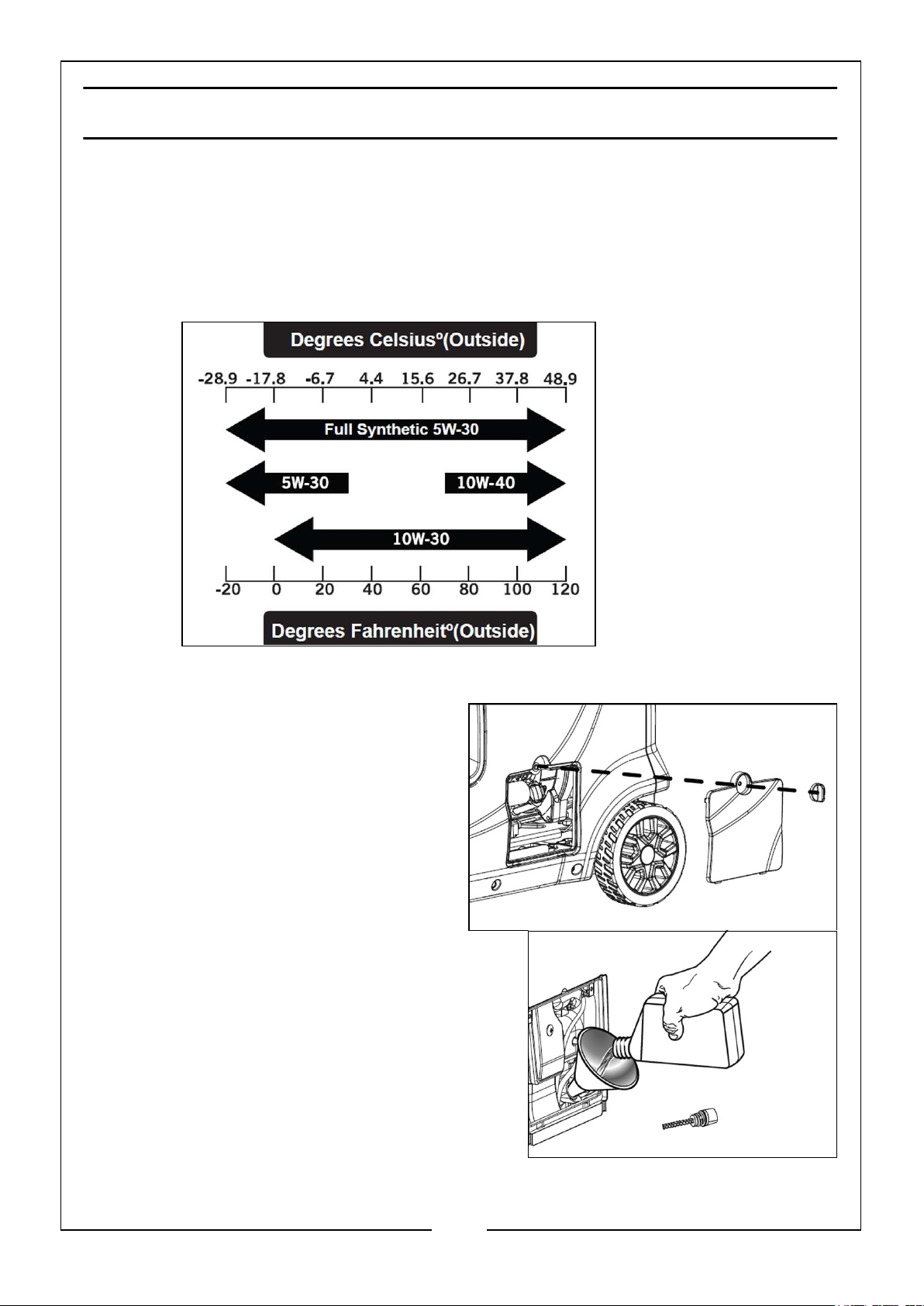
NOTE: Depending on
outside working
temperature, to find
out which oil to use,
consult the chart
shown.
To add oil, follow these steps:
1. Place the generator on a level
surface. make sure the engine is OFF
before adding or checking oil.
2. Unscrew the oil access cover knob
and remove the cover from the side
panel, as shown. Unscrew the yellow
oil dipstick from the engine.
3. Using the oil funnel or appropriate
dispenser, slowly add oil into the oil fill, as
shown, being careful not to overfill the unit.
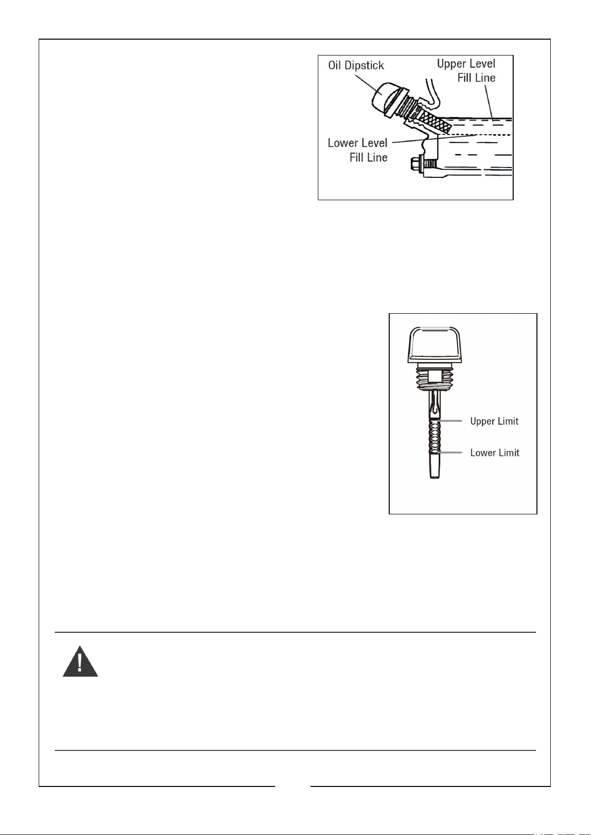
Fill the crankcase to the upper fill line so you
can visually see the oil coming halfway up
the oil fill threads.
4. Reinstall the oil dipstick and firmly tighten it.
Wipe clean any spilled oil.
12
Parts & Service: 020 8988 7400 / E-mail: [email protected] or [email protected]
Page 13
NOTE: Used engine oil should be
disposed of at an approved
disposal site. See local authority
recycling for more information.
For subsequent operation, the oil level should be checked before each use, or after
every 8 hours of operation. The generator is equipped with a low oil sensor and will not
start without a sufficient amount of oil.
TO CHECK OIL LEVEL (BEFORE EVERY SUBSEQUENT START)
1. Place the generator on a level surface. Make sure the
engine is OFF before adding or checking oil.
2. Open the oil access cover. Remove and wipe the
dipstick with a clean rag.
3. Insert the dipstick into the oil fill without screwing it in.
Remove the dipstick and check the oil mark.
4. If the oil mark covers less than one half of the dipstick,
slowly add oil until the oil mark reaches to the top of
the dipstick (or when you can see the oil coming
halfway up the oil fill threads).
5. Wipe clean any oil leaks and firmly tighten the dipstick.
Reinstall the oil access cover.
STEP 2 - ADD/CHECK FUEL
Use only fresh (within 30 days from purchase), lead-free petrol with a minimum of 87
octane rating. the generator performs best with ethanol-free petrol. DO NOT use petrol
with over 10% ethanol. The capacity of the fuel tank is 10Litres
(2.6 gallons). DO NOT MIX OIL WITH THE PETROL.
WARNING: KEEP GENERATOR AWAY FROM OPEN FLAME. THIS
GENERATOR MAY EMIT HIGHLY FLAMMABLE AND EXPLOSIVE
PETROL VAPOUR, WHICH CAN CAUSE SEVERE BURNS OR EVEN
DEATH IF IGNITED. A NEARBY OPEN FLAME CAN LEAD TO
EXPLOSION EVEN IF NOT DIRECTLY IN CONTACT WITH THE
PETROL.
13
Parts & Service: 020 8988 7400 / E-mail: [email protected] or [email protected]
Page 14
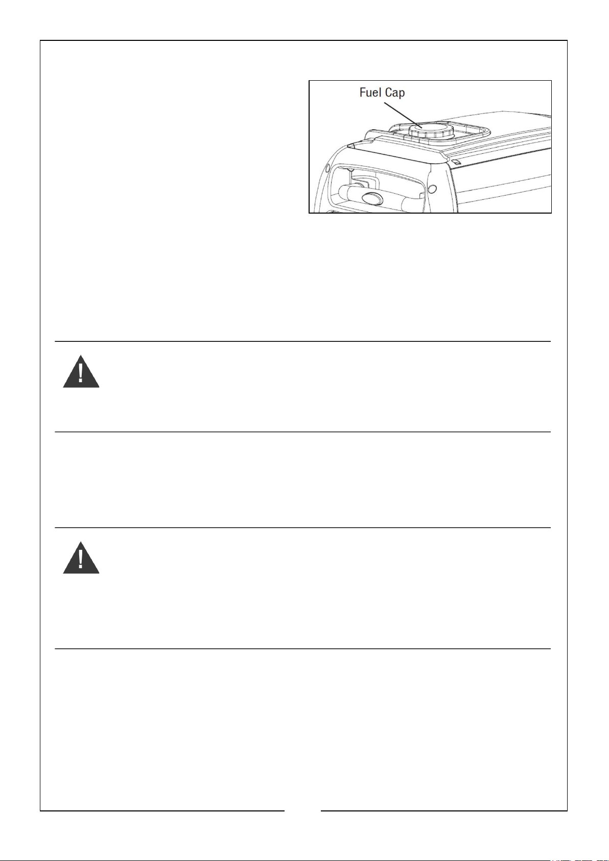
To add petrol, follow these steps:
1. Make sure the generator is shut OFF
and on a level surface. Unscrew the
fuel cap, as shown, and set it aside.
The fuel cap may be tight and hard to
unscrew.
2. Slowly add unleaded petrol to the
fuel tank. Be careful not to overfill.
NOTE: DO NOT fill the fuel tank to
the very top. If you do so,
petrol will expand and spill during use, even with the fuel cap in place.
3. Reinstall the fuel cap and wipe clean any spilled petrol with a dry cloth.
NOTE: During operation, the fuel level will be displayed on the data centre of
the control panel, or check the fuel gauge. If the fuel level is low, refill
the fuel tank before starting your generator for the next time.
WARNING: ENSURE THERE IS ADEQUATE FUEL IN THE TANK WHEN
USING THE GENERATOR. RUNNING OUT OF FUEL OR STOPPING THE
ENGINE SUDDENLY WITH A LOAD CONNECTED COULD CAUSE
SERIOUS DAMAGE.
STEP 3 - CONNECT THE BATTERY
The generator is shipped with the lithium-ion battery’s connection cables disconnected
to maximise safety. To start the generator using the electric start, the battery must be
connected.
CAUTION: ALWAYS USE EYE PROTECTION WHEN HANDLING
BATTERIES AND WASH YOURS HANDS AFTER HANDLING.
• Keep battery away from sparks, cigarettes or other sources of flame.
• Connect & disconnect battery only when generator is OFF and in well
ventilated areas.
• Keep out of reach of children.
To connect the battery, follow these steps:
14
Parts & Service: 020 8988 7400 / E-mail: [email protected] or [email protected]
Page 15
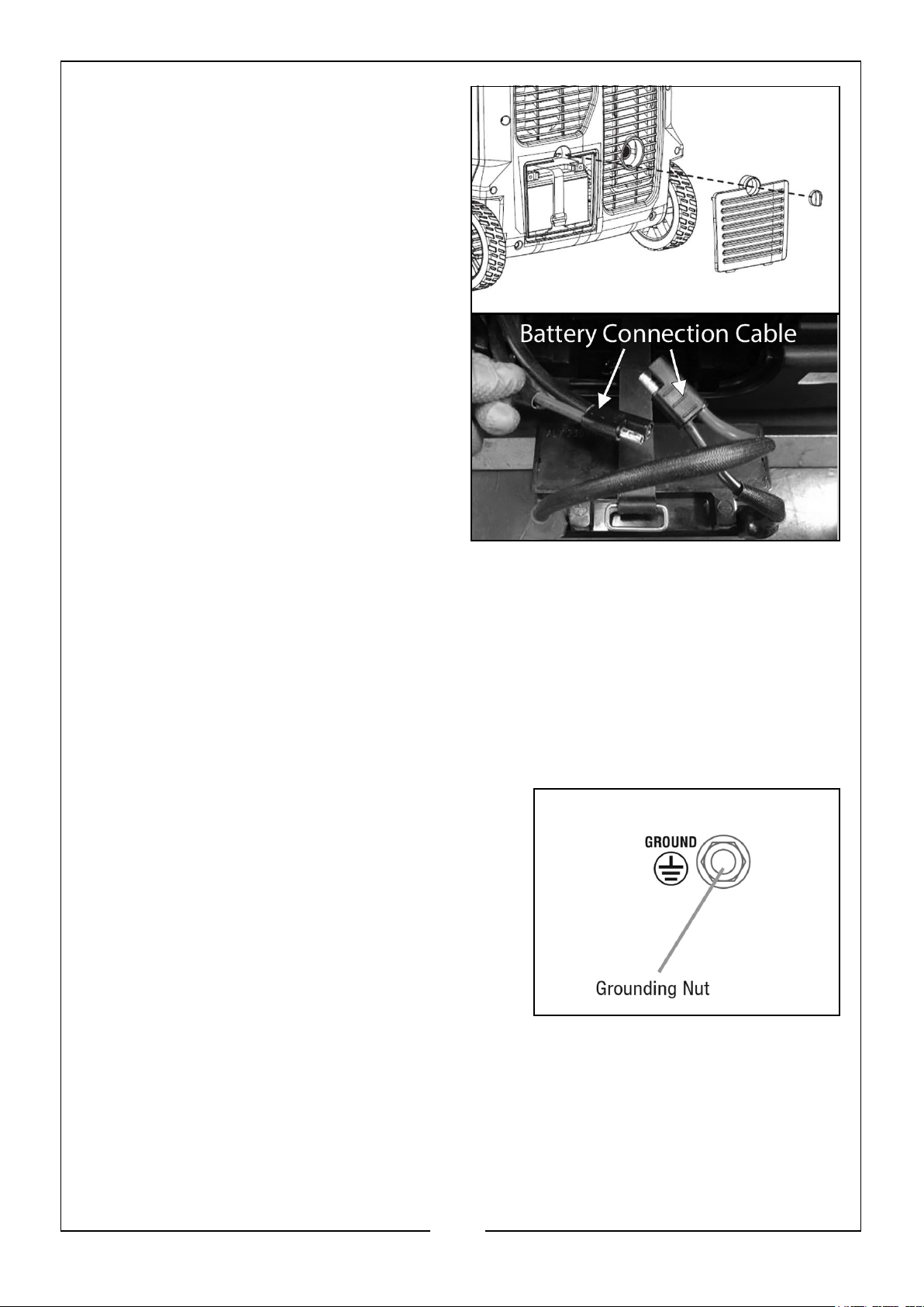
1. Turn the battery cover knob to the
unlocked position, and remove the
access cover from the back panel.
2. Loosen the rubber belt holding the
battery in position and pull out the
battery.
3. Push the two connectors together,
making sure the red and the black
cable connectors match up and are a
secure fit.
4. Return the battery into position and
use the rubber belt to fasten the
battery in place.
5. Reinstall and secure the battery
access cover.
NOTE: If you do not plan to use the generator for a long period of time, we
recommend to disconnect the battery cable from the battery to protect
the battery from losing charge. You may also choose to use a trickle
charger (not included) to maintain battery charge.
STEP 4 - GROUND THE GENERATOR
To reduce the risk of electric shock and to maximise safety, the generator should be
properly grounded.
Ground the generator by tightening the ground
nut on the front control panel, as shown, against a
grounding wire. A generally acceptable grounding
wire is a No. 14 SWG (Standard Wire Gauge)
stranded copper wire.
This grounding wire should be connected at the
other end to a copper, brass or steel grounding rod
that is driven into the earth. Wire and grounding
rods are not included with the generator.
NOTE: Grounding codes can vary by location. Contact a local electrician to
check the area codes.
15
Parts & Service: 020 8988 7400 / E-mail: [email protected] or [email protected]
Page 16
STARTING YOUR GENERATOR
Before starting the generator, make sure you have read and performed the steps in the
‘Generator Preparation’ section (pages 12-15) of this manual.
WARNING: GENERATOR EXHAUST EMISSIONS CONTAINS CARBON
MONOXIDE (CO). THIS IS A POISONOUS GAS YOU CANNOT SEE OR
SMELL. IF YOU CAN SMELL THE GENERATOR EXHAUST, YOU ARE
BREATHING IN CO GAS.
ALWAYS use a ground fault circuit interrupter (GFCI) in highly conductive areas such
as metal decking or steel work. GFCI’s are available in-line with some extension cables.
CAUTION: DISCONNECT ALL ELECTRICAL LOADS FROM THE GENERATOR
BEFORE ATTEMPTING TO START.
BEFORE STARTING THE GENERATOR:
1. Verify that the generator is outside on a dry, level surface. Allow at least 1m of
clearance on all sides of the generator.
2. To maximise safety, check that the generator is properly grounded (see above).
3. Check there is sufficient level of oil in the crankcase. Add oil if necessary.
4. Make sure there is sufficient level of petrol in the fuel tank. Add fuel if necessary.
5. Make sure all electrical devices are unplugged from the generator during ignition.
Otherwise it will be difficult for the engine to start.
TO START THE GENERATOR, PERFORM THE FOLLOWING
STEPS:
1. Turn the LOW IDLE MODE switch to ‘OFF.’
16
Parts & Service: 020 8988 7400 / E-mail: [email protected] or [email protected]
Page 17
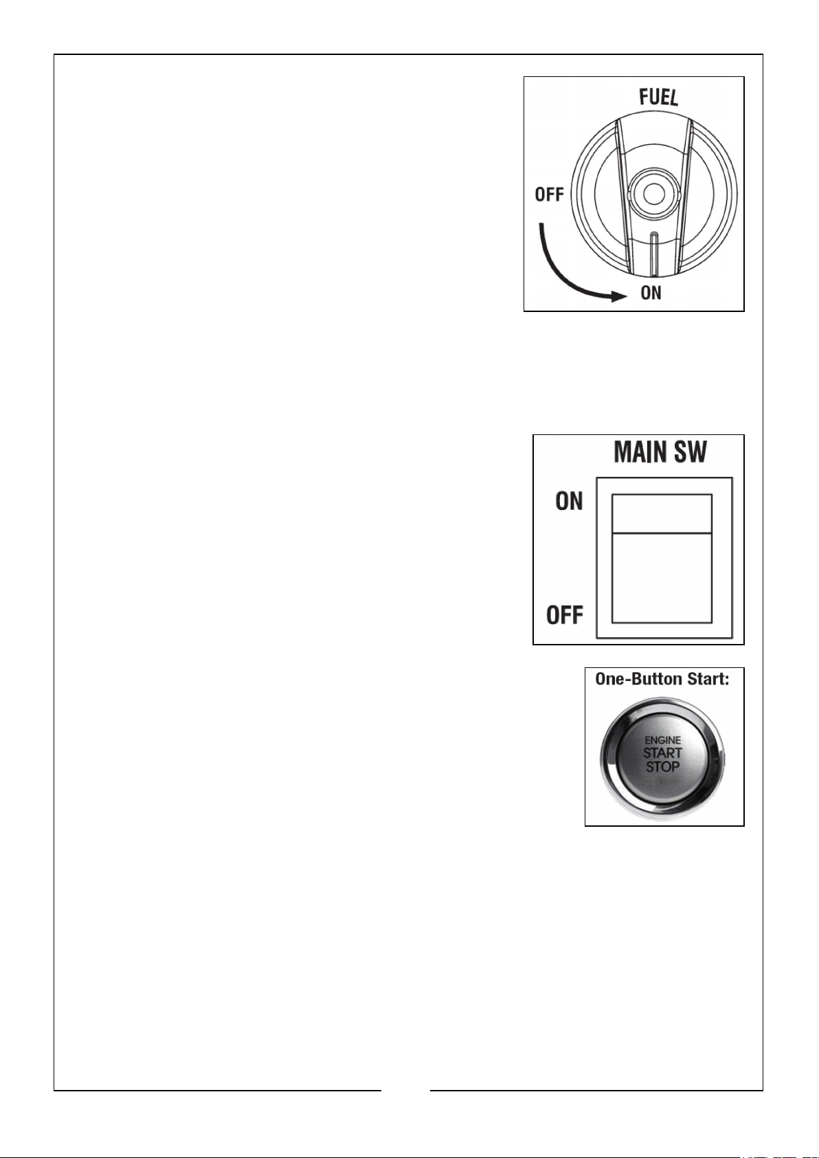
2. Turn the FUEL switch to the ‘ON’ position.
After completing steps 1 and 2, there are two ways to start the generator, either by
Electric One Button Start or Manual Start, as follows:
ELECTRIC ONE BUTTON START
1. Turn the MAIN SW switch to the ‘ON’ position.
2. Hold down the ENGINE START/STOP button for 3 seconds.
NOTE: If the engine does not start, release the button and
try again. Keeping the button compressed for too long
can damage the starter.
NOTE: If you have repeated failed attempts to start the
engine, please consult the troubleshooting guide on
page 28.
3. Allow the generator to run for several minutes before attempting to connect any
electrical devices. This allows the generator to stabiles its speed and temperature.
17
Parts & Service: 020 8988 7400 / E-mail: [email protected] or [email protected]
Page 18
MANUAL START
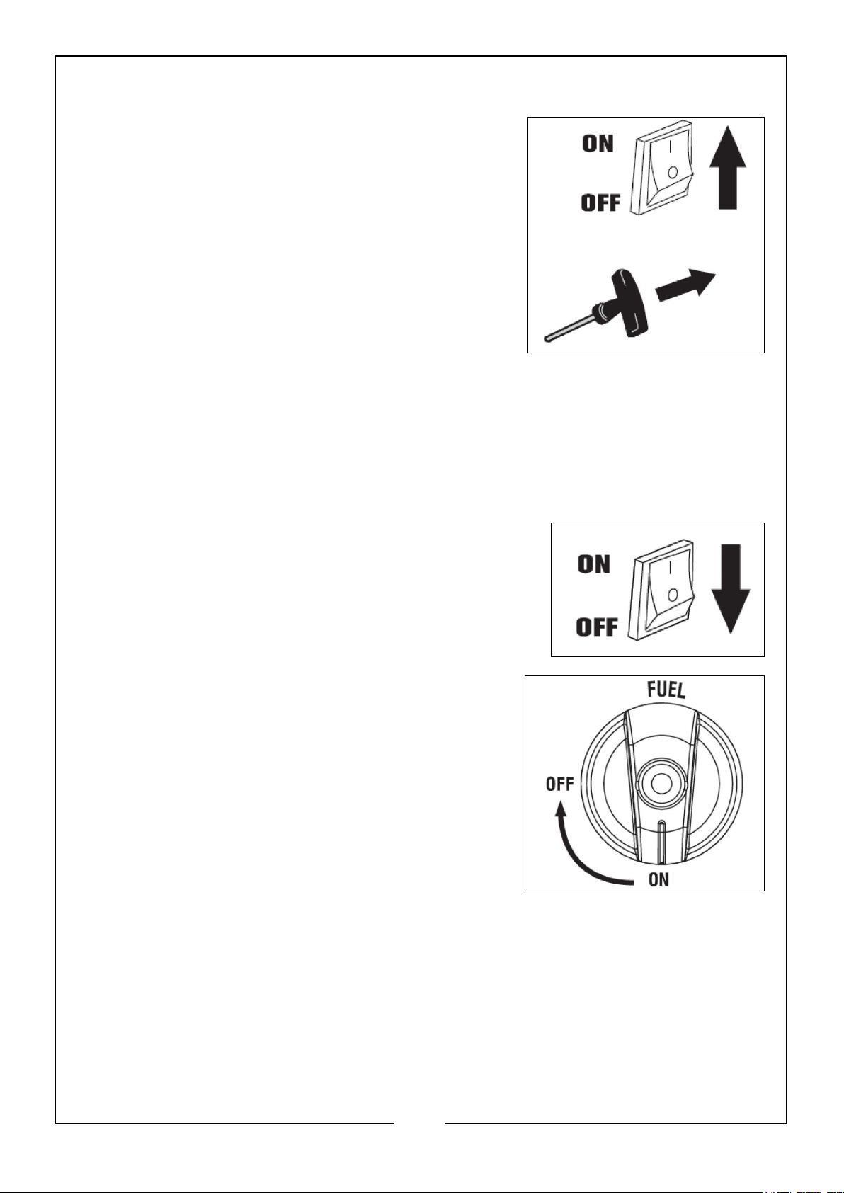
1. Turn the ENGINE switch to the ‘ON’ position.
2. Place one hand on the generator to hold it in
place, and pull on the recoil starter handle slowly
until a slight resistance is felt. Then pull quickly
start the engine. Return cord gently into the
machine. NEVER allow the cord to snap back.
3. Allow the generator to run for several minutes
before attempting to connect any electrical
devices. This allows the generator to stabiles its
speed and temperature.
SHUTTING OFF THE GENERATOR
1. Turn off all electrical devices prior to unplugging them from the generator.
Unplugging running devices can cause damage to the generator.
2. Allow the generator to run at no load for a few minutes to stabilise the internal
temperature.
3. Turn the ENGINE switch to the ‘OFF’ position.
4. Turn the FUEL switch to the ‘OFF’ position.
WARNING: ALLOW THE GENERATOR TO COOL
DOWN BEFORE TOUCHING AREAS THAT BECOME HOT DURING USE.
CAUTION: ALLOWING PETROL TO SIT IN THE FUEL TANK FOR LONG
PERIODS OF TIME CAN MAKE IT DIFFICULT TO START THE GENERATOR IN
THE FUTURE. NEVER STORE THE GENERATOR FOR EXTENDED PERIODS OF
TIME (OVER 2 MONTHS) WITH FUEL IN THE TANK. REFER TO ‘STORING THE
GENERATOR’ ON PAGE 25
18
Parts & Service: 020 8988 7400 / E-mail: [email protected] or [email protected]
Page 19
MAINTENANCE
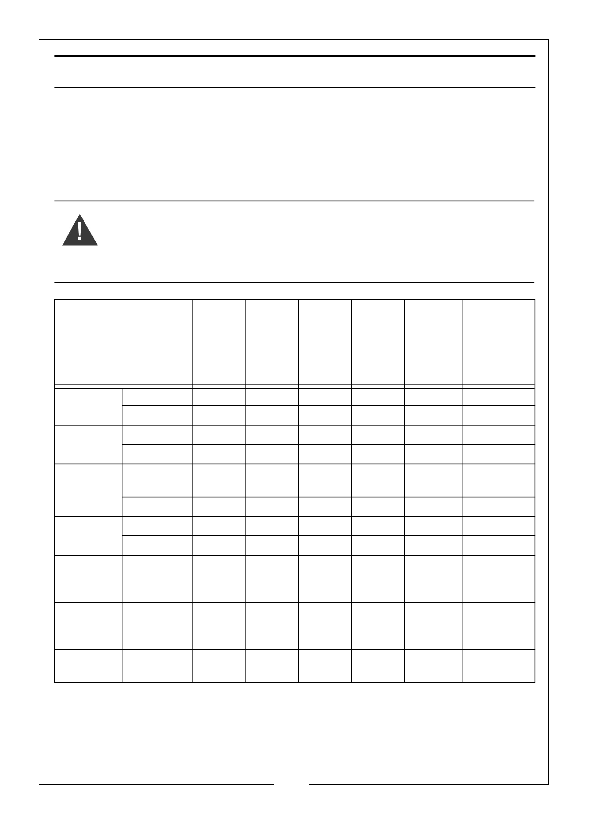
Proper routine maintenance of the generator will help prolong the life of the machine.
Please perform maintenance checks and operations according to the Maintenance
Schedule below.
If there are any questions about the maintenance procedures listed in this manual,
please contact the CLARKE service centre.
WARNING: NEVER PERFORM MAINTENANCE OPERATIONS WHILE
THE GENERATOR IS RUNNING. BEFORE MAINTENANCE OR
SERVICING THE GENERATOR, TURN OFF THE GENERATOR,
DISCONNECT ALL DEVICES AND ALLOW THE GENERATOR TO COOL
DOWN
RECOMMENDED
MAINTENANCE
SCHEDULE
Engine Oil
(Page 24)
Air Filter
(Page 21)
Spark
Plug
(Page 22)
Fuel Tank
(Page 23)
Carbureto
r
(Page 23)
EVERY
8HRS
OR
DAILY
Check Level X
Replace X* X X
Check X*
Clean X*
Check/
Clean/Regap
Change X X
Check Level X
Drain X X
Drain X X
EVERY
25HRS
EVERY
3MTH
OR
50HRS
EVERY
6MTH
OR
100HR
S
X
BEFORE
STORAGE
AS
NECESSARY
Spark
Arrestor
(Page 23)
Battery
(Page 14)
Check/Clean X
Disconnect X
* = Clean/Change more often under dusty conditions or operating under heavy load.
19
Parts & Service: 020 8988 7400 / E-mail: [email protected] or [email protected]
Page 20
IMPORTANT GENERATOR MAINTENANCE TIPS:
• Drain the carburetor after each use and before storage to prevent it from
clogging.
• DO NOT store the generator with fuel inside the tank for more than 2 months fuel will go bad.
• Run the generator for at least 20 minutes every month to charge the battery and
maximise the generators lifespan.
NOTE: Failure to properly maintain the generator will void the warranty.
AIR FILTER MAINTENANCE
Check every 50 hours of operation (refer to recommended maintenance schedule).
Routine maintenance of the air filter helps maintain proper airflow to the carburetor.
Occasionally check that the air cleaner is free of excessive dirt.
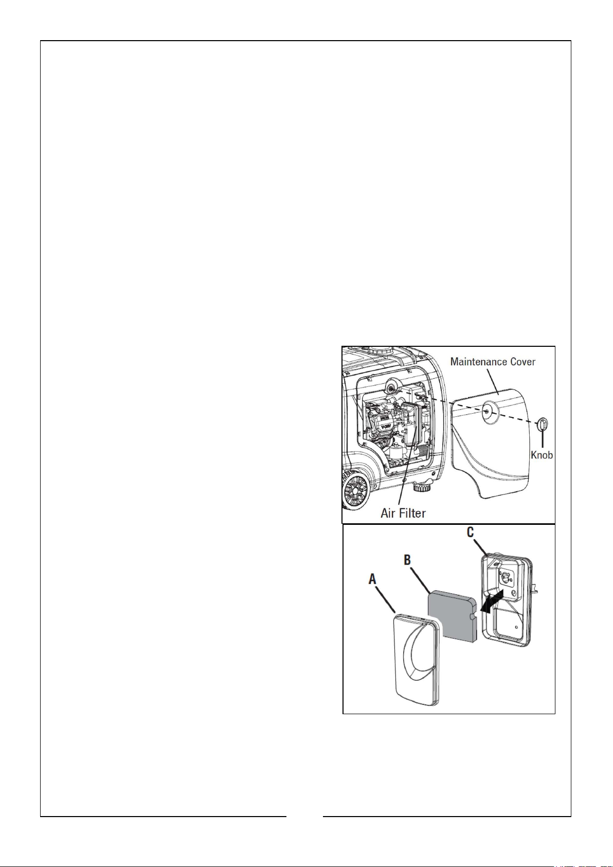
TO INSPECT AND CLEAN THE AIR FILTER:
1. Unscrew the maintenance cover knob, and
remove the cover from the side panel.
2. Take the cover off of the air cleaner (A).
Remove the foam air filter element (B)
from the casing. Wipe excessive oil and
any dirt from inside the air filter casing (C).
3. Check and clean the foam air filter
element. Good elements can be washed in
soapy water. Dry the element with a clean
cloth (DO NOT twist it). Add a few drops
of engine oil to the air filter element and
spread it evenly.
4. If the air filter element has been
damaged, replace it with a new one.
5. Reinstall the air filter element, air filter cover and maintenance cover.
20
Parts & Service: 020 8988 7400 / E-mail: [email protected] or [email protected]
Page 21
NOTE: Running the engine with a dirty, damaged or missing air filter element
can result in danger to the operator and cause the engine to wear out
prematurely.
SPARK PLUG MAINTENANCE
The spark plug must be properly gapped and free of deposits in order to ensure
proper engine operation. If the engine is hot, allow it to cool before servicing the
spark plug (refer to recommended maintenance schedule).
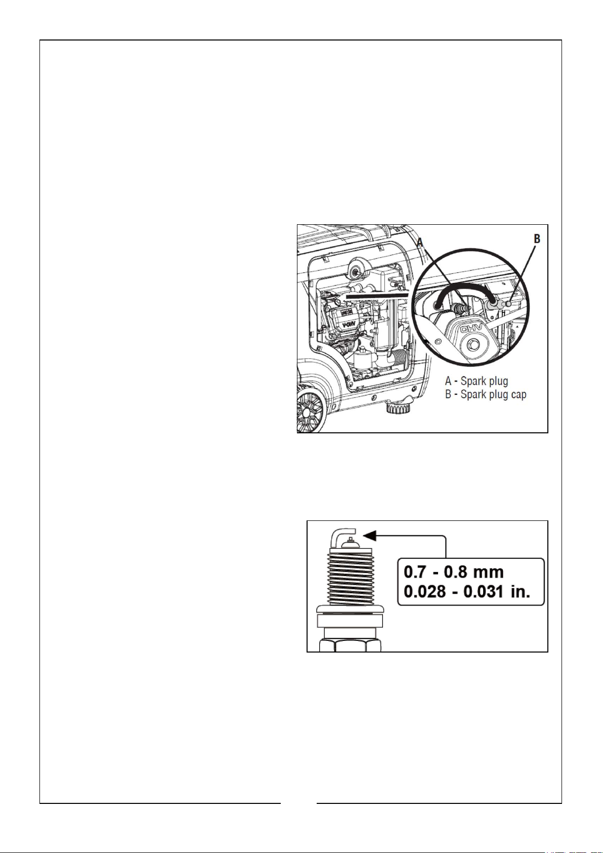
TO INSPECT OR REPLACE THE SPARK PLUG:
1. Unscrew the maintenance cover
knob and remove the cover from
the side panel.
2. Remove the spark plug cap.
3. Use the included spark plug
spanner to unscrew and then
carefully remove the spark plug
from the engine.
NOTE: There is limited space for the
spanner to turn, use the arm
to gain leverage to loosen the
plug.
4. Visually inspect the spark plug. If it is cracked or chipped, or if the electrodes are
worn or burned, discard it and replace with a new spark plug.
5. If re-using the spark plug, use a wire brush to clean any dirt from around the
spark plug base, then re-gap the spark plug.
6. Measure the plug gap with a spark
plug gap gauge. The gap should be
0.7 - 0.8mm (0.028 - 0.031in).
Carefully adjust the gap if necessary.
7. Screw the spark plug back into the
spark plug hole using the spark plug
spanner. DO NOT over-tighten the
spark plug. Recommended tightening
a spark plug is 1/2 to 4/3 of a turn
(15ft/lb torque/20.33Nm) after the spark plug gasket contacts the spark plug
hole.
8. Reinstall the spark plug cap and maintenance cover.
SPARK ARRESTOR MAINTENANCE
Inspect and clean the spark arrestor every 100 hours of operation (refer to
recommended maintenance schedule). The spark arrestor is located outside the
21
Parts & Service: 020 8988 7400 / E-mail: [email protected] or [email protected]
Page 22
muffler, which gets very hot during operation. Allow the engine and the muffler to
cool completely before servicing the spark arrestor.
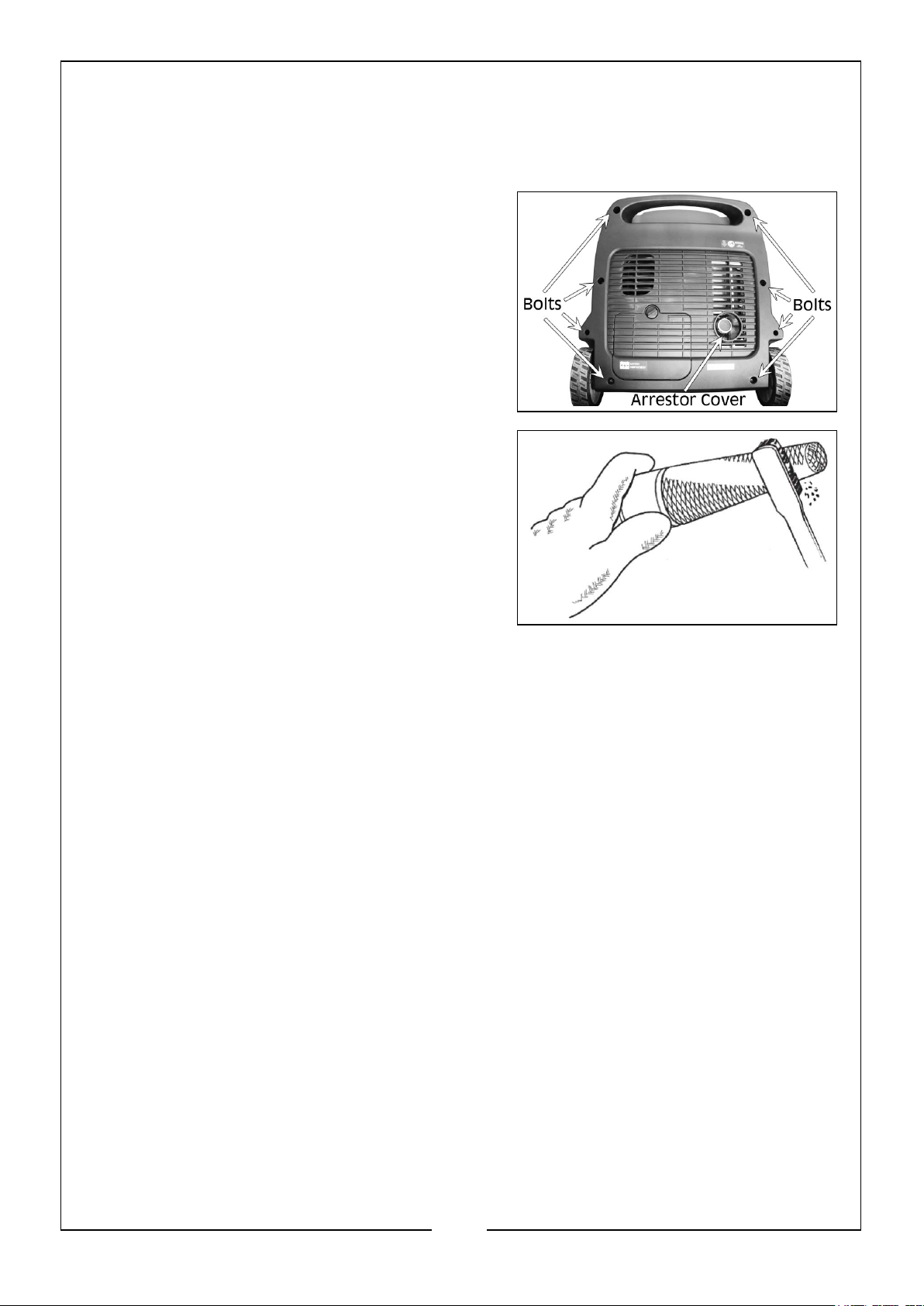
TO INSPECT AND CLEAN THE SPARK ARRESTOR:
1. Loosen the 8 bolts from the rear cover and
remove, then loosen the jubilee clip
holding the arrestor cover in place and
remove the arrestor from its housing.
2. Use a brush to remove carbon deposits
from the spark arrestor screen. Be careful
to avoid damaging the screen. The spark
arrestor must be free of breaks and tears.
Replace the spark arrestor if it is damaged.
3. Install the spark arrestor in the reverse
order of removal.
DRAINING THE FUEL TANK/CAR-
BURETTOR
To help prevent gum deposits in the fuel system, drain the fuel from the tank and
carburetor before storing.
TO DRAIN THE FUEL TANK & CARBURETOR:
1. With the help of another person, place the generator on an elevated platform such
as a table or workbench.
2. Unscrew the maintenance cover knob, and remove the cover from the side panel.
TO DRAIN THE FUEL TANK
NOTE: Make sure that the fuel switch is turned to ‘ON’, as this will let the fuel
drain through the carburetor.
22
Parts & Service: 020 8988 7400 / E-mail: [email protected] or [email protected]
Page 23
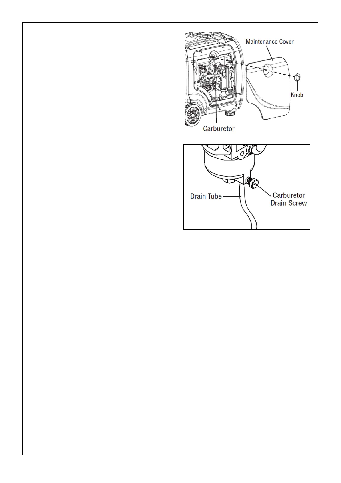
TO DRAIN THE CARBURETOR
NOTE: Make sure that the fuel switch is
turned to ‘OFF’, at this position, the
fuel valve is turned OFF so that
only the fuel left inside the
carburetor will be drained out.
3. The carburetor can be accessed
between the engine and air filter. Locate
the transparent tube from the
carburetor that extends down through
the base plate of the generator.
4. Prepare an approved petrol storage
container and direct the end of the drain
tube into the container.
5. Open up the carburetor drain screw with
a flat head screwdriver (not included)
and drain out any petrol that has built up inside the carburetor through the drain
tube into the petrol storage container.
6. Once the fuel has been drained, tighten the drain screw with the screwdriver.
NOTE: Make sure to drain the carburetor before storing the generator for long
periods of time.
7. Reinstall the maintenance cover.
DRAINING/CHANGING THE OIL
Change the oil more often if operating under heavy load or high ambient
temperature. It is also necessary to drain the oil from the crankcase if it has become
contaminated with water or dirt. Changing the oil when the engine is warm allows for
complete drainage. Change the oil according to the recommended maintenance
schedule on page 20.
TO CHANGE THE ENGINE OIL:
1. With the help of another person, place the generator on an elevated platform such
as a table or workbench.
23
Parts & Service: 020 8988 7400 / E-mail: [email protected] or [email protected]
Page 24
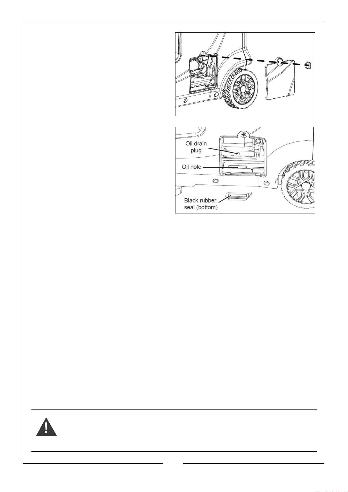
2. Unscrew the oil access cover knob,
and remove the cover from the side
panel.
3. Place a suitable container
underneath the generator to catch
the used oil.
4. Reach under the generator and
remove the black rubber seal located
below the oil drain plug.
5. Remove the oil fill cap/dipstick.
6. Use a spanner to remove the oil
drain plug and allow the oil to drain
completely.
7. Reinstall the oil drain plug after the
oil has drained.
8. Reinstall the black rubber seal.
NOTE: NEVER dispose of used engine oil in general rubbish or down a drain.
See local authority recycling for more information.
9. With the generator in a level position, refill the the engine with new oil. See
section Add/Check Oil on page 12.
10. Reinstall the oil dipstick and tighten it securely. Wipe clean any oil spillage and
reinstall the oil access cover.
TRANSPORTING THE GENERATOR
To prevent fuel spillage when transporting, be sure to perform the following:
1. Tighten the fuel cap and turn the vacuum relief valve to ‘OFF’
2. Set the engine switch to ‘OFF’.
3. Drain the fuel tank if possible, see section Draining the Fuel Tank/Carburetor on
page 23.
4. Keep the generator upright. NEVER place the generator on its side or upside
down - doing so will make it difficult to start next time.
WARNING: AVOID DIRECT SUNLIGHT INSIDE A VEHICLE. IF THE
GENERATOR IS LEFT IN AN ENCLOSED VEHICLE FOR MANY HOURS,
THE HIGH TEMPERATURE COULD CAUSE THE FUEL TO VAPORISE
AND RESULT IN A POSSIBLE EXPLOSION.
24
Parts & Service: 020 8988 7400 / E-mail: [email protected] or [email protected]
Page 25

STORING THE GENERATOR
Shut off the generator and allow the unit to cool to room temperature before storing
it. NEVER place any type of storage cover on the generator while it is still hot. DO
NOT obstruct any ventilation openings.
Follow the procedures below for properly storing your generator. We highly
recommend running your generator once a month for 20 to 30 minutes. Plug in a
small load to ensure there is proper power output.
FOR SHORT PERIODS (30 TO 60 DAYS)
NOTE: DO NOT store fuel for more than 2 months
• Drain the carburetor (see section Draining the Fuel Tank/Carburetor on pages 23 -
24).
• Disconnect the negative lead from the battery (see section Connecting the Battery
on page 14).
• Add fuel stabiliser. Follow the suggested portions and instructions for your
preferred stabiliser. Run the engine for 15 to 20 minutes, allowing the fuel
stabiliser to mix with the petrol and circulate through the carburetor, and then top
off with fuel. Filling the fuel tank full reduces the amount of air in the tank and
helps fight deterioration of the fuel.
FOR EXTENDED PERIODS (OVER 60 DAYS)
• Disconnect the negative lead from the battery (see section Connecting the Battery
on page 14).
• Drain the fuel tank and carburetor (see section Draining the Fuel Tank/Carburetor
on page 23). NEVER store the generator with fuel in the tank for more than two
months.
• Change the engine oil (see section Draining and Changing the Oil on page 24).
WARNING: STORE THE GENERATOR UPRIGHT IN A COOL AND DRY
LOCATION, AWAY FROM SOURCES OF HEAT, OPEN FLAMES, SPARKS
OR PILOT LIGHTS.
PRODUCT DISPOSAL
DO NOT dispose of used generator or parts with your household waste. This product
contains electrical or electronic components that should be recycled under the WEEE
regulations. Please take this product to your local recycling facility for responsible
disposal to minimise its environmental impact.
DO NOT dispose of used oil or fuel in general waste or down a drain. Please see local
authority recycling for more information.
25
Parts & Service: 020 8988 7400 / E-mail: [email protected] or [email protected]
Page 26
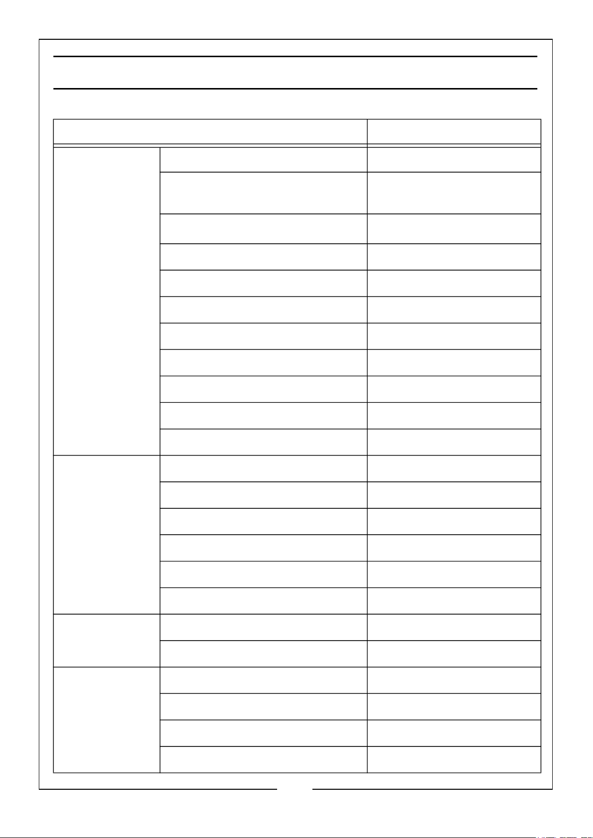
SPECIFICATIONS
CLARKE part no 8877130 IG4000
Engine Engine Model SV230
Fuel Type Unleaded Petrol
(87 Octane Rate Min.)
Displacement (cm3)
Start system Electric & Hand recoil
Fuel tank capacity (L) 10 L
Fuel consumption 1.6 L/Hr
Maximum run time @75% Load 6 hours 15 mins
Engine oil type SAE10W30
Engine oil capacity (L) 0.6L
Battery 7Ah Sealed Lead Acid
High Temperature Shut Down 80°C
Generator Rated Frequency (Hz) 50
AC Output Voltage (V) 230V x 2
223
DC Output Voltage (V) 5V x 1 & 12V x 1
Rated Running Power (W) 3500
Max. Starting Power (W) 3800
IP Rating IP23M
Dimensions Depth x Width x Height (mm) 550 x 650 x 580
Unpacked Weight (kg) 52.8
Environmental Sound pressure level 58 dB
Sound power level 92 dB
Guaranteed sound power level 95 dB
Uncertainty factor 2.9 dB
26
Parts & Service: 020 8988 7400 / E-mail: [email protected] or [email protected]
Page 27
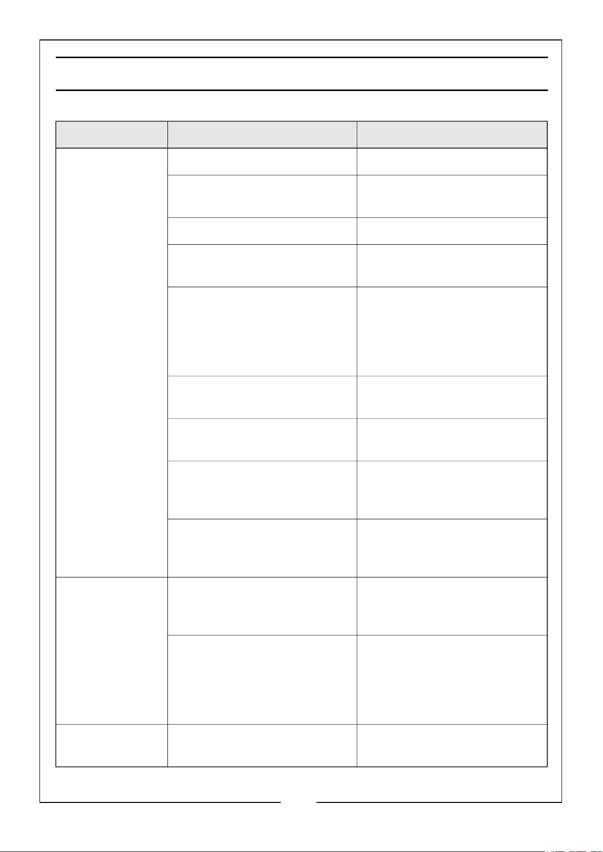
TROUBLESHOOTING
PROBLEM POSSIBLE CAUSE SOLUTION
The generator
fails to start
Battery not charged Charge battery
Engine switch is in the OFF
position
No Fuel Fill fuel tank (see page 13)
Stale petrol or water in petrol Drain entire system and refill
Engine oil level is low Engine is equipped with Low Oil
Fuel switch is in the OFF
position
Spark plug faulty, fouled, or
improperly gapped
Turn engine switch to the ON
position
with fresh fuel (see page 23)
Shutoff. If engine oil level is low,
it must be filled before unit will
start. Check engine oil level and
fill if necessary (see page 12)
Turn fuel switch to the ON position
Replace spark plug (see page
22)
Engine lacks
power
The generator is
difficult to start
Engine stored without
treating or draining petrol, or
refueled with bad petrol
Dirty fuel filter Replace fuel filter or contact the
Dirty air filter Check air filter element. Clean
Engine stored without
treating or draining petrol, or
refueled with bad petrol
The air filter is dirty. Clean the air filter (Page 21).
Drain fuel. Refuel with fresh petrol (see page 23)
CLARK service
department
or replace as needed (see page
21)
Drain fuel. refuel with fresh petrol (see page 23). If
problem continues, contact the
CLARK service
department
27
Parts & Service: 020 8988 7400 / E-mail: [email protected] or [email protected]
Page 28
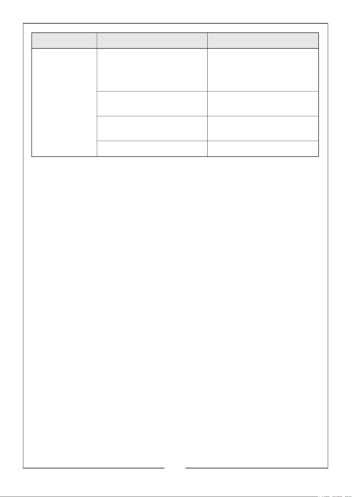
PROBLEM POSSIBLE CAUSE SOLUTION
AC receptacle does
not work
OUTPUT indicator is OFF, and
OVERLOAD indicator is ON
Check AC load (see page 10).
Stop and restart the engine.
Check the cooling air inlet. Stop
and restart the engine.
AC Circuit protector has tripped Check AC load and reset AC cir-
cuit protectors (see page 9)
GFCI system has activated (if
Reset the GFCI
used)
Item plugged in is defective Try a different device.
If this does not solve your problem contact the CLARKE service department.
28
Parts & Service: 020 8988 7400 / E-mail: [email protected] or [email protected]
Page 29

ENVIRONMENTAL RECYCLING POLICY
Through purchase of this product, the customer is taking on the obligation
to deal with the WEEE in accordance with the WEEE regulations in relation
to the treatment, recycling & recovery and environmentally sound disposal
of the WEEE.
In effect, this means that this product must not be disposed of with general
household waste. It must be disposed of according to the laws governing Waste
Electrical and Electronic Equipment (WEEE) at a recognised disposal facility.
If disposing of this product or any damaged components, do not dispose of with
general waste. This product contains valuable raw materials. Metal products should
be taken to your local civic amenity site for recycling of metal products.
29
Parts & Service: 020 8988 7400 / E-mail: [email protected] or [email protected]
Page 30
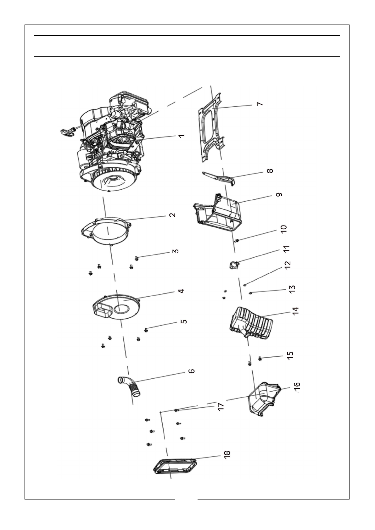
PARTS LISTS AND DIAGRAMS
MACHINE CORE COMPONENTS
30
Parts & Service: 020 8988 7400 / E-mail: [email protected] or [email protected]
Page 31
ITEM DESCRIPTION QTY
1 Engine SV230, Inverter Generator Engine 1
2 Alternator Hood 1
3 Hexagon Flange Bolt 4
4 Alternator Back Cover 1
5 Hexagon Flange Bolt 4
6 Air Inlet Pipe 1
7 Engine Support Plate 1
8 Support Plate 1
9 Muffler Exhaust Hood 1
10 Hexagon Flange Bolt 1
11 Muffler Gasket 2
12 Spring Washer 2
13 Hexagon Flange Bolt 2
14 Muffle/Exhaust 1
15 Hexagon Flange Bolt 2
16 Muffler/Exhaust Front Cover 1
17 Hexagon Flange Bolt 6
18 Outlet Rubber Sleeve 1
31
Parts & Service: 020 8988 7400 / E-mail: [email protected] or [email protected]
Page 32
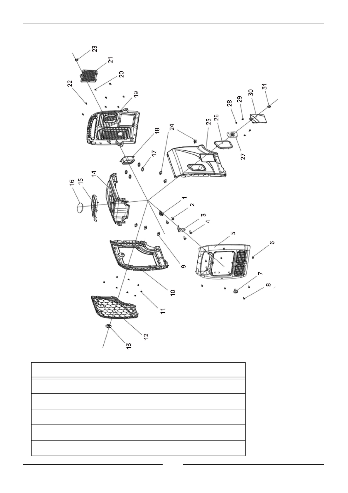
OVERLAY COMPONENTS
ITEM DESCRIPTION QTY
1 Fuel Key 1
2 Hexagon Flange Bolt 2
3 Locating Plate 1
4 Hexagon Flange Bolt 2
5 Control Panel Assembly 1
32
Parts & Service: 020 8988 7400 / E-mail: [email protected] or [email protected]
Page 33
ITEM DESCRIPTION QTY
6 Hexagon Flange Bolt 6
7 Fuel Switch 1
8 Cross Recessed Pan Head Screw 1
9 Clamp Nut 3
10 Left Shell Assembly 1
11 Spring Clip 8
12 Repair Cover Assembly 1
13 Switch 1
14 Upper Cover 1
15 Fuel Tank Rubber Sleeve 1
16 Fuel Cap 1
17 Wire Retaining Ring for Hole 4
18 Motor Rubber Sleeve 1
19 Exhaust Cover Assembly 1
20 Cross Recessed Pan Head Screw 2
21 Battery Maintenance Cover 1
22 Hexagon Flange Bolt 6
23 Thumb Screw 1
24 Clamp Nut 3
25 Right Shell Assembly 1
26 Recoil Starter Protective Ring 1
27 Handle Bezel 1
28 Hexagon Flange Bolt 2
29 Hexagon Flange Bolt 2
30 Oil Window Cover 1
31 Thumb Screw 1
33
Parts & Service: 020 8988 7400 / E-mail: [email protected] or [email protected]
Page 34
Page 35
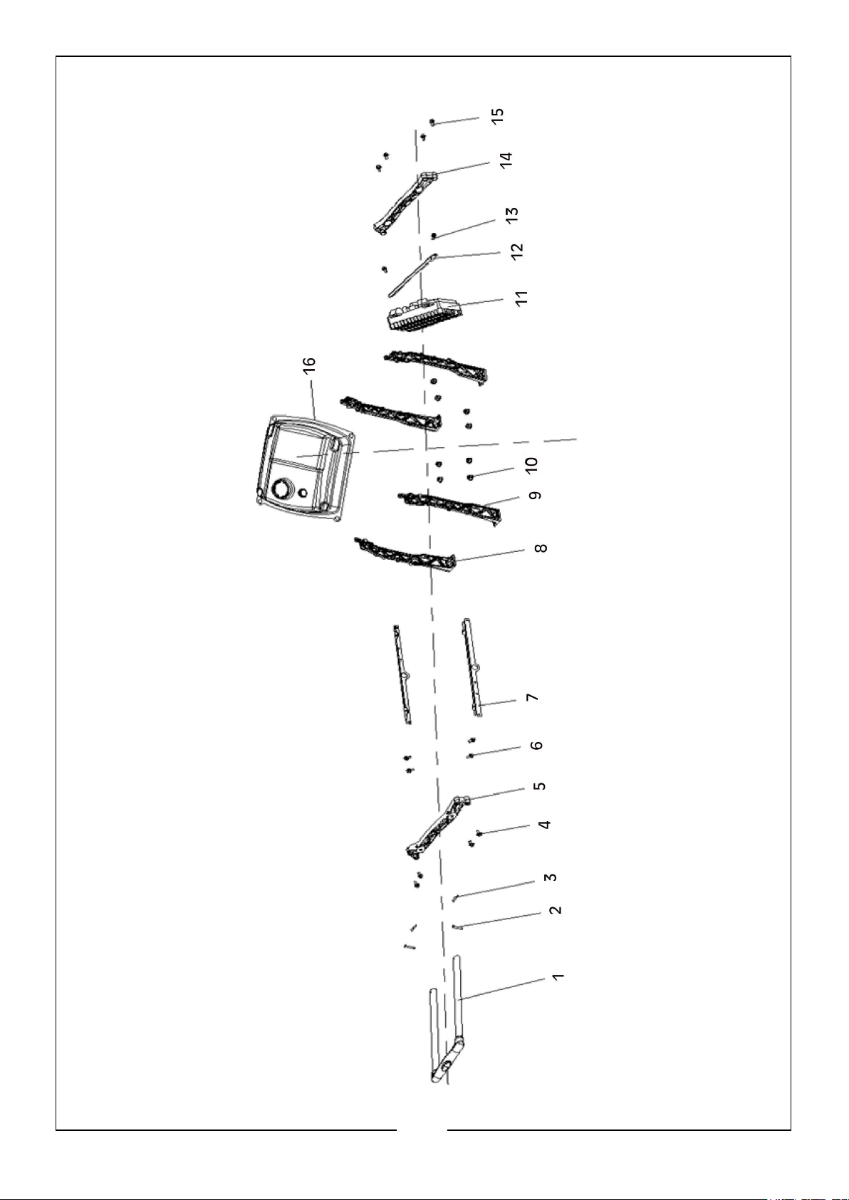
ITEM DESCRIPTION QTY
1 Telescopic Handle Assembly 1
2 Positioning Latch 2
3 Locating Pin Locking Clip 2
4 Hexagon Flange Bolt 4
5 Handle Mounting Plate 1
6 Hexagon Flange Bolt 4
7 Fuel Tank Beam 2
8 Support Frame 2
9 Support Frame 2
10 Hexagon Flange Bolt 8
11 Inverter Parts 1
12 Inverter Fixing Bracket 1
13 Hexagon Flange Bolt 2
14 Handle Mounting Plate 1
15 Hexagon Flange Bolt 4
16 Fuel Tank Assembly 1
35
Parts & Service: 020 8988 7400 / E-mail: [email protected] or [email protected]
Page 36
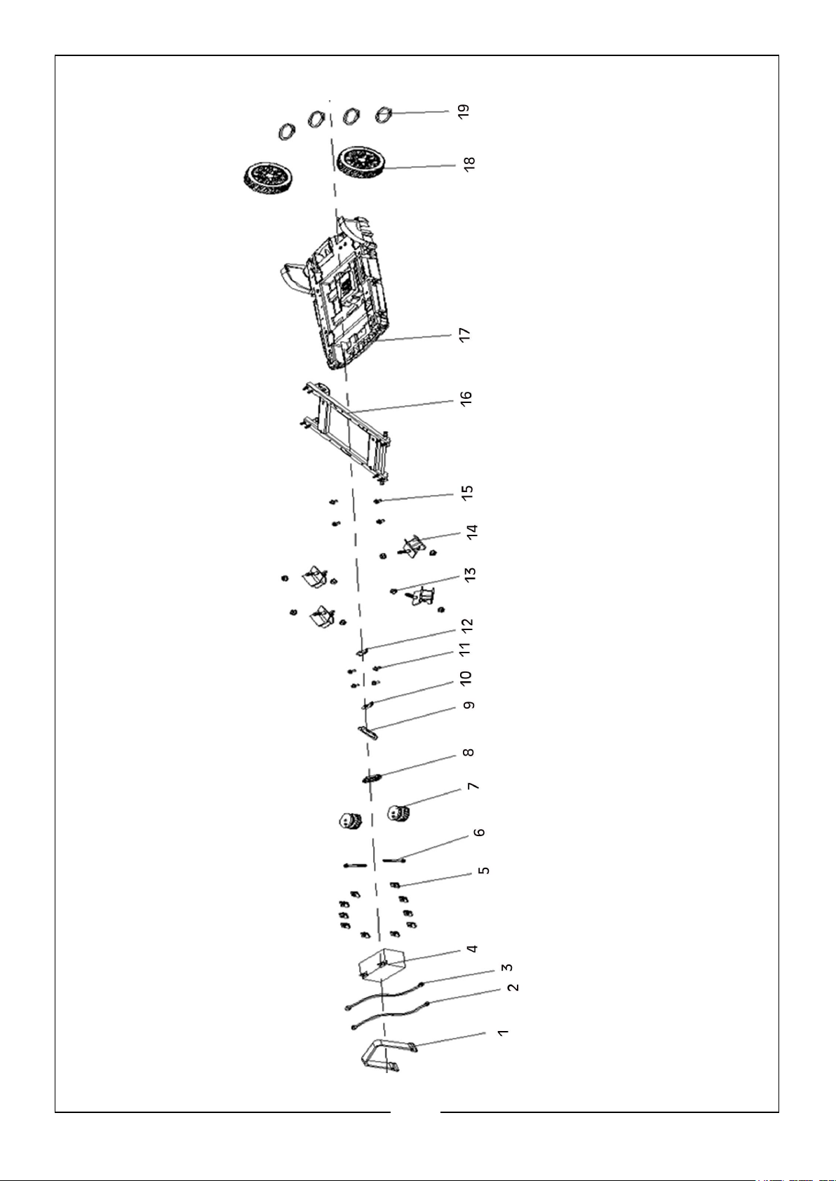
BASE PLATE ASSEMBLY COMPONENTS
36
Parts & Service: 020 8988 7400 / E-mail: [email protected] or [email protected]
Page 37
ITEM DESCRIPTION QTY
1 Battery Band 1
2 Harness Part 1
3 Harness Part 1
4 Battery 1
5 Clamp Nut 10
6 Hexagon Flange Bolt 2
7 Shock Absorber 2
8 Sealing Rubber Sleeve 1
9 Engine Oil Port Rubber Sleeve 1
10 Fixed Plate 1
11 Hexagon Flange Bolt 4
12 Fixed Plate 1
13 Hexagon Flange Bolt 8
14 Shock Absorber 4
15 Hexagon Flange Bolt 4
16 Floor Bracket 1
17 Engine Plate 1
18 Wheel Assembly 2
19 Retaining Ring for Shaft 4
37
Parts & Service: 020 8988 7400 / E-mail: [email protected] or [email protected]
Page 38
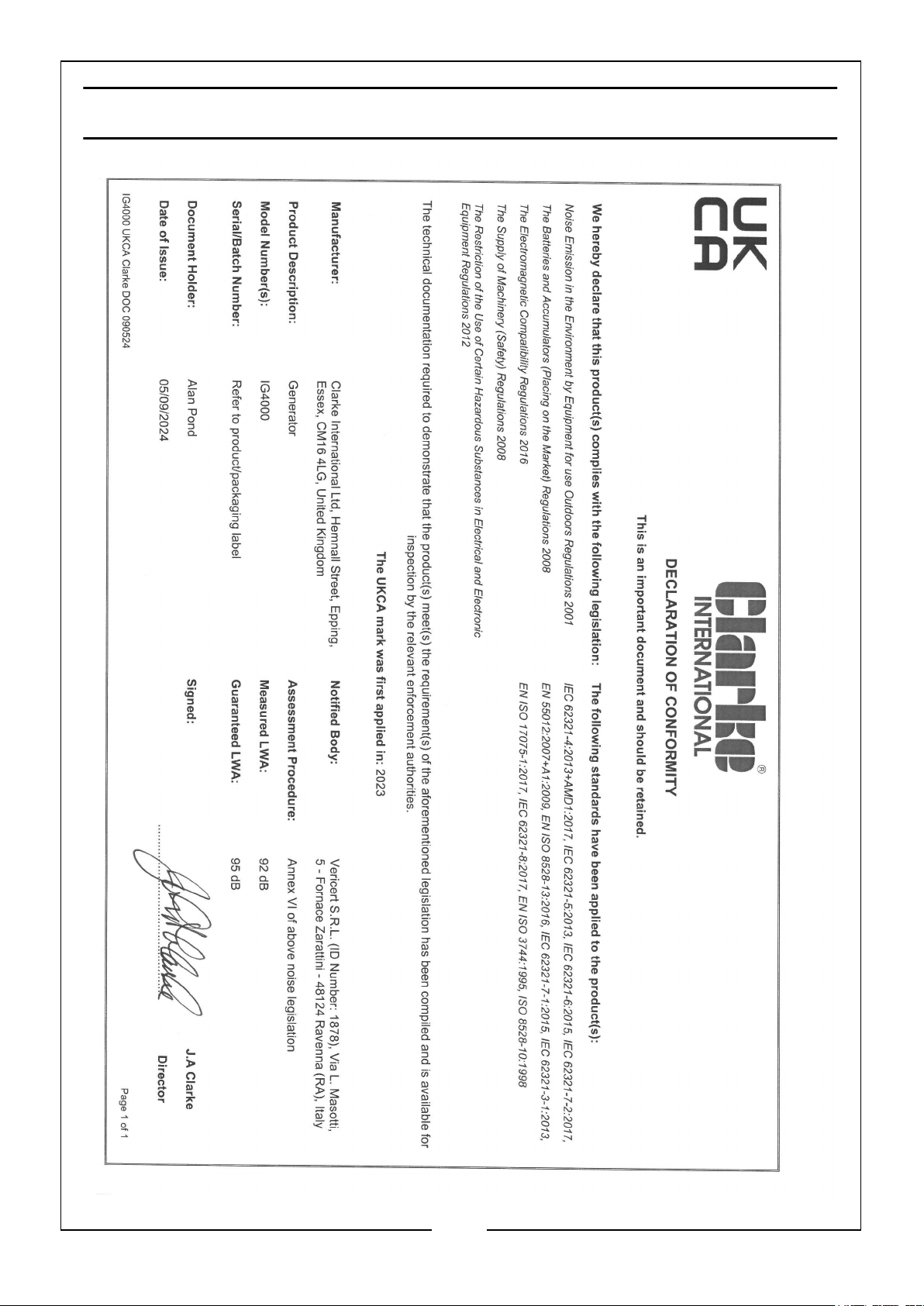
DECLARATION OF CONFORMITY - UKCA
38
Parts & Service: 020 8988 7400 / E-mail: [email protected] or [email protected]
Page 39
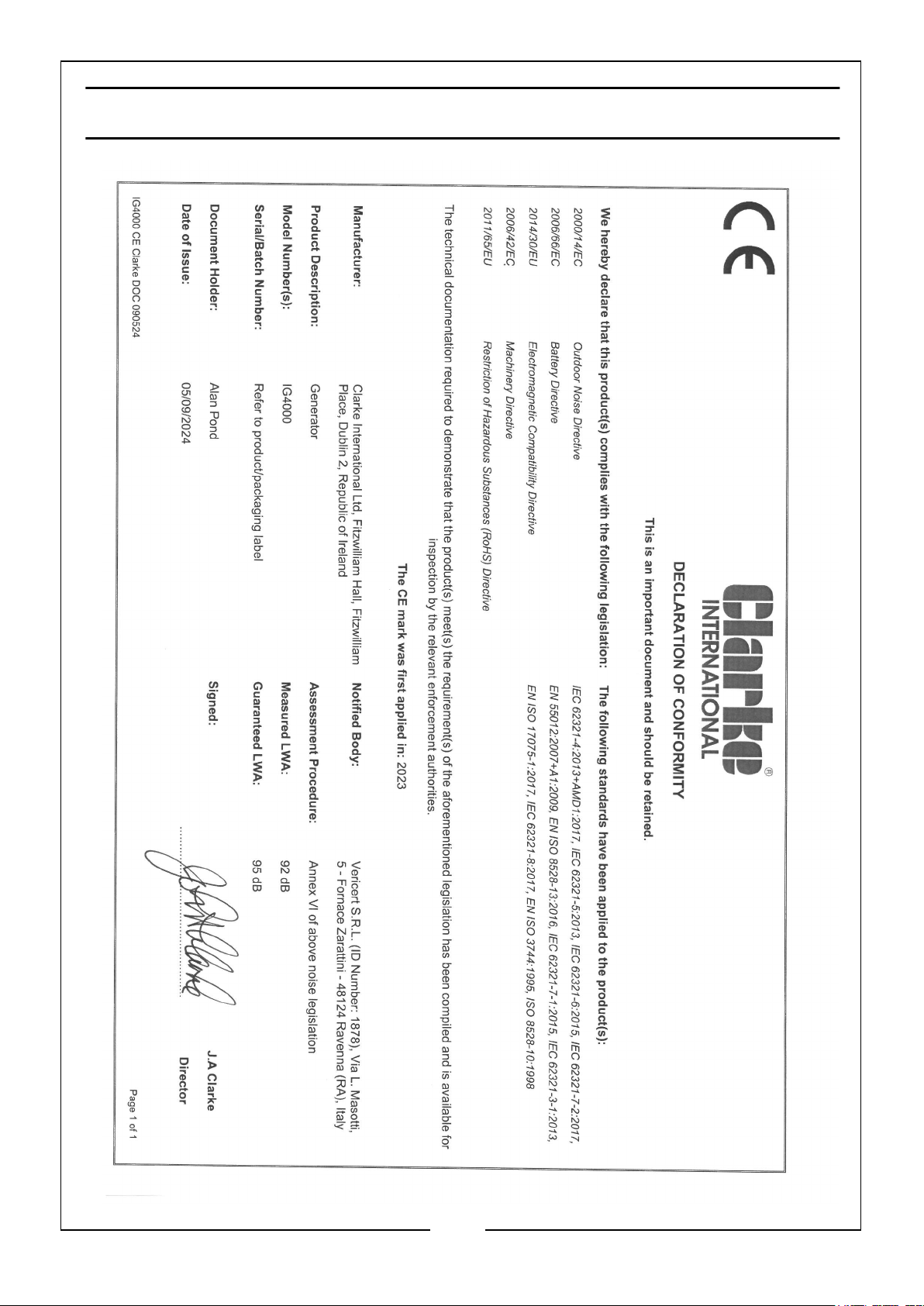
DECLARATION OF CONFORMITY - CE
39
Parts & Service: 020 8988 7400 / E-mail: [email protected] or [email protected]
Page 40

 Loading...