

Page 1
WARNING: Do not use the generator without reading this manual
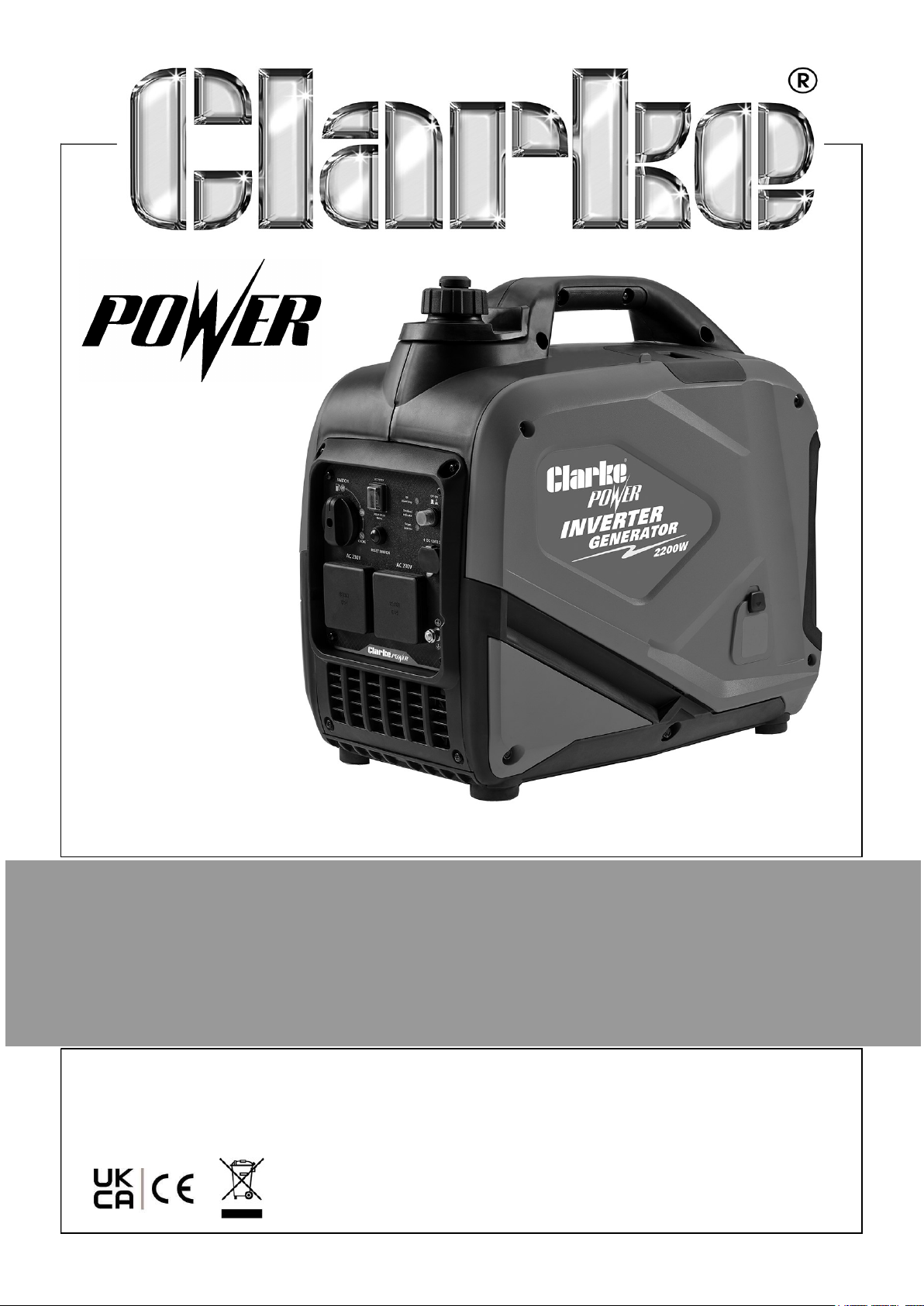
2200W INVERTER GENERATOR
MODEL NO: IG2300
PART NO: 8877121
OPERATION & MAINTENANCE
INSTRUCTIONS
ORIGINAL INSTRUCTIONS DL0425 Rev 1
Page 2
INTRODUCTION
Before you use this product, read this manual and follow the instructions carefully. In
doing so you will ensure the safety of yourself and others around you, and you can
also expect your purchase to give you a long and satisfactory service.
GUARANTEE
This product is guaranteed against faulty manufacture for a period of 12 months from
the date of purchase. Please keep your receipt which will be required as proof of
purchase.
This guarantee is invalid if the product is tampered with in any way, or not used for
the purpose for which it was intended.
Faulty goods should be returned to their place of purchase, no product can be
returned to us without prior permission. This guarantee does not effect your statutory
rights.
ENVIRONMENTAL PROTECTION
Recycle unwanted materials instead of disposing of them as waste. All
tools, accessories and packaging should be sorted and taken to a
recycling centre for disposed in a manner compatible with the
environment.
By purchasing this product, the customer is taking on the obligation to deal with its
safe disposal in accordance with the Waste Electrical and Electronic Equipment
(WEEE).
In effect, this means that this product must not be disposed of with general
household waste. It must be disposed of according to the laws governing Waste
Electrical and Electronic Equipment (WEEE) at a recognised disposal facility. If
disposing of this product or any damaged components, do not dispose of with general
waste. This product contains valuable raw materials. Metal products should be taken
to your local civic amenity site for recycling of metal products.
2
Parts & Service: 020 8988 7400 / E-mail: [email protected] or [email protected]
Page 3
SPECIFICATIONS
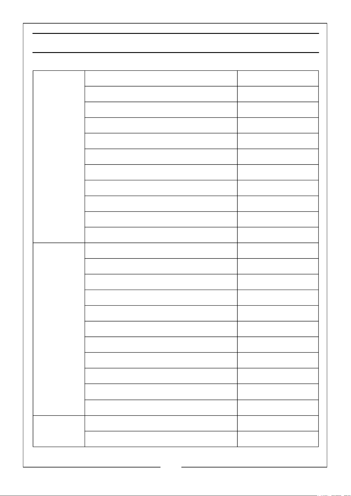
Engine Engine Model KM152F
Type Petrol
Displacement (cc) 98
RPM 5200
Ignition type T.C.I
Fuel tank capacity (L) 5.6
Fuel Consumption at 3/4 Load (L/h) 1.1
Maximum run time at 3/4 load (h) Approx. 5h
Engine oil capacity (L) 0.35
Emissions (g/kWh) CO, HC, NOx 245.89, 5.07, 3.89
Guaranteed sound power (LWA dB) 95
Generator Rated Frequency (Hz) 50
Rated AC Voltage per 13A socket x 2 (V) 230
Rated DC Voltage per socket x 1 (V) 12
Rated Output Current (A) 8.7
Maximum Rated Output Current (A) 9.6
Rated Output Power: (Continuous) (W) 1840
Maximum Rated Output Power (W) 2200
Output Type Sine Wave
Starter Type Recoil
Operating Temperatures
o
-5
C to 40oC
IP Rating IP23M
Dimensions Depth x Width x Height (mm) 465 x 307 x 500
Unpacked & Unfueled Weight (kg) 21
3
Parts & Service: 020 8988 7400 / E-mail: [email protected] or [email protected]
Page 4

GENERAL SAFETY RULES
WARNING: EXHAUST FUMES CAN BE EXTREMELY DANGEROUS IF
INHALED
WORK AREA
1. ALWAYS use in a well ventilated area.
2. ALWAYS position the exhaust outlet away from people.
3. Read these safety instructions before using the equipment.
4. Keep children away from the generator.
POSITIONING THE GENERATOR
1. Keep the generator at least 1 m (3 ft.) from buildings or other equipment, or the
engine may overheat.
2. Place the generator on a solid, flat surface.
3. Make sure the surrounding area is free from any material that could burn or be
damaged by heat.
4. NEVER move or tilt the generator whilst it is switched on.
FIRE PREVENTION
1. ALWAYS switch the engine OFF when refuelling.
2. ALWAYS refuel in a well ventilated area.
3. NEVER overfill the fuel tank, only fill to the level specified.
4. NEVER smoke whilst refuelling and avoid smoking or using a naked flame near
the generator.
5. NEVER start the engine if there is spilled fuel. Any spillage must be wiped clean
and the generator allowed to dry before attempting to start the engine.
PREVENTION OF ELECTRIC SHOCK
1. NEVER use the generator in the rain or wet conditions unless it is well protected/
under cover. Under these conditions, adequate ventilation MUST be provided.
2. NEVER operate the generator with wet hands.
3. NEVER use water or any other liquids to clean the generator.
4
Parts & Service: 020 8988 7400 / E-mail: [email protected] or [email protected]
Page 5

4. Make sure you ground (earth) the generator (See pages 9-10).
ADDITIONAL SAFETY RULES FOR GENERATORS
1. ALWAYS make sure the applied load does not exceed the generator rating.
Overloading the generator is dangerous and could cause serious damage.
2. ALWAYS turn off and
disconnect any appliance from the generator when carrying
out any maintenance.
3. ALWAYS allow the generator to reach operating speed before connecting a load.
4. NEVER allow the generator to run out of fuel when a load is connected.
5. NEVER transport the generator with fuel in the tank.
6. NEVER connect the generator to a commercial or residential power supply; e.g.
ring main.
7. NEVER allow the generator air vents to become blocked.
8. NEVER directly cover the generator while in use.
5
Parts & Service: 020 8988 7400 / E-mail: [email protected] or [email protected]
Page 6
SAFETY SYMBOLS
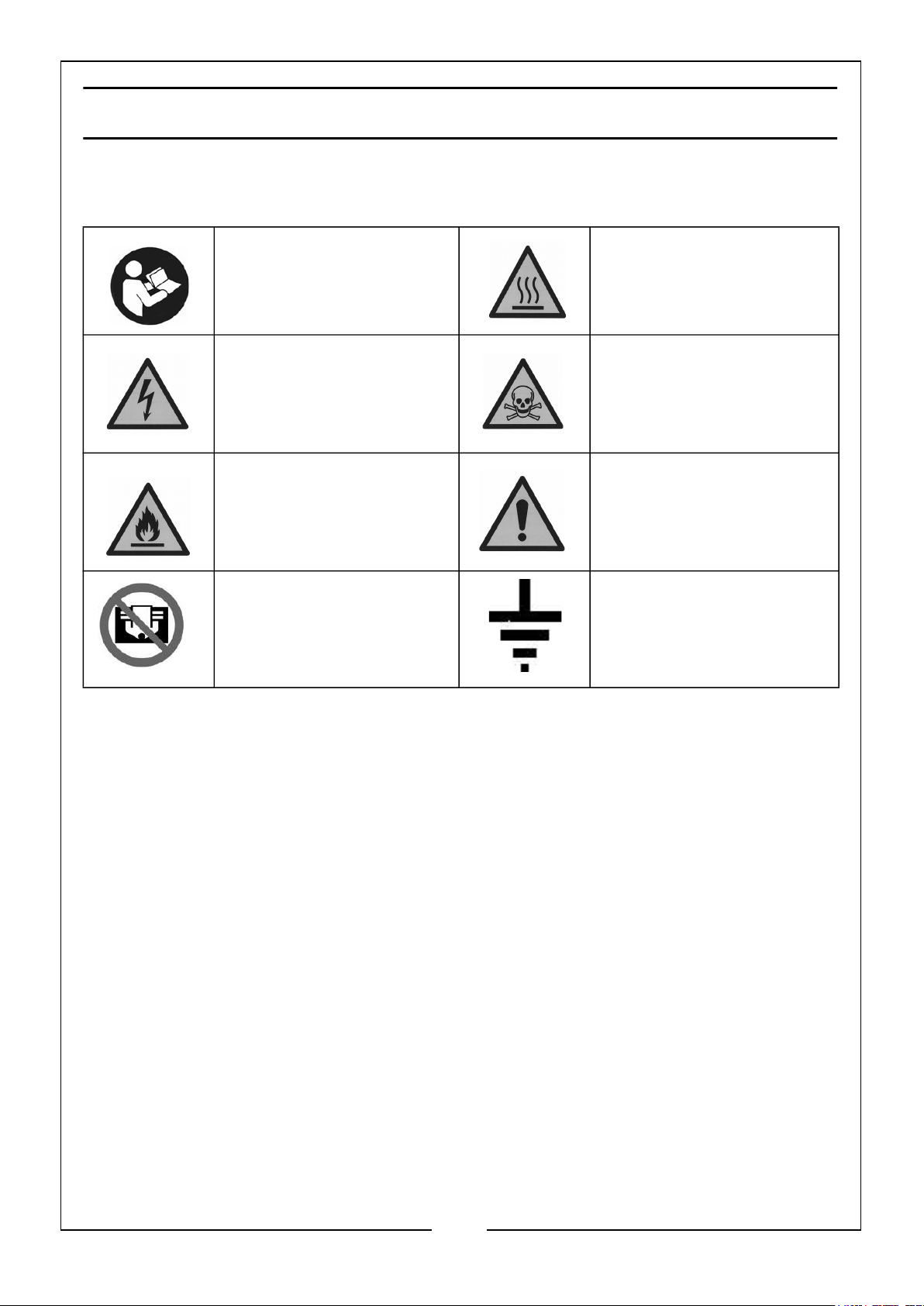
The following safety symbols are shown on the product or it’s packaging. Please read
all of the safety and operating instructions carefully before using this product.
Read instruction
manual before use.
Dangerous Voltage Risk of Electrocution.
Flammable Caution - The user
DO NOT directly cover
the generator while in
use
Hot surface - DO NOT
TOUCH
Poisonous fumes - DO
NOT use the generator
in an enclosed space.
should be aware of a
general hazard.
Earth Connection Point
6
Parts & Service: 020 8988 7400 / E-mail: [email protected] or [email protected]
Page 7
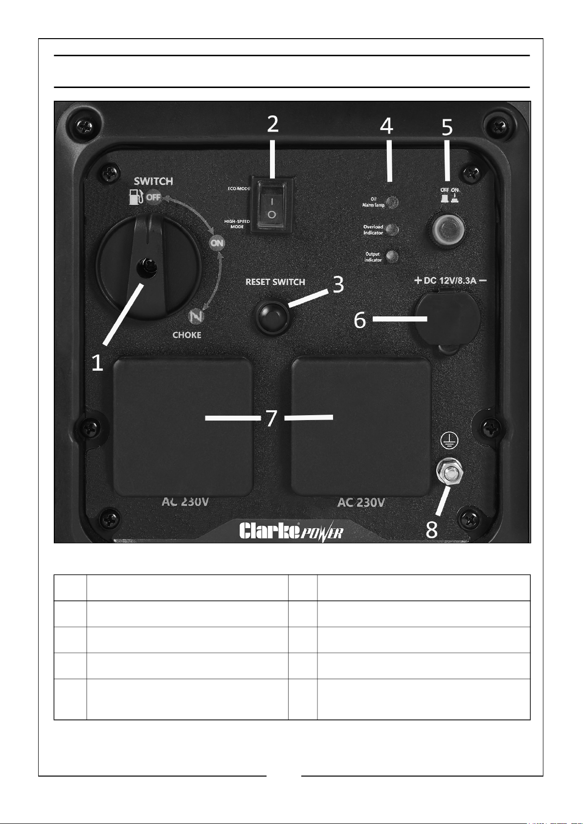
OVERVIEW - CONTROLS & OUTLETS
NO DESCRIPTION NO DESCRIPTION
1 OFF/ON/CHOKE Fuel Switch 5 DC Protector ON/OFF Switch
2 Economy Control Switch 6 2 Pin 12V/8.3A DC Outlet
3 Reset Button 7 2 x 3 Pin 13A 230V AC Outlets
4 Oil Alarm, Overload & Output
Indicator Lights
Parts & Service: 020 8988 7400 / E-mail: [email protected] or [email protected]
8 Earth Connection Point
7
Page 8
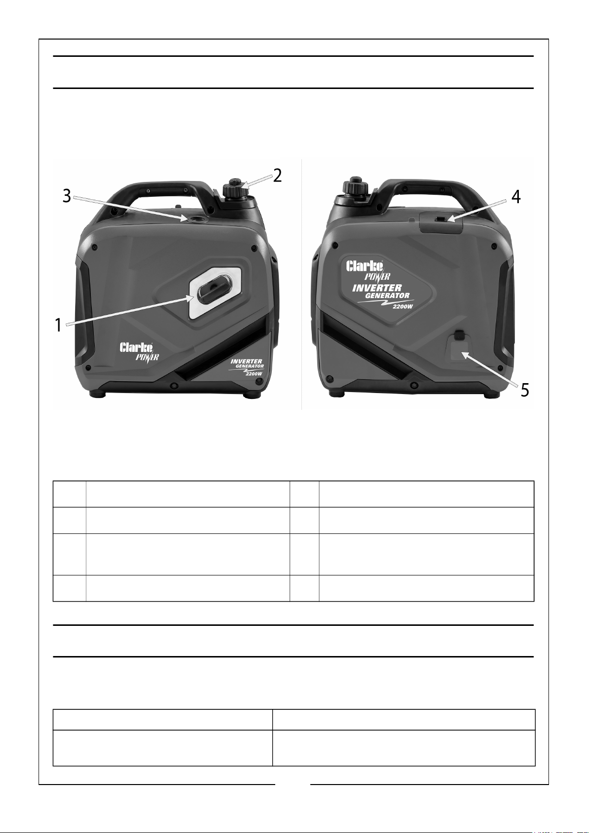
OVERVIEW - GENERAL COMPONENTS
NO DESCRIPTION NO DESCRIPTION
1 Recoil Starter 4 Spark Plug Cover
2 Fuel Cap/Fuel Tank Vacuum Relief
Valve
3 Fuel Gauge
5 Oil Filler Cap Cover
UNPACKING AND ASSEMBLY
Unpack your generator and check the following items are present. Should there be
any missing or damaged during transit contact your CLARKE dealer.
1 x 2200 Watt Inverter Generator 1 x 12 Volt Crocodile Clip Lead Assembly
1 x Spark Plug Box Spanner with
Lever
1 x Oil Funnel
8
Parts & Service: 020 8988 7400 / E-mail: [email protected] or [email protected]
Page 9
BEFORE USING THE GENERATOR
IMPORTANT: Generators should ALWAYS be earthed. Make sure you
earth the generator.
Before using your generator check that the generator is:
• In good condition and free from any damage.
• Clean and free from fuel or oil spillage.
• Correctly located for use (see page 3).
• Correctly earthed.
• Free from leakage.
NOTE: To avoid accidental spillage of fuel, use a funnel to fill the fuel tank. If
fuel is spilled it must be removed from the unit before attempting to
start the engine.
EARTHING
WARNING: IT IS ADVISABLE TO PROPERLY EARTH YOUR
GENERATOR BEFORE STARTING, USING A WIRE AND A SMALL
METAL EARTH SPIKE. THE WIRE AND EARTH SPIKE ARE NOT
SUPPLIED WITH THIS UNIT.
An earth rod and cable can be purchased at your local camping or electrical supplier,
or alternatively an earth rod can be made, and it is suggested you get advice from a
qualified electrician.
The cable used should be insulated and a maximum length of 1 metre and a minimum
of 1.0mm2 to carry a 10amp load.
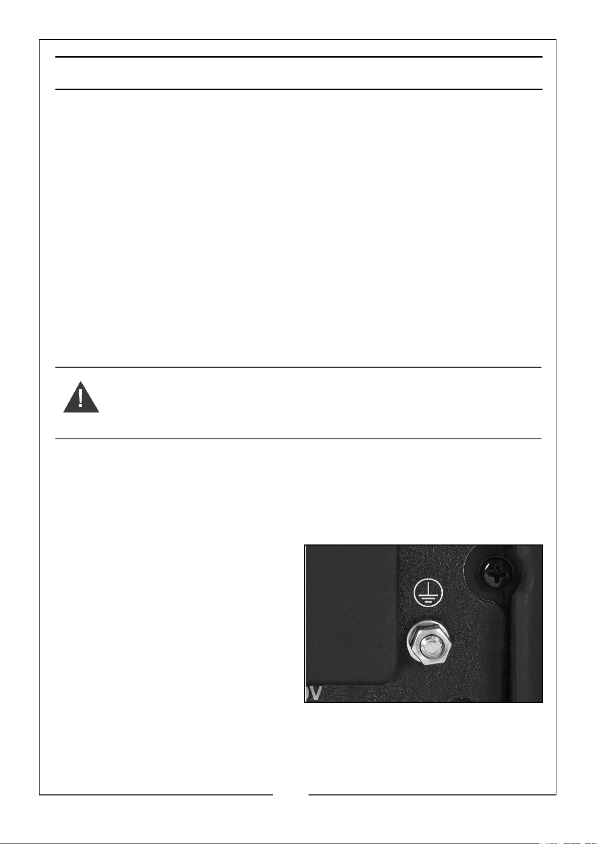
Attach the cable to the generator at the
earthing point (shown on the right).
Connect the other end of the cable to a
steel or copper earth rod. If you have
purchased a rod, make sure you connect
it in accordance with the installation
instructions supplied with the rod.
When pushing the rod into the ground
the generator must not be running and it
is suggested that the rod is pushed into
the ground by at least 100 mm.
Earthing of generators is covered in BS7430:2011. If you have any doubts about this
subject consult a qualified electrician.
9
Parts & Service: 020 8988 7400 / E-mail: [email protected] or [email protected]
Page 10
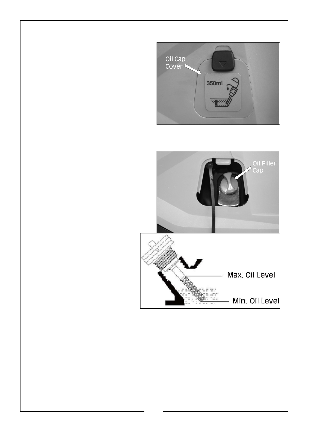
CHECKING & ADDING ENGINE OIL
1. Place the generator on a level surface
and check the oil level as follows.
NOTE: The oil reservoir capacity is
350ml
2. Remove the oil cap cover located on
the side of the generator.
3. Turn the oil filler cap anti-clockwise
and remove from the oil reservoir,
wipe the dipstick with a clean cloth.
4. Insert the dipstick back into the oil
filler tube and then remove it again.
5. If the oil is below the Min. level
on the dipstick, top up the oil
reservoir with fresh oil using
the oil funnel.
• DO NOT fill above the max
level mark.
• We recommend the use of
SAE10W-30 oil in this
generator. (CLARKE part
number 3050845)
• DO NOT tilt the generator when adding engine oil. This could result in
overfilling and damage to the engine.
6. Replace the oil filler cap.
7. Replace the oil cap cover.
10
Parts & Service: 020 8988 7400 / E-mail: [email protected] or [email protected]
Page 11
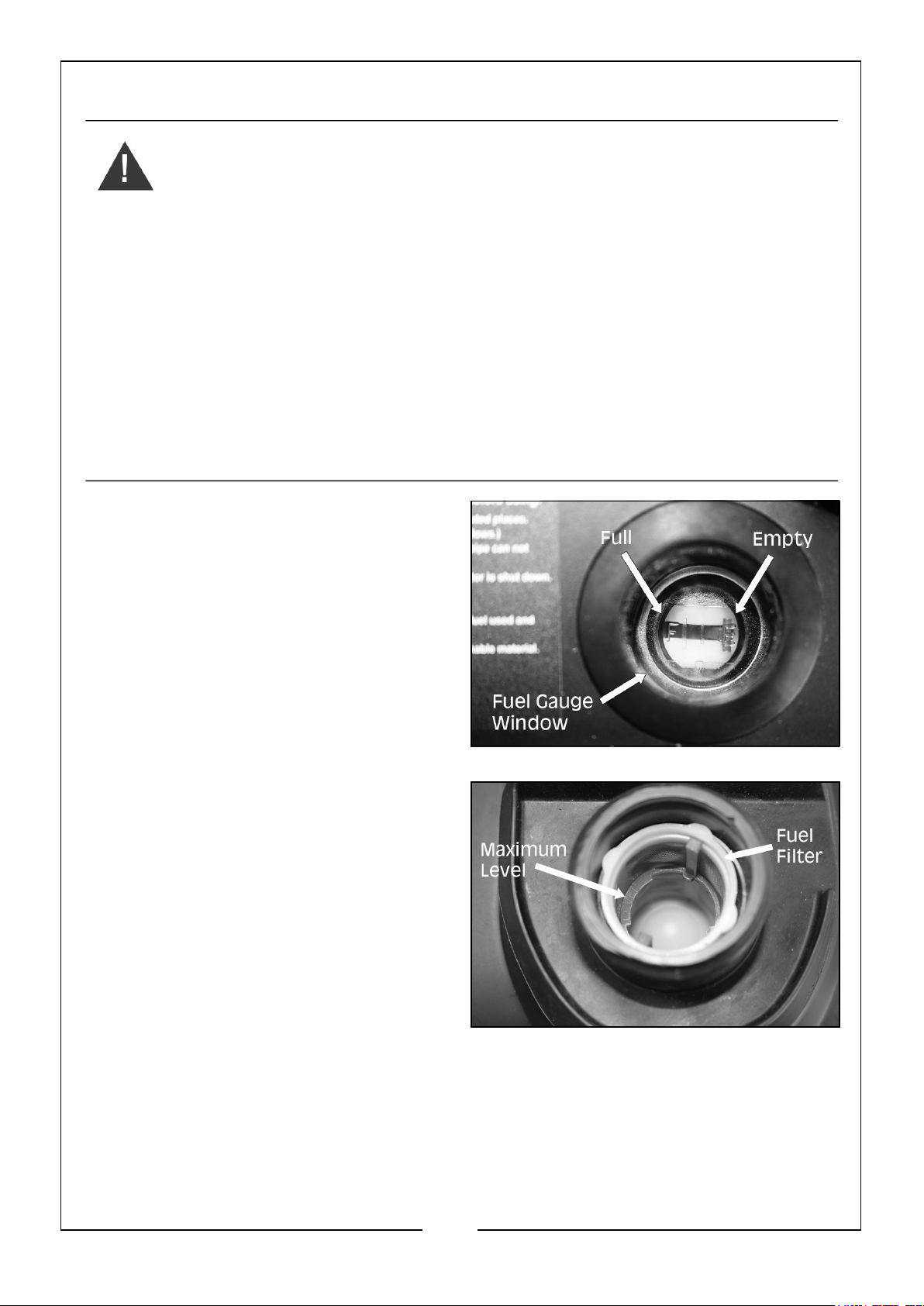
CHECKING & ADDING FUEL
WARNING: MAKE SURE THERE IS FUEL IN THE TANK WHEN USING
THE GENERATOR. RUNNING OUT OF FUEL OR STOPPING THE
ENGINE SUDDENLY WITH A LOAD CONNECTED COULD CAUSE
SERIOUS DAMAGE.
WARNING: FUEL IS HIGHLY FLAMMABLE AND POISONOUS.
WARNING: SEE GENERAL SAFETY RULES ON PAGE 4 AND READ
THEM CAREFULLY BEFORE REFUELING.
WARNING: DO NOT FILL ABOVE THE TOP OF THE FUEL FILTER OR IT
MAY OVERFLOW WHEN THE FUEL HEATS UP AND EXPANDS.
WARNING: WIPE UP ANY SPILLED FUEL IMMEDIATELY.
WARNING: AFTER REFUELING, MAKE SURE THE FUEL FILLER CAP IS
TIGHTENED SECURELY.
RECOMMENDED FUEL
Your generator has been designed to use
regular unleaded petrol with a octane
number of 86 or higher.
1. Check the fuel level via the fuel
gauge window located on top of the
generator. A red bar will show the
fuel quantity in the tank.
NOTE: The fuel tank capacity is 5.6
Litres (Safe Fuel Level).
2. Open the fuel filler cap located on top
of the generator.
3. Slowly add fuel to the fuel tank.
• DO NOT overfill the fuel tank.
4. Replace the fuel filler cap securely.
5. Clear up any spillages.
11
Parts & Service: 020 8988 7400 / E-mail: [email protected] or [email protected]
Page 12
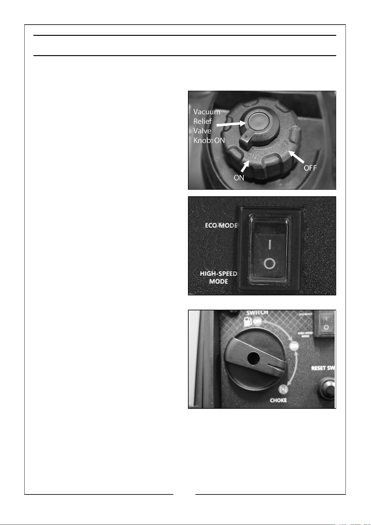
USING YOUR GENERATOR
STARTING THE ENGINE
1. Remove all connections from the AC
& DC sockets.
2. Check that the generator is correctly
earthed, see pages 9 - 10
3. Hold the fuel tank cap so that it will
not move and turn the fuel tank
vacuum relief valve knob to the ‘ON’
position.
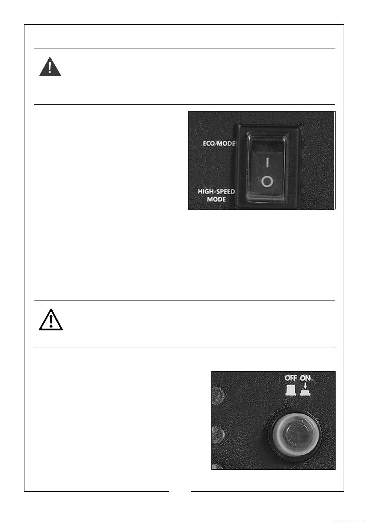
4. Set the Economy Control Switch to
the ‘O’ - HIGH SPEED MODE’
position.
5. Move the OFF/ON/CHOKE Fuel
Switch clockwise to the ‘CHOKE’
position.
12
Parts & Service: 020 8988 7400 / E-mail: [email protected] or [email protected]
Page 13
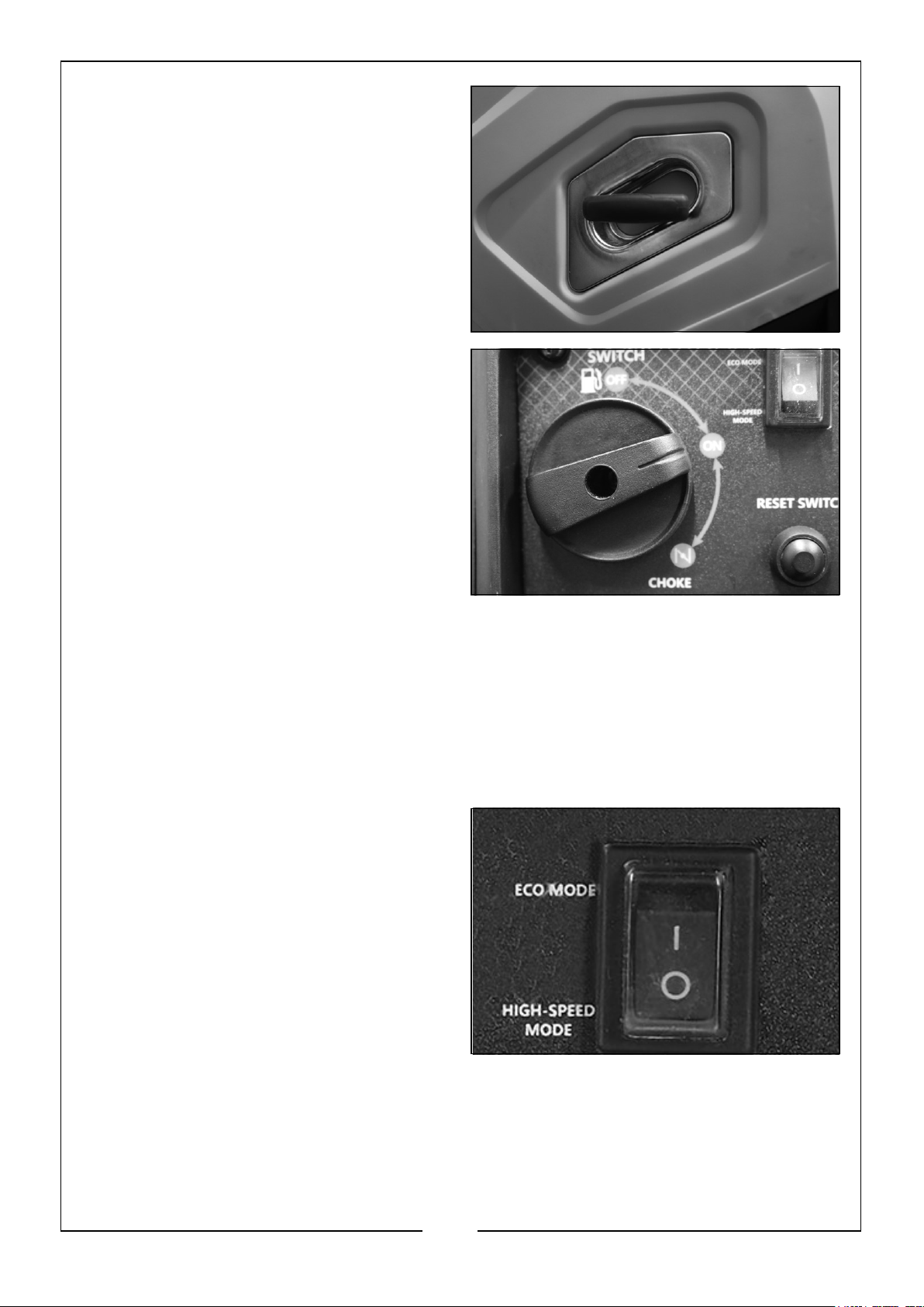
6. Hold the recoil starter handle firmly
and pull lightly until you start to feel
resistance and then pull up sharply to
start the engine.
NOTE: You may have to do this more
than once.
NOTE: NEVER let the handle snap
back.
7. Once the engine has started, slowly
turn the fuel switch to the ‘ON’
position.
NOTE: Allow the generator to run for
several minutes before
attempting to connect any
electrical devices. This allows the
generator to stabilize its speed
and temperature.
NOTE: When you first start the
generator, the overload indicator (see item 4, page 7) may light up for a
few seconds, this is normal. If the overload indicator is still lit after 5
seconds, stop the engine and contact your CLARKE dealer or the
CLARKE Service Department.
ECONOMY CONTROL SWITCH
‘I’ (ECO MODE):
Recommended to minimize fuel
consumption and further reduce noise
levels when no load is applied to the
generator. Engine speed varies with the
load.
‘O’ (HIGH-SPEED MODE):
The engine will run at the rated speed
regardless of whether a load is
13
Parts & Service: 020 8988 7400 / E-mail: [email protected] or [email protected]
Page 14
connected or not. The switch should be in the ‘O’ position if you are using electrical
devices that require a large starting current such as compressors or water pumps.
CAUTION: THE ECONOMY CONTROL DOES NOT WORK EFFECTIVELY
IF THE ELECTRICAL APPLIANCE REQUIRES ‘BURSTS’ OF POWER.
CAUTION: TURN THE ECONOMY CONTROL FEATURE OFF WHEN
CONNECTING HIGH LOAD APPLIANCES OR WHEN CONNECTING TO
THE DC OUTPUT.
CONNECTING ELECTRICAL DEVICES
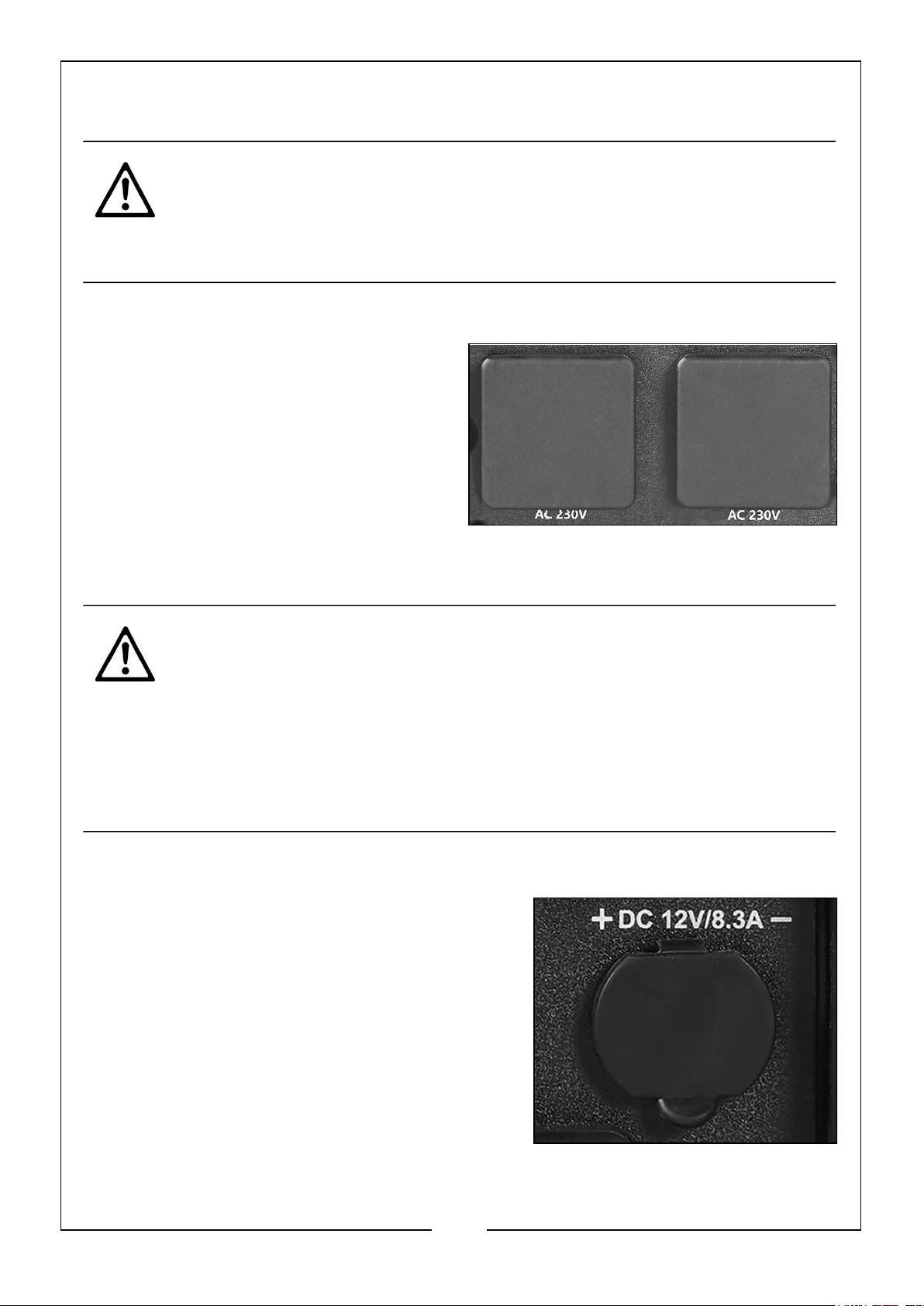
The generator can supply both 230V AC
and 12V DC.
AC POWER
1. Start the engine. See pages 12-13.
2. Make sure the appliance is turned off
before connecting it to the generator.
3. Connect the appliance to the generator using one of the two 3 Pin 13A 230V AC
outlets.
CAUTION: MAKE SURE THAT THE APPLIANCE BEING CONNECTED IS
IN GOOD WORKING ORDER, IF IT BEGINS TO ACT ABNORMALLY OR
STOPS SUDDENLY, DISCONNECT IT FROM THE GENERATOR
CAUTION: MAKE SURE THE APPLIANCE DOES NOT EXCEED THE
MAXIMUM RATED LOAD FOR THE GENERATOR.
CAUTION: ANY DEVICE WHICH CONTAINS AN INDUCTIVE LOAD E.G.
DEVICES THAT CONTAIN A MOTOR MAY REQUIRE MORE CURRENT
ON STARTUP.
DC POWER
1. Set the economy control switch to ‘O’.
2. Start the generator. See pages 12-13.
3. Make sure the appliance is turned off before
connecting it to the generator.
4. Lift the cover and connect the 12V appliance
(max 8.3A) to the generator.
14
Parts & Service: 020 8988 7400 / E-mail: [email protected] or [email protected]
Page 15
DC POWER (TOPPING UP CAR BATTERIES)
WARNING: FOR YOUR SAFETY PERFORM THE FOLLOWING
INSTRUCTIONS IN THE ORDER SHOWN.
WARNING: YOU SHOULD ONLY USE THIS GENERATOR TO ‘TOP UP’
THE BATTERY AS TRYING TO CHARGE A COMPLETELY FLAT BATTERY
MAY CAUSE THE FUSE TO BLOW.
1. Set the Economy Control Switch to
the ‘O’ - HIGH SPEED MODE’
position.
2. Start the generator. See pages 12 -
13.
3. Connect the battery charging leads to
the battery.
• Make sure you clamp the red wire
to the positive (+) terminal and
the black wire to the negative (-)
terminal of the battery.
4. Connect the battery charging lead to the generators DC Power socket.
• The battery will begin to charge
5. Monitor the voltage across the battery regularly during charging and disconnect
the battery when the voltage reaches 14.4 volts.
CAUTION: WHEN DISCONNECTING THE BATTERY, ALWAYS
DISCONNECT THE NEGATIVE LEAD FIRST.
CAUTION: DO NOT ALLOW THE RED AND BLACK CLAMPS TO TOUCH
WHILE STILL CONNECTED TO THE GENERATOR.
DC PROTECTOR
The DC protector turns ‘OFF’ automatically
when the electrical device connected to the
generator is operating and the current is above
the rated flow.
To use this device again, turn the DC protector
to the ‘ON’ position.
NOTE: Reduce the load of the connected
device below the specified rated output
of the generator if the DC protector
15
Parts & Service: 020 8988 7400 / E-mail: [email protected] or [email protected]
Page 16
turns ‘OFF’. If the DC protector turns off again, stop using the device
immediately.
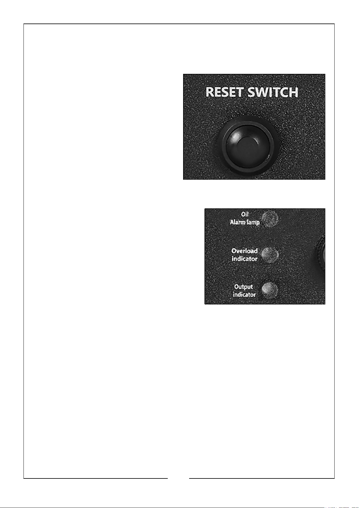
OVERLOAD RESET
If the overload protector activates, wait
for a few minutes and then press the
reset switch shown on the right.
INDICATOR LIGHTS
OUTPUT
The output indicator (Green) will remain on
during normal operation.
OVERLOAD
The overload indicator (Red) will light up if
there is an overload or a short circuit in the
connected appliance.
If this happens, proceed as follows:
1. Turn off any connected electrical devices
and stop the generator.
2. Reduce the total wattage of connected electric devices to within the rated output
of the generator.
3. Check air inlet and around the control unit. If any blockages are found, remove
them.
4. After checking, restart the generator.
OIL ALERT
The oil alert indicator (Red) will light up when the oil level is low.
• To add oil, follow the instructions on page 10 - 11.
16
Parts & Service: 020 8988 7400 / E-mail: [email protected] or [email protected]
Page 17

SHUTTING DOWN THE GENERATOR
To stop the generator simply turn the OFF/ON/
CHOKE Fuel Switch anti-clockwise to the ‘OFF’
position, as shown.
NOTE: Turn off any electric devices.
NOTE: Set the economy control switch to
the ‘O’ - HIGH SPEED MODE’
position.
1. Disconnect any electric devices.
2. Turn the OFF/ON/CHOKE Fuel Switch to
the ‘OFF’, as shown.
3. Hold the fuel tank cap so that it will
not move and turn the fuel tank
vacuum relief valve knob to the ‘OFF’
position.
CAUTION: ALLOW THE GENERATOR TO COOL FOR SEVERAL
MINUTES BEFORE TOUCHING AREAS THAT BECOME HOT DURING
USE.
NOTE: Be sure the engine switch and the fuel tank vacuum relief valve are in the
‘OFF’ positions when stopping, transporting and storing the generator.
17
Parts & Service: 020 8988 7400 / E-mail: [email protected] or [email protected]
Page 18
MAINTENANCE
CHANGING ENGINE OIL (EVERY 20 HOURS OF USE)
CAUTION: PROLONGED EXPOSURE TO USED ENGINE OIL IS
DANGEROUS, ALWAYS WASH YOUR HANDS THOROUGHLY AFTER
HANDLING USED ENGINE OIL.
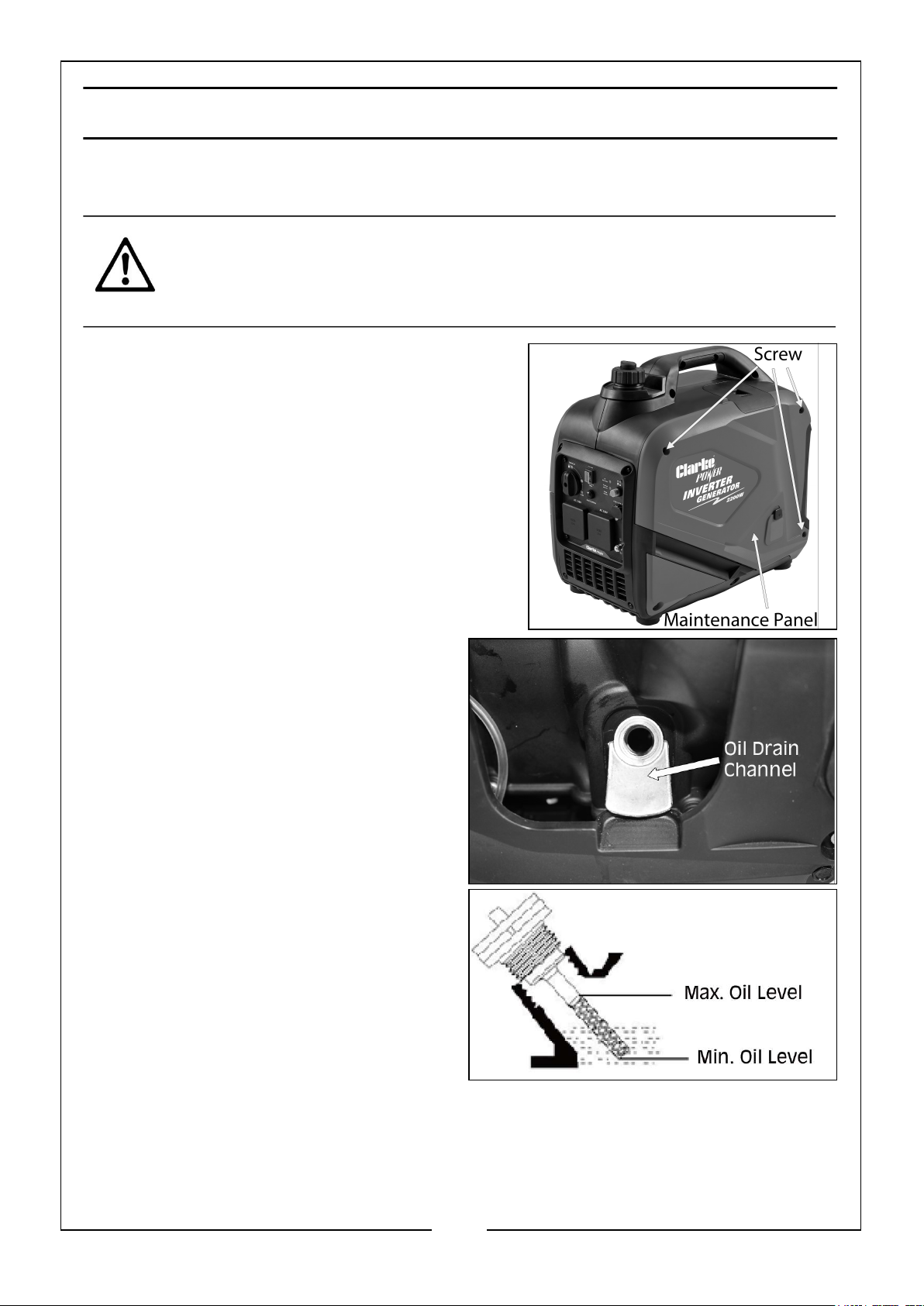
1. Unscrew the 3 fixing screws on each corner
and remove the maintenance panel shown
on the right.
2. Turn the oil filler cap anti-clockwise
and remove from the oil tank.
3. Tilt the generator to allow the oil to
drain out of the oil reservoir into a
suitable container via the drain
channel until empty.
NOTE: You may need assistance with
this step as the generator is
heavy.
4. Fill the oil reservoir with fresh oil.
• DO NOT fill above the max level
mark (0.35 litres)
• We recommend the use of
SAE10W-30 oil in this generator.
(CLARKE part number 3050845)
5. Replace the oil filler cap and
maintenance panel.
18
Parts & Service: 020 8988 7400 / E-mail: [email protected] or [email protected]
Page 19
ENVIRONMENTAL PROTECTION
One of the most damaging sources of pollution is oil. DO NOT throw away used
engine oil in with your domestic waste or down drains and sinks. Place it in a leak
proof container and dispose of it according to local regulations.
CHANGING AIR FILTER (EVERY 50 HOURS OF USE)
WARNING: DO NOT USE FLAMMABLE SOLVENTS OR PETROL TO
CLEAN THE AIR FILTER.
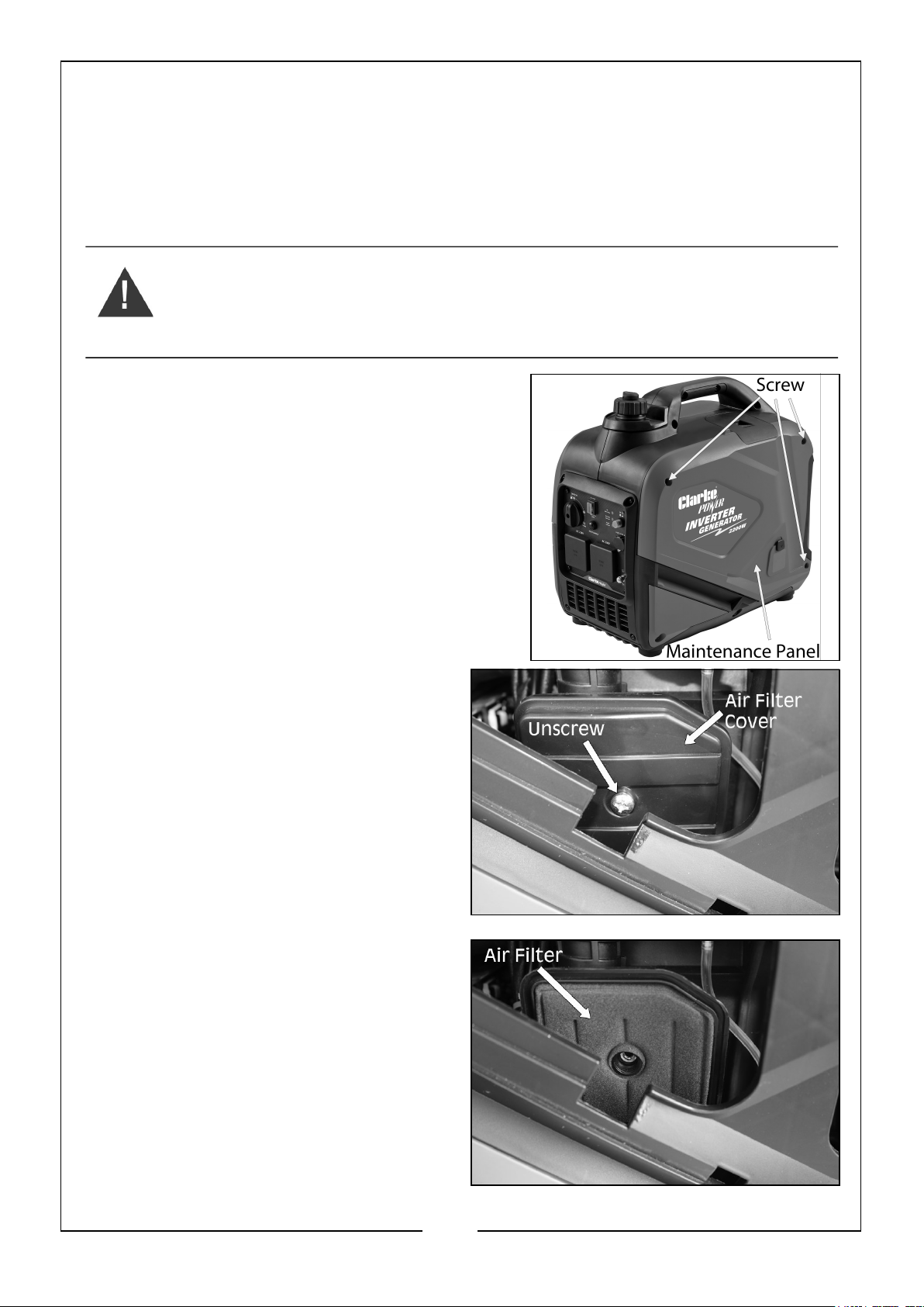
1. Unscrew the 3 fixing screws on each corner
and remove the maintenance panel shown
on the right.
2. Remove the air filter cover screw,
shown on the right.
3. Remove the air filter cover.
4. Remove the air filter element.
5. If the air filter is damaged contact
the CLARKE spare parts department
for a replacement.
• If the filter is dirty, wash it in a
solution of warm water and mild
detergent and then rinse
thoroughly.
19
Parts & Service: 020 8988 7400 / E-mail: [email protected] or [email protected]
Page 20
• Leave the filter to dry completely. Once it is dry immerse the filter in clean
engine oil and squeeze the filter to remove excess oil.
6. Replace the filter into its original position and replace and secure the air filter
cover.
CHANGING SPARK PLUG (EVERY 50 HOURS OF USE)
CAUTION: ALLOW THE ENGINE TO COOL BEFORE REMOVING THE
SPARK PLUG.
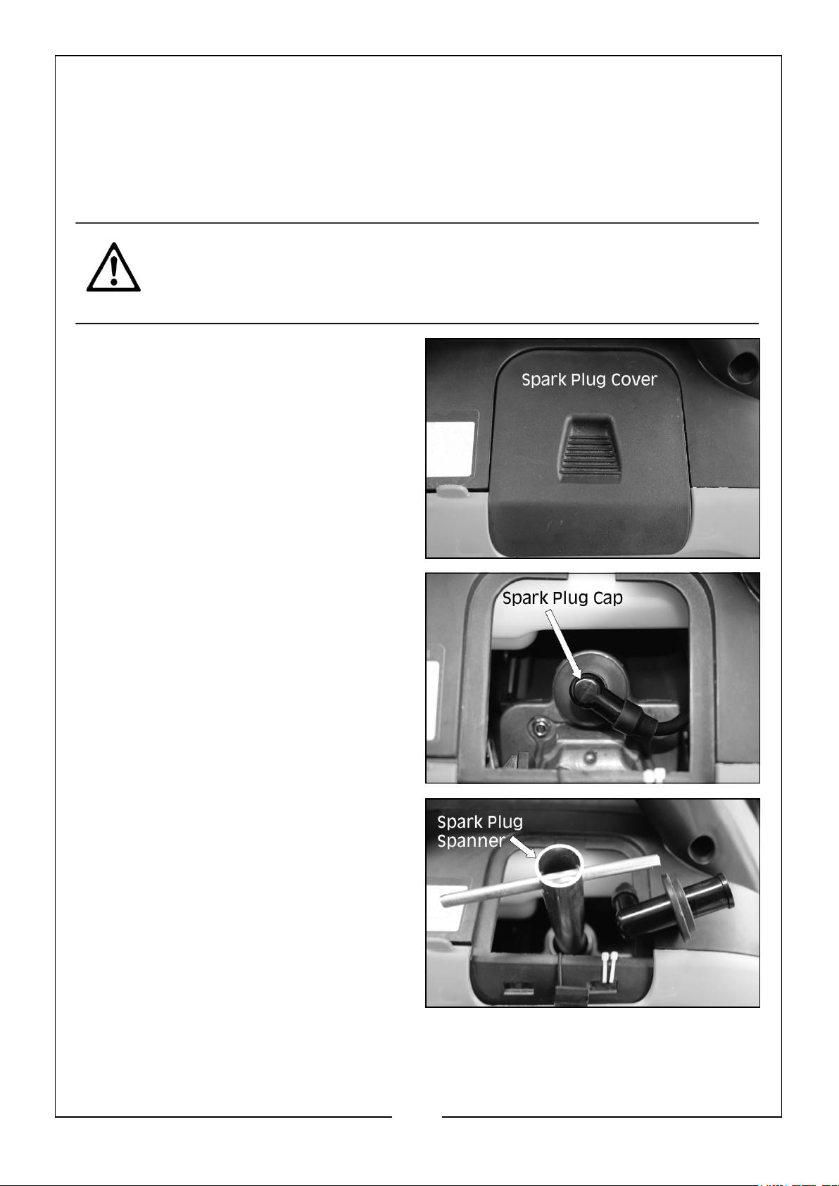
1. Remove the spark plug cover panel
located on top of the generator.
2. Remove the spark plug cap from the
spark plug.
3. Fit the spark plug box spanner over
the spark plug as shown.
4. When the spark plug has been
removed, check for discoloration and use a wire brush to remove any carbon build
up.
20
Parts & Service: 020 8988 7400 / E-mail: [email protected] or [email protected]
Page 21
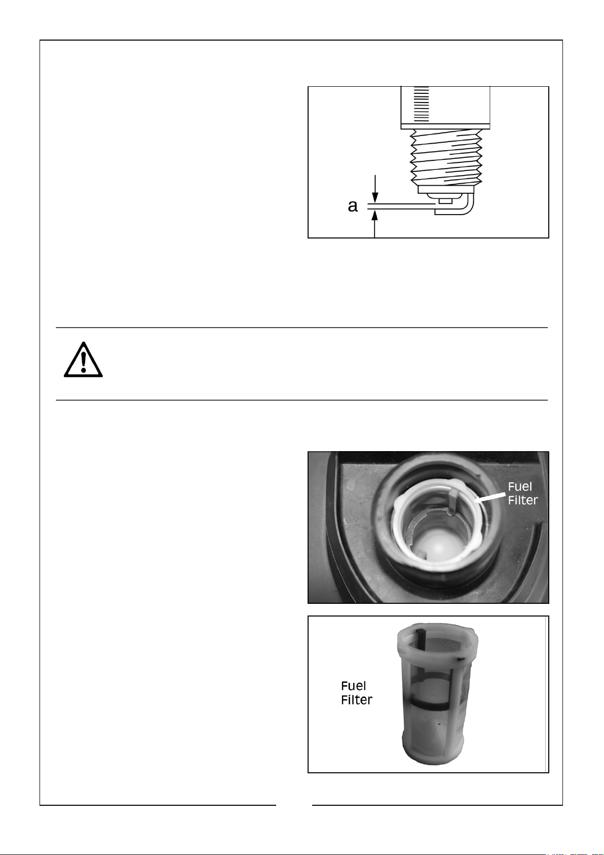
5. Check the spark plug gap (a) with a
feeler gauge, it should be between
0.6 and 0.7 mm.
• Adjust if necessary.
6. Check the overall condition of the
spark plug and replace if damaged.
NOTE: Spark plugs are available from
CLARKE Spare Parts department
020 8988 7400.
7. Reinstall the spark plug and replace the spark plug cap and top cover.
CLEAN FUEL TANK FILTER (EVERY 100 HOURS OF USE OR
EVERY 6 MONTHS)
CAUTION: ALLOWING PETROL TO SIT IN THE FUEL TANK FOR LONG
PERIODS OF TIME CAN MAKE IT DIFFICULT TO START THE
GENERATOR IN THE FUTURE. NEVER STORE THE GENERATOR FOR
EXTENDED PERIODS OF TIME WITH FUEL IN THE TANK.
Just inside the fuel tank is a fuel filter. Check this filter periodically and remove any
contaminants which may have accumulated.
1. Remove the fuel tank cap.
2. Lift out the filter inside.
3. Clean the filter with solvent. If the
filter is damaged, contact CLARKE
Spare Parts department 020 8988
7400 for a replacement.
4. Replace the filter and fuel tank cap.
21
Parts & Service: 020 8988 7400 / E-mail: [email protected] or [email protected]
Page 22
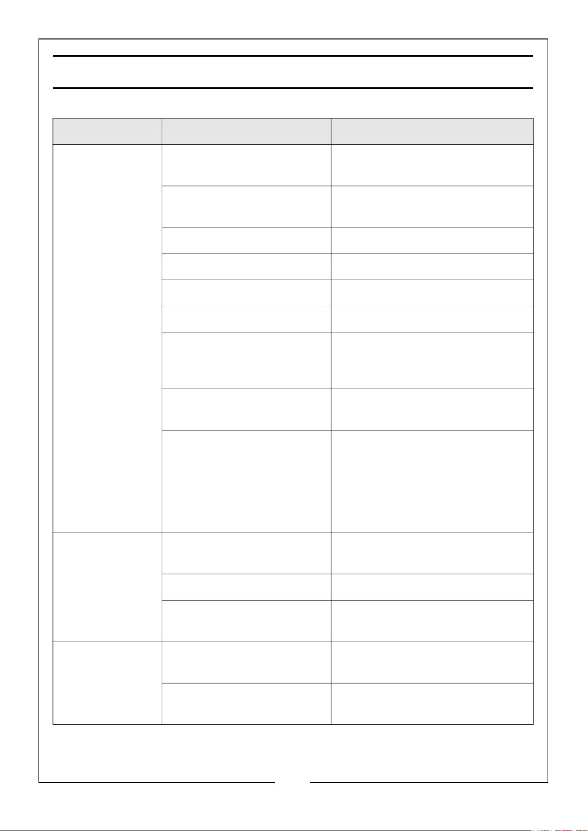
TROUBLESHOOTING
PROBLEM CAUSE SOLUTION
Engine does not
start
OFF/ON/CHOKE Fuel Switch
in OFF position
Fuel tank is filled with
contaminated or old fuel
Not enough oil in crankcase Add or replace oil
Air filter is dirty Clean or replace air filter
Spark plug is dirty Clean spark plug
Spark plug is broken Replace spark plug
Generator is not on level
surface
Engine needs maintenance Contact the CLARKE service
Generator was tilted when
adding oil or shipped side
down
Set OFF/ON/CHOKE Fuel Switch to
CHOKE position
Change the fuel in the tank
Move generator to a level surface
to prevent low oil shutdown from
triggering
department for more information
Remove spark plug, turn engine
switch to the OFF position then pull
recoil starter four (4) times to
remove oil from the combustion
chamber. Replace spark plug and
restart engine
Engine Stops Fuel tank vacuum relief valve
on OFF position
Not enough oil in crankcase Add or change oil
Engine is out of fuel Check fuel gauge and add fuel if
Blue smoke in
exhaust
Parts & Service: 020 8988 7400 / E-mail: [email protected] or [email protected]
Generator inclined, oil has
entered combustion chamber
To much oil has been added
to the crankcase
22
Turn fuel tank vacuum relief valve
to the ON position
needed
Move generator to a level position
Drain excess oil
Page 23
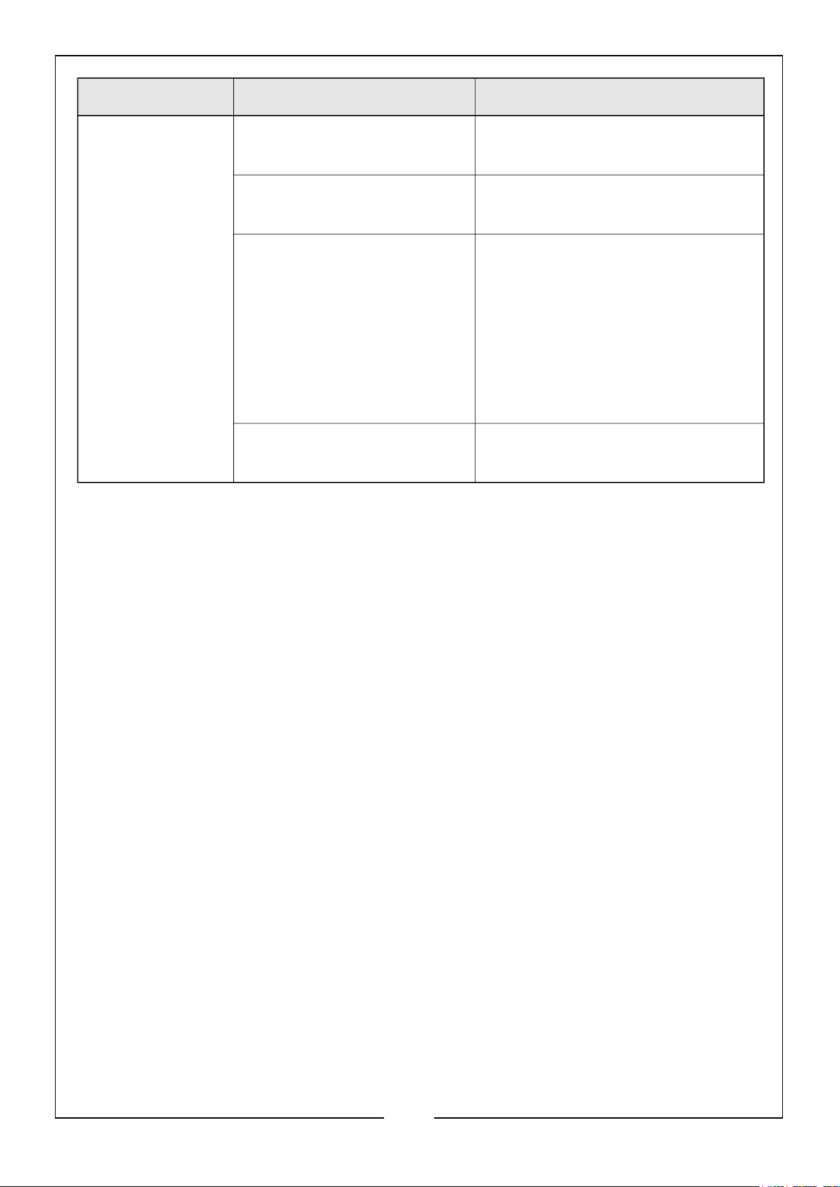
PROBLEM CAUSE SOLUTION
Generator runs
but does not
Bad connecting wires/cables If using an extension cable, try a
different one
support all
electrical devices
connected
Bad electrical device
connected to generator
Generator is overloaded,
(overload light is on).
Try connecting a different device
Perform these steps:
1: Turn off all electrical devices
2: Unplug all electrical devices
3: Shut down the engine
4: Wait several minutes and then
restart the engine
5: Try connecting fewer electrical
loads to the generator
Short circuit in one of the
connected devices
Try disconnecting any faulty or
short circuited electrical loads
If this does not solve your problem, please contact the CLARKE Service Department.
23
Parts & Service: 020 8988 7400 / E-mail: [email protected] or [email protected]
Page 24
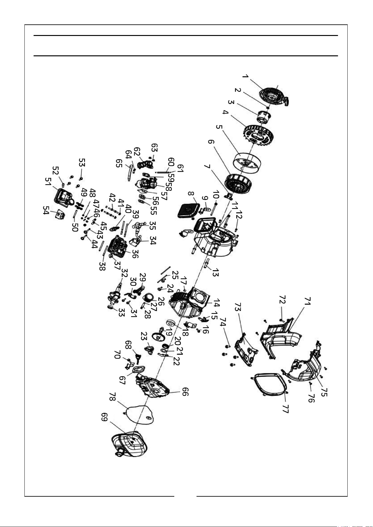
EXPLODED DIAGRAM - ENGINE
24
Parts & Service: 020 8988 7400 / E-mail: [email protected] or [email protected]
Page 25
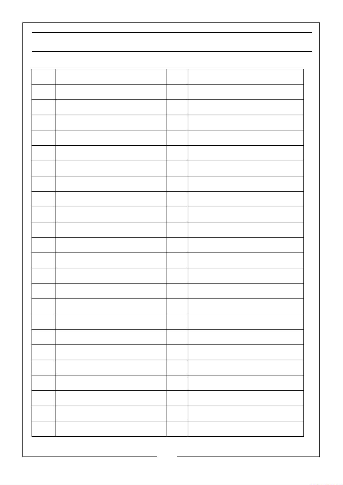
PARTS LIST - ENGINE
No Description No Description
1 Recoil Starting Assembly 24 Valve Lifter
2 Nut (M12 x 1.25mm) 25 Push Rod
3 Starting Pulley 26 Piston
4 Flywheel 27 Circlip (Piston Pin)
5 Rotor 28 Piston Pin
6 Stator 29 Connecting Rod
7 35mm Flip-Flop 30 Big End
8 Air Filter 31 Bolt
9 Damping Base 32 Crankshaft
10 Bolt (M6 x 30mm) 33 Oil Seal
11 Recoil Starter Housing 34 Spark Plug Coil
12 Screw (5.5 x 12mm) 35 Spark Plug
13 Bolt (M6 x 88) 36 Cylinder Head
14 Crank Case 37 Exhaust Valve Gasket
15 Wire Clamp 38 Bolt (M6 x 88mm)
16 Bolt (M6 x 16) 39 Bolt (M6 x 88mm)
17 Location Pin 40 Spark Plug
18 Bearing 41 Nut (M6 x 8mm)
19 Camshaft Assembly 42 Bolt (M6 x 78mm)
20 Governor Gear Set 43 Intake Valve
21 Governor Arm Shaft Gasket 44 Exhaust Valve
22 Governor Arm 45 Valve Spring
23 Oil Alert Switch 46 Valve Collet
25
Parts & Service: 020 8988 7400 / E-mail: [email protected] or [email protected]
Page 26
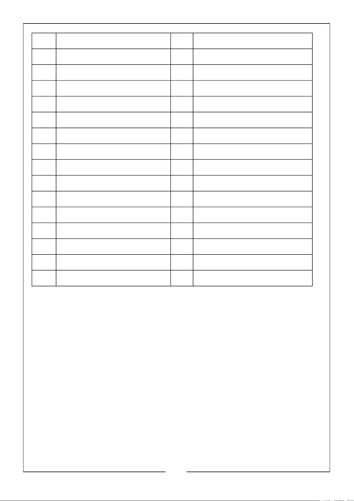
47 Bolt 63 Nut (M6 x 8mm)
48 Nut 64 Exhaust Pipe Connector
49 Valve Rocker Arm 65 Waste Pipe
50 Valve Rocker Arm Shaft 66 Crankcase Cover Set
51 Cylinder Head Cover 67 Oil Level Gauge Cover Plate
52 Exhaust Pipe Connector 68 Oil Gauge Set
53 Bolt 69 Muffler
54 Limit Plate 70 Bolt (M6 x 12mm)
55 Intake Gasket 71 Air Duct
56 Carburetor Insulation Board 72 Bolt (M6 x 20mm)
57 Carburetor Gasket 73 Lower Duct
58 Carburetor 74 Bolt (M6 x 12mm)
59 Air Filter Gasket 75 Air Duct
60 Fuel Pipe 76 Bolt (M5.5 x 12mm)
61 Tube Clip 77 Gasket
62 Air Filter Inlet Pipe 78 Muffler Heat Shield
26
Parts & Service: 020 8988 7400 / E-mail: [email protected] or [email protected]
Page 27
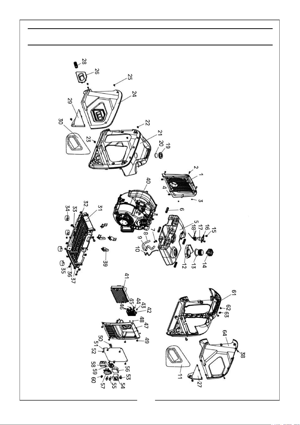
EXPLODED DIAGRAM - GENERATOR
27
Parts & Service: 020 8988 7400 / E-mail: [email protected] or [email protected]
Page 28
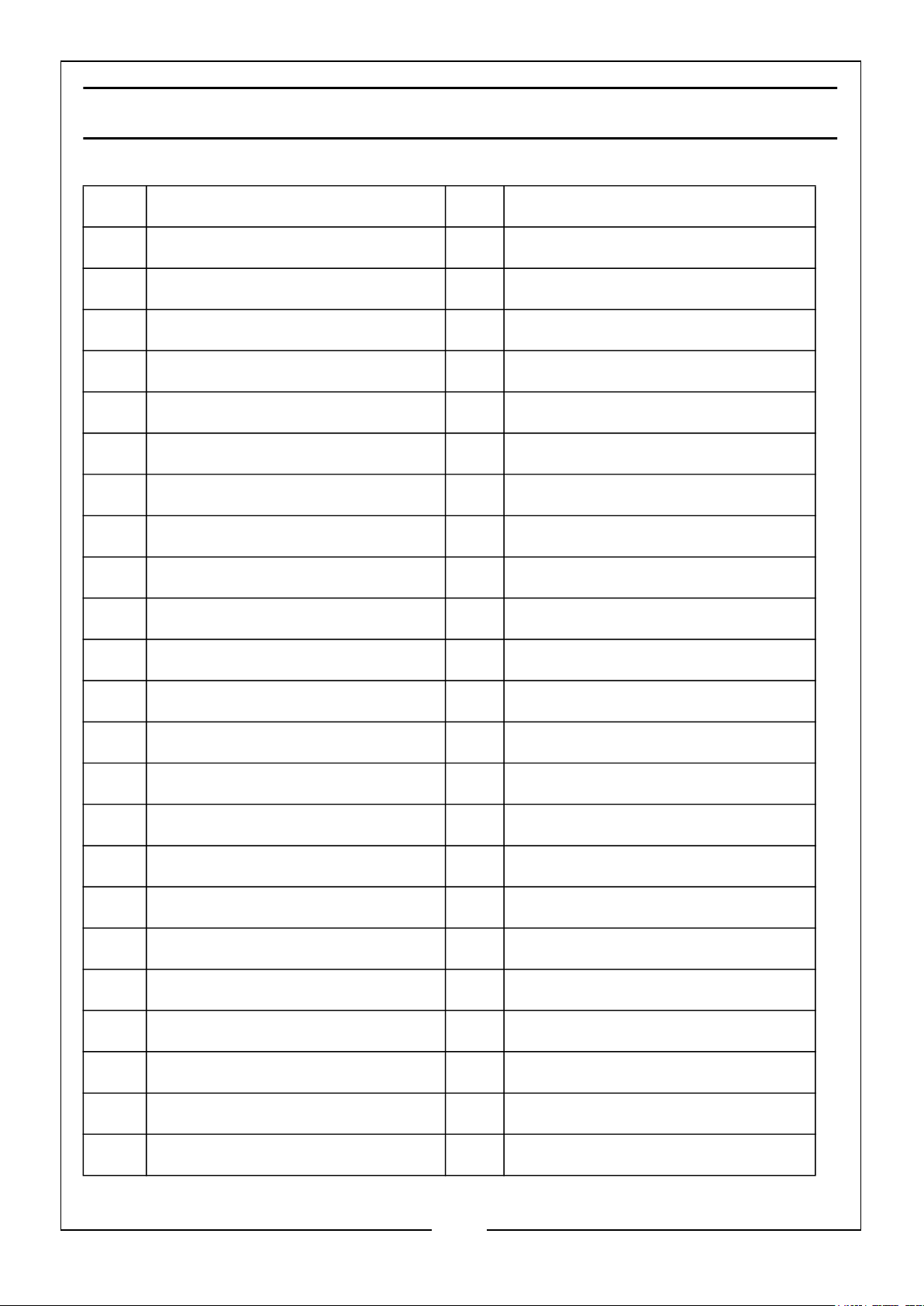
PARTS LIST - GENERATOR
No Description No Description
1 Rear Cover 24 Left Cover Plate
2 Screw (M5 x 16) 25 Screw (ST3 x10)
3 Bushing 26 Handle Trim Cover
4 Nut (M5) 27 Corner Piece Cover (Right)
5 Fuel Tank 28 Starting Handle
6 Rubber Gasket 29 Corner Piece Cover (Left)
7 Nozzle 30 Soundproofing Cotton
8 Fuel Pipe 31 Baseplate
9 Fuel Pipe 32 Nut (M6)
10 Throttle Cable 33 Nut (M6)
11 Soundproof Cotton 34 Rubber Feet
12 Gum Cover 35 Bolt
13 Fuel Tank Seal 36 Bushing
14 Fuel Tank Cap 37 Nut (M5)
15 Bolt (M6 x 12) 38 Screw (M5 x 16)
16 Pressing Plate (Oil Level) 39 Shockproof Foot
17 Fuel Meter 40 Engine Assembly
18 Fuel Meter 41 Inverter
19 Damping Ring 42 3 in 1 Switch
20 Sight-glass (Oil Level) 43 Locating Pin
21 Left Handle 44 Locating Pin
22 Screw (M5 x16) 45 Locating Pin
23 Bolt (M6 x 18) 46 Locating Pin
28
Parts & Service: 020 8988 7400 / E-mail: [email protected] or [email protected]
Page 29
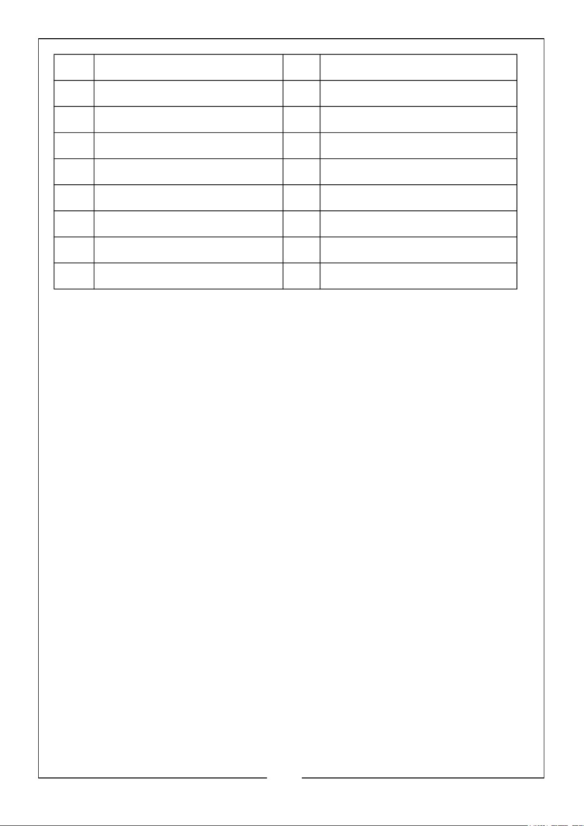
47 Panel Cover 56 Voltmeter
48 Locating Pin Cover 57 EU Socket
49 Screw (M5 x 16) 58 3 in 1 Indicator
50 Valve Cable Pressing Plate 59 Switching
51 Panel 60 Earth Bolt
52 Screw (M5 x 16) 61 Right Handle
53 Idling Switch 62 Screw
54 T Type Socket 63 Gasket
55 Socket (Connected to Grid) 64 Right Cover Plate
29
Parts & Service: 020 8988 7400 / E-mail: [email protected] or [email protected]
Page 30
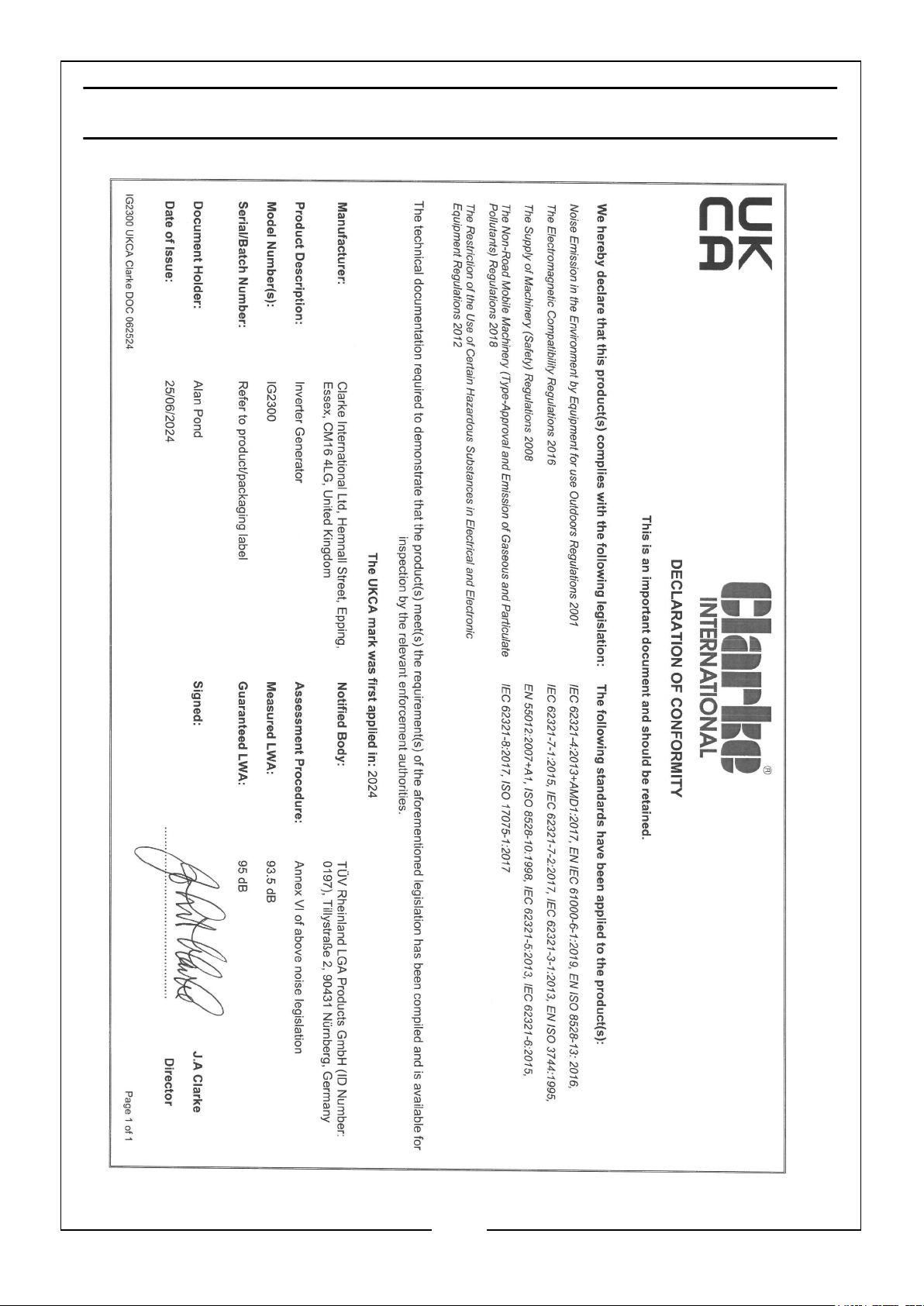
DECLARATION OF CONFORMITY -UKCA
30
Parts & Service: 020 8988 7400 / E-mail: [email protected] or [email protected]
Page 31
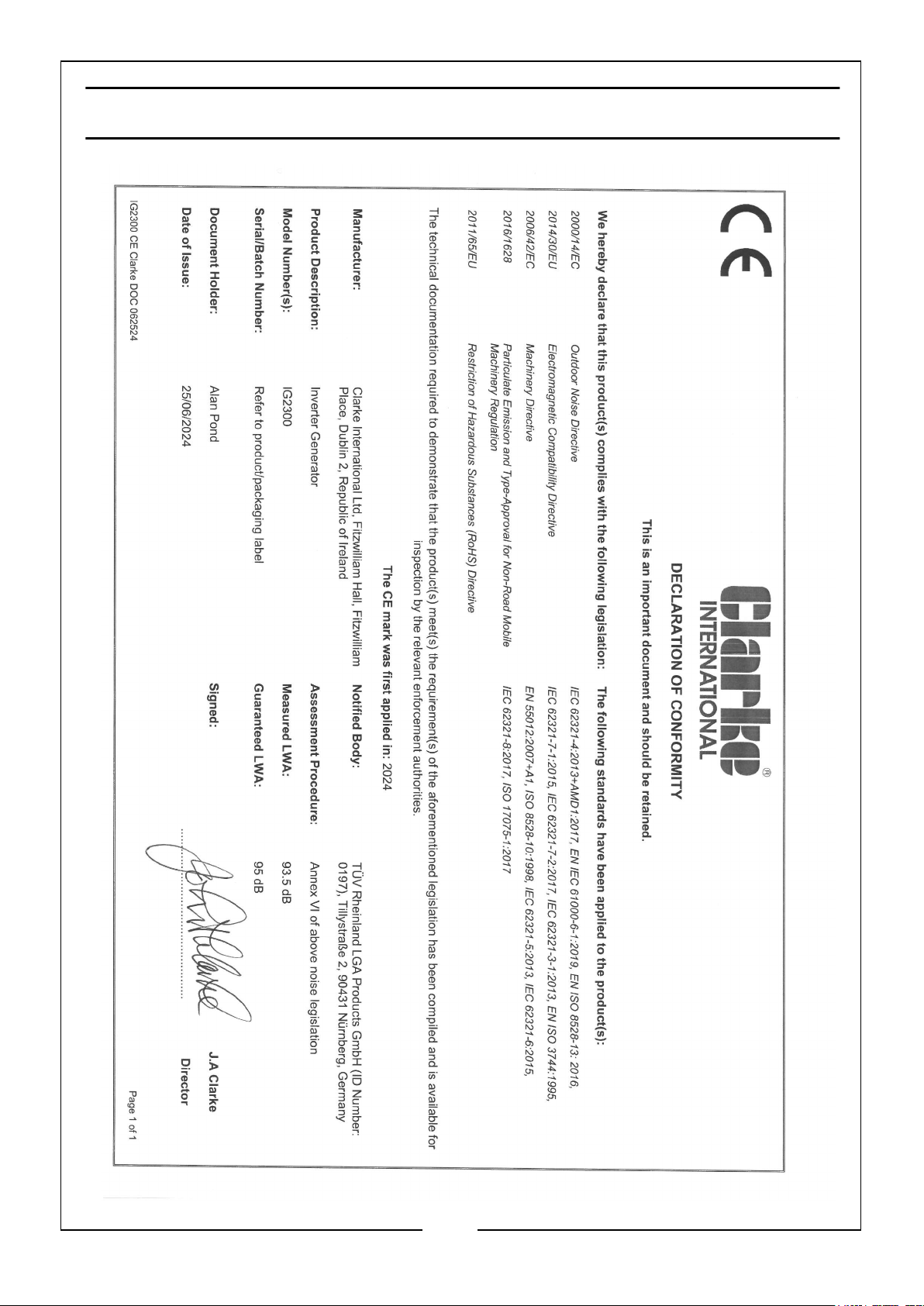
DECLARATION OF CONFORMITY -CE
31
Parts & Service: 020 8988 7400 / E-mail: [email protected] or [email protected]
Page 32

 Loading...