

Page 1

E
Operator's Manuals
EXT 311
(click here)
EXT 515
(click here)
Page 2
E
Division of
Operator's
Manual
READ THIS BOOK
This book has important information for the use and safe operation of this machine. Failure to read this
book prior to operating or attempting any service or maintenance procedure to your Clarke machine
could result in injury to you or to other personnel; damage to the machine or to other property could occur
as well. You must have training in the operation of this machine before using it. If your operator(s) cannot
read English, have this manual explained fully before attempting to operate this machine.
Si Ud. o sus operadores no pueden leer el Inglés, se hagan explicar este manual completamente antes
de tratar el manejo o servicio de esta máquina.
All directions given in this book are as seen from the operator’s position at the rear of the machine.
For new books write to: Clarke
®
, 2100 Highway 265, Springdale, Arkansas 72764.
EXT 311
Extractor
Form No. 70471A 11/02 Clarke® Printed in the U.S.A.
Page 3

CONTENTS OF THIS BOOK
Operator Safety Instructions .................................................................................. 1
Introduction and Machine Specifications .................................................................. 2
Controls and Machine Features ............................................................................... 3
How to Prepare the Machine for Operation .............................................................. 4
Instructions for Connection to the Power Supply - 120V
Extension Cords - 120V ............................................................................. 5
Instructions for Connection to the Power Supply - 230V
Extension Cords - 230V .......................................................................................... 6
Machine Operating Instructions ............................................................................... 7
How to Clean an Area of Carpet ..................................................................7
How To clean a Larger Area of Carpet .........................................................7
Maintenance ........................................................................................................... 8
After Each Use of the Machine ................................................................... 8
How to Prevent Damage from Freezing Temperatures ................................. 9
The Pump and Vacuum Motor ................................................................... 9
How To Check The Commutator and The Carbon Brushes .......................... 10
How to Correct Problems in the Machine ................................................................. 11
Machine Variables and Accessories ........................................................................12
Ext-311 Assembly Drawing .................................................................................... 14
Parts List ................................................................................................15
Ext -311 Base Assembly Drawing ...........................................................................16
Parts List ................................................................................................17
Ext-311 Solution Tank Assembly Drawing & Parts List ........................................... 18
Ext-311 Hose Assembly Drawing & Parts List .........................................................19
Ext-311 Pump Drawing & Parts List ........................................................................ 20
Motor Drawing & Parts List 120V ............................................................................21
Motor Drawing & Parts List 230V ............................................................................22
Electrical Schematic 120V ...................................................................................... 23
Wiring Diagram ....................................................................................................... 24
Electrical Schematic 230V ...................................................................................... 25
Wiring Diagram ....................................................................................................... 26
Page 2 Clarke
®
Ext -311 Owner's Manual
Page 4
OPERATOR SAFETY INSTRUCTIONS
WARNING AVERTISSEMENT ADVERTENCIA
For the safe operation of this machine, read and understand all warnings and cautions.
DANGER means: Severe bodily injury or death can occur to you or other personnel if
the DANGER statements found on your machine or in your Owner's
Manual are ignored or are not adhered to. Read and observe all
DANGER statements found in your Owner's Manual and on your
machine.
WARNING means : Injury can occur to you or to other personnel if the WARNING
statements found on your machine or in your Owner's Manual are
ignored or are not adhered to. Read and observe all WARNING
statements found in your Owner's Manual and on your machine.
CAUTION means: Damage can occur to the machine or to other property if the
CAUTION statements found on your machine or in your Owner's
Manual are ignored or not adhered to. Read and observe all
CAUTION statements found in your Owner's Manual and on
your machine.
DANGER: Machines can cause an explosion when operated near flammable materials and vapors. Do not
use this machine with or near fuels, grain dust, solvents, thinners, or other flammable materials.
DANGER: Do not immerse. To reduce the risk of an electric shock, use only on a carpet that has been
moistened by a cleaning process. Protect the machine from rain. Keep the machine in a dry
building. Always clean the machine with a clean dry cloth.
WARNING: You must have training in the operation of this machine before using it. READ THE
INSTRUCTION BOOK FIRST.
WARNING: Always use a three-wire electrical system connected to the electrical ground. For maximum
protection against electric shock, use a circuit that is protected by a ground fault circuit
interrupter. Consult your electrical contractor.
WARNING: To prevent electric shock, always remove the electrical plug from the electrical outlet before
doing any repairs or maintenance to this machine.
WARNING: Do not use this machine as a step or furniture. Injury could occur to the operator.
WARNING: To avoid serious injury, use proper lifting procedures when lifting the machine.
WARNING: Maintenance and repairs must be done by authorized personnel only.
WARNING: Keep all fasteners tight. Keep the adjustments according to specifications.
WARNING: Make sure that all the labels, decals, warnings, cautions and instructions are fastened to the
machine. Replace them when necessary by ordering them from Clarke.
WARNING: Do not use water that is hotter than 140
WARNING: If foam/liquid comes out, switch machine off immediately.
®
Clarke
Ext- 311 Owner's Manual Page 3
°
F (60°C).
Page 5
OPERATOR SAFETY INSTRUCTIONS (CONT.)
WARNING: Improper discharge of waste water may damage the environment and be illegal. The
United States Environmental Protection Agency has established certain regulations
regarding discharge of waste water. Also, city and state regulation regarding this
discharge may be in effect in your area. Understand and follow the regulations in your
area. Be aware of the environmental hazards of chemicals that you dispose.
CAUTION: To prevent damage to the power cord, do not move this machine over the power cord,
instead, lift the power cord over the machine. If the cord supplied is damaged, it must
be replaced by the manufacturer, its service agent or a similarly qualifed person in
order to avoid the hazard.
CAUTION: To prevent damage to the power cord and hoses, do not use the power cord or hoses
to pull the machine.
INTRODUCTION and MACHINE SPECIFICATIONS
• The Model 311 is an extractor for cleaning carpet. When used with a floor tool, the machine applies cleaning
solution to the carpet and removes the dirty solution and soil from the carpet.
• The extractor has controls to start the pump for the solution and the motor for the vacuum. The floor tools
have controls to release the solution and to operate the brush.
• The extractor has a demand pump. The pump starts when the solution lever on the floor tool is activated.
The pump stops when the lever is released.
Model EXT-311 Plus EXT-311 CE
Code Number 04090A 04095A
Electrical 120 V 60 Hz 230V 50/Hz.
Current (Amps) 8.5 6
Solution Pump Pressure 100 psi 6.8 bar
Solution Tank Capacity 11 gal 41.6 liters
Recovery Tank Capacity 3 gal 11.4 liters
Solution Flow per minute 2.0 gallons 7.6 liters
Vacuum Motor Power 1 hp 0.74 kW
Power Cable Length 35' 10 m
Wheels, Number-Diameter 4 - 2" 4 - 51 mm
Dimensions (LxWxH) 25"L x 17½"W x 22¼"H 63.5cm x 44.5cm x 56.5cm
Weight 40 lbs. 18 kg
Shipping Weight 45 lbs. 20 kg
Warranty 1 year 1 year
Sound Level (dBA) - <70
NOTE: When using the extractor to clean carpets, follow this procedure:
1. Do not walk on freshly cleaned carpets for at least four hours or until the carpet is dry to touch.
2. Do not remove aluminum or plastic pieces that have been placed under the legs of furniture until
the carpet is dry.
3. Do not allow children or pets to crawl or walk around on the damp carpet.
4. Vacuum right after the carpet is dry and then vacuum the carpet once a week as needed.
Page 4 Clarke
®
Ext -311 Owner's Manual
Page 6
CONTROLS and MACHINE FEATURES
The Vacuum Motor Switch
The vacuum motor switch is on the back of the machine.
Put the switch in the "I" position to start the motor. Put the
switch in the "O" position to stop the motor.
The Switch To Activate The Pump
The switch to start/stop the pump motor is on the back of
the machine. Put the switch in the "I" position to start the
pump motor. Press the lever on the floor tool to start the
solution flow. Release the levers on the floor to stop the
solution flow. Put the switch in the "O" position to stop the
pump motor.
NOTE: While the machine is in operation, the pump
will shut-off automatically when it reaches full pressure. The pump will automatically turn on when the
pressure decreases.
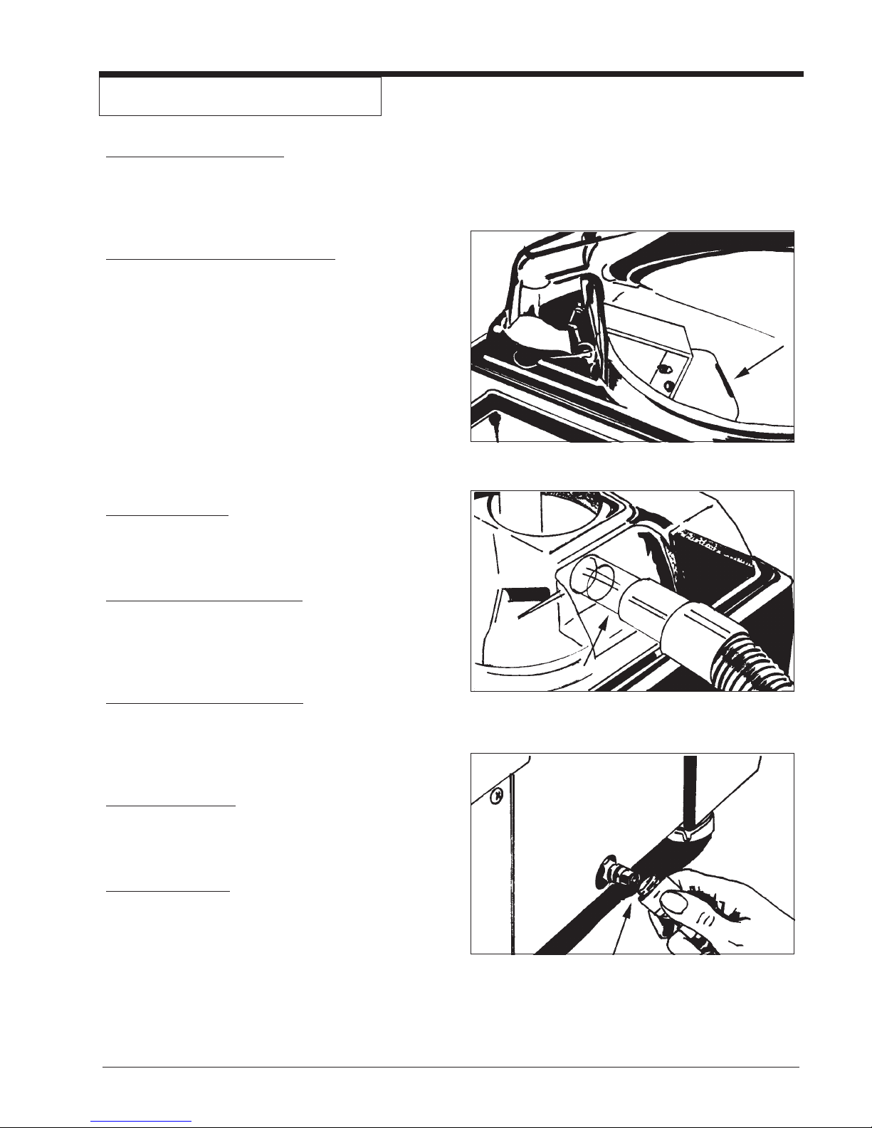
The Float Shut-Off See figure 1
Figure 1
The float shut-off is in the recovery tank. When the liquid
raises the float, the air stops moving through the machine.
The Vacuum Hose Connector See figure 2
The vacuum hose connector is on the dome assembly.
The Solution Hose Connector See figure 3
The solution hose connector is on the lower part of the
extractor, below the vacuum hose connector.
The Recovery Tank
The recovery tank is in the top of the machine. Make sure
the white pail is in the tank when the machine is running.
The Solution Tank
The solution tank is in the top of the machine next to the
recovery tank.
Figure 2
®
Clarke
Ext- 311 Owner's Manual Page 5
Figure 3
Page 7
HOW TO PREPARE THE MACHINE FOR OPERATION
To prepare the machine for operation, follow this procedure:
1. Connect the vacuum hose to the hose connector
on the extractor and to the end of the vacuum tube
on the floor tool.
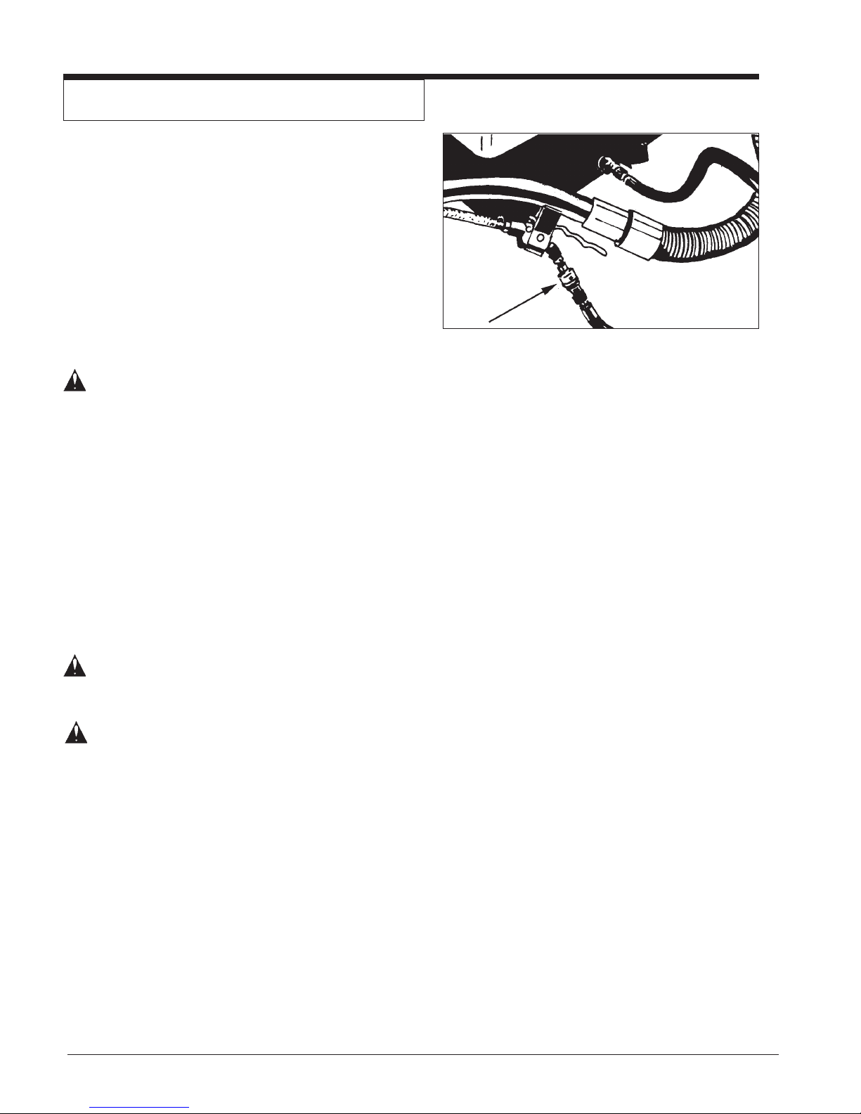
2. Connect the solution hose to the extractor and the
floor tool. To fasten the quick disconnect fitting,
slide the knurled collar on the female coupling away
from the opening. Push the male coupling into the
female coupling. See figure 4
WARNING: Do not use water that is hotter than
140°F (60°C).
3. Before moving the extractor onto the carpet, put
clean hot water into the solution tank.
Figure 4
4. Add a cleaning chemical, such as Clarkare
®
Extractor Concentrate, to the hot water. For the
correct amount, follow the directions shown on the
container.
5. If the extractor removes an excess amount of foam
from the carpet, add a de-foamer such as Clarkare
De-foamer Concentrate to the recovery tank. The
amount needed will vary according to the amount of
detergent already in the carpet.
CAUTION: To prevent damage, use a water-
based de-foamer rather than an oilbased de-foamer.
CAUTION: Do not leave the extractor or other
cleaning machines or tools on the
carpet when not in use. Cleaning
solution in the machines and tools
can leak onto the carpet and cause
light spots or stains.
NOTE: To order Clarkare® Extractor Concentrate, order
part no. 398421. To order Clarkare® Defoamer,
order part no. 398420.
®
For instructions for preparation and operation of your floor
tool or power brush tool, read the operator's manual given
with your floor tool or power brush tool.
Page 6 Clarke
®
Ext -311 Owner's Manual
Page 8
INSTRUCTIONS FOR CONNECTION TO THE
POWER SUPPLY AND ELECTRICAL GROUND - 120 V
CAUTION: This machine will operate only on an AC
frequency and on the specified electrical
voltage shown on the nameplate. Make
sure you have the correct frequency and
voltage before connecting the power
cord to an outlet.
This machine must be connected to an electrically ground
circuit in order to protect the operator from electric shock. This
machine has an approved power cord with three conductors as
well as a plug with three terminals. Connect the plug to a three
holed receptacle. For maximum protection against electric
shock, use a circuit that is protected by a ground fault circuit
interrupter.
This machine uses a 120 volt AC 50/60 cycle electrical circuit.
Make sure you have the correct frequency and voltage before
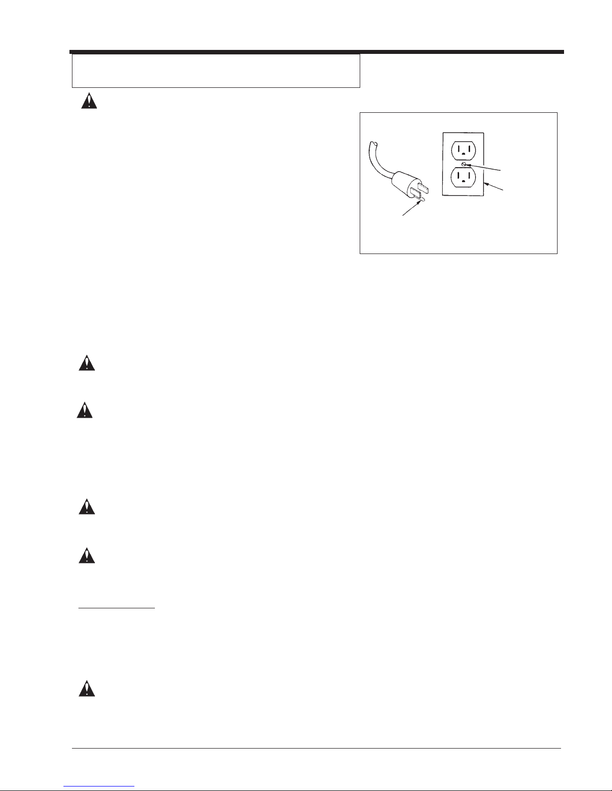
connecting the power cord to an outlet. The machine has a plug
as shown in Figure 5. If a receptacle connected to the electrical
ground as shown in Figure 5 is not available, contact an
electrical contractor. Do not us an adapter.
Ground Pin
Plate
Screw
Outlet must be
connected to
the electrical
ground
Figure 5
WARNING: To prevent possible electric shock, pro-
tect the machine from rain. Keep the
machine in a dry building.
WARNING: To prevent possible electric shock, al-
ways use a 3-wire electrical system connected to the electrical ground. For
maximum protection against electrical
shock, use a circuit that is protected by a
ground fault circuit interrupter. Consult
your electrical contractor.
WARNING: Do not cut, remove, or break the ground
pin. If the outlet does not fit the plug,
consult your electrical contractor.
WARNING: If the cords or plugs are worn or dam-
aged in any way, have them replaced by
an authorized service person.
Extension Cords
Use only an approved extension cord with three conductors, a
plug with three terminals and a three-holed connector body.
This machine has a power cord with a wire size of 16 AWG.
(AWG stands for American Wire Gauge).
CAUTION: If you use an extension cord, use one that
has a minimum wire size of 14 AWG. Be
sure your extension cord is no longer
than 50 ft. Do not join two extension
cords.
®
Clarke
Ext- 311 Owner's Manual Page 7
Page 9
INSTRUCTIONS FOR CONNECTION TO THE
POWER SUPPLY AND ELECTRICAL GROUND - 230 V
CAUTION: This machine will operate only on an AC
frequency and on the specified electrical
voltage shown on the nameplate. Make
sure you have the correct frequency and
voltage before connecting the power cord
to an outlet.
This machine must be connected to an electrical ground circuit
in order to protect the operator from electric shock. This
machine has an approved power cord with two main conductors
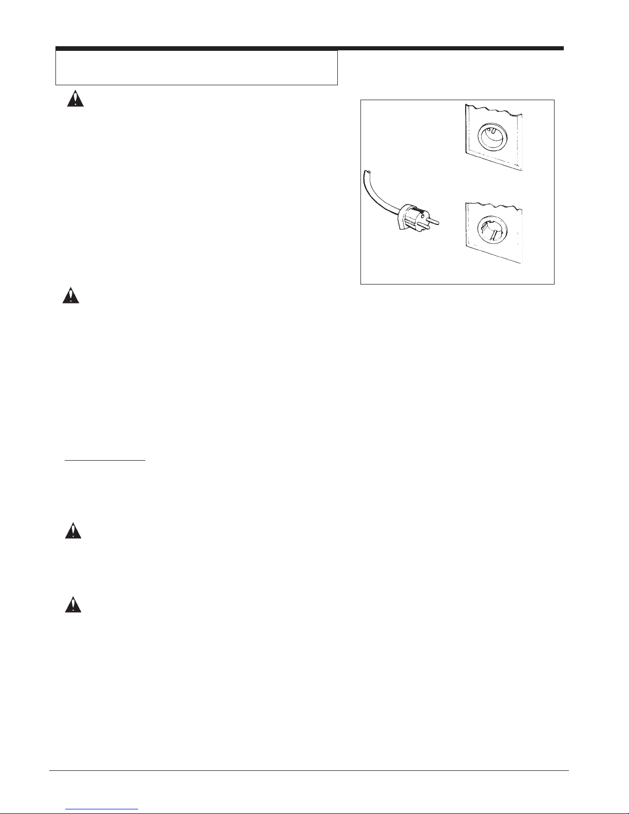
and one earthing conductor. Connect the plug to the type of
receptacle shown in figure 6. The green and yellow conductor
in the cord is the ground wire. Never connect this wire to any
terminal other than the ground terminal.
WARNING: Always use this machine with an AC
three-conductor electrical system connected to the electrical ground. Replace
any worn, cut or damaged cords. Replace any damaged plugs, receptacles, or
connector bodies. Do not move the
machine over an electrical cord. Always
lift the cord over the machine.
Extension Cords
Pin Earthing Contact
European Plug
Side Earthing Contact
Figure 6
Use only an approved extension cord with two main conductors,
and one earthing conductor. This machine has a power cord
with a wire size of 1.5mm2.
WARNING: If you use an extension cord, use one that
has a minimum wire size of 1.5mm2. Be
sure your extension cord is no longer
than 15 meters. Do not join two extension
cords.
WARNING: Do not cut, remove or break the ground
terminal. Do not try to fit a three-terminal
plug into a receptacle or connector body
that does not fit the plug. If the receptacle
or connector body does not fit the plug,
see your authorized Clarke Dealer to get
an authorized person to make the connection.
Page 8 Clarke
®
Ext -311 Owner's Manual
Page 10
MACHINE OPERATING INSTRUCTIONS
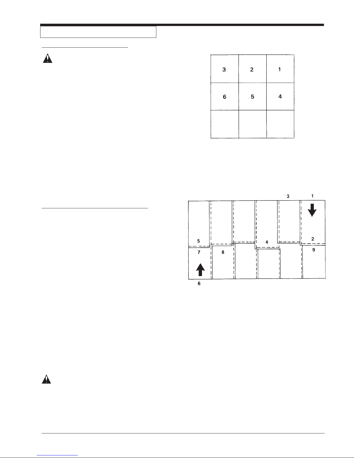
How to Clean an Area of Carpet See Figure 7
WARNING: Do not use water that is hotter
than 140°F (60°C).
To clean an area of carpet, follow this procedure:
1. Start the pump for the solution and the motor for the
vacuum on the extractor.
2. Begin at the right-hand corner of the carpet.
3. Hold the floor tool at the angle that gives the best
vacuum seal between the tool and the carpet.
4. Apply pressure to the lever for solution release. Pull
the tool toward you at a slow, steady speed. To
remove as much solution as possible, release the
lever before you stop moving backward.
5. To clean the edge of a room, move the tool along the
baseboard until the edge of all the carpet is cleaned.
6. To clean a small area of carpet, clean the carpet in
sections three feet square. As you make more
passes, repeat one inch of the area already cleaned.
7. To remove more liquid from the carpet, make passes
over the area already cleaned, but do not apply
pressure to the lever for the solution.
Figure 7
How To Clean A Larger Area Of Carpet See Fig. 8
To clean a larger area of carpet, follow this procedure:
1. Begin at the right-hand corner of the carpet.
2. Make a pass halfway along the edge of the carpet.
Pull the tool backward at a steady speed.
3. Move to the edge of the carpet. Make another pass
next to your first pass.
4. As you make more passes, repeat one inch of the
area already cleaned. If you use a power brush tool,
repeat one inch of the area already cleaned by the
brush. Make each pass four inches different in length
to prevent making a line in the center of the carpet.
5. Make more passes until half of the carpet is cleaned.
To remove more liquid from the carpet, make passes
over the area already cleaned, but do not apply
pressure to the lever for the solution.
6. Move to the right-hand corner of the part of the carpet
not yet cleaned.
7. Make a pass halfway along the edge of the carpet.
8. As you make passes, repeat one inch of the area
already cleaned.
9. Make more passes until all of the room is cleaned.
Figure 8
CAUTION: Clarke will not be held liable for
damage to the carpet, or poor results because of the operator's lack
of ability.
®
Clarke
Ext- 311 Owner's Manual Page 9
Page 11
MAINTENANCE
WARNING: Maintenance and repairs must
be done by authorized personnel only. Keep all fasteners tight.
Use only genuine Clarke parts.
WARNING: Do not operate this machine un-
less it is completely assembled.
NOTE: For maintenance of the floor tools or power
brush tools, read the manual given with the tools.
After Each Use of the Machine
1. To remove unused cleaning solution from the
solution tank, put the end of the vacuum hose in
the solution tank. Start the vacuum motor. Stop
the motor when the tank is empty.
2. To prevent damage to the valves and jets, flush
one gallon of clean water through the solution
system and the tools.
3. Disconnect the power cord from the outlet.
4. Remove the recovery tank cover.
5. Lift the pail and discard the solution.
6. Rinse the pail with clean water.
7. Use a dry cloth to wipe the tools and both tanks,
inside and out.
8. Apply a small amount of silicone lubricant to the
quick-disconnect fittings. To prevent damage to
the O-rings, do not use an oil lubricant.
9. Clean and inspect the gasket on the vacuum
shut-off valve. If the gasket is damaged, replace
the gasket.
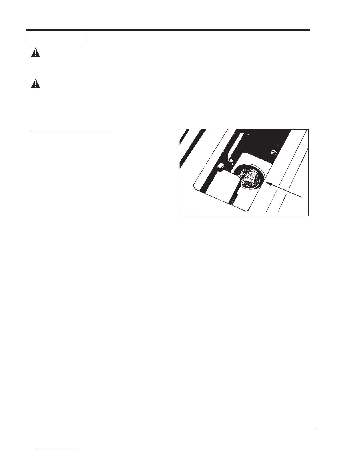
10. Inspect and clean the filter screen in the bottom
of the solution tank. See figure 9. To remove the
filter screen, turn the filter counterclockwise. To
Figure 9
Page 10 Clarke
®
Ext -311 Owner's Manual
Page 12
MAINTENANCE (CONT)
How To Prevent Damage From Freezing Temperatures
To prevent damage from freezing temperatures follow this
procedure:
1. Use the vacuum hose to remove all the solution from
the clean solution tank.
2. Connect the solution hose to the extractor and a floor
tool.
3. Put approximately 1 quart of antifreeze solution in the
solution tank.
4. Put the switch for the pump in the "I" position.
5. Put the end of the floor tool in the recovery pail.
6. Press the lever on the floor tool to activate the pump.
7. Make sure the solution runs through the system.
8. Release the lever on the floor tool to stop the pump.
9. Flush the antifreeze solution from the system before
using the extractor.
WARNING: Electrical repairs must be done by
authorized personnel only.
WARNING: After electrical repairs are done to the
machine, the machine must be tested
for electrical safety.
How To Get Access To The Pump and Vacuum Motor
To get access to the pump and the vacuum motor, follow
this procedure:
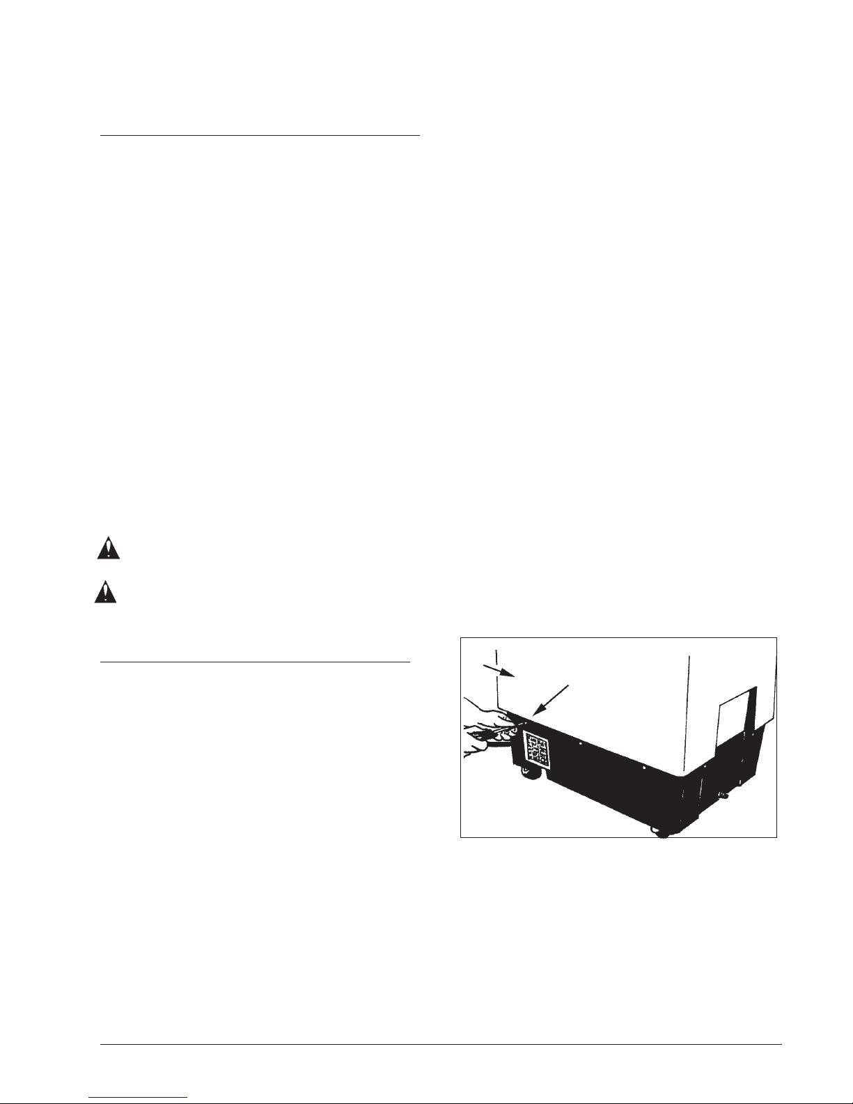
1. Remove the dome.
2. Empty both tanks.
3. Remove the pail.
4. Remove the ten screws from the lower housing (1).
5. Lift the upper housing from the machine (2).
See figure 10.
2
1
Figure 10
®
Clarke
Ext- 311 Owner's Manual Page 11
Page 13
Maintenance Of The Motor
This machine has a vacuum motor that uses carbon
brushes. The carbon brushes in the motor must be
checked every three months, or every 500 hours of operation, whichever comes first. If either of the brushes is
shorter than 3/8 inch, replace both of the carbon brushes.
How To Check The Commutator And The Carbon
Brushes
WARNING: Electrical inspections must be made
by a person authorized to make
electrical repairs.
To check the commutator and the carbon brushes follow
this procedure:
1. Disconnect the power cord from the electrical outlet.
2. Remove the dome.
3. Empty both tanks.
4. Remove the pail.
5. Remove the ten screws from the lower housing.
6. Lift the upper housing from the lower housing.
7. Put the machine on its side.
8. Disconnect the ground wire.
9. Remove the two screws from the bottom of the
machine that hold the motor bracket.
10. Remove the plastic motor cover.
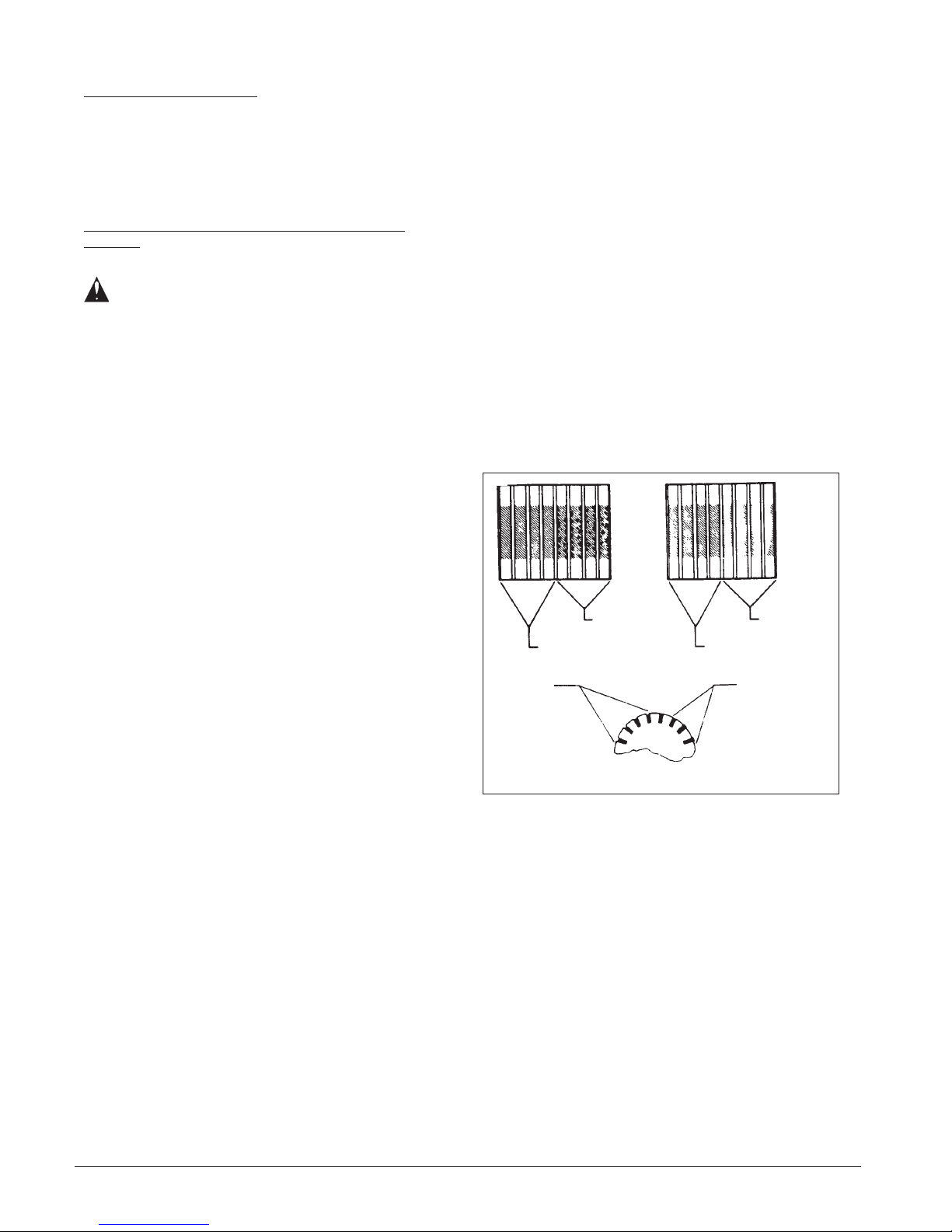
11. Inspect the commutator. See figure 11. Take the
machine to a Clarke authorized repair location if you
see any of the following conditions:
a. Small holes in the surface of the commutator.
See "A" in figure 11.
b. Uneven color. Look for an even dark brown color.
Clean areas or very dark areas indicate a problem.
See "B" in figure 11.
c. High mica. The mica insulation must be lower than
the commutator bars. See "C" in figure 11.
GOOD
UNEVEN
GOOD
SMALL
HOLES
GOOD
AB
HIGH MICA
12. To check the carbon brush assemblies, remove the
two screws from the holding bracket.
13. Remove the brackets.
14. Remove the carbon brush assemblies.
15. Check the carbon brush assembly. Replace both
carbon brush assemblies if either carbon brush is
shorter than 3/8 inch. If either brush is shorter than ½
inch, order replacement brushes. Be ready to replace
both carbon brushes earlier than the normal inspection
time.
16. Put the motor brushes in position.
17. Using the two screws, install the bracket that holds the
carbon brushes.
18. Install the plastic motor cover.
19. Connect the ground wire.
20. Install the motor holding bracket.
21. Install the lower housing to the upper housing.
Page 12 Clarke
C
Figure 11
®
Ext -311 Owner's Manual
Page 14
HOW TO CORRECT PROBLEMS IN THE MACHINE
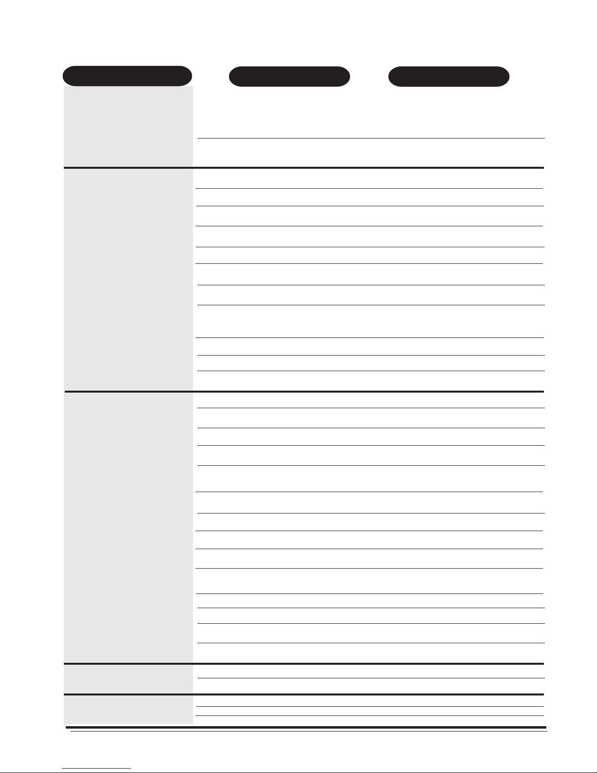
Problem
The machine will not run.
There is no suction.
1. The machine has no power.
2. The power cord is damaged.
1. The vac motor does not run.
2. The vac motor switch is defective.
3. There is a loose motor connection.
4. There is an obstruction in the vacuum
hose.
5. The recovery tank is full.
6. The dome gasket is worn or damaged.
7. The dome is not in the correct position.
8. The internal vac hose is damaged
or stopped.
9. The dome is damaged.
ActionCause
1. Make sure the machine is connected to the
correct frequency and voltage, and all connections are tight.
Make sure the plug is in the electrical outlet.
2. Contact an authorized service person to replace
the cord.
1. Put the switch for the vacuum in the "I" position.
2. Contact an authorized service person.
3. Contact an authorized service person.
4. Remove the obstruction.
5. Remove the liquid from the tank.
6. Contact an authorized service person to replace
gasket.
7. Put the dome in the correct position.
8. Contact an authorized service person.
9. Replace the dome.
There is no pressure.
10.The motor brushes are worn.
11.A wrong size pail is being used.
1. The switch is in the "OFF" position.
2. The pressure switch is damaged.
3. The pump motor will not run.
4. The pump motor brushes are worn.
5. The quick disconnect fitting is dirty
or stopped.
6. The solution hose is bent.
7. The pump is worn.
8. The pump switch is defective.
9. The pump connections are loose.
10.The pump intake and oulet valves are
worn.
11.The thermo protector is open.
12.The solution tank is empty.
13.The intake screen is dirty.
10.Replace the motor brushes.
11.Use only the pail given with the machine.
1. Put the switch in the "I" position.
2. Contact an authorized service person.
3. Contact an authorized service person.
4. Contact an authorized service person.
5. Contact an authorized service person.
6. Straighten the hose. Replace if damaged.
7. Contact an authorized service person.
8. Contact an authorized service person.
9. Contact an authorized service person.
10.Contact an authorized service person.
11.Contact an authorized service person.
12.Fill the solution tank.
13.Clean the screen.
14.The rectifier in the pump motor is bad.
The solution tank leaks.
The recovery tank overflows.
®
Clarke
Ext- 311 Owner's Manual Page 13
1. The intake gasket is worn.
2. The tank is damaged.
1. The float is dirty or damaged.
2. There is too much foam.
3. The float gasket is dirty or damaged.
14.Contact an authorized service person.
1. Contact an authorized service person.
2. Contact an authorized service person.
1. Clean the float. Replace if damaged.
2. Put defoamer in the solution. Order P/N 398420.
3. Clean the gasket. Replace if damaged.
Page 15

Clarke
®
EXT-311
Machine Variables and Accessories 1/00
Variable
Code
04090A Breakdown: 04090A EXT 311 Base 120V
04091A Breakdown: 04090A EXT 311 Base 120V
59230A 8" Plastic Wand Floor Tool
04092A Breakdown: 04090A EXT 311 Base 120V
59229A 12" Metal Floor Tool
04093A Breakdown: 04090A EXT 311 Base 120V
04016A PB-12 Power Brush 120V
04095A Breakdown: 04095A EXT 311 Base 230V
04096A Breakdown: 04095A EXT-311 Base 230V
59230A 8" Plastic Wand Floor Tool
04097A Breakdown: 04095A EXT-311 Base 230V
59229A 12" Metal Floor Tool
04098A Breakdown: 04095A EXT-311 Base 230V
04017A PB-12 Power Brush 230V
ACCESSORIES
Descriptions Part No.
Clarkare® Concentrate - case (4-1 gal.) 398425
Defoamer - case (4-1 gal.) 398426
Traffic Lane Spotter - case (4-1 gal.) 398427
Upkeep Shampoo - case (4-1 gal.) 398430
Carpet Dryer Standard 04128A
Carpet Dryer Deluxe 04130A
4" Metal Hand Tool 59228A
4" Plastic Hand Tool 59231A
4" Hand Tool & Hose Assembly 55173A
8" Plastic Wand Floor Tool 59230A
12" Metal Floor Tool 59229A
PB - 12 Power Brush 12" 04016B
10' Vac-Solution Hose Assembly 59232A
20' Vac-Solution Hose Assembly 55183A
1½ to 1½" Coupler 682408
Page 14 Clarke
®
Ext -311 Owner's Manual
Page 16
Division of
EXT 311
Extractor
Section II
Parts and Service Manual
®
Clarke
Ext- 311 Owner's Manual Page 15
(70471A)
Page 17
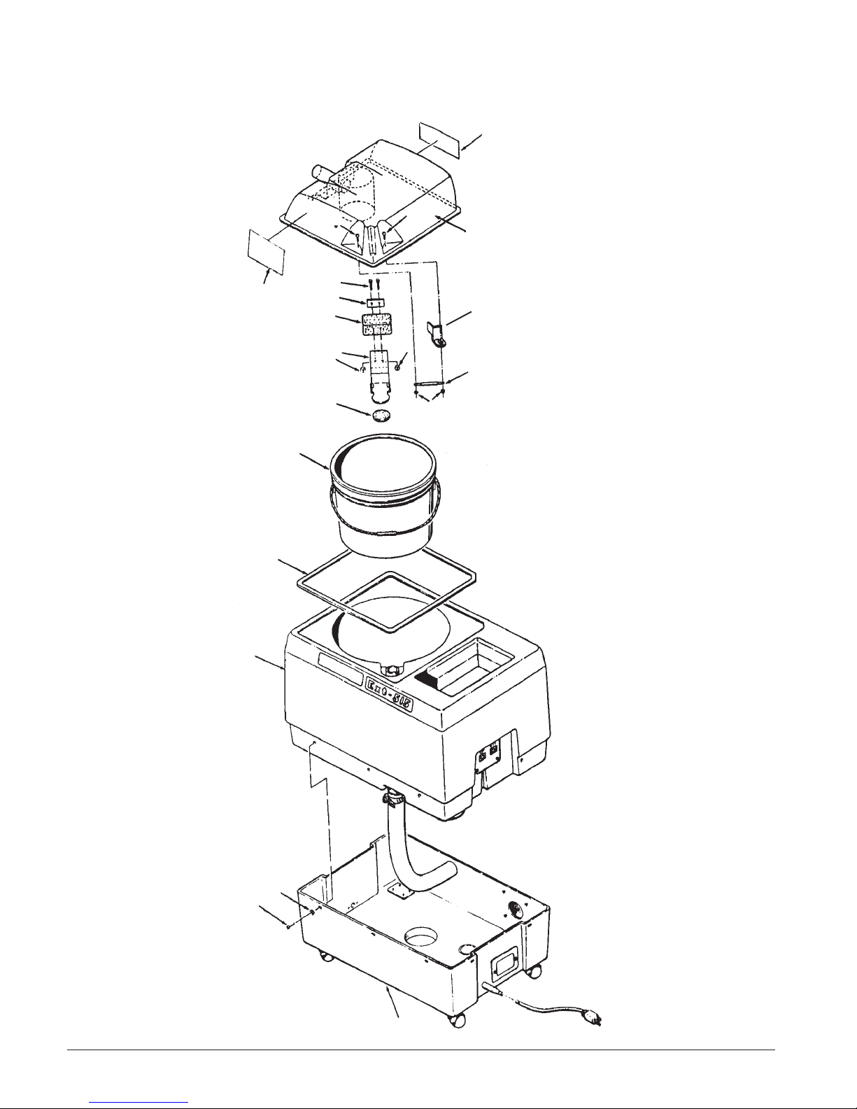
Clarke® EXT-311
Assembly Drawing 2/99
3
2
14
13
12
10
5
5
4
6
7
8
9
12
20
11
12
15
16
17
1
Page 16 Clarke
®
Ext -311 Owner's Manual
Page 18

Clarke® EXT-311
Assembly Drawing Parts List 2/99
Item # Description
Part No.
1 Pgs 16/17 Assembly, Base 1
2 73289B Label, Warning 1
3 73290A Label, Instruction 1
4 32504C Dome, Recovery 1
5 962027 Screw, #8-32 x ½ Pan 2
6 85350A Screw, #8-32 x 2½ Pan 2
7 62401A Clamp, Float 1
8 33801A Float 1
9 61110B Bracket, Float 1
10 34213A Gasket, Float Shut-off 1
11 67104A Rod, Float Pivet 1
12 81109A Nut, #8-32 ESNA S.S. 4
13 36901A Pail, Recovery 1
14 34235B Gasket, Dome Assembly 1
15 Page 18 Asm. Solution Tank 1
16 980982 Washer #10 10
17 85500A Screw #10-32½ 10
18 Page 16 Hose from Vac Motor Ref.
19 Page 16 Clamp, Hose Ref
20 69431A Bracket, Tank 1
Ref. 13001C Dome & Label Assembly 1
(Includes Items 2,3,4)
NI 699203 Tag, Caution 1
Qty.
®
Clarke
Ext- 311 Owner's Manual Page 17
Page 19
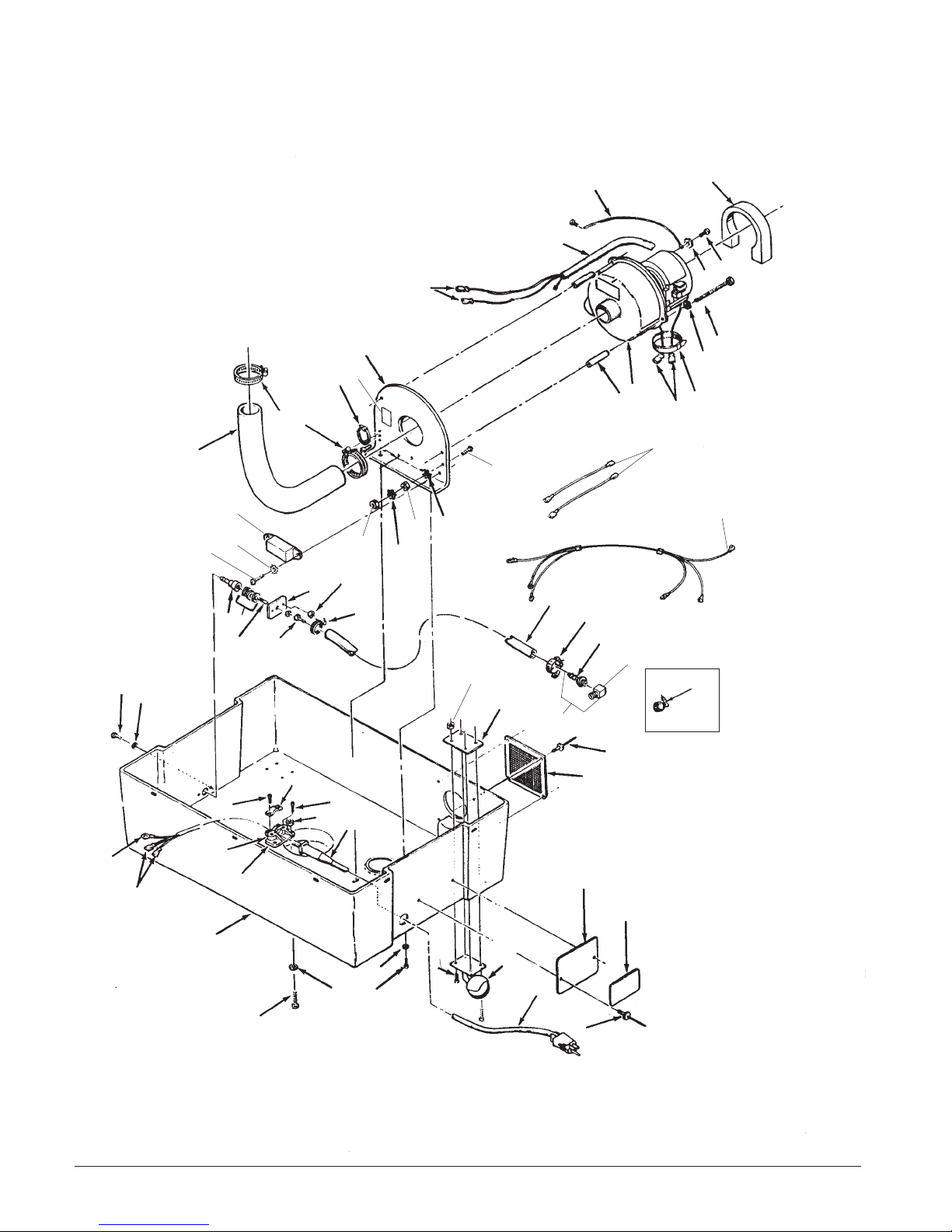
Clarke® EXT-311
Base Assembly Drawing 11/02
28
39
7
9
8
10
5
4
11
26
3
54
6
2
1
13
16
52
49
6
47
51
41
50
11
40
33
38
15
27
14
17
11
14
11
43
17
55
53
56
57
18
19
230V only
115V only
20
21
37
34
27
32
31
36
42
5
35
22
23
30
29
39
26
28
Page 18 Clarke
46
25
24
20
®
Ext -311 Owner's Manual
Page 20

Clarke
®
EXT-311
Base Assembly Drawing Parts List 11/02
Item # Description
Part No. Item # Description
Qty.
1 35131A Hose, Vac to Tank 1
2 752020 Clamp, Hose 2
3 980646 Washer 3
4 65903A Mount, Vac Motor 1
5 47711A Terminal, ¼ FIFQDC 2
6 699202 Tie, Nylon 2
7 954010 Wire, Assembly Green 1
8 49739A Harness, Control Ref.
9 34234A Gasket, Intake Air 1
10 962546 Screw, 10-24 x ½ 1
11 980603 Washer #10 SH 3
13 58534A Spacer 3
14 920234 Nut 2
15 66617A Plate, Q.D. Mounting 1
16 44923A Motor, Vac 120V 1
44924A Motor, Vac 230V 1
17 50248A Clamp, Hose 2
18 692870 Elbow, (115V) 1
19 66633A Plate, Nut 4
20 930074 Rivet, 1/8 Dia. Closed 6
21 603801 Grill, Housing 1
22 66634A Plate, Label Mounting 1
23 Label, Serial No. 1
24 42214A Cord, 120V 35' 1
42231A Cord, 230V 10m 1
25 52100A Caster, 2" Ball 4
26 962950 Screw 3
27 920200 Nut, 10-24 Hex (115V only) 4
920200 Nut, 10-24 Hex (230V only) 5
Part No.
28 962109 Screw, 10-24 x 5/8 115V 4
962109 Screw, 10-24 x
29 980646 Washer ¼ Plain 5
30 30321A Base (Rotomold) 1
31 38002A Strain Relief 1
32 964003 Screw, 5.0 x .8 x 20 PN*ST 2
33 980645 Washer, 13/32 I.D. x 13/16 O.D. 3
34 672012 Clamp, Cord 1
35 670811 Bracket, Strain Relief 1
36 672011 Clamp, Strain Relief 1
37 964005 Screw 5.0 x 0.8 x 16 PN*ST 2
38 50300A Adapter, 1/8 NPT to 3/8 Hose 1
39 980982 Washer, #10 Plain Flat 4
40 725729 Nipple
41 737140 Quick Disconnect 1
42 170687 Terminal, #10 Ring 1
43 35147A Hose, 3/8 x 14" 1
46 962823 Screw, (115V only) 12
962983 Screw, (230V only) 6
47 962113 Screw 10-32 x 1 1
49 47712A Terminal, ¼ FIFQD 2
50 47201A Filter (CE only) 1
51 962333 Screw (CE only) 6
52 49310A Lead Assembly (CE only) 2
53 49642B Harness, Grounding (CE only) 1
54 77094A Label, Ground Symbol
55 170028 Hosebarb (230V only) 2
56 170039 Elbow (230V only) 2
5
/8 230V 5
1
/8 Close Pipe 1
(CE only)
Qty.
1
®
Clarke
Ext- 311 Owner's Manual Page 19
Page 21
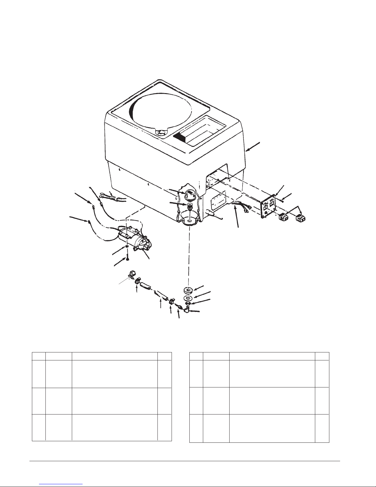
Clarke® EXT- 311
Solution Tank Assembly Drawing & Parts List 11/02
3
15
21
18
1
2
17
13
14
(115V only)
Item # Description
Part No. Item # Description
1 728535 Strainer 1
2 60306A Adapter, Filter 1
3 30319A Tank 1
4 833401 Gasket, Drain 1
5 980630 Washer, 3/4 " Plain 1
6 920264 Nut, 3/4 -16 1
7 170040 Elbow, St. ¼ NPT 1
8 170030 Hosebarb, 3/8" x ¼" NPT 1
9 50248A Clamp, Hose 2
10 35147A Hose, 3/8" x 14" 1
11 692870 Elbow (115V) 1
NI 170039 Elbow (230V) See pg 16 1
11
12
4
5
9
10
9
8
Qty.
12 45928A Pump 120V 1
13 980982 Washer, #10 4
14 962113 Screw, 10-32 x 1 4
15 47711A Terminal, ¼ FIFQD (115V ) 1
16 47316B Switch, Rocker DPST 2
17 912064 Terminal, Clip #10 1
18 49739A Harness Control 1
19 37303A Switch, Plate 1
20 962929 Screw, 10-32 x 3/8 4
21 47905A Terminal, ¼ FIMQD (230V) 1
NI 699202 Tie, Cable 1
6
7
Part No.
697011 Pump 230V 1
19
20
16
18
Qty.
Page 20 Clarke
®
Ext -311 Owner's Manual
Page 22
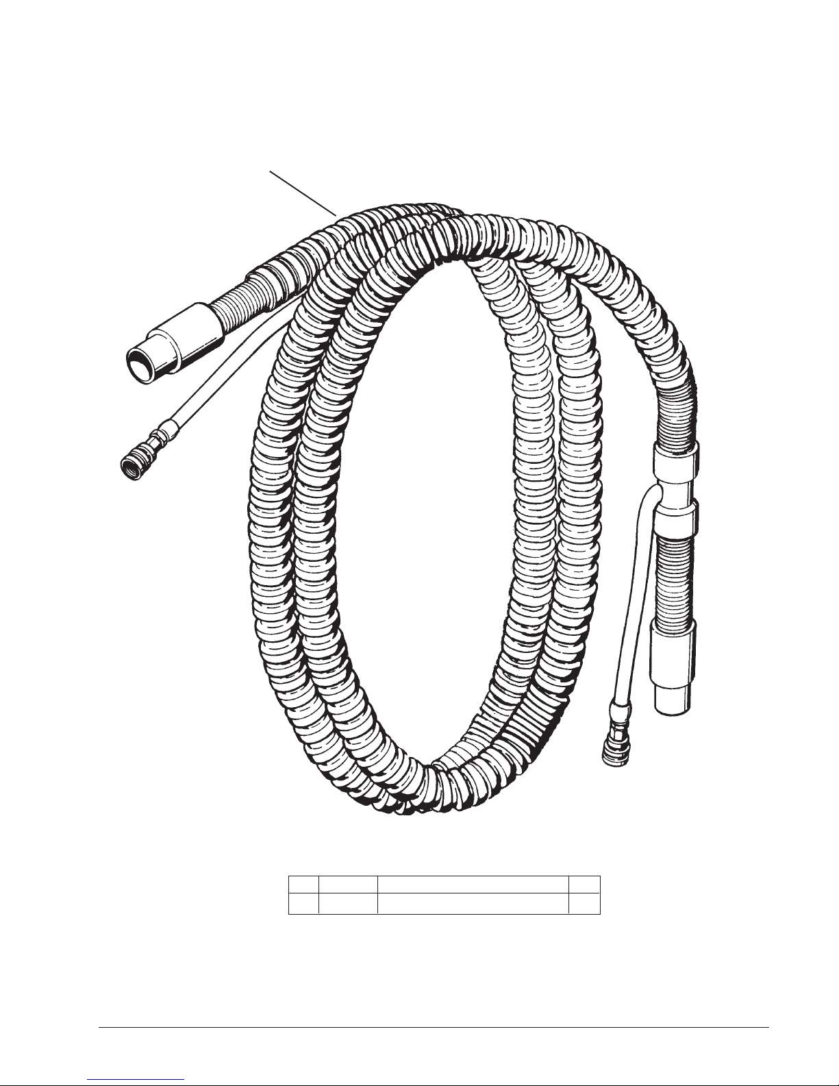
Clarke® EXT- 311
10 Ft. Hose Assembly Drawing
Part #59232A 11/98
1
®
Clarke
Ext- 311 Owner's Manual Page 21
Item # Description
Part No.
1 59232A Hose, Pumper 1.5" I.D. x 10'L 1
Qty.
Page 23
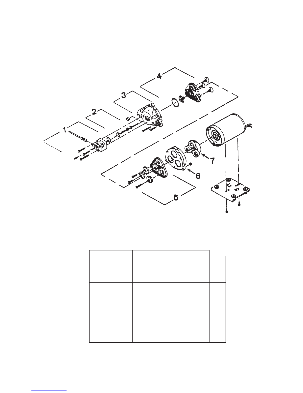
Clarke® EXT- 311
Pump (#45928A) 100 PSI/120V
Drawing and Parts List - 11/98
Ref # Part No. Description Qty
1 55379A Kit, Switch - Viton 60 psi 1 x
2 55374A Kit, Dual Check Valves 1 x x
3 54715A Housing, Upper 1 x
4 55373A Kit, Vavle 1 x
5 53201A Kit, Diaphragm 1 x
6 54888A Housing, Lower 1 x
7 54837A Kit, Drive Assembly 1 x
Page 22 Clarke
45909B
53057A Kit, Switch - Viton 80/100 psi 1 x
53056A Kit, Switch 80/100 psi 1 x
52908A Kit, Check Valves 1 x
54881A Housing, Upper 1 x x
59783A Kit, Valve 1 x x
53205A Kit, Diaphragm 1 x x
54882A Housing, Lower 1 x x
52909A Kit, Drive Assembly 1 x
52907A Kit, Drive Assembly 1 x
®
45928A
45929A
Ext -311 Owner's Manual
Page 24

NOTES
®
Clarke
Ext- 311 Owner's Manual Page 23
Page 25
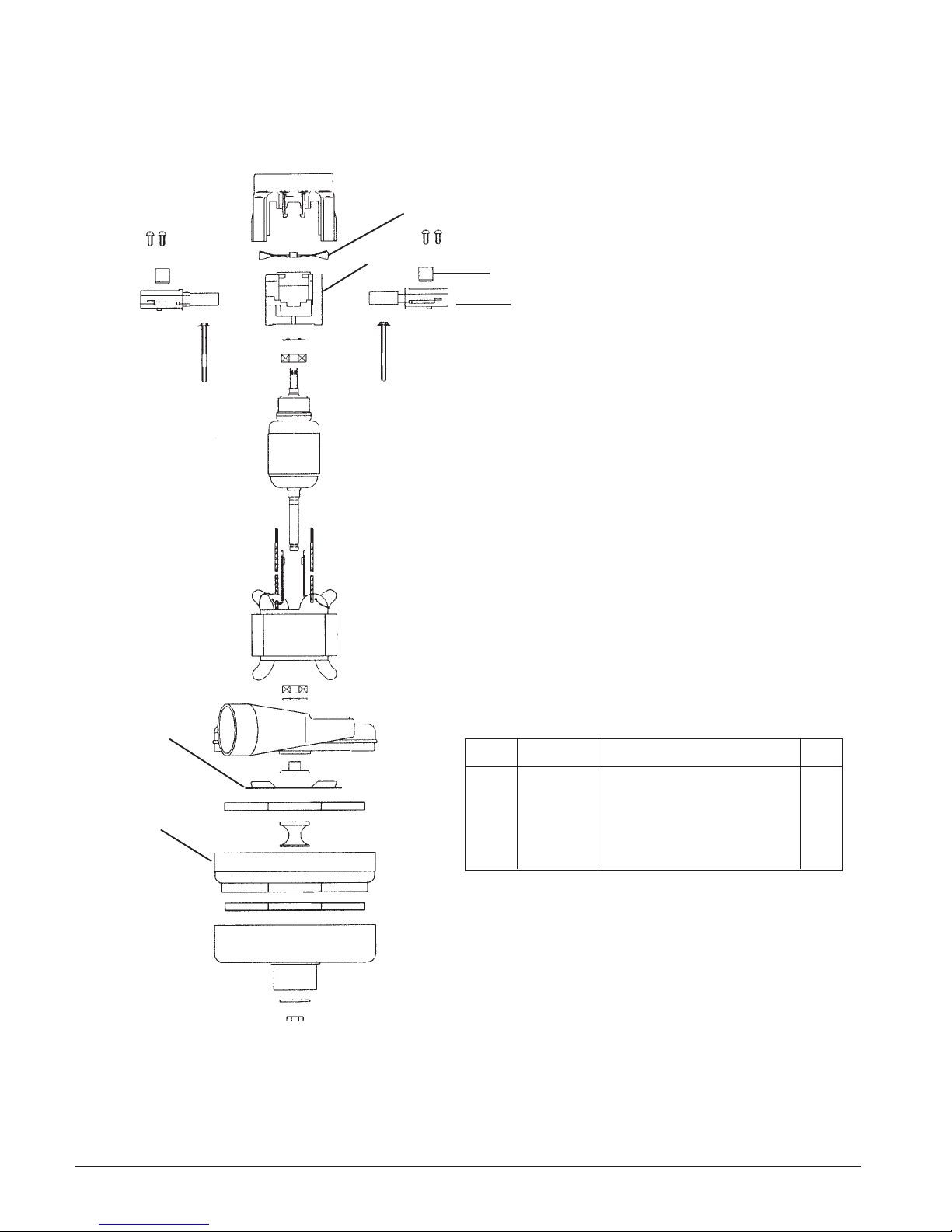
Clarke
®
EXT- 311
Motor 230V #44924A - 11/98
1
2
3
4
5
Ref # Part No. Description Qty
1 53905A Fan 1
2 50618A Comm End Bracket 1
3 51914A Clamp 2
6
Page 24 Clarke
4 40813A Brush Mechanism 2
5 53995A Air Seal Fan 1
6 53908A Stationary Fan 1
®
Ext -311 Owner's Manual
Page 26
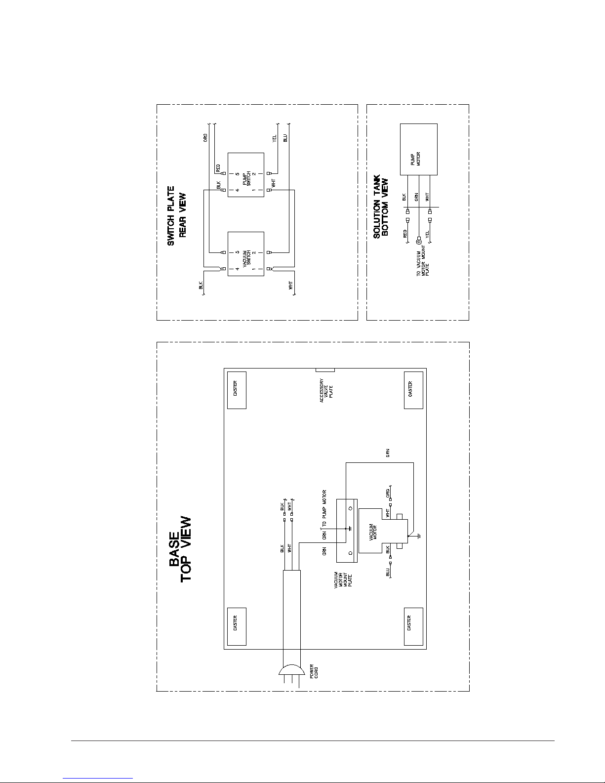
Clarke® EXT- 311
Connection Diagram 120V - 9/95
®
Clarke
Ext- 311 Owner's Manual Page 25
Page 27
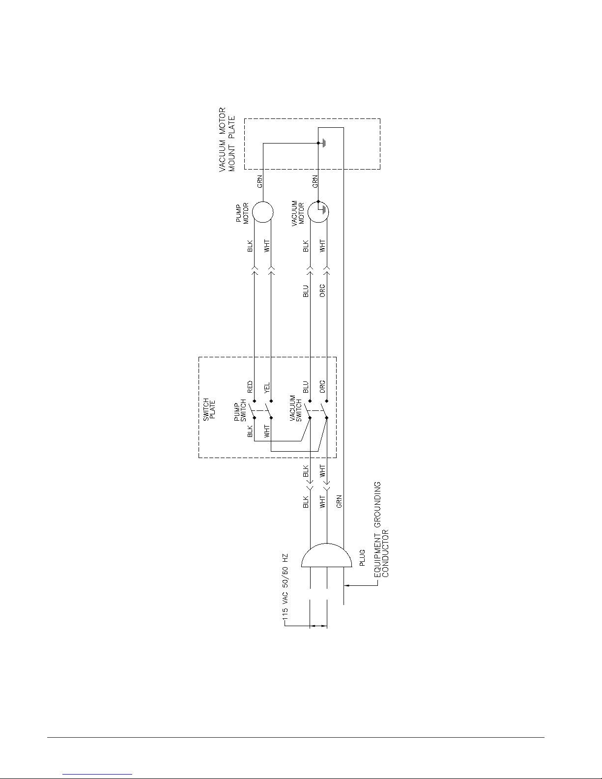
Clarke® EXT- 311
Wiring Diagram 120V - 9/95
Page 26 Clarke
®
Ext -311 Owner's Manual
Page 28
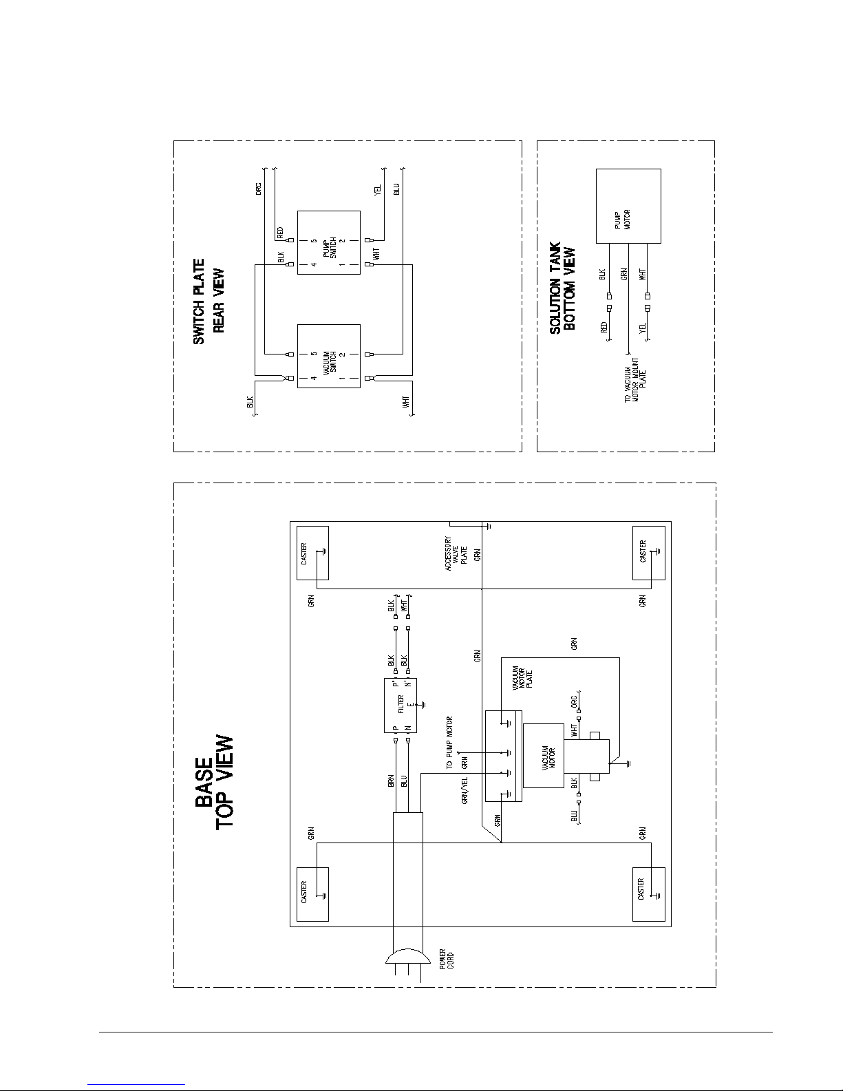
Clarke® EXT- 311
Connection Diagram 230V - 9/98
®
Clarke
Ext- 311 Owner's Manual Page 27
Page 29
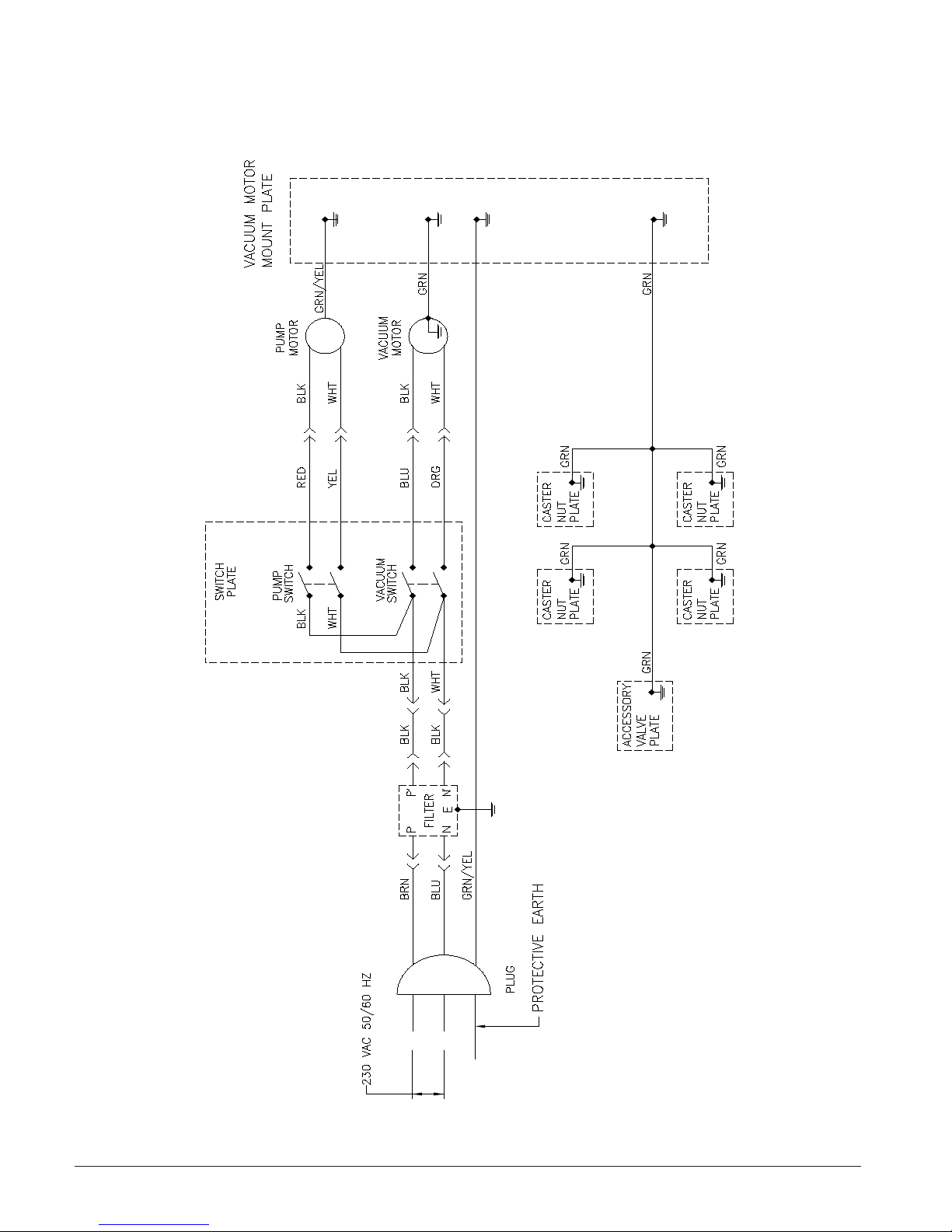
Clarke® EXT- 311
Wiring Diagram 230V - 9/98
Page 28 Clarke
®
Ext -311 Owner's Manual
Page 30

PRODUCT SUPPORT BRANCHES
U. S. A. Locations European Locations
HEAD OFFICE
ALTO U.S. Inc., St. Louis, Missouri
16253 Swingley Ridge Road, Suite 200
Chesterfield, Missouri 63017-1725
PRODUCTION F A CILITIES
Clarke®, Springdale, Arkansas
2100 Highway 265
Springdale, Arkansas 72764
(479) 750-1000
Customer Service - 1-800-253-0367
Technical Service - 1-800-356-7274
American Lincoln®, Bowling Green, Ohio 43402
1100 Haskins Road
SERVICE FACILITIES
Clarke® , Carlstadt, New Jersey 07072
150 Commerce Road
(201) 460-4774
Clarke®, Elk Grove, Illinois 60007
2280 Elmhurst Road
(847) 956-7900
Clarke®, Denver, Colorado 80204
1955 West 13th Ave.
(303) 623-4367
PRODUCTION F A CILITIES
ALTO Danmark A/S, Aalborg
Blytaekkervej 2
DK-9000 Aalborg
+45 72 18 21 00
ALTO Danmark A/S, Hadsund
Industrikvarteret
DK-9560 Hadsund
+45 72 18 21 00
SALES SUBSIDIARIES
Clarke® Canada Ltd., Rexdale Ontario
24 Constellation Ct.
(416) 675-5830
ALTO Overseas Inc., Sydney (Australia)
1B/8 Resolution Drive
Caringbah NSW 2229
+61 2 9524 6122
ALTO Cleaning Systems Asia Pte Ltd., Singapore
No. 17 Link Road
Singapore 619034
+65 268 1006
ALTO Deutschland GmbH, Bellenberg (Germany)
Guido-Oberdorfer-Straße 2-8
89287 Bellenberg
+49 0180 5 37 37 37
Clarke®, Houston, Texas 77040
7215 North Gessner Road
SALES AND SERVICE FACILITIES
American Lincoln® / Clarke®, Madison Heights,
Michigan 48071-0158
29815 John R.
(810) 544-6300
American Lincoln® / Clarke®, Marietta, Georgia 30062
1355 West Oak Common Lane
(770) 973-5225
®
Clarke
Clarke American Sanders
A.L. Cook
Customer Service Headquarters and Factory
2100 Highway 265
Springdale, Arkansas 72764
(479) 750-1000
Technical Service
1-800-356-7274
ALTO Cleaning Systems (UK) Ltd., Penrith
Gilwilly Industrial Estate
Penrith
Cumbria CA11 9BN
+44 1768 868 995
ALTO France S.A. Strasbourg
B.P. 44, 4 Place d’Ostwald
F-67036 Strasbourg
Cedex 2
+33 3 8828 8400
ALTO Nederland B.V. Vianen
Stuartweg 4C
NL-4131 NJ Vianen
+31 347 324000
ALTO Sverige AB, Molndal (Sweden)
Aminogatan 18
Box 4029
S-431 04 Molndal
+46 31 706 73 00
ALTO Norge A/S, Oslo (Norway)
Bjornerudveien 24
N-1266
+47 2275 1770
®
Clarke
Ext- 311 Owner's Manual Page 29
Page 31
Clarke
This Clarke Industrial/Commercial Product is warranted to be free from defects in materials and workmanship under
normal use and service for a period of one year from the date of purchase, when operated and maintained in accordance
with Clarke's Maintenance and Operations instructions.
This warranty is extended only to the original purchaser for use of the product. It does not cover normal wear parts such as
electrical cable, rubber parts, hoses and motor brushes.
If a difficulty develops with the product you should:
a) Contact the nearest authorized Clarke repair location or contact Clarke U.S. Inc. Service Operations Department, 2100
Highway 265, Springdale, Arkansas 72764, for the nearest authorized Clarke repair location. Only these locations are
authorized to make repairs to the product under this warranty.
b) Return the product to the nearest Clarke repair location. Transportation charges to and from the repair location must be
prepaid by the purchaser.
c) Clarke will repair the product and/or replace any defective parts without charge within a reasonable time after receipt of
the product.
Clarke's liability under this warranty is limited to repair of the product and/or replacement of parts and is given to
purchaser in lieu of all other remedies, including INCIDENTAL AND CONSEQUENTIAL DAMAGES.
THERE ARE NO EXPRESS WARRANTIES OTHER THAN THOSE SPECIFIED HEREIN. THERE ARE NO WARRANTIES
WHICH EXTEND BEYOND THE DESCRIPTION OF THE FACE HEREOF. NO WARRANTIES, INCLUDING BUT NOT LIMITED
TO WARRANTY OF MERCHANTABILITY, SHALL BE IMPLIED. A warranty registration card is provided with your Clarke
product. Return the card to assist Clarke in providing the performance you expect from your new floor machine.
®
Clarke
, 2100 Highway 265, Springdale, Arkansas 72764.
®
LIMITED U.S. WARRANTY
Clarke
®
reserves the right to make changes or improvements to its machine without notice.
Always use genuine Clarke
®
Parts for repair.
Division of
2100 Highway 265
Springdale, Arkansas, 72764
Page 32
E
EXT 515
Extractor
READ THIS BOOK
This book has important information for the use and safe operation of this machine. Failure to read this
book prior to operating or attempting any service or maintenance procedure to your Clarke machine could
result in injury to you or to other personnel; damage to the machine or to other property could occur as
well. You must have training in the operation of this machine before using it. If your operator(s) cannot
read English, have this manual explained fully before attempting to operate this machine.
Si Ud. o sus operadores no pueden leer el Inglés, se hagan explicar este manual completamente antes
de tratar el manejo o servicio de esta máquina.
All directions given in this book are as seen from the operator’s position at the rear of the machine.
For new books write to: ALTO U.S. Inc., 2100 Highway 265, Springdale, Arkansas 72764.
Form No. 78165A 9/98 CLARKE TECHNOLOGY Printed in the U.S.A.
Page 33

CONTENTS OF THIS BOOK
Operator Safety Instructions ................................................................................. 3
Introduction and Machine Specifications ................................................................4
Controls and Machine Features ..............................................................................5
How to Prepare the Machine for Operation .............................................................6
Instructions for Connection to the Power Supply - 115V
Extension Cords - 120V .............................................................................7
Instructions for Connection to the Power Supply - 230V
Extension Cords - 230V ..........................................................................................8
Machine Operating Instructions...............................................................................9
How to Clean an Area of Carpet.................................................................9
How To clean a Larger Area of Carpet.......................................................9
Maintenance ...........................................................................................................10
After Each Use of the Machine ..................................................................10
How to Prevent Damage from Freezing Temperatures ...............................11
The Pump and Vacuum Motor...................................................................11
How To Check The Commutator and The Carbon Brushes.........................12
How to Correct Problems in the Machine ................................................................13
Assembly Drawing #1 .............................................................................................16
Parts List.................................................................................................17
Assembly Drawing #2 and Parts List .......................................................................18
Hose Assembly Drawing & Parts List ......................................................................19
Pump Drawing & Parts List .....................................................................................20
Motor Drawing & Parts List 120V ............................................................................21
Motor Drawing & Parts List 230V ............................................................................22
Wiring Diagrams.....................................................................................................23
Page 2
CLARKE TECHNOLOGY EXT 515 Operator's Manual
Page 34
OPERATOR SAFETY INSTRUCTIONS
WARNING AVERTISSEMENT ADVERTENCIA
For the safe operation of this machine, read and understand all warnings and cautions.
DANGER means: Severe bodily injury or death can occur to you or other personnel if
the DANGER statements found on your machine or in your Owner's
Manual are ignored or are not adhered to. Read and observe all
DANGER statements found in your Owner's Manual and on your
machine.
WARNING means : Injury can occur to you or to other personnel if the WARNING
statements found on your machine or in your Owner's Manual are
ignored or are not adhered to. Read and observe all WARNING
statements found in your Owner's Manual and on your machine.
CAUTION means: Damage can occur to the machine or to other property if the
CAUTION statements found on your machine or in your Owner's
Manual are ignored or not adhered to. Read and observe all
CAUTION statements found in your Owner's Manual and on
your machine.
DANGER: Machines can cause an explosion when operated near flammable materials and vapors. Do not
use this machine with or near fuels, grain dust, solvents, thinners, or other flammable materials.
DANGER: Do not immerse. To reduce the risk of an electric shock, use only on a carpet that has been
moistened by a cleaning process. Protect the machine from rain. Keep the machine in a dry
building. Always clean the machine with a clean dry cloth.
WARNING: You must have training in the operation of this machine before using it. READ THE
OPERATOR'S MANUAL FIRST.
WARNING: Always use a three-wire electrical system connected to the electrical ground. For maximum
protection against electric shock, use a circuit that is protected by a ground fault circuit
interrupter. Consult your electrical contractor.
WARNING: To prevent electric shock, always remove the electrical plug from the electrical outlet before
doing any repairs or maintenance to this machine.
WARNING: Do not use this machine as a step or furniture. Injury could occur to the operator.
WARNING: To avoid serious injury, use proper lifting procedures when lifting the machine.
WARNING: Maintenance and repairs must be done by authorized personnel only.
WARNING: Keep all fasteners tight. Keep the adjustments according to specifications.
WARNING: Make sure that all the labels, decals, warnings, cautions and instructions are fastened to the
machine. Replace them when necessary by ordering them from ALTO U.S..
WARNING: Do not use water that is hotter than 140
CLARKE TECHNOLOGY EXT 515 Operator's Manual Page 3
°
F.
Page 35
OPERATOR SAFETY INSTRUCTIONS (CONT.)
WARNING: Improper discharge of waste water may damage the environment and be illegal. The
United States Environmental Protection Agency has established certain regulations
regarding discharge of waste water. Also, city and state regulation regarding this
discharge may be in effect in your area. Understand and follow the regulations in your
area. Be aware of the environmental hazards of chemicals that you dispose.
CAUTION: To prevent damage to the power cord, do not move this machine over the power cord,
instead, lift the power cord over the machine.
CAUTION: To prevent damage to the power cord and hoses, do not use the power cord or hoses
to pull the machine.
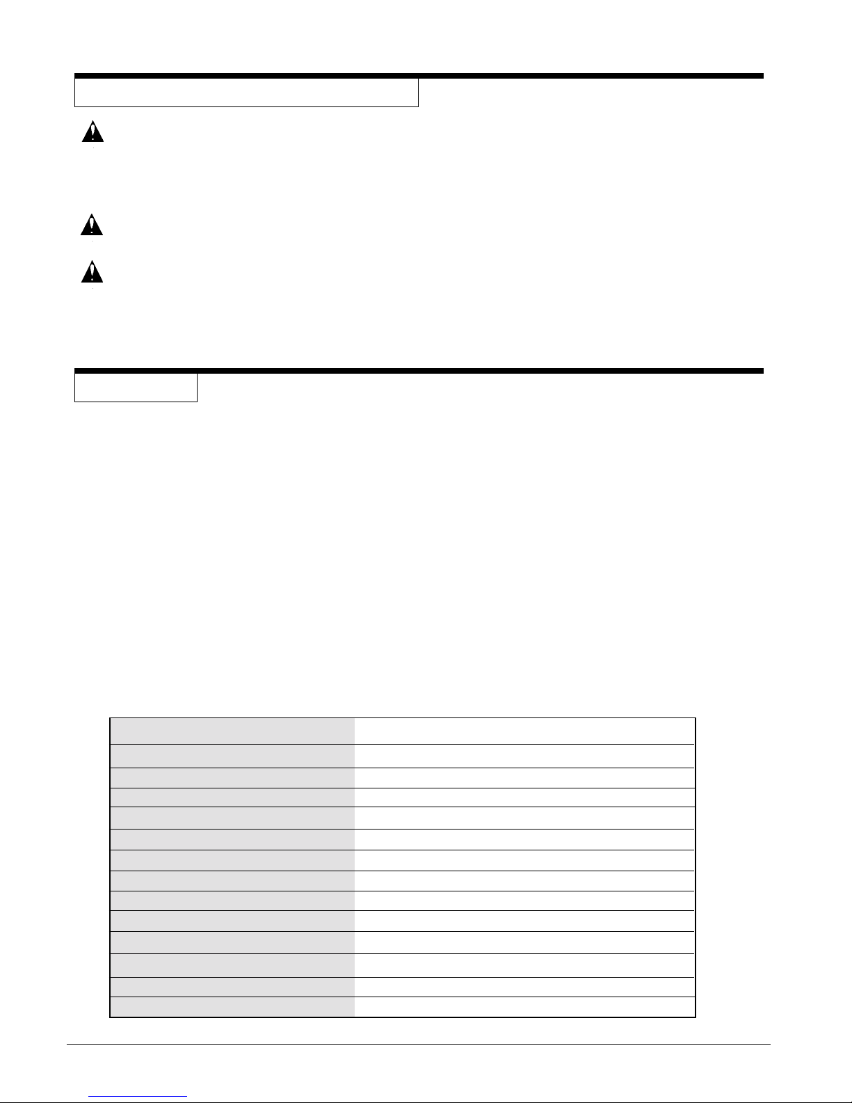
INTRODUCTION
• The Model 515 is an extractor for cleaning carpet. When used with a floor tool, the machine applies cleaning
solution to the carpet and removes the dirty solution and soil from the carpet.
• The extractor has controls to start the pump for the solution and the motor for the vacuum. The floor tools
have controls to release the solution and to operate the brush.
• The extractor has a demand pump. The pump starts when the solution lever on the floor tool is activated.
The pump stops when the lever is released.
NOTE: When using the extractor to clean carpets, follow this procedure:
1. Do not walk on freshly cleaned carpets for at least four hours or until the carpet is dry to touch.
2. Do not remove aluminum or plastic pieces that have been placed under the legs of furniture until
the carpet is dry.
3. Do not allow children or pets to crawl or walk around on the damp carpet.
4. Vacuum right after the carpet is dry and then vacuum the carpet once a week as needed.
Electrical 120 V 50/60 Hz.
Amps 9 amps
Solution Pump 60 psi
Solution Tank 15 gal
Recovery Tank 5 gal
Solution Flow 1.47 GPM (Open Flow)
Vacuum Motor 2 hp
Power Cable 35', 3-wire grounded (10.7m)
Wheels 4 - 2" (5.1 cm)
Dimensions 25"L (63.5cm) x 17½"W (44.5cm) x 26¼"H (56.5cm)
Weight 45 lbs.
Shipping Weight 70 lbs.
Warranty 1 year
Sound Level
Page 4
CLARKE TECHNOLOGY EXT 515 Operator's Manual
Page 36
CONTROLS and MACHINE FEATURES
The Vacuum Motor Switch
The vacuum motor switch is on the back of the machine.
Put the switch in the "I" position to start the motor. Put
the switch in the "O" position to stop the motor.
The Switch To Activate The Pump
The switch to start/stop the pump motor is on the back
of the machine. Put the switch in the "I" position to start
the pump motor. Press the lever on the floor tool to
activate the pump. Release the levers on the floor to stop
the pump. Put the switch in the "O" position to stop the
pump motor.
NOTE: While the machine is in operation, the pump
will shut-off automatically when it reaches full
pressure. The pump will automatically turn on
when the pressure decreases.
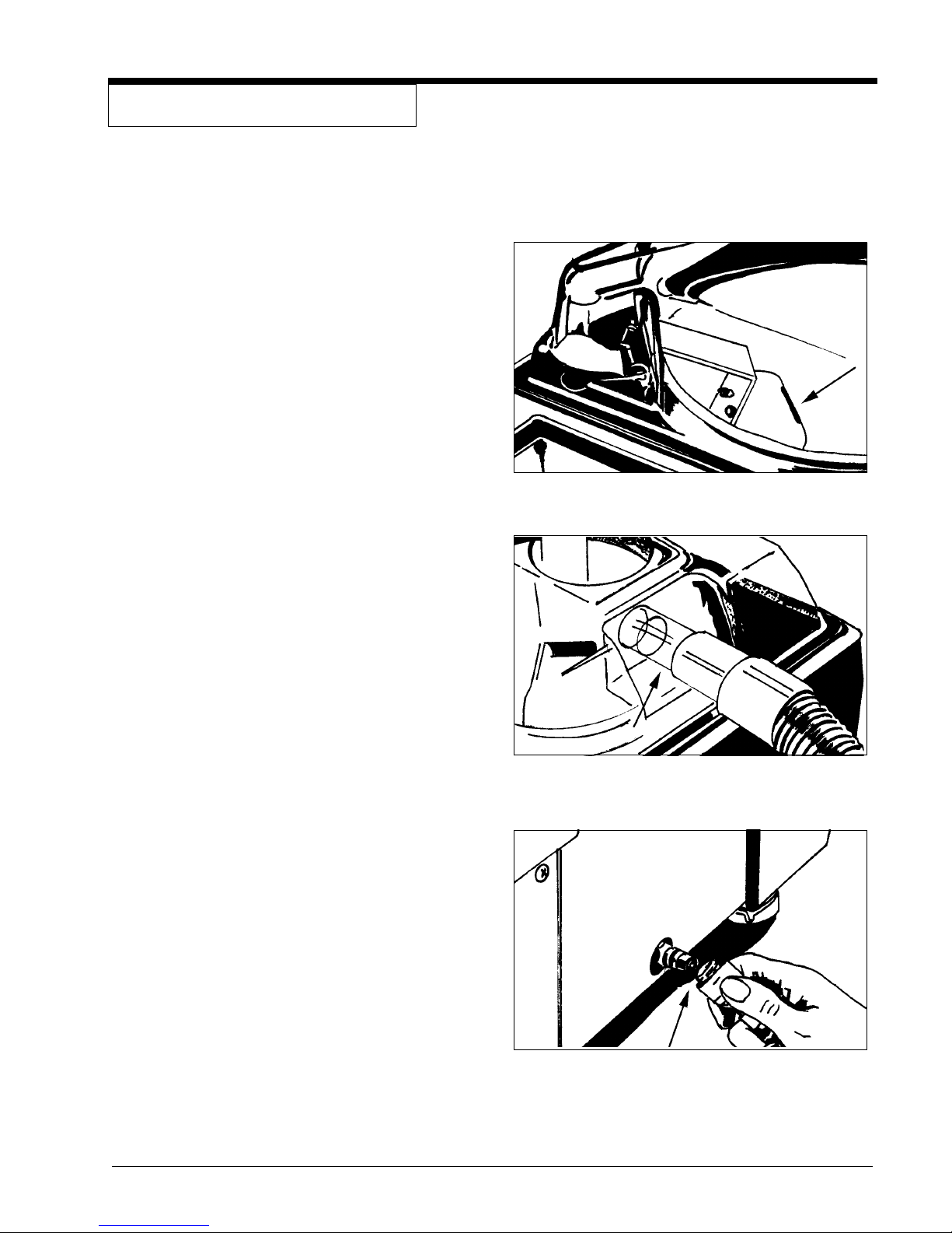
Figure 1
The Float Shut-Off See figure 1
The float shut-off is in the recovery tank. When the liquid
raises the float, the air stops moving through the machine.
The Vacuum Hose Connector See figure 2
The vacuum hose connector is on the dome assembly.
The Solution Hose Connector See figure 3
The solution hose connector is on the lower part of the
extractor, below the vacuum hose connector.
The Recovery Tank
The recovery tank is in the top of the machine. Make sure
the white pail is in the tank when the machine is running.
The Solution Tank
Figure 2
The solution tank is in the top of the machine next to the
recovery tank.
CLARKE TECHNOLOGY EXT 515 Operator's Manual Page 5
Figure 3
Page 37
HOW TO PREPARE THE MACHINE FOR OPERATION
To prepare the machine for operation, follow this procedure:
1. Connect the vacuum hose to the hose connector
on the extractor and to the end of the vacuum
tube on the floor tool.
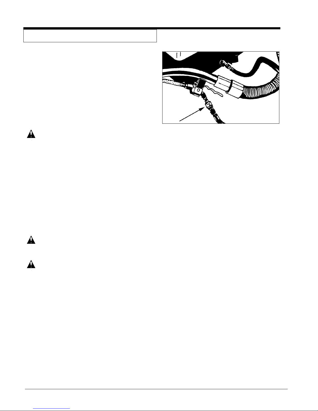
2. Connect the solution hose to the extractor and
the floor tool. To fasten the quick disconnect
fitting, slide the knurled collar on the female
coupling away from the opening. Push the male
coupling into the female coupling. See figure 4
WARNING: Do not use water that is hotter than
140°F.
3. Before moving the extractor onto the carpet, put
clean hot water into the solution tank.
4. Add a cleaning chemical, such as Clarkare
Extractor Concentrate, to the hot water. For the
correct amount, follow the directions shown on
the container.
5. If the extractor removes an excess amount of
foam from the carpet, add a de-foamer such as
Clarkare® De-foamer Concentrate to the recovery tank. The amount needed will vary according
to the amount of detergent already in the carpet.
CAUTION: To prevent damage, use a water-
based de-foamer rather than an
oil-based de-foamer.
CAUTION: Do not leave the extractor or
other cleaning machines or tools
on the carpet when not in use.
Cleaning solution in the machines
and tools can leak onto the carpet and cause light spots or stains.
Figure 4
®
NOTE: To order Clarkare® Extractor Concentrate, order
part no. 398421. To order Clarkare® Defoamer,
order part no. 398420.
For instructions on preparation and operation of your floor
tool or power brush tool, read the operator's manual given
with your floor tool or power brush tool.
Page 6
CLARKE TECHNOLOGY EXT 515 Operator's Manual
Page 38
INSTRUCTIONS FOR CONNECTION TO THE
POWER SUPPLY AND ELECTRICAL GROUND - 120 V
CAUTION: This machine will operate only on an AC
frequency and on the specified electrical
voltage shown on the nameplate. Make
sure you have the correct frequency and
voltage before connecting the power
cord to an outlet.
Plate
Screw
This machine must be connected to an electrically ground
circuit in order to protect the operator from electric shock. This
machine has an approved power cord with three conductors as
well as a plug with three terminals. Connect the plug to a three
holed receptacle. For maximum protection against electric
shock, use a circuit that is protected by a ground fault circuit
interrupter.
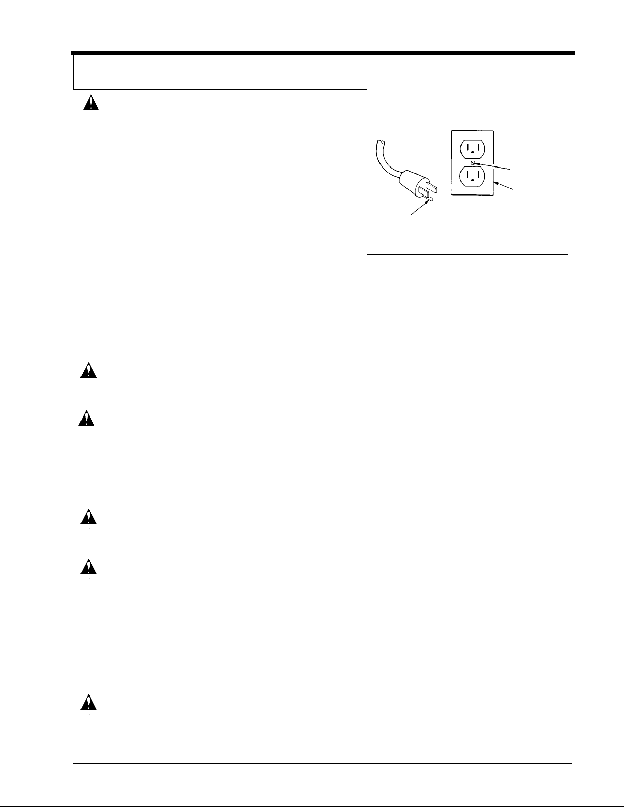
This machine uses a 120 volt AC 50/60 cycle electrical circuit.
Make sure you have the correct frequency and voltage before
connecting the power cord to an outlet. The machine has a plug
as shown in Figure 5. If a receptacle connected to the electrical
ground as shown in Figure 5 is not available, contact an
electrical contractor. Do not us an adapter.
WARNING: To prevent possible electric shock, pro-
tect the machine from rain. Keep the
machine in a dry building.
WARNING: To prevent possible electric shock, al-
ways use a 3-wire electrical system connected to the electrical ground. For
maximum protection against electrical
shock, use a circuit that is protected by a
ground fault circuit interrupter. Consult
your electrical contractor.
Ground Pin
Outlet must be
connected to
the electrical
ground
Figure 5
WARNING: Do not cut, remove, or break the ground
pin. If the outlet does not fit the plug,
consult your electrical contractor.
WARNING: If the cords or plugs are worn or dam-
aged in any way, have them replaced by
an authorized service person.
Extension Cords
Use only an approved extension cord with three conductors, a
plug with three terminals and a three-holed connector body.
This machine has a power cord with a wire size of 16 AWG.
(AWG stands for American Wire Gauge).
CAUTION: If you use an extension cord, use one that
has a minimum wire size of 14 AWG. Be
sure your extension cord is no longer
than 50 ft. Do not join two extension
cords.
CLARKE TECHNOLOGY EXT 515 Operator's Manual Page 7
Page 39
INSTRUCTIONS FOR CONNECTION TO THE
POWER SUPPLY AND ELECTRICAL GROUND - 230 V
CAUTION: This machine will operate only on an AC
frequency and on the specified electrical voltage shown on the nameplate.
Make sure you have the correct frequency and voltage before connecting
the power cord to an outlet.
This machine must be connected to an electrical ground circuit
in order to protect the operator from electric shock. This
machine has an approved power cord with two main conductors
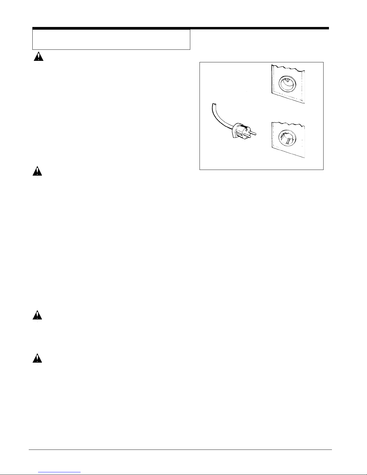
and one earthing conductor. Connect the plug to the type of
receptacle shown in figure 6. The green and yellow conductor
in the cord is the ground wire. Never connect this wire to any
terminal other than the ground terminal.
WARNING: Always use this machine with an AC
three-conductor electrical system connected to the electrical ground. Replace any worn, cut or damaged cords.
Replace any damaged plugs, receptacles, or connector bodies. Do not
move the machine over an electrical
cord. Always lift the cord over the machine.
Extension Cords
Pin Earthing Contact
European Plug
Side Earthing Contact
Figure 6
Use only an approved extension cord with two main conductors, and one earthing conductor. This machine has a power
cord with a wire size of 1.5mm2.
WARNING: If you use an extension cord, use one
that has a minimum wire size of 1.5mm2.
Be sure your extension cord is no longer
than 15 meters. Do not join two extension cords.
WARNING: Do not cut, remove or break the ground
terminal. Do not try to fit a three-terminal plug into a receptacle or connector
body that does not fit the plug. If the
receptacle or connector body does not
fit the plug, see your authorized Clarke
Dealer to get an authorized person to
make the connection.
Page 8
CLARKE TECHNOLOGY EXT 515 Operator's Manual
Page 40
MACHINE OPERATING INSTRUCTIONS
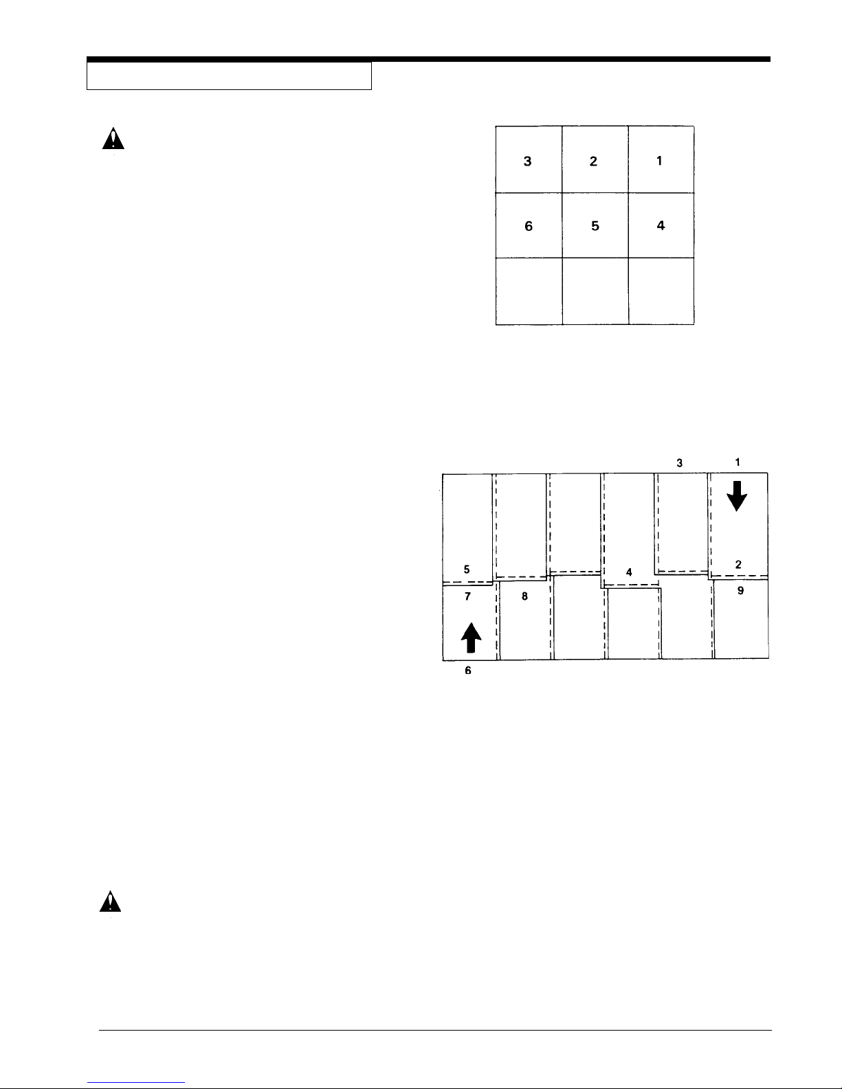
How to Clean an Area of Carpet See Figure 7
WARNING: Do not use water that is hotter
than 140°F.
To clean an area of carpet, follow this procedure:
1. Start the pump for the solution and the motor for the
vacuum on the extractor.
2. Begin at the right-hand corner of the carpet.
3. Hold the floor tool at the angle that gives the best
vacuum seal between the tool and the carpet.
4. Apply pressure to the lever for solution release. Pull
the tool toward you at a slow, steady speed. To
remove as much solution as possible, release the
lever before you stop moving backward.
5. To clean the edge of a room, move the tool along the
baseboard until the edge of all the carpet is cleaned.
6. To clean a small area of carpet, clean the carpet in
sections three feet square. As you make more
passes, repeat one inch of the area already cleaned.
7. To remove more liquid from the carpet, make passes
over the area already cleaned, but do not apply
pressure to the lever for the solution.
Figure 7
How To Clean A Larger Area Of Carpet See Fig. 8
To clean a larger area of carpet, follow this procedure:
1. Begin at the right-hand corner of the carpet.
2. Make a pass halfway along the edge of the carpet.
Pull the tool backward at a steady speed.
3. Move to the edge of the carpet. Make another pass
next to your first pass.
4. As you make more passes, repeat one inch of the
area already cleaned. If you use a power brush tool,
repeat one inch of the area already cleaned by the
brush. Make each pass four inches different in length
to prevent making a line in the center of the carpet.
5. Make more passes until half of the carpet is cleaned.
To remove more liquid from the carpet, make passes
over the area already cleaned, but do not apply
pressure to the lever for the solution.
6. Move to the right-hand corner of the part of the carpet
not yet cleaned.
7. Make a pass halfway along the edge of the carpet.
8. As you make passes, repeat one inch of the area
already cleaned.
9. Make more passes until all of the room is cleaned.
Figure 8
CAUTION: ALTO U.S. Inc. will not be held li-
able for damage to the carpet, or
poor results because of the
operator's lack of ability.
CLARKE TECHNOLOGY EXT 515 Operator's Manual Page 9
Page 41
MAINTENANCE
WARNING: Maintenance and repairs must
be done by authorized personnel only. Keep all fasteners tight.
Use only genuine Clarke parts.
WARNING: Do not operate this machine un-
less it is completely assembled.
NOTE: For maintenance of the floor tools or power
brush tools, read the manual given with the tools.
After Each Use of the Machine
1. To remove unused cleaning solution from the
solution tank, put the end of the vacuum hose in
the solution tank. Start the vacuum motor. Stop
the motor when the tank is empty.
2. To prevent damage to the valves and jets, flush
one gallon of clean water through the solution
system and the tools.
3. Disconnect the power cord from the outlet.
4. Remove the recovery tank cover.
5. Lift the pail and discard the solution.
6. Rinse the pail with clean water.
7. Use a dry cloth to wipe the tools and both tanks,
inside and out.
8. Apply a small amount of silicone lubricant to the
quick-disconnect fittings. To prevent damage to
the O-rings, do not use an oil lubricant.
9. Inspect the gasket or the vacuum shut-off valve. If
the gasket is damaged, replace the gasket.
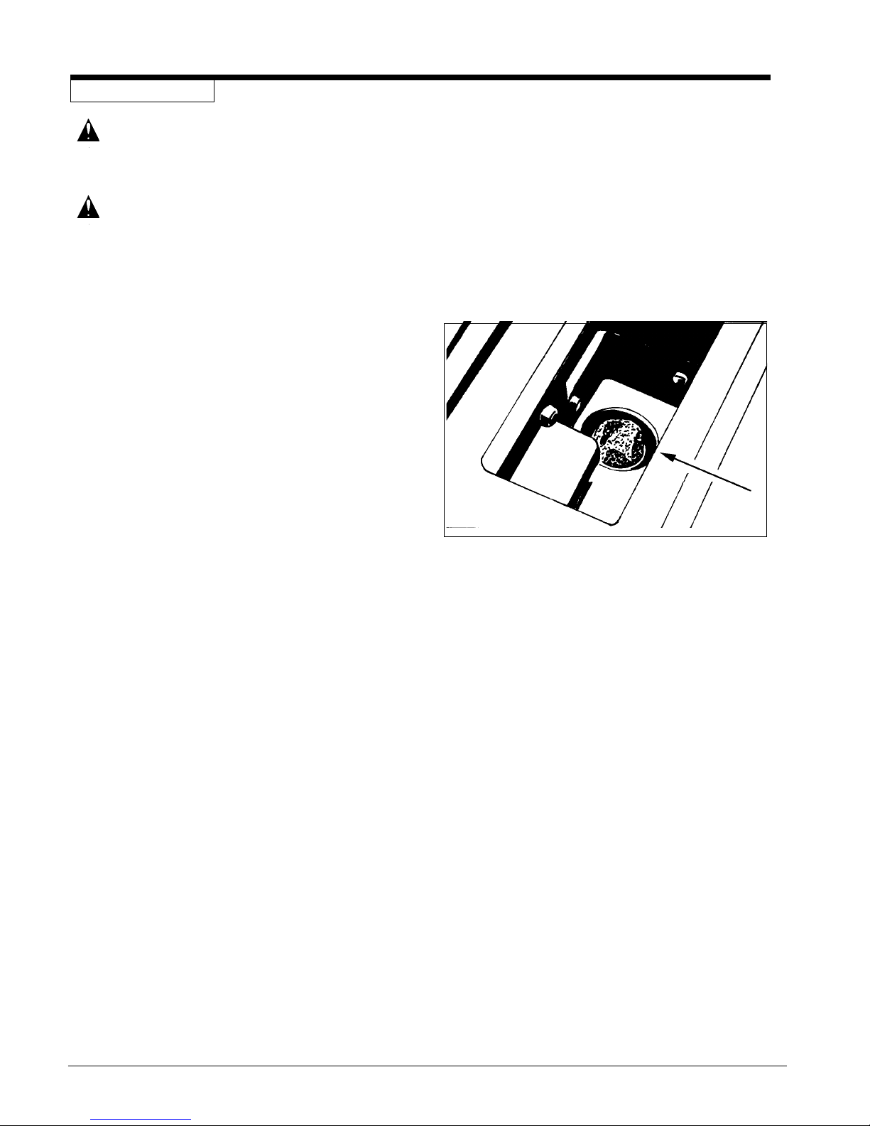
10. Inspect and clean the filter screen in the bottom
of the solution tank. See figure 9. To remove the
filter screen, turn the filter counterclockwise. To
install the filter, turn the filter clockwise.
Figure 9
Page 10
CLARKE TECHNOLOGY EXT 515 Operator's Manual
Page 42
MAINTENANCE (CONT)
How To Prevent Damage From Freezing Temperatures
To prevent damage from freezing temperatures follow
this procedure:
1. Use the vacuum hose to remove all the solution
from the clean solution tank.
2. Connect the solution hose to the extractor and a
floor tool.
3. Put approximately 1 quart of antifreeze solution in
the solution tank.
4. Put the switch for the pump in the "I" position.
5. Put the end of the floor tool in the recovery pail.
6. Press the lever on the floor tool to activate the
pump.
7. Make sure the solution runs through the system.
8. Release the lever on the floor tool to stop the
pump.
9. Flush the antifreeze solution from the system
before using the extractor.
10.Make sure the machine is the same temperature
as the room before using the machine.
Electrical
WARNING: Electrical repairs must be done by
authorized personnel only.
WARNING: After electrical repairs are done to
the machine, the machine must be
tested for electrical safety.
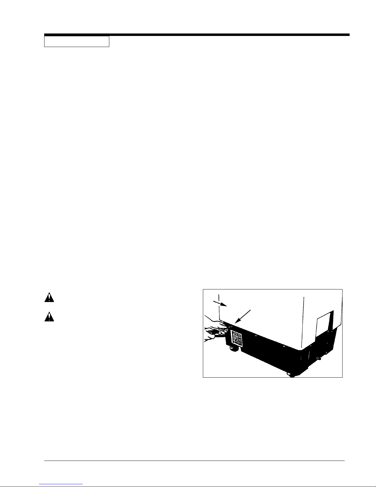
How To Get Access To The Pump and Vacuum
Motor
To get access to the pump and the vacuum motor,
follow this procedure:
1. Remove the dome.
2. Empty both tanks.
3. Remove the pail.
2
1
Figure 10
4. Remove the ten screws from the lower housing
(1).
5. Lift the upper housing from the machine (2).
See figure 10.
CLARKE TECHNOLOGY EXT 515 Operator's Manual Page 11
Page 43
MAINTENANCE (CONT)
Maintenance Of The Motor
This machine has a vacuum motor that uses carbon
brushes. The carbon brushes in the motor must be
checked every three months, or every 500 hours of
operation, whichever comes first. If either of the brushes
is shorter than 3/8 inch, replace both of the carbon
brushes.
How To Check The Commutator And The Carbon
Brushes
WARNING: Electrical inspections must be made
by a person authorized to make
electrical repairs.
To check the commutator and the carbon brushes follow
this procedure:
1. Disconnect the power cord from the electrical outlet.
2. Remove the dome.
3. Empty both tanks.
4. Remove the pail.
5. Remove the ten screws from the lower housing.
6. Lift the upper housing from the lower housing.
7. Put the machine on its side.
8. Disconnect the ground wire.
9. Remove the two screws from the bottom of the
machine that hold the motor bracket.
10. Remove the plastic motor cover.
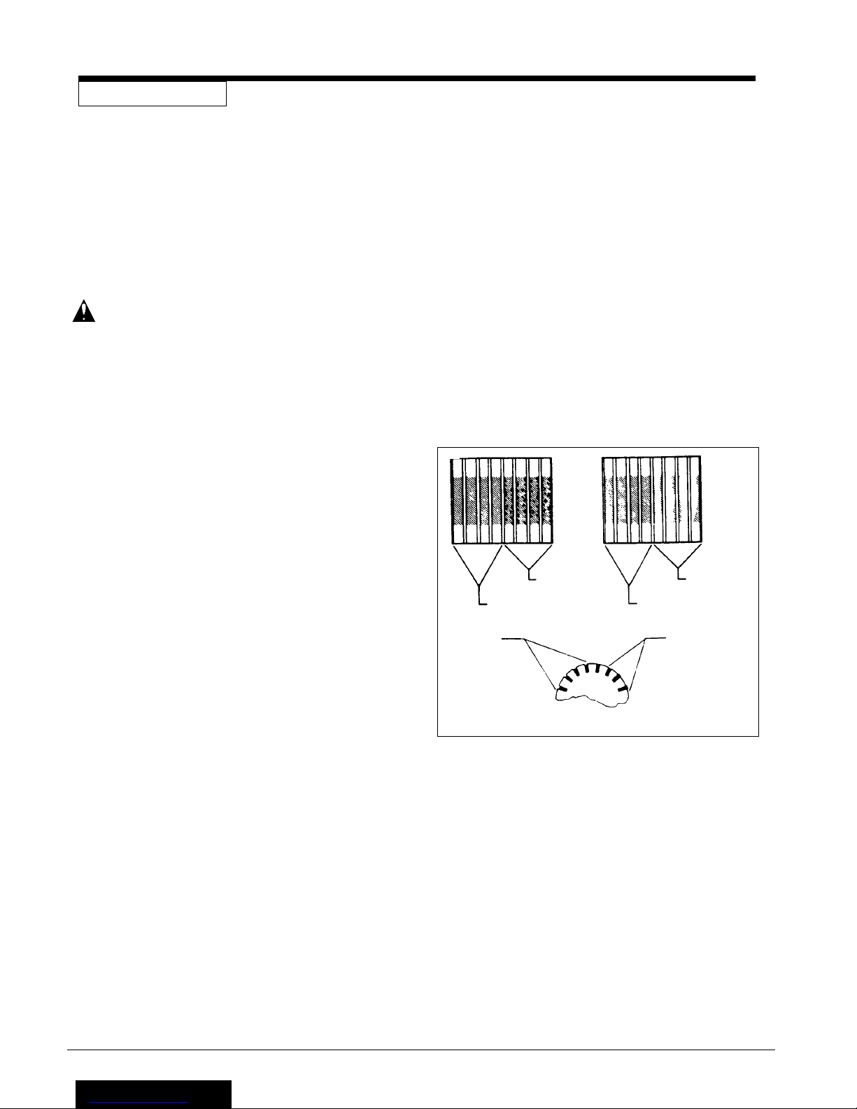
11. Inspect the commutator. See figure 11. Take the
machine to a Clarke authorized repair location if you
see any of the following conditions:
a.Small holes in the surface of the commutator.
See "A" in figure 11.
b.Uneven color. Look for an even dark brown
color. Clean areas or very dark areas indicate a
problem.
See "B" in figure 11.
c. High mica. The mica insulation must be lower
than the commutator bars. See "C" in figure 11.
12. To check the carbon brush assemblies, remove the
two screws from the holding bracket.
13. Remove the brackets.
14. Remove the carbon brush assemblies.
15. Check the carbon brush assembly. Replace both
carbon brush assemblies if either carbon brush is
3
shorter than
8
inch. If either brush is shorter than ½
inch, order replacement brushes. Be ready to
replace both carbon brushes earlier than the normal
inspection time.
16. Put the motor brushes in position.
17. Using the two screws, install the bracket that holds
the carbon brushes.
18. Install the plastic motor cover.
19. Connect the ground wire.
20. Install the motor holding bracket.
21. Install the lower housing to the upper housing.
GOOD
UNEVEN
GOOD
SMALL
HOLES
GOOD
AB
HIGH MICA
C
Figure 11
Page 12
CLARKE TECHNOLOGY EXT 515 Operator's Manual
Page 44
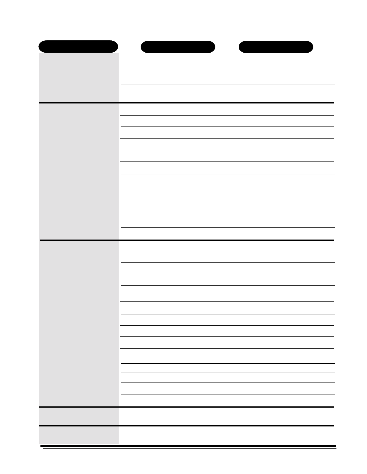
HOW TO CORRECT PROBLEMS IN THE MACHINE
Problem
The machine will not run.
There is no suction.
1. The machine has no power.
2. The power cord is damaged.
1. The vac motor does not run.
2. The vac motor switch is defective.
3. There is a loose motor connection.
4. There is an obstruction in the vacuum
hose.
5. The recovery tank is full.
6. The dome gasket is worn or damaged.
7. The dome is not in the correct position.
8. The internal vac hose is damaged
or stopped.
9. The dome is damaged.
ActionCause
1. Make sure the machine is connected to the
correct frequency and voltage, and all connections are tight.
Make sure the plug is in the electrical outlet.
2. Contact an authorized service person to replace
the cord.
1. Put the switch for the vacuum in the "I" position.
2. Contact an authorized service person.
3. Contact an authorized service person.
4. Remove the obstruction.
5. Remove the liquid from the tank.
6. Contact an authorized service person to replace
the gasket.
7. Put the dome in the correct position.
8. Contact an authorized service person.
9. Replace the dome.
There is no pressure.
10.The motor brushes are worn.
11.A wrong size pail is being used.
1. The switch is in the "OFF" position.
2. The pressure switch is damaged.
3. The pump motor will not run.
4. The pump motor brushes are worn.
5. The quick disconnect fitting is dirty
or stopped.
6. The solution hose is bent.
7. The pump is worn.
8. The pump switch is defective.
9. The pump connections are loose.
10.The pump intake and oulet valves are
worn.
11.The thermo protector is open.
12.The solution tank is empty.
13.The intake screen is dirty.
10.Replace the motor brushes.
11.Use only the pail given with the machine.
1. Put the switch in the "I" position.
2. Contact an authorized service person.
3. Contact an authorized service person.
4. Contact an authorized service person.
5. Contact an authorized service person.
6. Straighten the hose. Replace if damaged.
7. Contact an authorized service person.
8. Contact an authorized service person.
9. Contact an authorized service person.
10. Contact an authorized service person.
11. Contact an authorized service person.
12. Fill the solution tank.
13. Clean the screen.
14.The rectifier in the pump motor is bad.
The solution tank leaks.
The recovery tank overflows.
1. The intake gasket is worn.
2. The tank is damaged.
1. The float is dirty or damaged.
2. There is too much foam.
3. The float gasket is dirty or damaged.
CLARKE TECHNOLOGY EXT 515 Operator's Manual Page 13
14. Contact an authorized service person.
1. Contact an authorized service person.
2. Contact an authorized service person.
1. Clean the float. Replace if damaged.
2. Put defoamer in the solution. Order P/N 398420.
3. Clean the gasket. Replace if damaged.
Page 45

NOTES
Page 14
CLARKE TECHNOLOGY EXT 515 Operator's Manual
Page 46

EXT 515
Extractor
Section II
Parts and Service Manual
CLARKE TECHNOLOGY EXT 515 Operator's Manual Page 15
(78165A)
Page 47
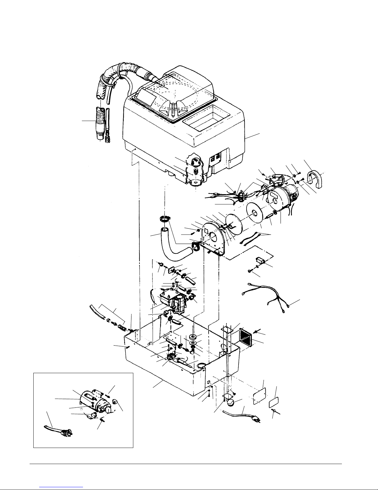
30
CLARKE TECHNOLOGY EXT-511
Assembly Drawing #1 9/98
12
12
11
10
9
56
8
67
7
5
6
10
4
57
3
18
6
7
56
10
13
13
14
17
9
16
55
15
65
10
9
51
28
61
52
62
53
10
53
30
52
25
29
28
32
38
34
19
59
24
60
31
35
22
9
20
33
23
26
27
22
9
54
21
25
39
22
24
23
37
29
24
24
23
36
63
64
66
44
43
42
41
40
22
6
49
50
51
45
46
47
48
45
Page 16
CLARKE TECHNOLOGY EXT 515 Operator's Manual
Page 48

CLARKE TECHNOLOGY EXT-511
Assembly Drawing #1 Parts List 9/98
Item # Description
Part No. Item # Description
Qty.
1 728535 Strainer, Solution Tank 1
2 60306A Adapter, Filter 1
3 K 38913C Tank Ref.
4 752020 Clamp, Hose .81 to 1.75 range 2
5 35131A Hose, Vacuum 1
6 85329A Screw, ¼-20 x
5
/8 Pan 7
7 980614 Washer, ¼ Shakeproof 5
8 65903A Mount, Vac Motor 1
9 K 980603 Washer, #10 Shakeproof 7
10 85364A Screw, #10-32 x 3/8 14
11 60307A Adapter, Vac Motor 1
12 911177 Nut Wire 4
13 49620A Wire Harness Assembly 1
14 899254 Wire Tie 3
15 34212A Gasket, Vac Motor Adapter 1
16 44906A Motor, Vac 120V 1
44907A Motor, Vac 230V 1
17 85506A Screw, #10-24 x ½, Type 23 1
18 34234A Gasket, Intake Air 1
19 737140 Quick Disconnect, Male 1
20 725729 Nipple, 1/8 Close Pipe 1
21 66617A Plate, Quick Disconnect Mt. 1
22 920200 Nut, #10-24 Hex 5
23 722030 Clamp, Hose 4
24 694116 Hose 2
25 85323A Screw, #10-24 x ½ 3
1
26 50300A Adapter,
/8p to 3/8 Hose 1
27 81200A Nut, 1/8 Pipe Lock 1
28 45900A Pump, 120V 1
697011 Pump, 230V 1
29 692870 Elbow, Swivel Barb 2
30 15604A Hose Assembly Applicator Ref.
31 964004 Screw, M5 x 0.8 x 16 PN 2
32 672012 Clamp, Cord 1
33 964003 Screw, M5 x o.8 x 20 Pan 2
Part No.
34 672011 Clamp, Strain Relief 1
35 670811 Bracket, Strain Relief 1
36 38002A Strain Relief 1
37 980646 Washer, ¼ Plain 2
38 K 30801B Base 1
39 502406 Coupling, ¼P to 3/8 Hose 1
40 232801 Elbow, Street 1
41 833401 Gasket, Drain 1
42 980630 Washer,
43 920264 Nut,
44 66633A Plate, Nut 4
45 930074 Pop Rivet, 1/8 x ¼ x 5/16 6
46 603801 Grill, Rear Housing 1
47 66634A Plate, Label Mounting 1
48 Label, Serial No. 1
49 85328A Screw, ¼-20 x ½ 16
50 52100A Caster, 2" Ball 4
51 42164B Cord, Extension 120V 1
42167A Cord, Extension 230V 1
52 722851 Elbow, 3/8 St. 230V Only 2
53 720270 Adapter, 3/8H x 3/8NPT 230V only 2
54 85353A Screw, #10-24 x
55 962453 Screw, ¼-20 Set 1
56 954010 Wire Assembly, Ground 1
57 49033A Wire Ground Lead, 120V only 1
58 838216 Spacer, 120V only 2
59 980982 Washer, 1#C SAE 120V only 4
60 85361A Screw, #10-32 x 1 Pn 120V 4
61 85307B Screw, #10-32 x 5/8 230V only 4
62 980982 Washer, #10 Plain 230V only 4
63 K 47201A Filter (CE only) 1
64 K 962333 Screw (CE only) 6
65 K 49310A Lead Assembly (CE only) 2
66 K 49642B Harness (CE only) 1
67 K 77094A Label (CE only) 1
3
/4 I.D. Plain 1
3
/4-16 Hex Jam 1
5
/8 Pan 2
Qty.
NOTE: K indicates a change has been made since
last publication of this manual.
CLARKE TECHNOLOGY EXT 515 Operator's Manual Page 17
Page 49
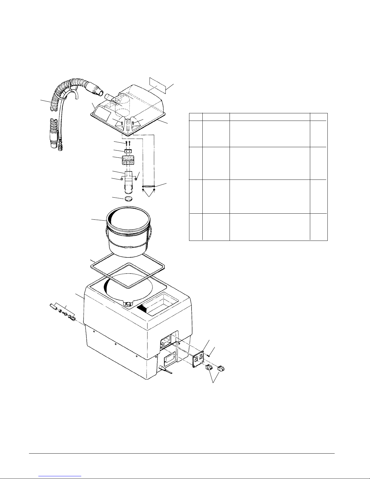
CLARKE TECHNOLOGY EXT-511
Assembly Drawing #2 & Parts List 5/86
3
1
2
Item # Description
5
5
4
Part No.
1 15604A Hose Assembly 1
Qty.
2 73289A Label, Warning 1
3 73290A Label, Instruction 1
4 13001A Dome and Label Assembly 1
5 85319A Screw, #8-32 x ½ Pan 2
6 85350A Screw, #8-32 x 2½ Pan 2
7 62401A Clamp, Float 1
8 33801A Float 1
9 61110A Bracket, Float 1
10 34213A Gasket, Float Shut-Off 1
12
6
7
8
9
12
11
11 67104A Rod, Float Pivot 1
10
12
12 920065 Nut, #8-32 ESNA 4
13 36900A Pail, Recovery 1
14 34235A Gasket, Dome Assembly 1
13
15 38913A Tank 1
16 85364A Screw, #10-32 x
3
/8 4
17 37303A Plate, Switch 1
18 47316A Switch, On- Off 2
14
Page 18
15
1
17
16
18
CLARKE TECHNOLOGY EXT 515 Operator's Manual
Page 50
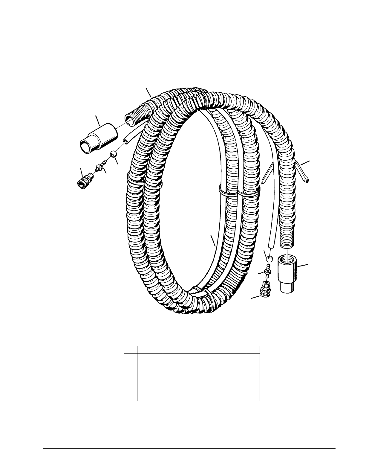
CLARKE TECHNOLOGY EXT- 511
10 ft. Hose Assembly Drawing & Parts List 5/86
1
2
3
5
6
4
7
5
2
4
3
CLARKE TECHNOLOGY EXT 515 Operator's Manual Page 19
Item # Description
Part No.
1 634117 Hose, Vacuum 1½" I.D. x 10' 1
2 732440 Cuff, Vacuum Hose 2
3 737141 Quick Disconnect, Female 2
4 690209 Adapter, 3/8 Hose to 1/8 NPT 2
5 693302 Ferrule 2
6 899254 Tie, Nylon Cable 9
7 35110A Hose, Applicator 1
Qty.
Page 51
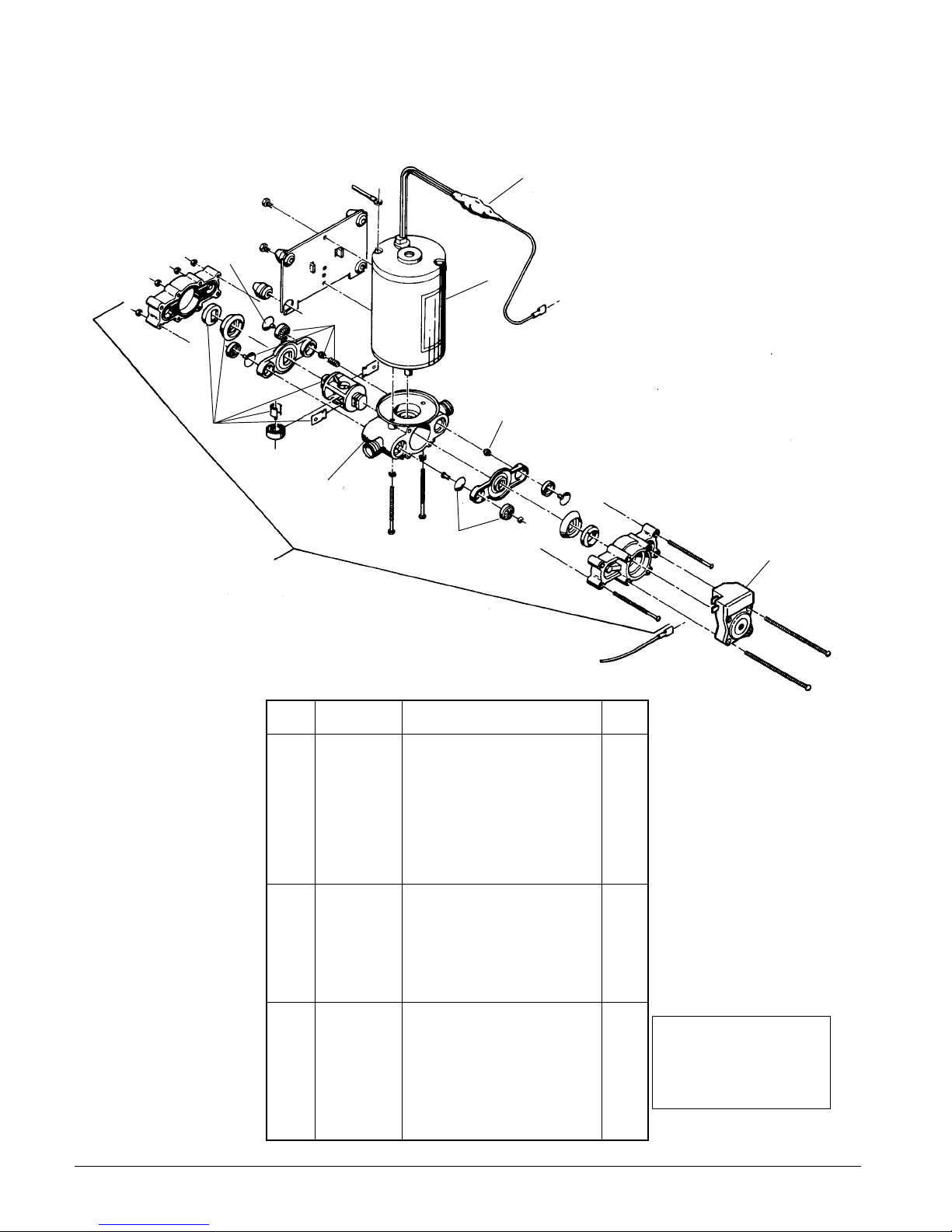
CLARKE TECHNOLOGY EXT- 511
Pump Replacement Parts 5/86
2
5
1
6
6
3
8
5
4
Ref # Part No. Description Req.
1 56002A Motor
2 912232 Rectifier
3 697072 Piston and Eccentric
Lock Ring 2
Cap Piston 2
Eccentric 1
Bearing 1
Wear Plate 2
Piston 1
4 54805A Head Assembly Complete
5 692972 Elastomer Assembly
Seat Valve 4
Valve 3
Diaphragm 2
Valve 1
O'Ring 1
6 59701A Valve By-Pass
Seat Valve 2
Valve 2
Spring 1
Valve Stem 1
Valve Stem 1
7 912233 Switch Micro
8 54807A Pump Housing
7
No.
SERVICE PARTS FOR
230V PUMP #697011
16400A Kit - Service
16401A Kit - Brush (Motor)
46800A Semiconductor
Asm. - Rectifier
47300A Switch - Pressure
Page 20
CLARKE TECHNOLOGY EXT 515 Operator's Manual
Page 52
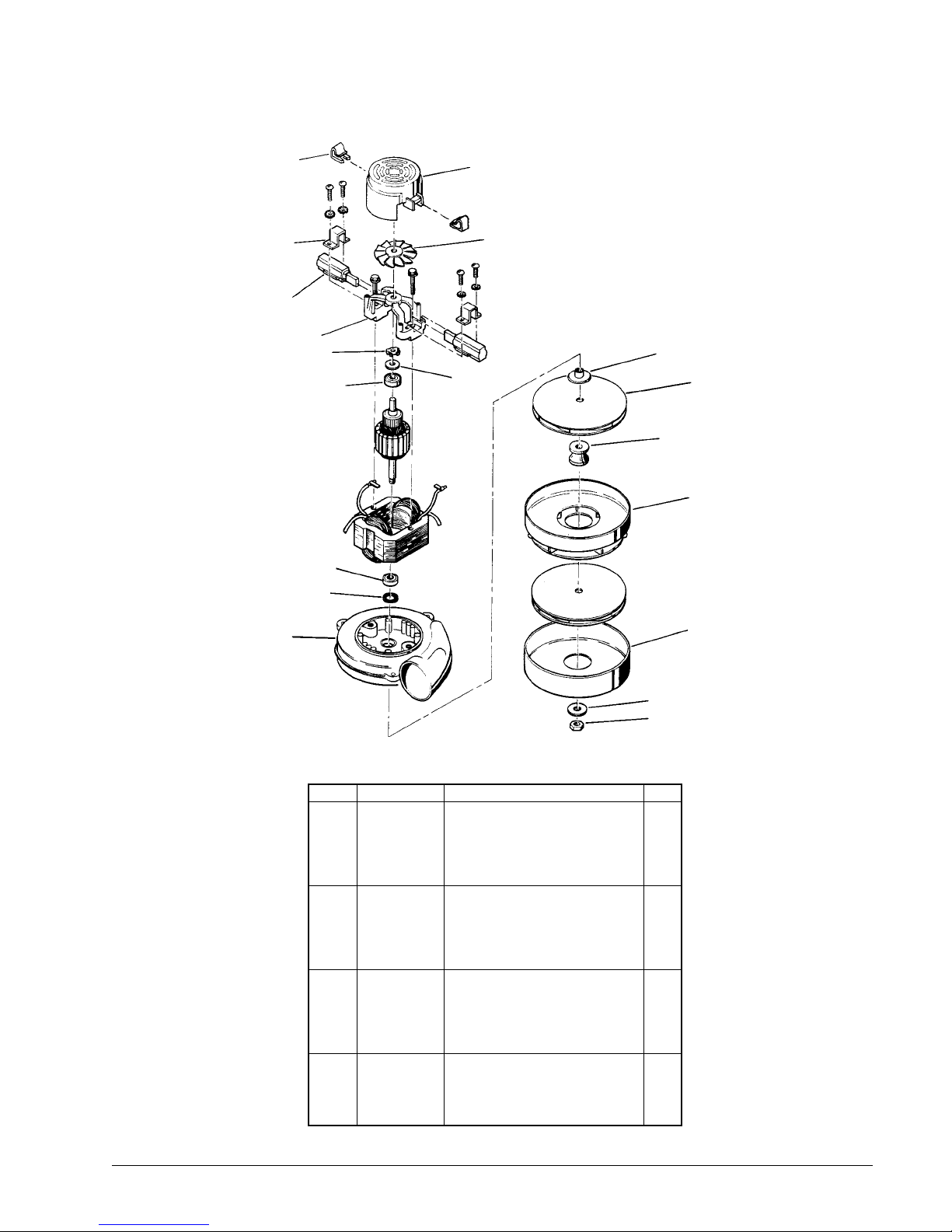
CLARKE TECHNOLOGY EXT- 511
Motor 120V #44906A - 9/98
1
4
5
6
7
9
10
11
2
3
13
8
14
15
16
NOTE: K indicates
a change has been
made since last
publication of this
manual.
12
Ref # Part No. Description Qty
1 51913A Clip (Optional) 2
2 54809A Housing, Vent 1
3 53905A Fan 1
4 51914A Clamp 2
5 K 51401A Brushes, Carbon (Set of 2) 1
6 50618A Bracket, End, Commutator 1
7 58600A Load Spring 1
8 53100A Disc 1
9 902679 Ball Bearing 1
10 902648 Ball Bearing 1
11 59803A Washer 1
12 50610A Bracket, End, Fan 1
13 58501A Spacer 1
14 653012 Fan, Vacuum 2
15 658201 Spacer 1
16 53907A Fan, Stationary 1
17 57910A Shell, Fan 1
18 980205 Washer 1
19 920329 Nut 1
17
18
19
CLARKE TECHNOLOGY EXT 515 Operator's Manual Page 21
Page 53
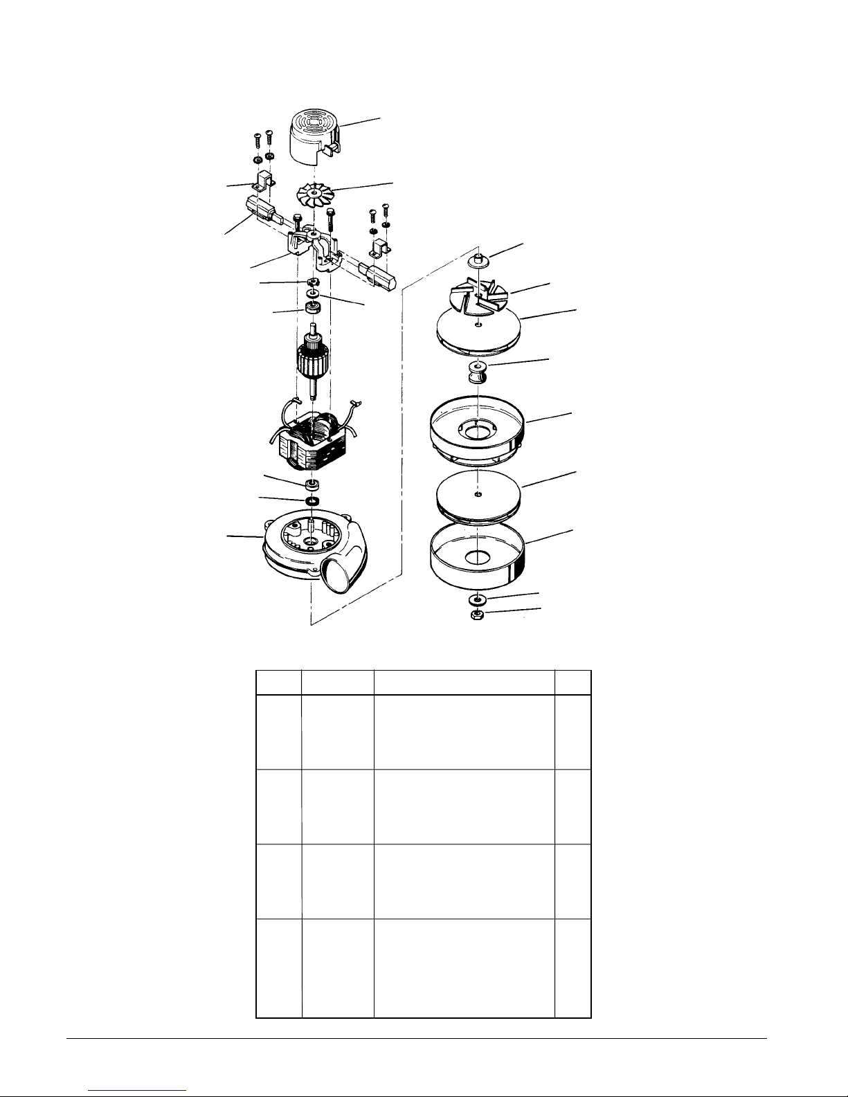
CLARKE TECHNOLOGY EXT- 511
Motor 230V #44907A - 9/98
2
5
12
4
3
13
6
7
9
8
20
14
15
16
10
21
11
17
NOTE: K indicates
a change has been
made since last
publication of this
manual.
18
19
Ref # Part No. Description Qty
1
2 54809A Housing, Vent 1
3 53905A Fan 1
4 51914A Clamp 2
5 K 40813A Brushes, Carbon 2
6 50618A Bracket, End, Commutator 1
7 58600A Spring, Load 1
8 53100A Disc 1
9 902679 Ball Bearing 1
10 902648 Ball Bearing 1
11 59803A Washer 1
12 50610A Bracket, End, Fan 1
13 58501A Spacer 1
14 653012 Fan, Vacuum 1
15 658201 Spacer 1
16 53907A Fan, Stationary 1
17 57910A Shell, Fan 1
18 980205 Washer 1
19 920329 Nut 1
20 53906A Fan 1
21 653012 Fan- Rotating 1
Page 22
CLARKE TECHNOLOGY EXT 515 Operator's Manual
Page 54
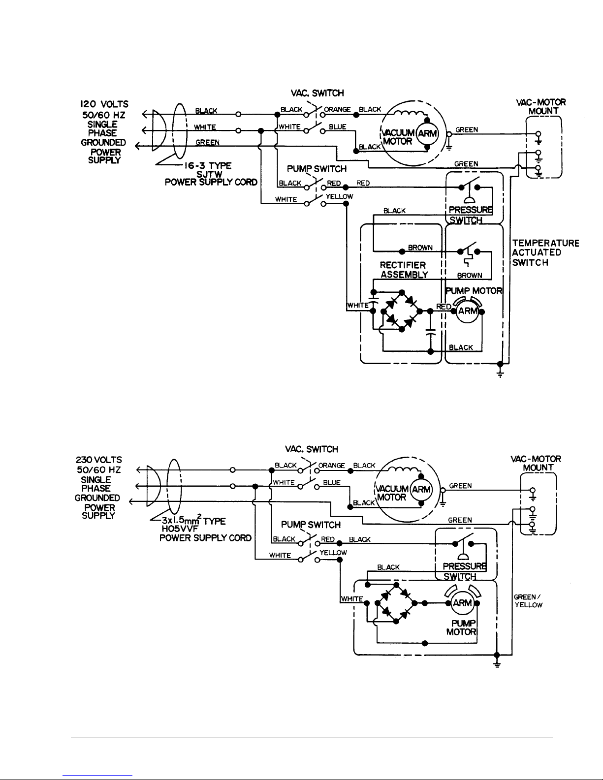
CLARKE TECHNOLOGY EXT- 511
Wiring Diagram 120V 9/98
CLARKE TECHNOLOGY EXT- 511
Wiring Diagram 230V 9/98
CLARKE TECHNOLOGY EXT 515 Operator's Manual Page 23
Page 55

NOTES
Page 56

ALTO® PRODUCT SUPPORT BRANCHES
U. S. A. Locations European Locations
HEAD OFFICE
AL T O U.S . Inc., St. Louis, Missouri
16253 Swingley Ridge Road, Suite 200
Chesterfield, Missouri 63017-1725
PRODUCTION FACILITIES
AL T O U.S. Inc., Springdale, Arkansas
2100 Highway 265
Springdale, Arkansas 72764
(501) 750-1000
Customer Service - 1-800-253-0367
Technical Service - 1-800-356-7274
AL T O U.S . Inc., Bo wling Green, Ohio 43402
1100 Haskins
AL TO U .S. Inc., Clearwater , Florida 33765
1500 N. Belcher Road
SERVICE FACILITIES
AL T O U .S. Inc., Carlstadt, New Jersey 07072
150 Commerce Road
(201) 460-4774
PRODUCTION FACILITIES
AL T O Danmark A/S, Aalborg
Blytaekkervej 2
DK-9000 Aalborg
+45 72 18 21 00
AL T O Danmark A/S, Hadsund
Industrikvarteret
DK-9560 Hadsund
+45 72 18 21 00
SALES SUBSIDIARIES
AL T O Canada Ltd., Rexdale Ontario
24 Constellation Ct.
(416) 675-5830
ALTO Overseas Inc., Sydney (A ustr alia)
1B/8 Resolution Drive
Caringbah NSW 2229
+61 2 9524 6122
AL T O Cleaning Systems Asia Pte Ltd., Singapore
No. 17 Link Road
Singapore 619034
+65 268 1006
AL T O U .S. Inc., Elk Grov e, Illinois 60007
2280 Elmhurst Road
(847) 956-7900
AL T O U.S. Inc., Denv er , Colorado 80204
1955 West 13th A ve .
(303) 623-4367
AL T O U.S . Inc., Houston, Texas 77040
7215 North Gessner Road
SALES AND SERVICE FACILITIES
AL TO U.S. Inc., Madison Heights, Michigan 48071-0158
29815 John R.
(810) 544-6300
AL TO U .S. Inc., Marietta, Georgia 30062
1355 West Oak Common Lane
(770) 973-5225
CLARKE TECHNOLOGY
AMERICAN SANDERS TECHNOLOGY
A.L. COOK TECHNOLOGY
Customer Service Headquarters and Factory
2100 Highway 265
Springdale, Arkansas 72764
(501) 750-1000
Technical Service
1-800-356-7274
AL TO Deutschland GmbH, F rondenberg (Germany)
Ardeyer Str . 15
D-58730 Frondenberg
+49 2373 754 200
AL T O Cleaning Systems (UK) Ltd., Penrith
Gilwilly Industrial Estate
Penrith
Cumbria CA11 9BN
+44 1768 868 995
AL T O France S .A. Str asbourg
B.P. 44, 4 Place d’Ostwald
F-67036 Strasbourg
Cedex 2
+33 3 8828 8400
AL T O Nederland B.V . Vianen
Stuartweg 4C
NL-4131 NJ Vianen
+31 347 324000
AL T O Sverige AB, Molndal (Sweden)
Aminogatan 18
Box 4029
S-431 04 Molndal
+46 31 706 73 00
ALTO Norge A/S, Oslo (Norway)
Bjornerudveien 24
N-1266
+47 2275 1770
Page 57
CLARKE TECHNOLOGY LIMITED U.S. W ARRANTY
This AL TO Industrial/Commercial Product is warranted to be free from defect s in materials and workmanship under normal
use and service for a period of one year from the date of purchase, when operated and maintained in accordance with Clarke's
Maintenance and Operations instructions.
This warranty is extended only to the original purchaser for use of the product. It does not cover normal wear parts such as
electrical cable, rubber parts, hoses and motor brushes.
If a difficulty develops with the product you should:
a) Contact the nearest authorized Clarke repair location or contact ALTO U.S. Inc. Service Operations Department, 2100 Highway 265, Springdale, Arkansas 72764, for the nearest authorized Clarke repair location. Only these locations are authorized to
make repairs to the product under this warranty .
b) Return the product to the nearest Clarke repair location. Transportation charges to and from the repair location must be
prepaid by the purchaser.
c) Clarke Technology will repair the product and/or replace any defective parts without charge within a reasonable time after
receipt of the product.
Clarke's liability under this warranty is limited to repair of the product and/or replacement of parts and is given to purchaser in
lieu of all other remedies, including INCIDENTAL AND CONSEQUENTIAL DAMAGES.
THERE ARE NO EXPRESS W ARRANTIES OTHER THAN THOSE SPECIFIED HEREIN. THERE ARE NO W ARRANTIES
WHICH EXTEND BEYOND THE DESCRIPTION OF THE F ACE HEREOF . NO W ARRANTIES, INCLUDING BUT NOT LIMITED
TO WARRANTY OF MERCHANT ABILITY, SHALL BE IMPLIED. A warranty registration card is provided with your AL TO product.
Return the card to assist AL TO in providing the performance you expect from your new floor machine.
ALTO U.S. Inc., 2100 Highway 265, S pringdale, Arkansas 72764.
CLARKE TECHNOLOGY reserves the right to make changes or improvements to its machine without notice.
Always use genuine Clarke Parts for repair.
CLARKE TECHNOLOGY
2100 Highway 265
Springdale, Arkansas, 72764
 Loading...