

Page 1
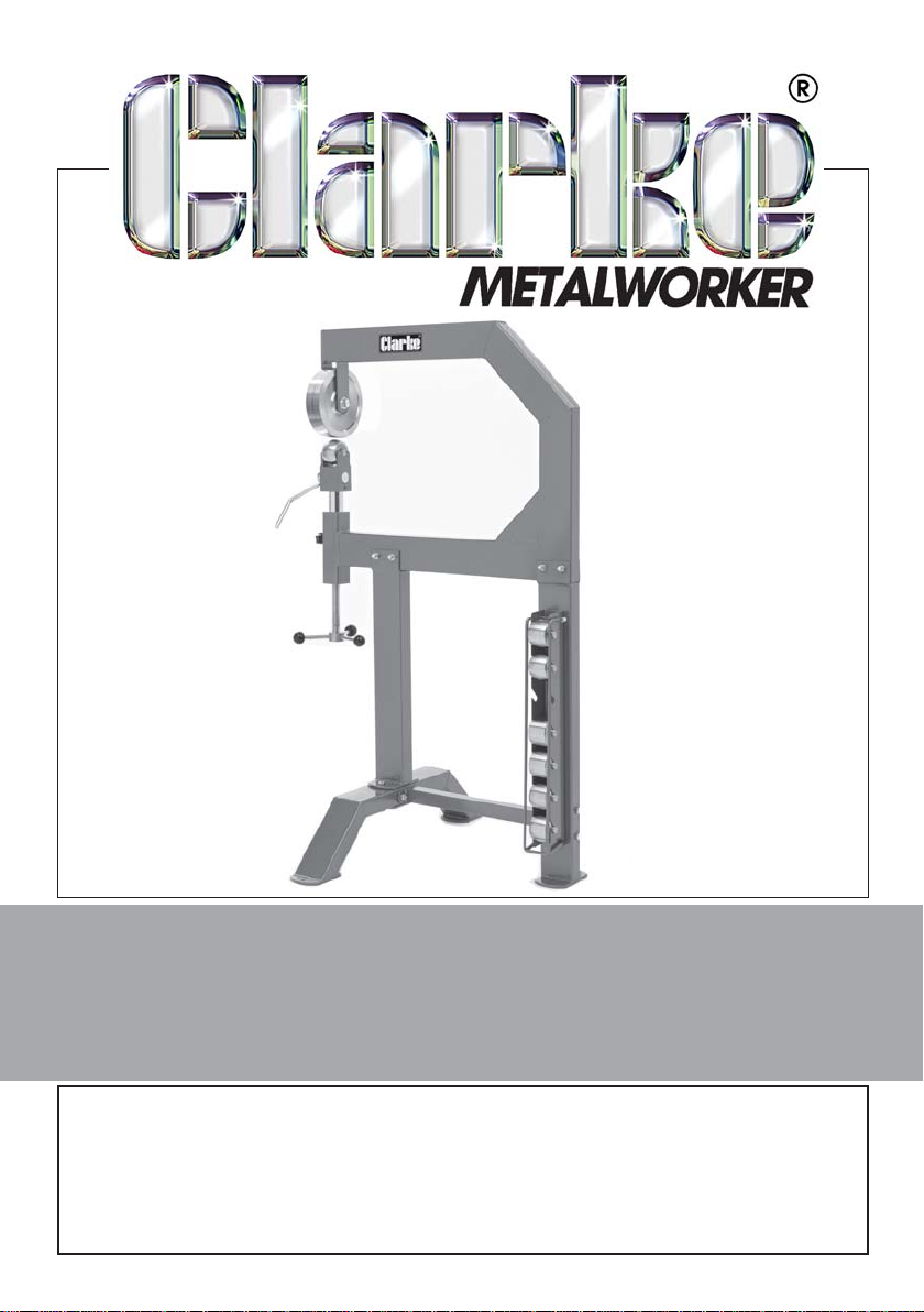
ENGLISH WHEEL
Model No. EW-705
P ART NO: 7627900
OPERATING & ASSEMBLY
INSTRUCTIONS
GC004/12
Page 2
INTRODUCTION
Thank you for purchasing this CLARKE English Wheel.
The EW705 is suitable for forming and shping light gauge steel and aluminium
panels and for removing dents, smoothing hammer marks, flattening welds
etc. Pressure is applied by adjusting the lower anvil roller. Standard anvil rollers
are supplied as listed in the specification.
Before attempting to use this product, please read this manual thoroughly
and follow the instructions carefully. In doing so you will ensure the safety of
yourself and that of others around you, and you can look forward to your
purchase giving you long and satisfactory service.
GUARANTEE
This product is guaranteed against faulty manufacture for a period of 12
months from the date of purchase. Please keep your receipt which will be
required as proof of purchase.
This guarantee is invalid if the product is found to have been abused or
tampered with in any way, or not used for its intended purpose.
Faulty goods should be returned to their place of purchase, no product can
be returned to us without prior permission. This guarantee does not effect
your statutory rights.
TABLE OF CONTENTS
INTRODUCTION .................................................................................. 2
GUARANTEE ........................................................................................ 2
GENERAL SAFETY RULES .....................................................................3
OVERVIEW .......................................................................................... 4
ASSEMBLY ........................................................................................... 5
BEFORE STARTING WORK ...................................................................8
OPERATION .........................................................................................9
MAINTENANCE ...................................................................................9
SPECIFICATION ...................................................................................10
COMPONENT PARTS LIST ....................................................................11
2
Parts & Service: 020 8988 7400/E-mail:[email protected] or [email protected]
Page 3
GENERAL SAFETY RULES
WORK AREA
1. Keep the work area clean and well lit. Cluttered and dark areas invite
accidents.
2. Keep children and bystanders away while operating this tool. Distractions
can cause you to lose control.
PERSONAL SAFETY
1. Stay alert, watch what you are doing and use common sense when you
are using this equipment. Do not operate this tool when you are tired, ill or
under the influence of alcohol, drugs or medication.
2. Safety equipment such as gloves and non-skid shoes used for appropriate
conditions will reduce personal injuries.
3. Do not over-reach. Keep your proper footing and balance at all times.
4. Concentrate on the job in hand, no matter how trivial it may seem. Be
aware that accidents are caused by carelessness due to familiarity.
5. Do not wear loose clothing or jewellery which may get caught in moving
parts. Wear protective hair covering to contain long hair. For best footing,
wear rubber soled footwear. Keep floor clear of oil, scrap wood, etc.
6. Keep equipment clean for the best and safest performance. Check for
misalignment or binding of moving parts, broken parts, or any condition
that may affect the tool’s operation. If damaged, have the tool repaired
before use.
7. Always hold the workpiece securely. Large workpieces should always be
well supported to avoid loss of control.
8. Secure the English Wheel frame to the floor to prevent it from moving or
tipping over in use.
9. Sheet metal may have sharp edges. Always wear gloves when handling
sheet metal and use caution when bending and cutting.
10. Rollers are heavy, take care when handling.
SERVICING
1. When necessary, have equipment repaired by a qualified person using
identical replacement parts. This will ensure that the safety of the tool is
maintained.
Please keep these instructions in a safe place for future reference.
3
Parts & Service: 020 8988 7400/E-mail:[email protected] or [email protected]
Page 4
OVERVIEW
The following main components are supplied loose, accompanied by a
fixings pack containing nuts, bolts, washers, handle balls, handle arms and
locking knob.
• Upper Frame (1) • Upper Roller (2)
• Front Upright (16) • Lower Anvil Rollers (11) with spindles
• Rear Upright (17) • Roller Support Yoke (8)
• Link Beam (19) • Support Tube (5)
• Front Legs (15) • Adjusting Rod (14)
• Backing Plate(18) • Eccentric Shaft & Handle (6/7)
• Roller Storage Rack (13) & Locking Bar (12)
4
Parts & Service: 020 8988 7400/E-mail:[email protected] or [email protected]
Page 5
ASSEMBLY
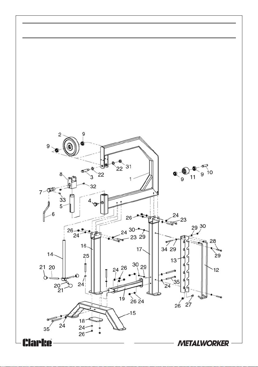
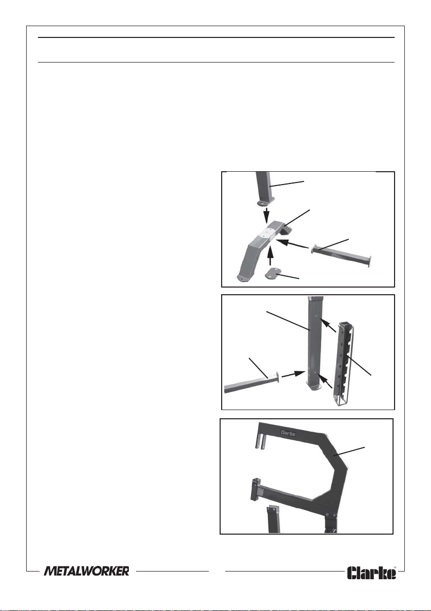
This EW-705 components are shown below.
1. Unpack the components on the floor where the unit will be installed.
• When unpacking, check for damage or shortages etc. Any found should
be reported to your CLARKE dealer where the product was originally
purchased.
• Assemble all the frame components loosely to ensure all bolt holes will line
up, then tighten everything securely when the assembly is complete.
2. Assemble the front upright (16) to
the front legs (15), with the
backing plate (18), 85 mm bolts
(25), nuts (26) & washers (24).
3. Next connect the link beam (19) to
the front legs with two 130 mm
bolts (35), washer (24) and nuts
(26).
Upright(16)
Front Legs(15)
Link Beam(19)
Backing
Plate(18)
4. Attach the link beam (19) to the
rear upright (17) with two 130 mm
bolts (35), nuts (26) & washers (24).
5. Bolt the anvil roller storage rack
(13) to the rear upright (17) using
two 65 mm bolts (28), washers (29)
and nuts (30).
6. With the help of an assistant, lift
the upper frame (1) into position
on the front and rear legs and
secure with the 80 mm bolts (23),
nuts (26) & washers (24). Tighten
all nuts & bolts securely.
Parts & Service: 020 8988 7400/E-mail:[email protected] or [email protected]
Rear Upright(17)
Link
Beam(19)
Storage
Rack(13)
Upper
Frame(1)
5
Page 6
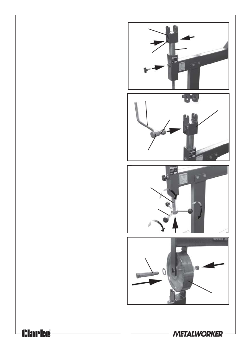
7. Lower the roller yoke assembly
into the mounting hole in the
frame.
8. Screw the locking knob (4) into
the threaded hole on the upper
frame (1). Lift and turn the support
tube (5) assembly so that the
locking knob (4) seats into the slot
in the support tube. Tighten the
knob.
9. Insert the eccentric shaft (7) with
its handle (6) into the hole in the
yoke (8).
11. Thread each handle lever (20)
into the adjusting rod (14) and
securely tighten.
12. Offer the adjusting rod (14) into
the under side of the frame (1)
and screw it into the support tube
already in position.
13. Take the upper roller (2) and
position it within the bracket of
the upper frame (1). Pass the axle
(3) through the assembly and
secure with two washers (22) and
nut (31).
• Note that a 24mm socket will be
required for the nut and a 17mm
open spanner for the end of the
axle.
16. Slide the spindle into each of the
anvil rollers and store the rollers
on the roller storage rack (13).
• Place them in order of size on the
rack. (Each roller has the size
stamped on it).
Roller
Yoke(8)
Grub
screws(32)
Locking
Knob(4)
Handle(6)
Eccentric
Shaft(7)
Grub screw(33)
Adjusting
Rod (14)
Lever (20)
Axle(3)
Support
Tube(5)
Yoke(8)
Upper Roller(2)
6
Parts & Service: 020 8988 7400/E-mail:[email protected] or [email protected]
Page 7

MOUNTING THE FRAME TO THE FLOOR
The foot of each leg has a bolt hole which allows the English Wheel to be
fixed to a suitably level floor.
With the help of at least one other person, move the assembled unit to the
chosen location where it will be mounted.
Measure the size of the mounting holes in the front leg and back stands, then
drill appropriate sized holes to accommodate the mounting bolts or screws
(fixings not supplied).
7
Parts & Service: 020 8988 7400/E-mail:[email protected] or [email protected]
Page 8
BEFORE STARTING WORK
CAUTION! METAL EDGES CAN BE VERY SHARP. AVOID INJURIES BY
WEARING APPROVED SAFETY GLOVES
Check that all component parts are secure and that the rollers turn freely.
Practice on some scrap metal before attempting work on the actual stock
workpiece. Using an English Wheel successfully requires a considerable
degree of acquired skill and experience.
The English Wheel can be used with rollers of various radii in order to suit the
task to be carried out. These various radii allow different curves to be formed
in the workpiece.
SELECTING THE LOWER ANVIL ROLLER
1. Select the appropriate lower anvil roller from the storage rack and place it
with its spindle on the roller yoke. When selecting the roller, consider the
type and hardness of the metal being formed as well as the desired
curvature of the metal.
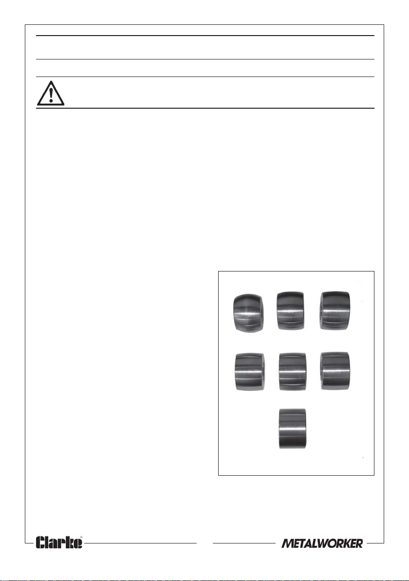
• All the rollers have the same
diameter (75 mm) and the same
width (50.8 mm), but as can be
seen from the picture, the working
surface radii are different.
Note that these are always
expressed in imperial units.
• The flat roller is used for smoothing,
as against forming curved profiles.
• Smaller radius rollers produce a
tighter curve on the workpiece than
the larger radius rollers. It is also
common practice to change rollers
during operation in order to
achieve a specific profile.
2” 3” 4”
6” 8” 10”
FLAT
Dimension indicated is the radius
8
Parts & Service: 020 8988 7400/E-mail:[email protected] or [email protected]
Page 9
OPERATION
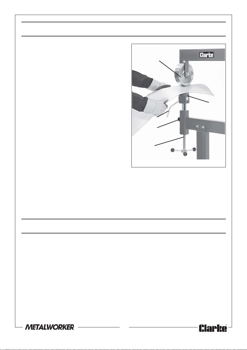
1. Insert the sheet metal workpiece
between the upper and lower anvil
rollers.
2. With the eccentric shaft handle in
the horizontal (slack) position, turn
the adjusting rod to raise the anvil
roller yoke and gently pinch the
workpiece.
Minor adjustments to the gap
between the rollers can be made
by moving the eccentric shaft up or
down.
• Pinching it tightly will make it harder
to pass the metal through the rollers
and may cause unwanted
creasing.
• Pinching it loosely makes work
easier and therefore more
accurate. However, it may take
more passes to form the required shape.
3. Before working, turn the locking knob clockwise until tight.
4. Begin forming the metal by pushing and pulling it through the rollers.
5. If minor adjustments are required between the rollers, loosen the handle.
This causes the eccentric shaft to slightly raise or lower the anvil roller.
Upper Roller
Handle
Locking
Knob
Adjusting
rod
Anvil Roller
Yoke
MAINTENANCE
Always inspect the wheel and anvil rollers before use and ensure they are in
top condition. Check that all moving parts do so smoothly and freely.
After use, keep the rollers clean and occasionally lubricate moving parts with
a light oil. This will also inhibit any corrosion of the metal components.
For any technical problems contact your CLARKE International Service
Department on 020-8988-7400.
9
Parts & Service: 020 8988 7400/E-mail:[email protected] or [email protected]
Page 10
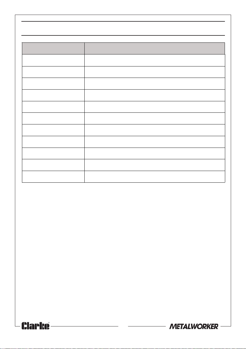
SPECIFICATION
metI noitacificepS
thgieWgk3.26
)HxDxW(snoisnemiDmm8051x068x359
yticapaCtaorhT )ecafrusleehwfoertnecmorfderusaem
snoisnemiDrelloRlivnA
suidaR"2)mm(suidar05xediw8.05xaid57
suidaR"3)mm(suidar57xediw8.05xaid57
s
uidaR"4)mm(suidar001xediw8.05xaid57
suidaR"6)mm(suidar051xediw8.05xaid57
suidaR"8)mm(suidar302xediw8.05xai
suidaR"01)mm(suidar452xediw8.05xaid57
eliforPtalF)mm(suidar0xediw8.05xaid57
d57
()"82(mm507
Please note that the details and specifications contained herein, are correct
at the time of going to print. However, CLARKE International reserve the right
to change specifications at any time without prior notice.
10
Parts & Service: 020 8988 7400/E-mail:[email protected] or [email protected]
Page 11
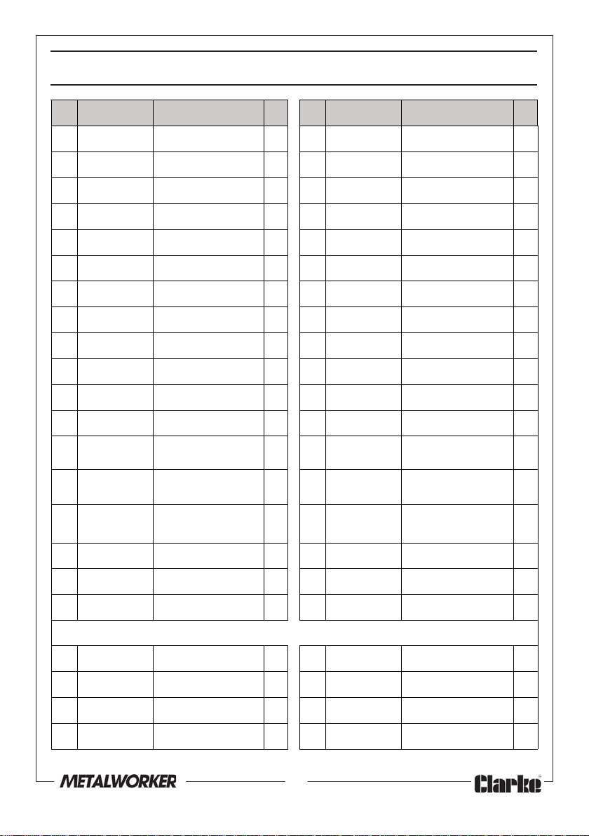
COMPONENT PARTS LIST
oN oNtraP noitpircseD ytQ oN oNtraP noitpircseD ytQ
110507WEMSemarFreppU19191507WEMSmaeBkniL1
220507WEMSrelloRreppU10202507WEMSreveLeldnaH3
330507WEMStfahSrelloRreppU11212
440507WEMSbonKgnikcoL12222507WEMSmm02rehsaW2
550507WEMSebuTtroppuS13232507WEMSmm08x01M,tloB4
660507WEM
SeldnaH14242507WEMSmm01,rehsaW02
770507WEMStfahScirtneccE15252507WEMSmm58x01M,tloB2
880507WEMSekoYrelloR16262507WEMS01M,tu
990507WEMSZZ-4005gniraeB617272507WEMSmm51x01M,tloB1
0101507WEMSeldnipSrelloR78282507WEMSmm56x8M,tloB2
1111507WEMS**re
2121507WEMStekcarBgniniateR10303507WEMS8M,tuN3
3131507WEMS
4141507WEMSdoRgnitsujdA12323507WEMS
5151507WEMSsgeLtnorF13333507WEMS
6161507WEMSthgirpUtnorF14343507WEMSmm59x8M,tloB1
7171507WEMSthgirpUraeR15353507WEMSmm031x01M,tloB4
lloRlivnA19292507WEMSmm8,rehsaW6
relloRlivnA
kcaRegarotS
11313
507WEMSeldnaHllaB3
N11
507WEMS61M,tuN1
wercsburG
mm21x8M
,wercsburG
x01M
mm61
2
1
8181507WEMSetal
** yllaudividnielbaliavaeradnasezisgniwollofehtnideilppuserasrellorlivnA
a1163507WEMSdar"2relloRl
b1173507WEMSdar"3relloRlivnA1e1114507WEMSdar"01relloRlivnA1
c1183507WEMSdar"4rello
d1193507WEMSdar"6relloRlivnA1
Parts & Service: 020 8988 7400/E-mail:[email protected] or [email protected]
PgnikcaB1
ivnA1d1104507WEMSdar"8relloRlivnA1
RlivnA1f1124507WEMS)talf(relloRlivnA1
11
Page 12
 Loading...