

Page 1
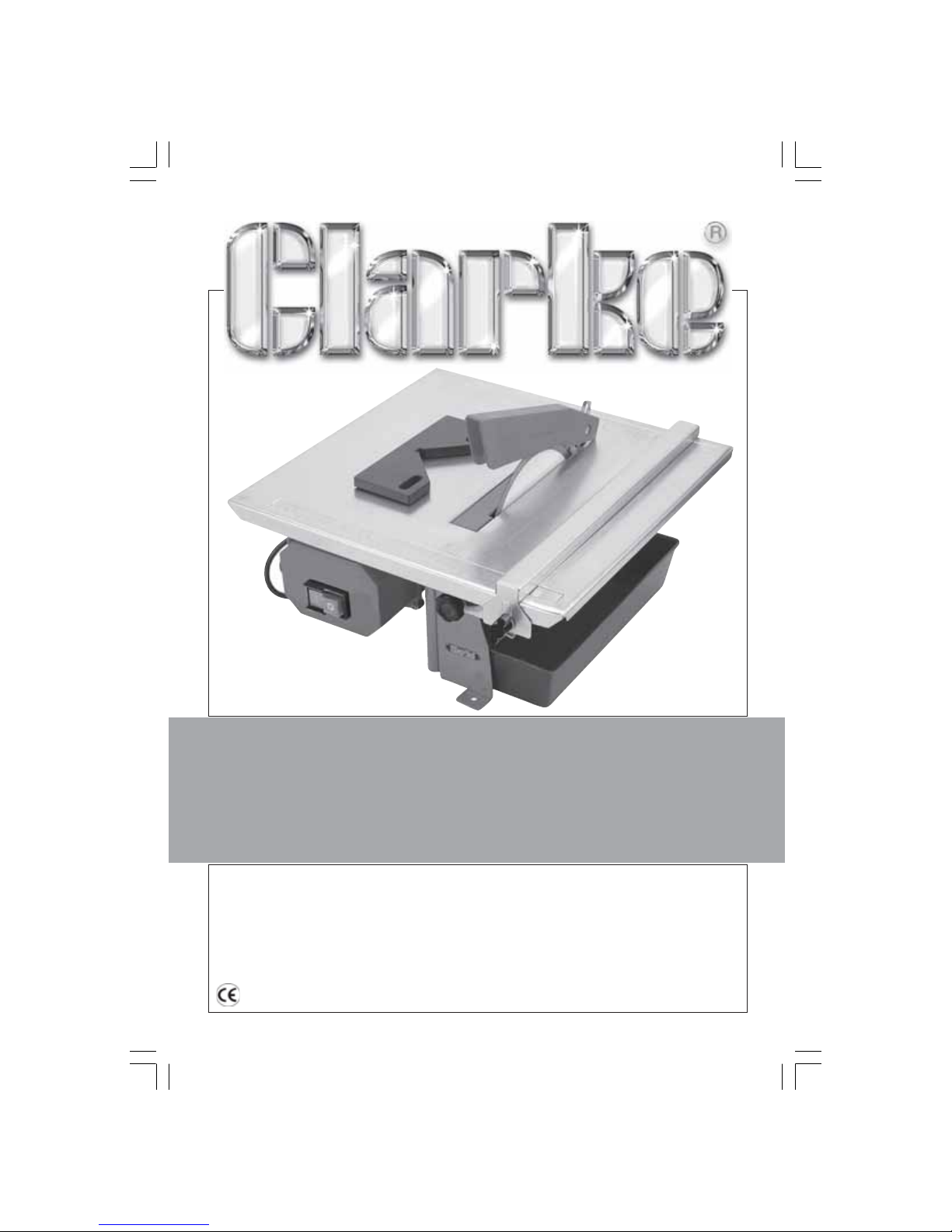
ELECTRIC TILE CUTTER
Model No. ETC6
Part No. 3400500
OPERATING & MAINTENANCE
INSTRUCTIONS
0305
ELECTRIC TILE CUTTER
Page 2
Thank you for purchasing this Clarke Tile Cutting Machine.
The ETC6 tile cutter incorporates a 180mm sintered diamond cutting disk and
will make straight cuts on tiles with a maximum cutting depth of 38mm.
The table may be tilted so that tiles may be cut to any angle up to 45 degrees.
The maximum cutting depth at 45 degrees is 20mm.
Please read this manual thoroughly before use. This will ensure the safety of both
yourself and those around you, and will also ensure long and trouble free
service from your Tile Cutter.
GUARANTEE
This product is guaranteed against faults in manufacture for 12 months from
purchase date. Please keep your receipt as proof of purchase.
This guarantee is invalid if the product has been abused or tampered with in
any way, or not used for the purpose for which it is intended. The reason for
return must be clearly stated.
This guarantee does not affect your statutory rights.
SPECIFICATIONS
Motor ....................................................................................... 230V, 50 Hz 1ph
Power Rating .......................................................................... 450Watts
Running Current ..................................................................... 1.9Amps
Speed (No load) .................................................................... 2990RPM
Fuse Rating .............................................................................. 13 Amps
Table Dimensions .................................................................... 385x380mm
Weight (Net) ........................................................................... 9.2kg
Cutting Angle ......................................................................... 0 - 45 degrees
Cutting Depth at 90O............................................................. 38mm
Cutting Depth at 45
O
............................................................. 20mm
Cutting Disk Diameter ............................................................ 180mm
Cutting Disk Bore .................................................................... 22mm
Cutting Disk Part Number ...................................................... 6490640
Sound Power Level ................................................................. 100 Lw(A)
Sound Pressure Level ............................................................. 87dB(A)
Vibration .................................................................................. <2.5m/s
2
Overall Dimensions (LxWxH) .................................................. 385x385x220mm
Duty Cycle .............................................................................. S3 40%**
Part Number ........................................................................... 3400500
** Duty cycle - 4mins ON followed by 6mins OFF in any 10 minute period
1
Page 3

Common sense applies to the use of both this and any other electric power tool.
In particular we bring the following points to your attention.
ALWAYS keep the work area clean, well lit and uncluttered.
ALWAYS place the machine on a firm steady base and at a comfortable
working height.
Apart from the water trough which is provided to wet the cutting disk,
ALWAYS check to ensure that all other parts of the machine and the
surrounding work area are kept dry.
ALWAYS use in a well ventilated area. Never operate the saw in the presence
of inflammable vapours.
ALWAYS keep children well clear of the work area at all times.
ALWAYS examine the cutting disk before use and replace if worn.
ALWAYS allow the motor freedom, so that the cutting disk will be cutting at, or
close to its maximum speed.
ALWAYS use Clarke general purpose safety goggles to protect the eyes from
flying particles.
ALWAYS take suitable precautions in respect of loose clothing, long hair and
jewellery, as these are potential hazards which could get caught up in the
moving parts of this high speed machine.
ALWAYS use a Clarke face mask to prevent inhalation of any dust which may
be produced.
ALWAYS disconnect from the power supply before making any adjustments to
the machine.
The use of work gloves is recommended, providing these allow you to retain
sufficient feel and sensitivity whilst operating the machine.
NEVER force the cutting disk if it is reluctant to cut properly or tends to slow down.
NEVER use this machine for cutting metal or vegetable matter. This machine
is for cutting stone, ceramics, marble and similar hard material ONLY.
NEVER attempt to repair the mains cable. If it, or any part of the switch assembly
becomes damaged, then it must be replaced.
NEVER apply side thrust to the cutting disk. i.e. try to cut on one side of the
disk only.
NEVER operate this machine with the Disk Guard removed.
7
DO NOT exceed the Duty Cycle - See Specifications
GENERAL SAFETY PRECAUTIONS
7
7
7
4
4
4
4
4
4
4
4
4
4
4
4
7
7
2
Page 4

WARNING!
If the power cable is worn or cut, or damaged in any way, have it
replaced immediately to avoid shock or fire hazard.
Connect the mains lead to a 230 volt (50Hz) domestic electrical supply via a standard 13
amp BS 1363 plug fitted with a 13 amp fuse, or a suitably fused isolator switch.
WARNING! THIS APPLIANCE MUST BE EARTHED.
IMPORTANT: The wires in the mains lead are coloured in accordance with the following code:
Green & Yellow - Earth
Blue - Neutral
Brown - Live
As the colours of the flexible cord of this appliance may not correspond with the coloured
markings identifying terminals in your plug, proceed as follows:
• Connect GREEN & YELLOW coloured cord to plug terminal marked with a letter ‘E’ or
Earth symbol “ ”, or coloured GREEN or GREEN & YELLOW.
• Connect BROWN coloured cord to plug terminal marked letter ‘L’ or coloured RED.
• Connect BLUE coloured cord to plug terminal marked letter ‘N’ or coloured BLACK.
We strongly recommend that this unit is connected to the mains supply via a
Residual Current Device (RCD).
I
MPORTANT!
If this appliance is fitted with a plug which is moulded onto the electric cable (i.e.
non- re-wireable) please note:
1. The plug must be thrown away if it is cut from the electric cable. There is a
danger of electric shock if it is subsequently inserted into a socket outlet.
2. Never use the plug without the fuse cover fitted.
3. Should you wish to replace a detachable fuse carrier, ensure that the correct
replacement is used (as indicated by marking or colour code).
4. Replacement fuse covers can be obtained from your local dealer or most
electrical stockists.
Fuse Rating
The fuse in the plug must be replaced with one of the same rating (13 amps) and this
replacement must be ASTA approved to BS1362.
Extension Cable
If an extension lead is needed, ensure the conductors have a diameter at least equal to
that of the cable fitted to the machine. Always unwind the extension cable fully before
use.
ELECTRICAL CONNECTIONS.
3
Page 5

1. With the machine disconnected from the mains supply, measure the tile or
piece of material to be cut and proceed to adjust:
A. The angle of the table - which can be adjusted 0° to 45° for mitre edge
cuts if required.
NOTE:
If bevel cuts are made with the larger portion of the tile on the right side of the cutting disk,
i.e. on the ‘downward’ slope side of the disk, there may be too little room for the parallel
fence. This operation must therefore be carried out freehand. DO NOT exert side pressure
on the cutting disk.
B. The position of the fence on the table top. To ensure accurate cuts, check
the alignment of the fence by refering to the built in calibrations which
are set into each end of the table top.
Retighten all locking knobs securely to ensure secure positions for both the
table and the fence.
2. Fill the water trough located underneath the table with just sufficient water so
that the edge of the cutting disk can be kept constantly wet. Do not overfill
as this can cause an unnecessary mess. Check the water level constantly
during use and top up as necessary.
3. Start the machine by pressing the green button on the switch panel, marked ‘I’.
4. Holding the material firmly at all times against the parallel fence, or held in
the mitre gauge as required, move it steadily over the table, into the cutting
edge of the disk...WITH THE GLAZED SIDE OF THE TILE FACING UP.
DO NOT force the tile through the disk. Keep the speed of the disk as near to
its maximum speed as possible.
Always cut in a straight line and DO NOT attempt to cut a curved line.
Keep hands well clear of the disk whilst it is in motion. Remove all pieces using
a piece of wood, or similar, before making the next cut.
5. To stop the machine at any time, press the red button on the switch panel
marked ‘O’.
Always do this as soon as cutting has been completed, so as not to exceed
the Duty Cycle (see Specifications) and before making any adjustments to
the machine.
NOTE:
In order to get the feel of the machine and reduce the possibility of wastage, we recommend
that trial cuts are made first with surplus or scrap material of a similar type to that to be cut.
OPERATION
INSTALLATION
Provision is made so that the Tile Cutter may be semi-permanently fixed to a workbench
or table, using suitable bolts in the two holes in the base of the machine.
If a permanent location is not feasible or desirable, always ensure its temporary
location is flat and even and at a convenient height with adequate light.
4
Page 6
1. Ensure that the machine is switched off and disconnected from the mains.
2. First remove the water trough, then remove the two screws securing the
cutting disk cover, beneath the table, and withdraw the cover.
3. The drive shaft has two flats milled on its end, allowing a spanner (supplied) to
be used to hold the shaft whilst undoing the disk securing nut, again using the
spanner supplied.
Pull off the Disk Flange, followed by the disk.
4. Take this opportunity to clean the drive-shaft of any foreign matter.
5. Replace the cutting disk ensuring the direction of rotation is correct. If in
doubt, take note that the shaft rotates in an anticlockwise direction, as you
look directly at it. The disk must be fitted so that the arrow, on the blade,
points in the SAME direction.
6. Replace the disk flange and screw on the nut, which should then be ‘nipped
up’. DO NOT overtighten.
7. Replace the disk cover.
CHANGING THE CUTTING DISK
MAINTENANCE
When carrying out servicing or maintenance tasks...ALWAYS disconnect the
machine from the mains supply.
Always rotate the cutting disk by hand before use to check for cracks or distortion.
If any damage is detected, renew the disk.
Check the power cable to ensure it is in perfect condition.
Drain the water tank after use and ensure it is dry before storing.
ALWAYS maintain the machine in top condition. When not in use, keep it covered,
and store in a dry place, not exposed to the elements.
DECLARATION OF CONFORMITY
We declare that this product conforms to the following standards/directives
89/392/CEE, modified by 98/68/CEE (Machinery Directive)
93/68/CEE modified by EN61029-1 (LVD)
98/336/CEE modified by 93/68/CEE (EMC)
5
Page 7
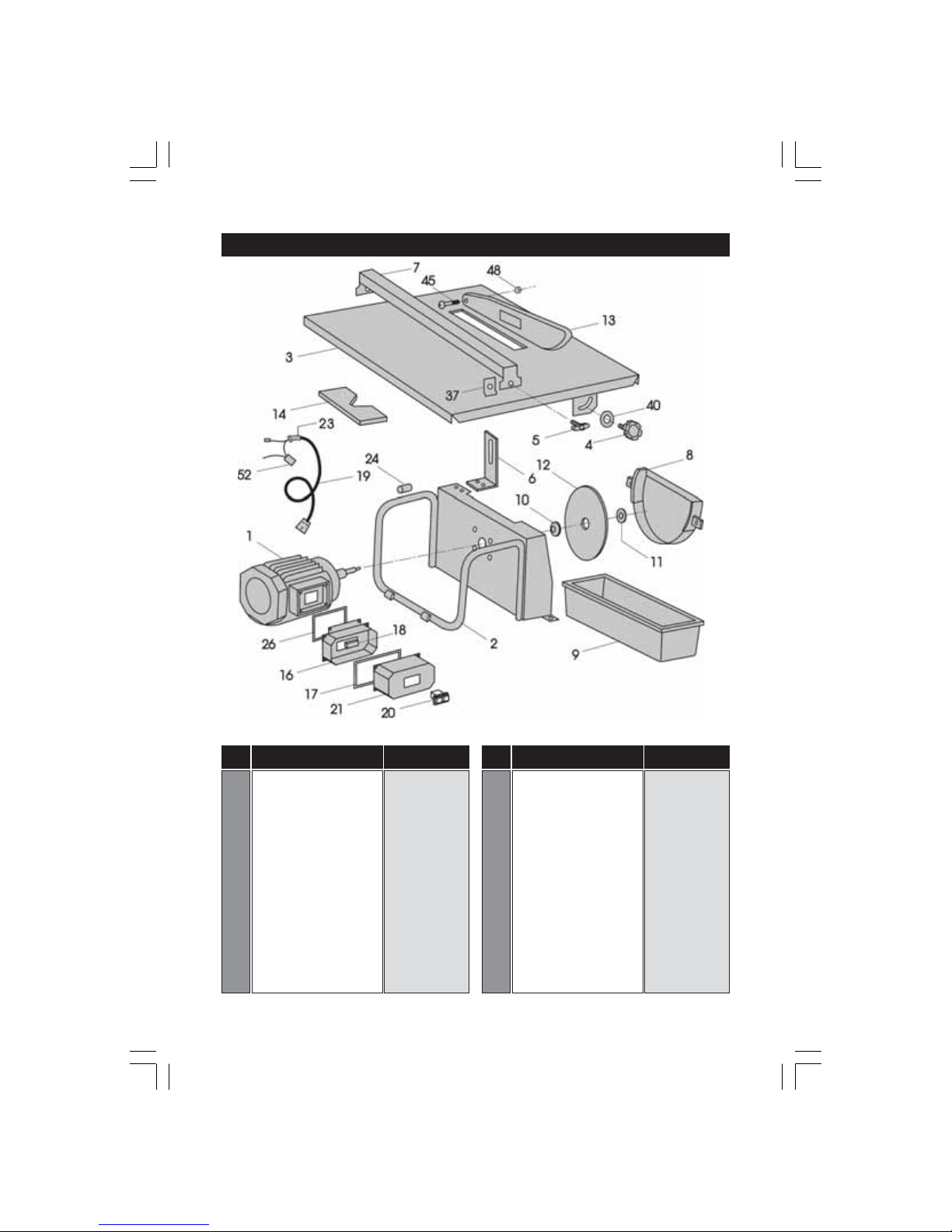
PARTS LIST AND DIAGRAM
No. Description Part No.
1 Motor Complete RWETC601
2 Tubular Frame RWETC602
3 Table RWETC603
4 Tile Guide Knob RWETC604
5 Table Adjuster Knob RWETC605
6 Blade Guard Support RWETC606
7 Tile Guide RWETC607
8 Lower Blade Guard RWETC608
9 Water Tank RWETC609
10 Inner Flange RWETC610
11 Outer Flange RWETC611
12 Cutting Disc 6490640
13 Upper Blade Guard RWETC613
14 Tile Angle Guide RWETC614
No. Description Part No.
16 Switch Box (Inner) RWETC616
17 Gasket RWETC617
18 Capacitor RWETC618
19 Cable loom RWETC619
20 Switch RWETC620
21 Switch Box (Outer) RWETC621
23 Cable Grommet RWETC623
24 Plastic Bushing RWETC624
26 Gasket RWETC625
37 Clamp Plate RWETC637
40 Flat Washer RWETC640
45 Screw RWETC645
48 Self Locking Nut RWETC648
52 Thermal Capacitor RWETC652
6
 Loading...