

Page 1
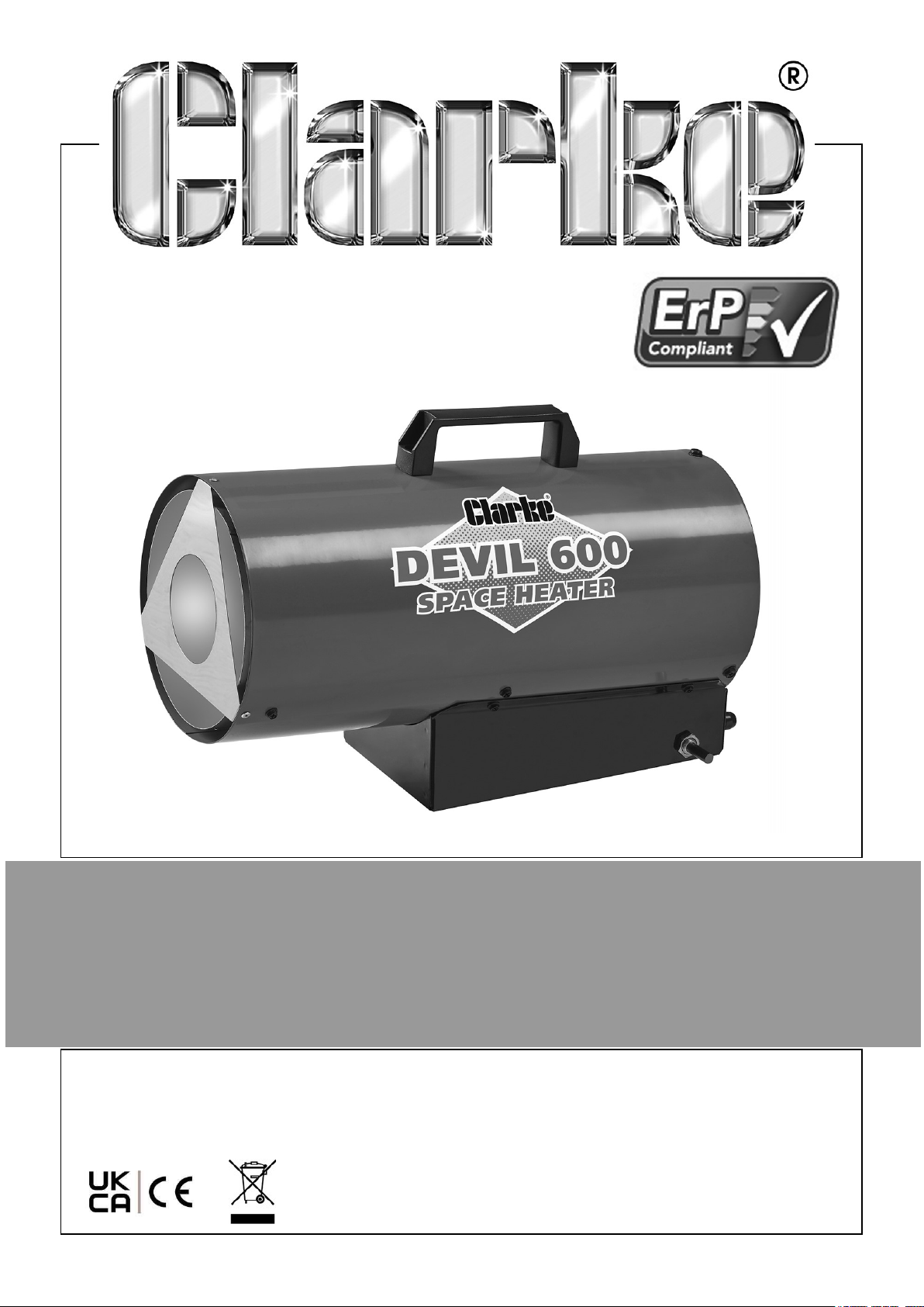
GAS HEATER
MODEL NO: DEVIL 600
PART NO: 6950023
USER INSTRUCTIONS
ORIGINAL INSTRUCTIONS DL0525
Page 2
INTRODUCTION
Thank you for purchasing this CLARKE Gas Powered Heater.
Before attempting to use this product, please read this manual thoroughly and follow
the instructions carefully. In doing so you will ensure the safety of yourself and that of
others around you, and you can look forward to your purchase giving you long and
satisfactory service.
GUARANTEE
This product is guaranteed against faulty manufacture for a period of 12 months from
the date of purchase. Please keep your receipt which will be required as proof of
purchase.
This guarantee is invalid if the product is found to have been abused or tampered
with in any way, or not used for the purpose for which it was intended.
Faulty goods should be returned to their place of purchase, no product can be
returned to us without prior permission.
This guarantee does not effect your statutory rights.
ENVIRONMENTAL RECYCLING POLICY
Through purchase of this product, the customer is taking on the obligation
to deal with the WEEE in accordance with the WEEE regulations in relation
to the treatment, recycling & recovery and environmentally sound disposal
of the WEEE.
In effect, this means that this product must not be disposed of with general
household waste. It must be disposed of according to the laws governing Waste
Electrical and Electronic Equipment (WEEE) at a recognised disposal facility.
2
Parts & Service: 020 8988 7400 / E-mail: [email protected] or [email protected]
Page 3
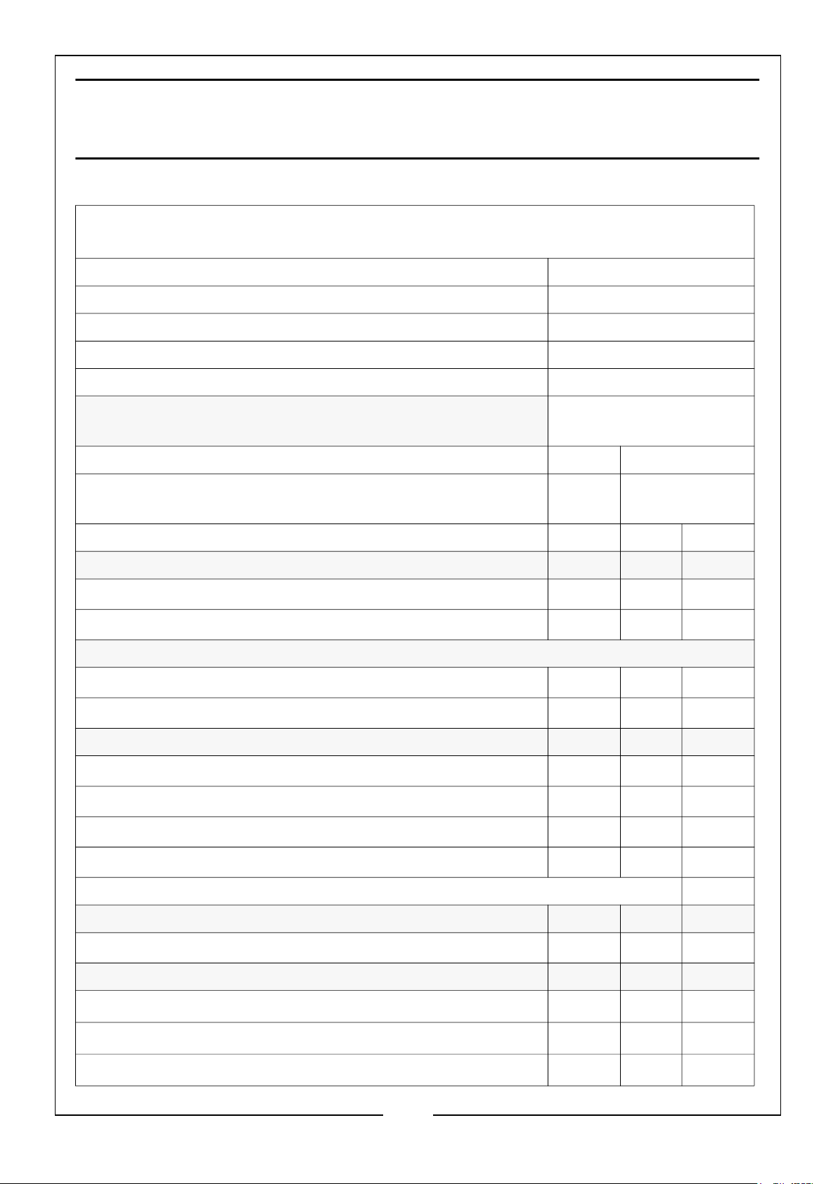
THE FOLLOWING TABLE ADDRESSES THE
INFORMATION REQUIREMENTS OF REG.2015/1188
Contact Details: Clarke International Ltd, Hemnall St, Epping, Essex, CM16 4LG
Tel: 0208 988 7400 Web: www.clarkeinternational.com
Model Number DEVIL 600
Indirect Heating Functionality No
Direct Heat Output 15kW
Indirect Heat Output N/A
Minimum permissible total flue length (vertical + horizontal) N/A
Fuel Nitrogen oxides (NOx)
Emissions
Value Unit
Select Fuel Type: Gaseous (Propane) 90 mg/kWh
input
(GCV)
Item Symbol Value Unit
Heat output
Nominal heat output P
Minimum heat output P
nom
min
15 kW
N/A kW
Auxiliary electricity consumption
At nominal heat output el
At minimum heat output el
max
min
0.0 kW
N/A kW
Power consumption
In off mode P
In standby mode P
In idle mode P
In networked standby mode P
0
sm
idle
nsm
0.00 W
0.00 W
N/A W
N/A W
Standby mode with display of information or status No
Permanent pilot flame power requirement
Pilot flame power requirement (if applicable) P
pilot
N/A kW
Efficiency (NCV)
Useful efficiency at nominal heat output
Useful efficiency at minimum heat output
Seasonal space heating energy efficiency
n
th,nom
n
th, min
n
s
100.0 %
N/A %
75.0 %
3
Parts & Service: 020 8988 7400 / E-mail: [email protected] or [email protected]
Page 4
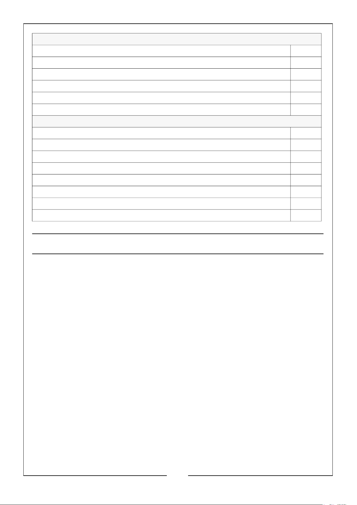
Type of heat output/room temperature control (select one)
Single stage heat output, no temperature control Yes
Two or more manual stages, no temperature control No
With mechanical thermostat temp control No
With electronic temperature control No
Electronic temperature control with day timer No
Electronic temperature control with week timer No
Other control options (multiple selections possible)
Room temperature control with presence detection No
Room temperature control with open window detection No
Room temperature control with distance control option No
Room temperature control with adaptive start control No
Room temperature control with working time limitation No
Room temperature control with black bulb sensor No
Room temperature control with self-learning functionality No
Room temperature control with control accuracy No
FUNCTION AND OPERATING PARAMETERS
This is a gas powered heater. It’s intended use is for drying and the warming of
commercial/industrial buildings where adequate ventilation is provided.
• It must be operated as prescribed in the operating manual.
• It is not intended to be used for domestic use or for the heating of habitable
areas.
• It is not intended to be used to reach and maintain a certain level of human
thermal comfort within an enclosed space in which the heater is situated.
• It is not intended to be used in enclosed areas with restricted ventilation.
• It is not for use in areas with high levels of fluctuating drafts.
• DO NOT use for warming animals or live stock.
4
Parts & Service: 020 8988 7400 / E-mail: [email protected] or [email protected]
Page 5

SAFETY INFORMATION
Read, and make sure you fully understand the following precautions and the hazards
associated with this type of equipment.
1. ONLY use with the voltage specified and ensure the heater is properly earthed.
2. Use only the hose and factory preset regulator provided with the heater.
3. ONLY use propane gas, set up for vapour withdrawal.
4. Use only in well ventilated areas. Provide ventilation of at least 1.5ft2 (1400cm2)
opening of fresh outside air.
5. DO NOT use this heater in small rooms when they are occupied by persons not
capable of leaving the room on their own unless constant supervision is provided.
6. For indoor use only. DO NOT use heater outdoors.
7. DO NOT use this heater in the immediate surrounds of a bath, a shower or a
swimming pool
8. DO NOT use for the heating of habitable areas of domestic premises; for use in
public buildings, refer to national regulations.
9. DO NOT use the heater in a basement or below ground level. Propane gas is
heavier than air. If a leak occurs. propane gas will sink to the lowest possible level.
10. Keep the heater area clear and free from combustible materials, gasoline, paint
thinner and other flammable vapours and liquids. For minimum safe clearance
limits, see page 13.
11. DO NOT use heater in areas with high dust content. Dust is combustible.
12. DO NOT point the heater at the propane tank.
13. Keep propane tank(s) below 100oF (37.8oC).
14. Check the heater for damage before each use. DO NOT use if dropped. DO NOT
use a damaged heater.
15. Check the hose before each use of the heater. If highly worn or cut, replace with
hose specified by the manufacturer before using the heater.
16. Locate the heater on a stable and level surface if the heater is hot or operating.
17. Not intended for use on finished floors.
18. NEVER block the air inlet (rear) or air outlet (front) of the heater.
19. DO NOT cover the heater while in use.
20. Keep the heater away from strong drafts, water spray, rain or dripping water.
21. DO NOT leave the heater unattended.
22. NEVER move, handle or service a hot, operating or plugged-in heater.
5
Parts & Service: 020 8988 7400 / E-mail: [email protected] or [email protected]
Page 6
23. To prevent injury wear gloves when handling the heater.
24. NEVER attach duct work to front or rear of the heater.
25. DO NOT alter the heater. Keep the heater in its original state. If the heater has
been altered in any way, DO NOT use.
26. Turn off the propane supply and unplug the heater when not in use.
27. Use only original replacement parts. This heater must use design-specific parts.
Improper replacement parts could be highly dangerous.
28. DO NOT place torsional stress on any hoses or cables.
29. DO NOT use this heater with a programmer, timer, separate remote control
system or any other device that switches the heater on automatically, since a fire
risk exists if the heater is covered or positioned incorrectly.
30. This heater is only intended for use in industrial, commercial and building
industries, it is NOT to be used by children or persons with reduced physical,
sensory or mental capabilities, or lack of experience and knowledge.
31. Keep all children and animals away from the heater.
32. DO NOT use for warming animals or live stock.
33. Children should NOT play with the appliance.
34. BYSTANDERS: When the heater is to be operated in the presence of other
people the user is responsible for informing those present of the safety
precautions and of the hazards involved.
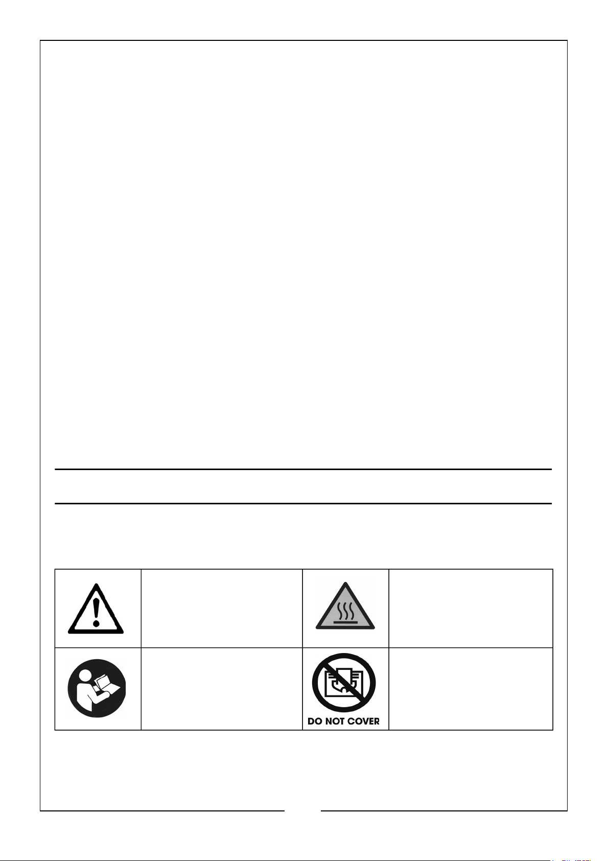
SAFETY SYMBOLS
Please read all of the safety and operating instructions carefully before using this
product. The following safety symbols may be found on the product.
GENERAL HAZARD
WARNING
HOT SURFACE, DO NOT
TOUCH
ALWAYS READ THIS
MANUAL BEFORE USE
6
Parts & Service: 020 8988 7400 / E-mail: [email protected] or [email protected]
DO NOT COVER
Page 7

GENERAL PRECAUTIONS
Even though this heater operates very close to 100 percent combustion efficiency, it
still produces small amounts of carbon monoxide.
• Carbon Monoxide (CO) is toxic.
• Pregnant women, persons with a heart or lung condition, anemia or under
the influence of alcohol, or those at high altitude, are more likely to be
effected by Carbon Monoxide.
• CO can build up in a confined space and failure to provide adequate
ventilation can be fatal.
The early symptoms of asphyxiation caused by inadequate ventilation are:
• headache • nausea
• dizziness • dry mouth or sore throat
Should anyone show these symptoms, they must GET FRESH AIR IMMEDIATELY.
Turn off the heater and have it serviced before using again.
Be sure to follow all warnings in this manual.
WE RECOMMEND THE USE OF A CARBON
MONOXIDE DETECTOR
7
Parts & Service: 020 8988 7400 / E-mail: [email protected] or [email protected]
Page 8
ELECTRICAL CONNECTIONS
Plug must be BS1363/A approved.
WARNING! Read these electrical safety instructions thoroughly
before connecting the product to the mains supply.
Before switching the product on, make sure that the voltage of your electricity supply
is the same as that indicated on the rating plate. This product is designed to operate
on 230VAC 50Hz. Connecting it to any other power source may cause damage.
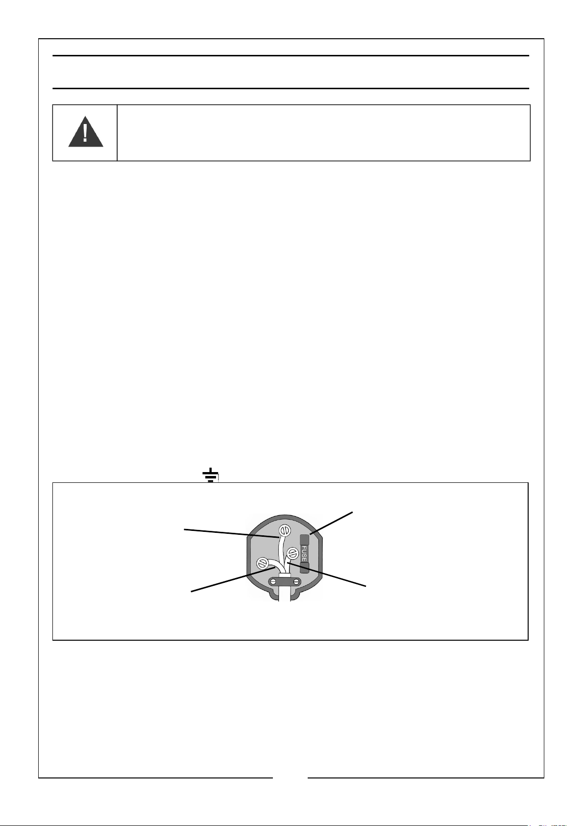
This product may be fitted with a non-rewireable plug. If it is necessary to change the
fuse in the plug, the fuse cover must be refitted. If the fuse cover becomes lost or
damaged, the plug must not be used until a suitable replacement is obtained.
If the plug has to be changed because it is not suitable for your socket, or due to
damage, it should be cut off and a replacement fitted, following the wiring
instructions shown below. The old plug must be disposed of safely, as insertion into a
mains socket could cause an electrical hazard.
If the colours of the wires in the power cable of this product do not correspond with
the markings on the terminals of your plug, proceed as follows.
• The wire which is coloured Blue must be connected to the terminal which is
marked N or coloured Black.
• The wire which is coloured Brown must be connected to the terminal which is
marked L or coloured Red.
• The wire which is coloured Yellow and Green must be connected to the terminal
which is marked E or or coloured Green.
Always fit a 7 Amp fuse.
Earth
(Green and Yellow)
Neutral
(Blue)
Ensure that the outer sheath of the cable is firmly held by the clamp
We strongly recommend that this machine is connected to the mains supply via a
Residual Current Device (RCD)
Live
(Brown)
If in any doubt, consult a qualified electrician. DO NOT attempt any repairs yourself.
Parts & Service: 020 8988 7400 / E-mail: [email protected] or [email protected]
8
Page 9
UNPACKING
When unpacking, check the heater for possible shipping damage. Should any damage
be apparent, please notify your CLARKE dealer immediately. Your heater is fully
assembled, only the electrical and gas supplies need connecting.
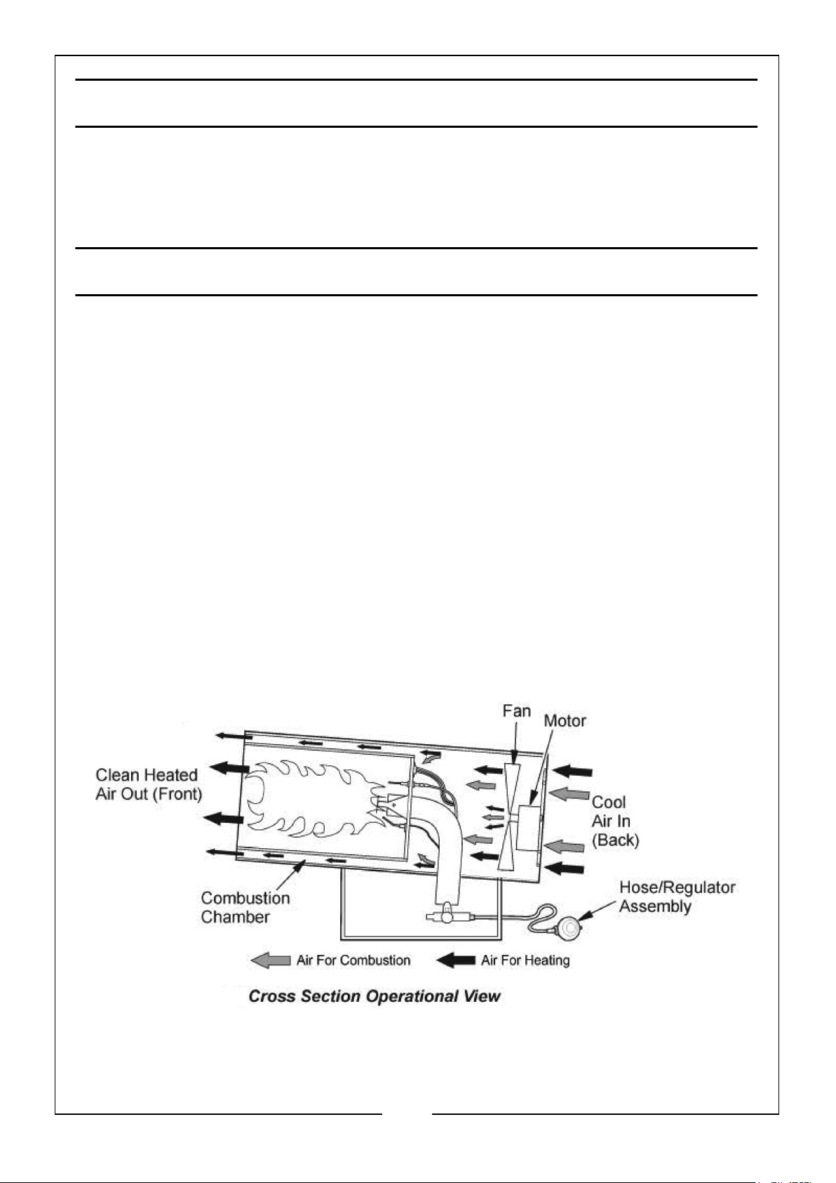
THEORY OF OPERATION
THE FUEL SYSTEM: The hose/regulator assembly attaches to the propane gas
supply. This provides fuel to the heater.
THE AIR SYSTEM: The motor turns the fan. The fan pushes air into and around the
combustion chamber. This air is heated and provides a stream of clean, hot air.
THE IGNITION SYSTEM: The Piezo igniter lights the burner.
THE AUTOMATIC CONTROL SYSTEM: Should the flame extinguish for any reason,
the thermocouple will quickly cool, causing the Flame Failure valve to close, shutting
off the gas supply.
Similarly, should there be a power failure, the safety shut off valve (solenoid) will shut
off the gas supply.
The machine is also fitted with a thermal overload protection, which will operate
should the unit overheat, shutting off the gas supply to the heater.
9
Parts & Service: 020 8988 7400 / E-mail: [email protected] or [email protected]
Page 10
PROPANE GAS SUPPLY
These heaters are designed for use with PROPANE GAS ONLY. Gas cylinders are
not supplied, but are readily available from builders merchants or gas suppliers etc.
As with all mechanical equipment, optimum performance will only be achieved if the
correct operation and servicing procedures are followed.
WARNING: PROPANE GAS CYLINDERS MUST BE USED AND STORED
IN ACCORDANCE WITH THE HIGHLY FLAMMABLE LIQUIDS AND
LIQUEFIED PETROLEUM GASES REGULATIONS 1972’
GAS CONNECTION
Connect the free end of the gas hose to the gas inlet connection on the heater and
tighten to ensure there are no gas leaks. Before attaching the regulator to the gas
cylinder, ensure the mating parts are free from grease and dirt and are undamaged.
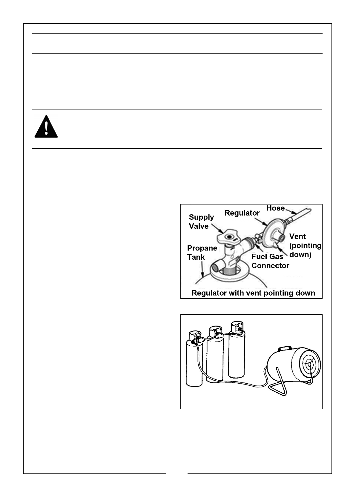
Fit the regulator to the cylinder,
tightening the thread as tight as possible
with a propane spanner, noting that the
threads are LEFT HANDED. To check for
leaks, use soapy water or liquid soap
applied to each of the connections. Any
bubbles formed indicate a leak. Correct
all leaks immediately.
IMPORTANT: The gas hose and
cylinder must ALWAYS be located
well behind the heater.
In order to reduce the risk of icing up
when operating at long periods at
maximum capacity, you should use a
larger capacity gas bottle, or two/three
bottles in parallel, as shown.
• The ‘Tee’ piece and ‘pigtails’ are
readily available from your
builders merchants or gas supplier.
CHANGING GAS BOTTLES
1. Turn off the heater and disconnect from the electrical supply.
2. Close the gas valve on the bottle and unscrew the regulator, (left hand thread).
3. Ensure the replacement bottle screw threads and gas orifice is perfectly clean
before screwing in the regulator valve tightly.
10
Parts & Service: 020 8988 7400 / E-mail: [email protected] or [email protected]
Page 11

4. Check to ensure there are no leaks using soapy water and when satisfied, plug in
to the electrical supply and restart the heater.
IN THE EVENT OF A GAS LEAK
1. Put out all smoking materials and other open flames.
2. DO NOT operate electric switches or light matches.
3. Close all supply valves on gas tank or cylinder.
4. DO NOT use your phone. USE a neighbour's phone or your mobile phone from
outside the building or wherever you detected the gas leak to call the fire service.
5. Immediately get everyone out of the building or area.
6. DO NOT re-enter the building, or area until a trained service person or the fire
service advises it is safe to return.
11
Parts & Service: 020 8988 7400 / E-mail: [email protected] or [email protected]
Page 12
INSTALLATION
WARNING: READ AND UNDERSTAND THE WARNINGS IN THE
SAFETY INFORMATION SECTION, PAGE 5. THEY ARE NEEDED TO
SAFELY OPERATE THIS HEATER. FOLLOW ALL LOCAL REGULATIONS
WHEN USING THIS HEATER.
WARNING: TEST ALL GAS PIPING AND CONNECTIONS FOR LEAKS
AFTER INSTALLATION OR SERVICING. NEVER USE AN OPEN FLAME
TO CHECK FOR A LEAK. APPLY A MIXTURE OF LIQUID SOAP AND
WATER TO ALL JOINTS. BUBBLES FORMING SHOW A LEAK.
CORRECT ALL LEAKS AT ONCE.
1. Provide a propane supply system (see Propane Gas Supply).
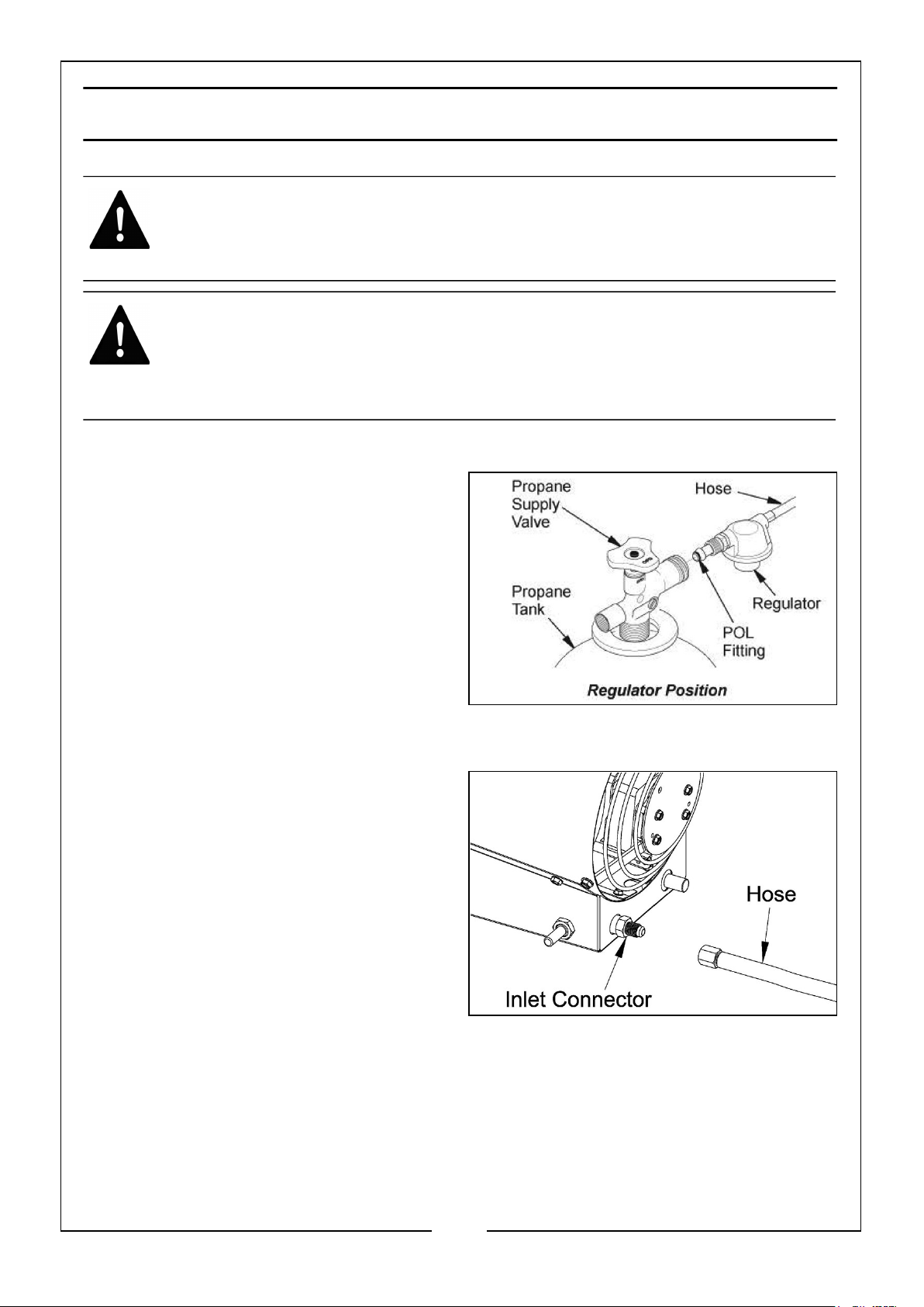
2. Connect POL (Prest-o-Lite) fitting on
hose/regulator assembly to the
propane tank(s).
• Turn POL fitting anti-clockwise
into the threads on the tank.
Tighten firmly using a wrench.
IMPORTANT: Position the regulator
so that the hose leaving the
regulator is in a horizontal position.
This places the regulator vent in
the proper position to protect it from the weather.
3. Connect the hose to the valve inlet
connector. Tighten firmly using a
wrench.
IMPORTANT: Use extra hose or
piping if needed between hose/
regulator assembly and propane
tank. You must use the regulator
supplied with heater.
4. Open the propane supply valve on
the propane tank(s) slowly.
NOTE: If the supply valve is not opened slowly, the check valve on the propane tank
will activate and stop gas flow. If this happens, close the propane supply valve
and open again slowly.
5. Check all connections for leaks. Apply a mixture of liquid soap and water to all gas
joints. Bubbles forming show a leak that must be corrected.
6. Close the propane supply valve.
12
Parts & Service: 020 8988 7400 / E-mail: [email protected] or [email protected]
Page 13

OPERATING SPACE AND AIR SUPPLY
MINIMUM FRESH AIR OPENING REQUIREMENTS
These heaters are specified as having a minimum fresh air opening requirement of
1.5cm2/1400cm2.
OPERATING SPACE
DO NOT obstruct the air intake to the heater and allow the following clearances from
combustible surfaces.
Outlet (Front): 6 feet (1.8 m)
Sides: 6 feet (1.8 m)
Top: 6 feet (1.8 m)
Inlet (Rear): 2 feet (0.6 m)
Keep the heater as far as practical from propane tanks and NEVER point the heater
directly at any propane tank.
13
Parts & Service: 020 8988 7400 / E-mail: [email protected] or [email protected]
Page 14
STARTING PROCEDURE!
WARNING: BEFORE STARTING THE HEATER, YOU MUST ENSURE
THAT THE MINIMUM VENTILATION REQUIREMENTS ARE OBSERVED
TO AVOID THE RISK OF CARBON MONOXIDE POISONING.
TO START THE HEATER
1. Follow all installation, ventilation, and safety information.
2. Locate the heater on stable and level surface.
• Make sure strong drafts do not blow into the front or rear of the heater.
3. Plug the heater into a suitable 230V mains socket.
4. Set the on/off switch to the on position.
• The motor will start, the fan will turn, forcing air from the front of the
heater.
5. Open the propane supply valve on the propane tank(s) slowly.
NOTE: If not opened slowly, the excess-flow check valve on the propane tank will
stop the gas flow. If this happens, close the propane supply valve and open
again slowly.
WARNING: MAKE SURE THAT THE MOTOR AND FAN ARE RUNNING
BEFORE PUSHING IN AUTOMATIC CONTROL VALVE BUTTON.
FLAMES COULD FLASH OUTSIDE HEATER IF THE MOTOR AND FAN
ARE NOT RUNNING.
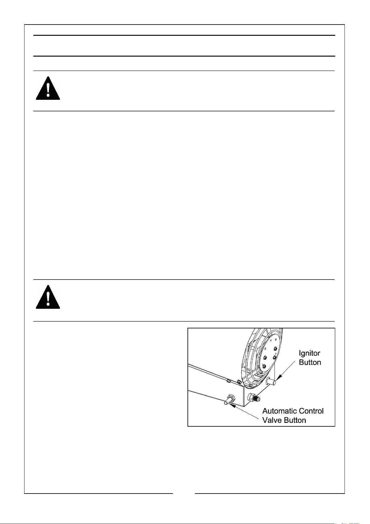
6. Push in and hold the automatic
control valve button.
7. Push the Piezo igniter button.
• You may need to push the Piezo
igniter button 3-8 times until the
burner lights.
• When the burner lights, keep the
automatic control valve button
pushed in.
8. Release the automatic control valve button after 15 seconds.
NOTE: If the heater fails to ignite, the hose may have air in it. If so, keep the
automatic control valve button pressed and wait 20 seconds. Release the
automatic control valve button and wait 20 seconds for unburned fuel to exit
the heater, repeat steps 6-8.
14
Parts & Service: 020 8988 7400 / E-mail: [email protected] or [email protected]
Page 15

STOPPING PROCEDURE
TO STOP THE HEATER
1. Tightly close propane supply valve on propane tank(s).
• The heater will burn away gas left in supply hose.
2. Allow the heater to cool down for 5 minutes, then switch off the heater.
3. Unplug the heater.
TO RESTART THE HEATER
1. Wait five minutes after stopping the heater.
2. Repeat steps under 'To Start The Heater’.
AUTOMATIC SAFETY FEATURES
This heater has the following safety features that will automatically shut down the
heater if they are activated:
1. Thermal Cut Out.
2. Flame Out.
3. Solenoid Valve.
If any of these features are activated, let the heater cool down for 5 minutes before
trying to restart the heater.
15
Parts & Service: 020 8988 7400 / E-mail: [email protected] or [email protected]
Page 16
STORAGE
CAUTION: DISCONNECT THE HEATER FROM PROPANE SUPPLY
TANK(S)
1. Store propane tank(s) in safe manner.
• Follow all local regulations.
• Always store propane tanks outdoors.
2. Place plastic cover caps over any brass fittings, the connector and hose/regulator
assembly.
3. Store in a dry, clean and safe place.
4. When taking heater out of storage, always check inside of heater. Insects and
small animals may place foreign objects in heater.
MAINTENANCE
WARNING: NEVER SERVICE THE HEATER WHILE IT IS PLUGGED IN,
CONNECTED TO THE PROPANE SUPPLY, OPERATING OR HOT.
SEVERE BURNS OR ELECTRIC SHOCK MAY OCCUR.
WARNING: KEEP THE HEATER CLEAR AND FREE FROM ANY
COMBUSTIBLE MATERIALS, GASOLINE AND OTHER FLAMMABLE
VAPOURS AND LIQUIDS.
WARNING: DO NOT BLOCK THE FLOW OF COMBUSTION OR
VENTILATION AIR.
1. Keep heater clean. Clean heater annually or as needed to remove dust and debris.
If heater is dirty or dusty, clean heater with a damp cloth.
2. Inspect the heater before each use. Check connections for leaks. Apply mixture of
liquid soap and water to connections. Bubbles forming show a leak. Correct all
leaks at once.
3. Inspect the hose/regulator assembly before each use. If the hose is highly worn or
cut, replace with a hose specified by the manufacturer.
4. Have heater inspected yearly by a qualified service agency.
5. Keep the inside of the heater free from combustible and foreign objects.
16
Parts & Service: 020 8988 7400 / E-mail: [email protected] or [email protected]
Page 17
TROUBLESHOOTING
WARNING: NEVER SERVICE THE HEATER WHILE IT IS PLUGGED IN,
CONNECTED TO PROPANE SUPPLY, OPERATING OR HOT. SEVERE
BURNS AND ELECTRICAL SHOCK CAN OCCUR.
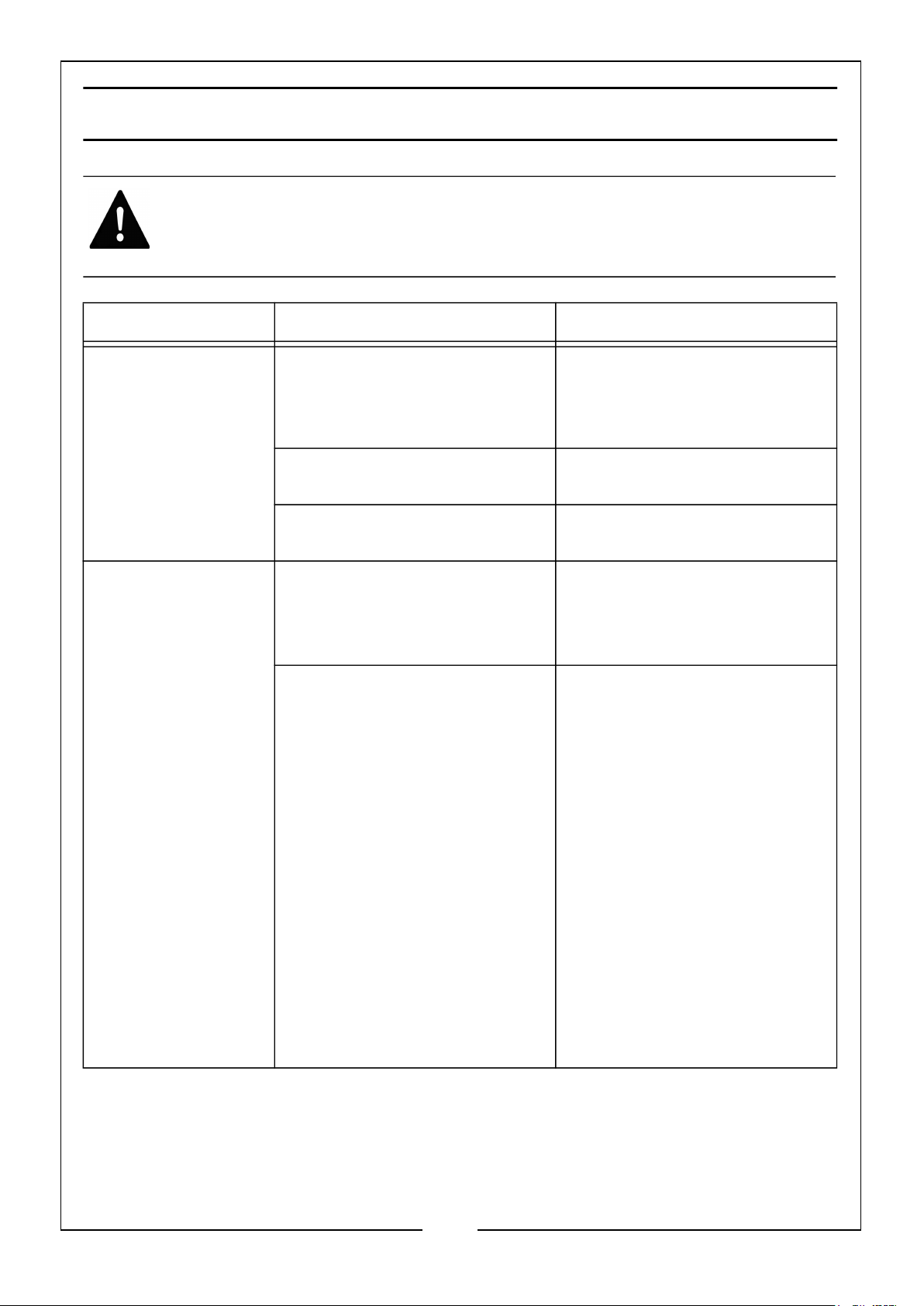
OBSERVED FAULT POSSIBLE CAUSE REMEDY
Fan does not turn
when heater is
plugged in
Heater will not
ignite
No electrical power to the
heater
Structural damage Return to your dealer for
Defective motor Return to your dealer for
User did not follow
installation or operation
instructions properly
No spark at igniter. If no
spark seen, the fault may
be:
A) Loose or disconnected
igniter wire
B) Wrong spark gap
C) Piezo igniter loose
D) Bad igniter electrode
Check voltage to electrical
outlet. If voltage is good,
check heater power cable for
breaks
repair.
repair.
Repeat installation and
operation instructions. See
Installation and Starting,
page 12-15
A) Check igniter wire.
Tighten or reattach loose
igniter wire.
B) Set gap between igniter
electrode and target plate to
0.17" (0.43 cm)
C) Tighten nut holding Piezo
igniter to base of heater
D) Replace igniter electrode.
If you see a spark at the
igniter have the heater
serviced by a qualified
service person.
17
Parts & Service: 020 8988 7400 / E-mail: [email protected] or [email protected]
Page 18

OBSERVED FAULT POSSIBLE CAUSE REMEDY
Heater shuts
down while
running
High surrounding air
temperature causing thermal
limit device to shut down
heater
This can happen when
running heater in
temperatures above 85oF.
Only run the heater in cooler
temperatures
Restricted air flow Check heater inlet and
outlet. Remove any
obstructions
18
Parts & Service: 020 8988 7400 / E-mail: [email protected] or [email protected]
Page 19
SPECIFICATIONS
Model Number DEVIL 600
Dimensions (L x W x H) mm 428x185x275
Weight 4.4kg
Fuse Rating 7A
Operating Voltage 230V/50Hz
Rated Input Power 43W
Rated Input Current 369mA
Electrical Insulation Class I
Energy Efficiency Class D
RPM (@230V@No Load) 2900
Duty Cycle S1 (Continuous)
IP Rating IPX0
Hose Length 1.5m
Regulator M30-700
Fuel Propane
Ignition System Piezo
Regulator Gas Flow Rate (kg/hr) 2
Gas Consumption (kg/hr) 1.05
Air Flow (m3/hr) 190
Gas Pressure (max) 700mBar
Rated Heat Output (kW/btu per hour) 15/51,182
Please note that the details and specifications contained herein are correct at the time
of going to print. However CLARKE International reserve the right to change
specifications at any time without prior notice. ALWAYS consult the heater’s data
plate.
19
Parts & Service: 020 8988 7400 / E-mail: [email protected] or [email protected]
Page 20
Page 21
PARTS LIST
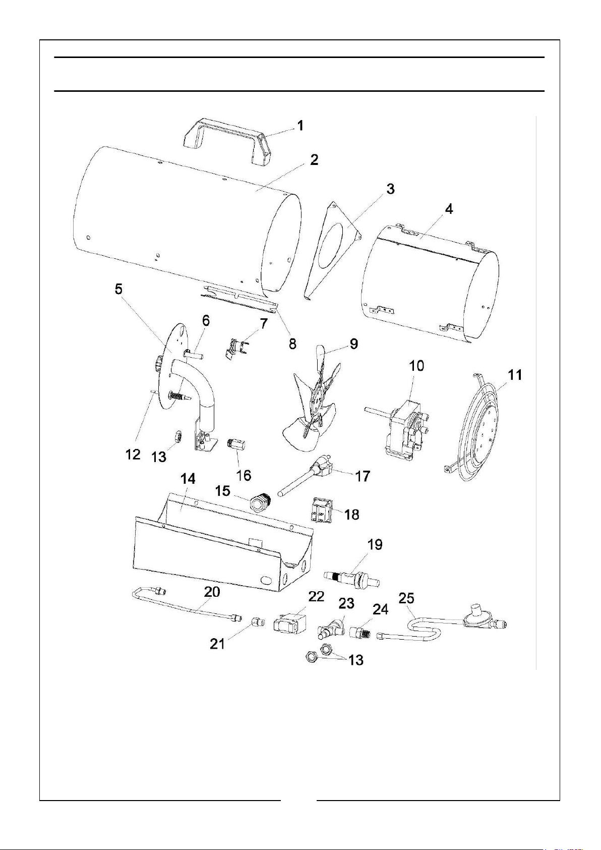
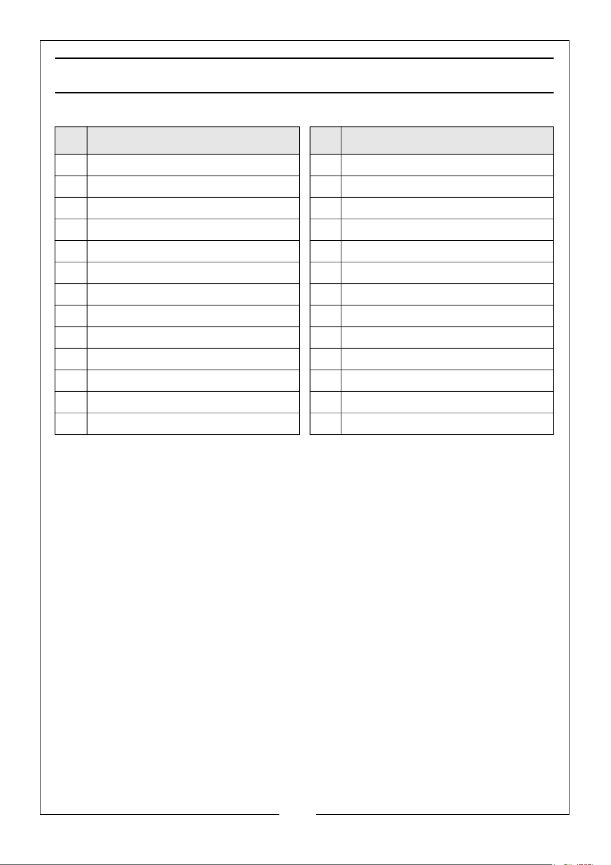
No Description No Description
1 Handle 14 Control Box
2 Outer Cylinder 15 Strain Relief Bush
3 Front Guard 16 Nozzle
4 Middle Cylinder Assembly 17 Power Cable
5 Burner 18 Power Switch
6 Electrode Igniter 19 Piezo Igniter
7 High Limit Control 20 Fuel Tube Assembly
8 Fire Damper Board 21 Extension Fitting
9 Fan 22 Solenoid Valve Assembly
10 Motor 23 Gas Valve
11 Inlet Grille 24 Regulator Connector
12 Thermocouple 25 Hose/Regulator Assembly
13 Nut
21
Parts & Service: 020 8988 7400 / E-mail: [email protected] or [email protected]
Page 22
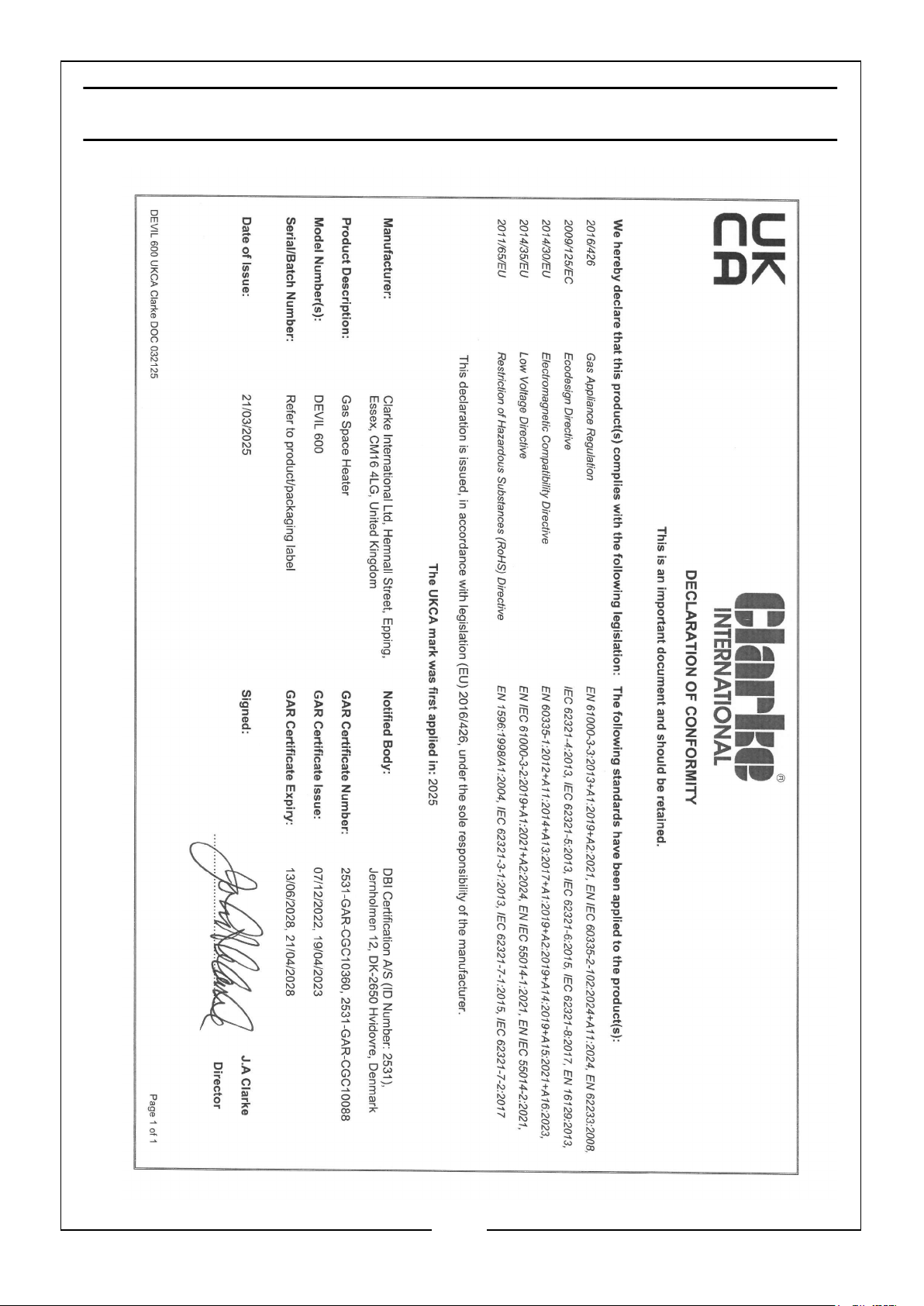
DECLARATION OF CONFORMITY - UKCA
22
Parts & Service: 020 8988 7400 / E-mail: [email protected] or [email protected]
Page 23
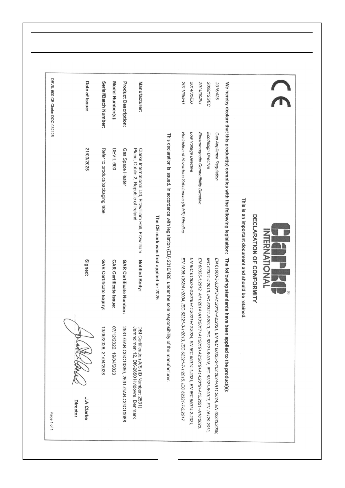
DECLARATION OF CONFORMITY - CE
23
Parts & Service: 020 8988 7400 / E-mail: [email protected] or [email protected]
Page 24

 Loading...