

Page 1
FAN HEATER
FAN HEATER
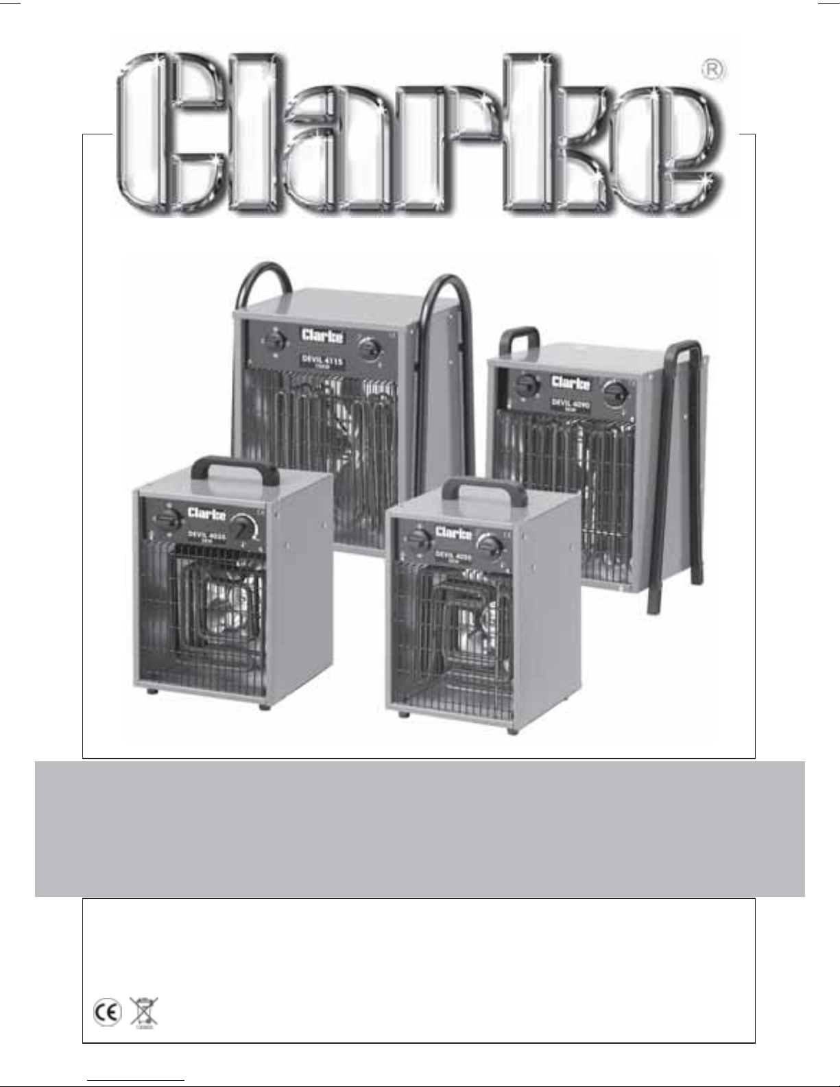
Models: DEVIL 4035 • 4055 • 4090 • 4115
OPERATING & MAINTENANCE
INSTRUCTIONS
0705
Page 2

DECLARATION of CONFORMITY
We declare that this product complies with the following standards/directives:
• 73/23/EEC
• 98/336/EEC
Serial/Batch No: See Data Plate
signed
SPECIFICATIONS
Model Number Devil 4035 Devil 4055 Devil 4090 Devil 4115
Input 230V 50hz 1ph 400V 50hz 3ph 400V 50hz 3ph 400V 50hz 3ph
Output Rating 1.5 - 3kW 2.5 - 5kW 3, 6 & 9kW 7.5 - 15kW
Absorbed Power 3kW 5kW 9kW 15kW
Fuse Rating 13A 15A 15A 25A
Dimensions (mm) 250x250x420 250x250x420 380x330x590 440x350x600
Air Output 400m3/h 400m3/h 800m3/h 1300m3/h
Noise Level 50dBL
Gross Weight 7.5kg 8.0kg 13.5kg 15.5kg
Part No. 6925140 6925145 6925150 6525155
WA
50dBL
WA
52dBL
WA
54dBL
WA
PARTS & SERVICE
PARTS & SERVICE TEL: 020 8988 7400
or e-mail as follows:
PARTS: [email protected]
SERVICE: [email protected]
Waste electrical products should not be disposed of with household waste. Please
dispose of at your local recycling facility.
© Copyright Clarke International. All rights reserved Feb. 2002
2
Page 3
Thank you for purchasing this Clarke Ceramic Heater.
Before attempting to operate the unit please read this instruction leaflet and carefully
follow all directions given. By doing so you will ensure safe operation of the unit and you
can also look forward to it providing you with long and trouble free service.
GUARANTEE
This CLARKE product is guaranteed against faults in manufacture for 12 months
from purchase date. Please keep your receipt as proof of purchase.
This guarantee is invalid if the product has been found to have been abused in
any way, or not used for the purpose for which it was intended, or to have been
tampered with in any way. The reason for return must be clearly stated.
This guarantee does not affect your statutory rights.
SAFETY PRECAUTIONS
• NEVER use electrical equipment in the presence of combustible gases.
• This heater is for INDOOR USE ONLY.
• ALWAYS disconnect from the mains supply before moving or performing any
maintenance tasks.
• ALWAYS use in an upright position ONLY.
• Inspect the mains cable regularly for signs of damage. DO NOT use if it is
damaged, and ALWAYS keep it away from the source of heat.
• NEVER switch ON the heater if the guard is removed.
• NEVER locate the heater near combustible materials such as curtains, furniture
etc. Allow at least 1 metre distance.
• DO NOT use this heater in a bathroom , shower room, in the vicinity of a
swimming pool, or any wet environment.
• DO NOT locate the heater close to an adjacent wall or ceiling...allow a
distance of at least 1 metre from a wall or ceiling.
• NEVER cover the heater, or block any of the vents.
• DO NOT use if the heater elements are damaged or broken.
• NEVER touch the heater for at least 15 minutes after it is switched off.
• DO NOT leave the heater unnattended.
• If children are present.....ALWAYS use with a fireguard.
• Do NOT use in a paint spray booth or any explosive environment.
• Take care to ensure that the fan grille cannot be blocked by curtains or the like.
3
Page 4
ELECTRICAL CONNECTIONS
Devil 4035
This model is provided with a 13 amp BS 1363 plug, fitted with a 13amp fuse and
MUST be connected to a standard, 230 Volt (50Hz) electrical supply, preferably
through an approved plug , or a suitably fused isolator switch.
WARNING! THIS APPLIANCE MUST BE EARTHED
IMPORTANT: The wires in the mains lead are coloured in accordance with the
following code:
Green & Yellow ........................ Earth
Blue ............................................ Neutral
Brown ........................................ Live
As the colours of the flexible lead of this appliance may not correspond with the coloured
markings identifying terminals in your plug, or your mains supply, proceed as follows:
• Connect GREEN & YELLOW coloured cord to plug terminal marked with a letter “E” or
Earth symbol “ ” or coloured GREEN or GREEN & YELLOW.
• Connect BROWN cord to terminal marked with a letter “L” or coloured RED.
• Connect BLUE cord to terminal marked with a letter “N” or coloured BLACK.
Fuse Rating
The fuse in the plug must be replaced with one of the same rating (13 amps) and this re-
placement must be ASTA approved to BS1362.
This appliance is fitted with a plug which is moulded on to the electric cable (i.e. nonrewireable) please note:
1. The plug must be thrown away if it is cut from the electric cable. There is a danger of
electric shock if it is subsequently inserted into a socket outlet.
2. Never use the plug without the fuse cover fitted.
3. Should you wish to replace a detachable fuse carrier, ensure that the correct
replacement is used (as indicated by marking or colour code).
4. Replacement fuse covers can be obtained from most DIY or electrical stores.
Devils 4055, 4090 & 4115
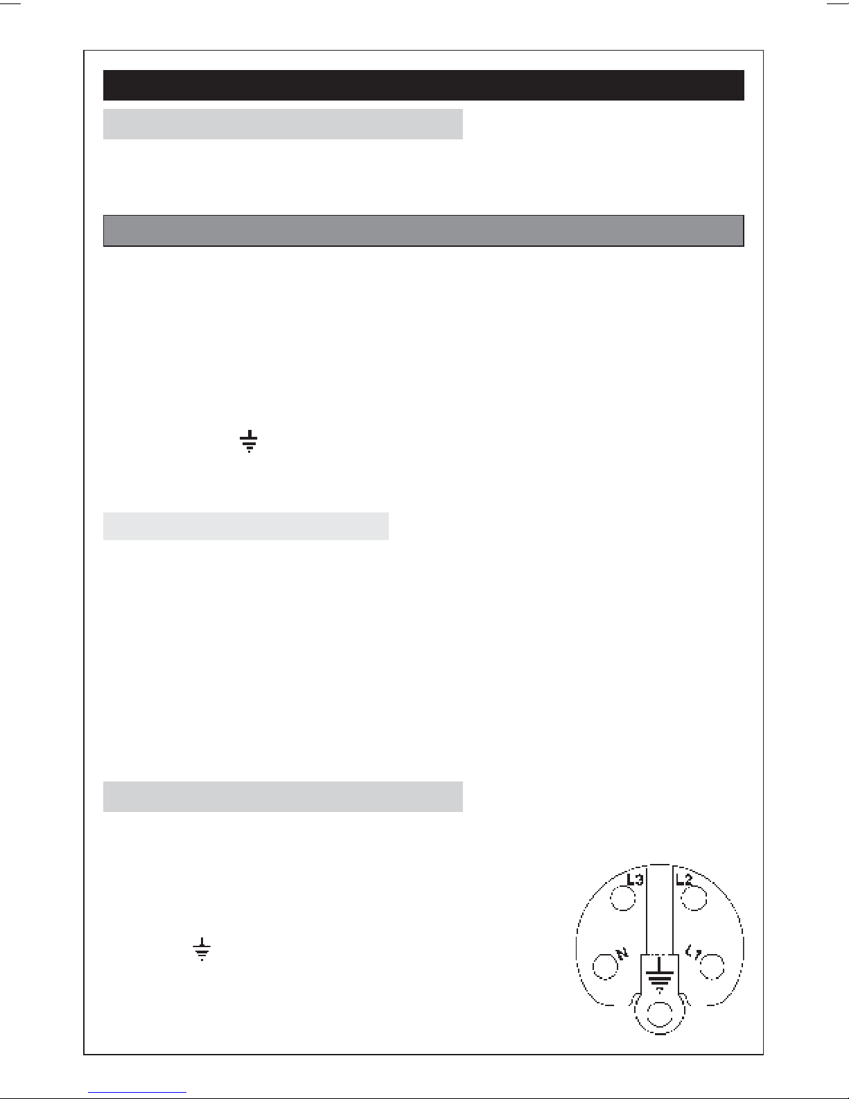
These machines MUST be connected to a 400 Volt, 3 PHASE 50Hz supply through a suitably
fused isolator switch. It cannot be operated from a single phase supply.
A trailing socket is provided and should be wired as follows:
• Connect the GREEN or GREEN & YELLOW coloured wire,
to the terminal marked with the letter “E” or Earth
symbol “ ”
• Connect the BLACK wire to the ‘N’ or Neutral terminal.
• Connect the Remaining wires to the terminals marked
`L1, L2 and L3.
4
Page 5
WARNING!
IF YOU ARE IN ANY DOUBT ABOUT ELECTRICAL CONNECTIONS, CONSULT A
QUALIFIED ELECTRICIAN.
DO NOT ATTEMPT ELECTRICAL CONNECTIONS or REPAIRS YOURSELF.
OPERATION
With the heater suitably sited (ensure you comply with all safety precautions),
switch the heater ON to either half or full output. Model Devil 4090 has three settings
- 1/3, 2/3 and full power (see specification chart on page 2).
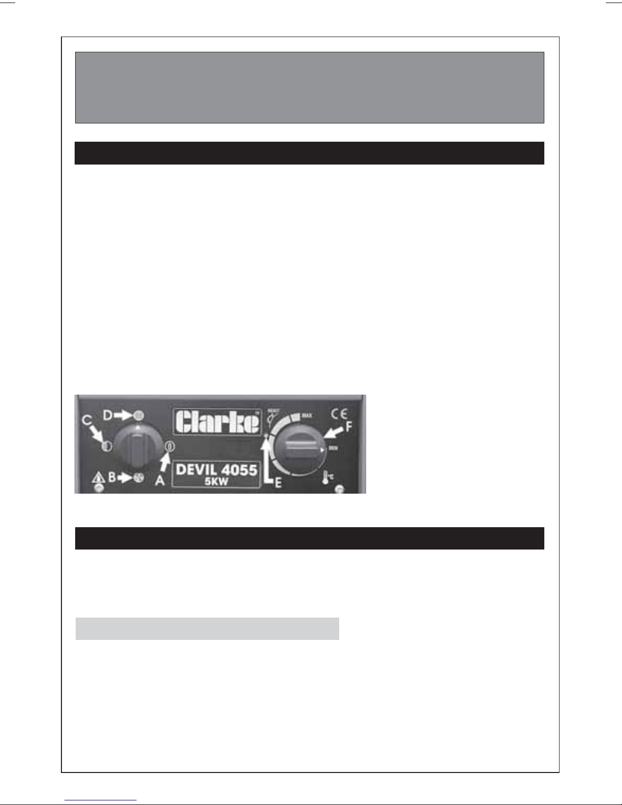
A temperature control (F) is also provided for fine control of heat output.
Should the unit overheat, a thermal cutout will operate, shutting down the unit.
Allow a period of time for the unit to cool (approx. 10 minutes) before pressing the
reset using a suitable tool, and restarting.
When switching the unit OFF, it is strongly recommended that the unit is run in the
FAN ONLY mode for approx. 10 minutes, in order to cool the elements, before
switching OFF completely and finally disconnecting from the mains supply.
The thermal cutout may also operate if the heater is shut down without allowing
to cool sufficiently. If, subsequently, the machine fails to start, press the reset using
a suitable tool and try again.
A. Off
B. Fan only
C. Half Power output*
D. Full power output*
E. Reset
F. Temperature Control
* with temperature control at MAX.
NOTE: Model 4090 is provided with 3 heat settings: 1/3, 2/3 and full power
MAINTENANCE
Before performing any maintenance tasks, if the heater has been used, ALWAYS
allow it to cool down for at least 10 minutes (by switching the heater OFF, but
leave the fan running), then disconnect from the mains supply.
Periodically.
• Disconnect from the mains supply, and use compressed air to clean out the
unit. ALWAYS wear a dust mask to perform this operation.
If there is any serious build up of dirt, remove the front and rear grilles and
clean the fan and elements thoroughly with a damp cloth
• Inspect the mains cable for damage. Heat damage will cause the cable to
stiffen and crack. If this is found, have the cable replaced. Check cable routing
and ensure it is well away from the heat source.
5
Page 6
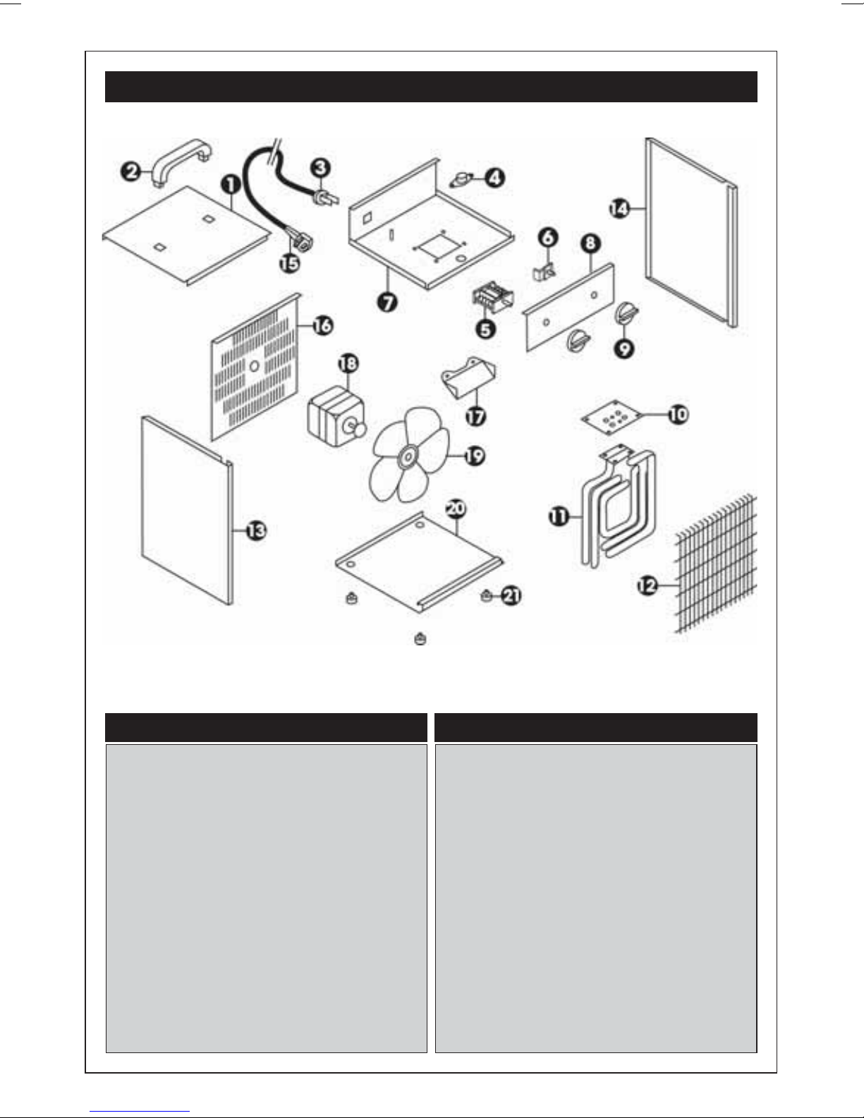
SPARE PARTS - DEVIL 4035 & 4055
No. Description Part No.
1 Top Plate RP24113041
2 Handle RP45050009
3 Grommet Assy RP18480018
4 Thermal Cut-out RP17120201
5 Switch Unit RP17251108
6 Temp. Control RP17120100
7 Mounting Box RP21113002
8 Front Panel RP29430410
9 Knob RP18508008
10 Insulation Plate RP27450005
11 Heating Element RP17141003
No. Description Part No.
12 Front Grille RP23115060
13 Side Panel - L RP21115071
14 Side Panel - R RP21115070
15 Mains cable RP74250014
16 Rear Grille RP21113350
17 Heat Shield RP25112074
18 Motor RP17801000
19 Fan RP17802322
20 Base RP21115012
21 Foot RP45071021
7
Page 7
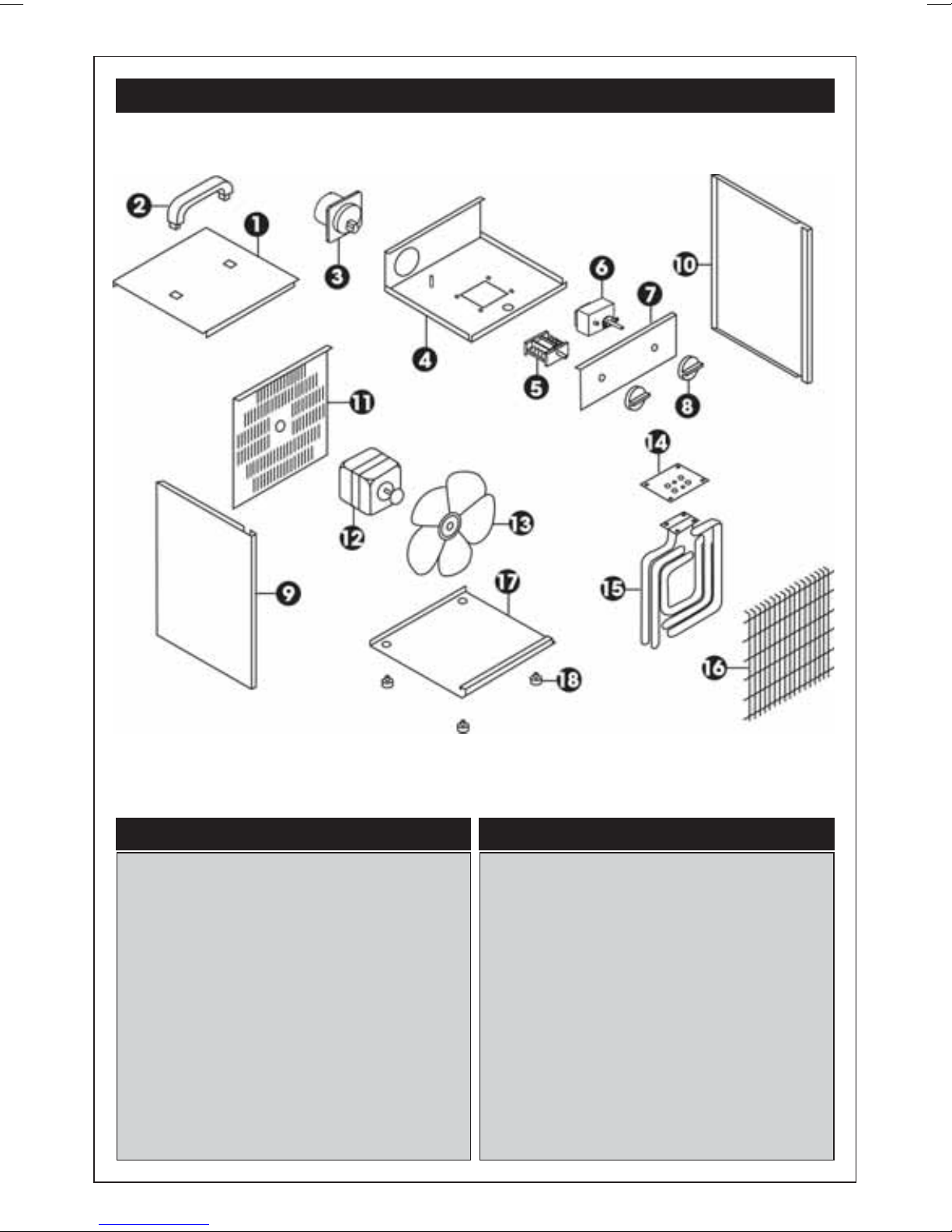
SPARE PARTS - DEVIL 4055
No. Description Part No.
1 Top Plate RP24115041
2 Handle RP45050009
3 Plug Assy 16A RP17110055
4 Mounting Box RP21115002
5 Switch Unit RP17251108
6 Temp. Control RP17120105
7 Front Panel RP29440410
8 Knob RP18508008
9 Side Panel - L RP21115071
10 Side Panel - R RP21115070
No. Description Part No.
11 Rear Grille RP21113350
12 Motor RP17801004
13 Fan RP17802526
14 Insulation Plate RP27450003
15 Heating Element RP17141003
16 Front Grille RP23115060
17 Heat Shield RP25112074
18 Base RP21115012
19 Foot RP45071021
- Trailing Socket RP17110053
7
Page 8
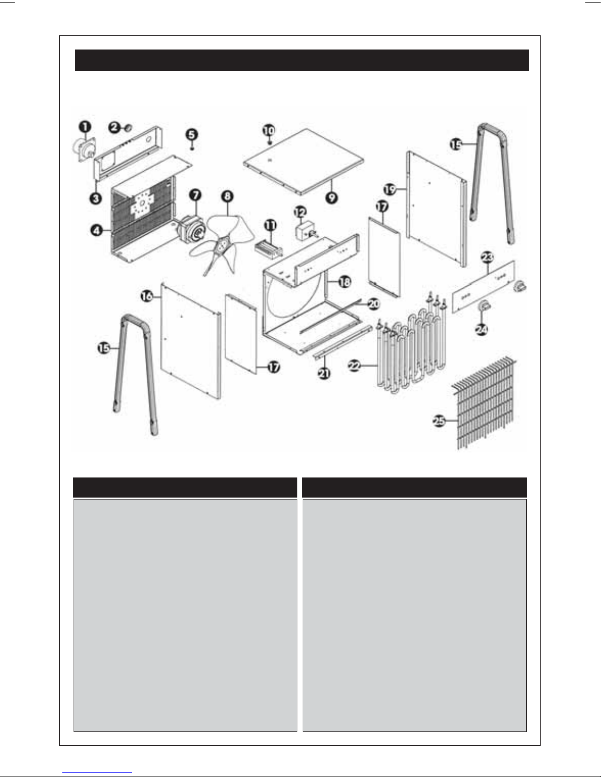
SPARE PARTS - DEVIL 4090
No. Description Part No.
1 Plug Assy 16A RP17110055
2 Grommet RP44470020
3 Mounting Plate RP21221090
4 Rear Grille RP21220280
5 Grommet RP44470029
7 Motor RP17801017
8 Fan RP17802626
9 Top Panel RP24221232
10 Plug RP44610012
11 Switch Unit RP17251111
12 Temp. Control RP17120105
15 Handle RP45220260
No. Description Part No.
16 Side Panel - L RP21221253
17 Heat Shield Bkt RP21221100
18 Mounting Box RP21221002
19 Side Panel - R RP21221252
20 Retainer Bkt RP21220120
21 Grille Fittings RP21221162
22 Heating Element RP17141022
23 Front Panel RP29893410
24 Knob RP18508008
25 Front Grille RP23221150
- Trailing Socket RP17110053
8
Page 9
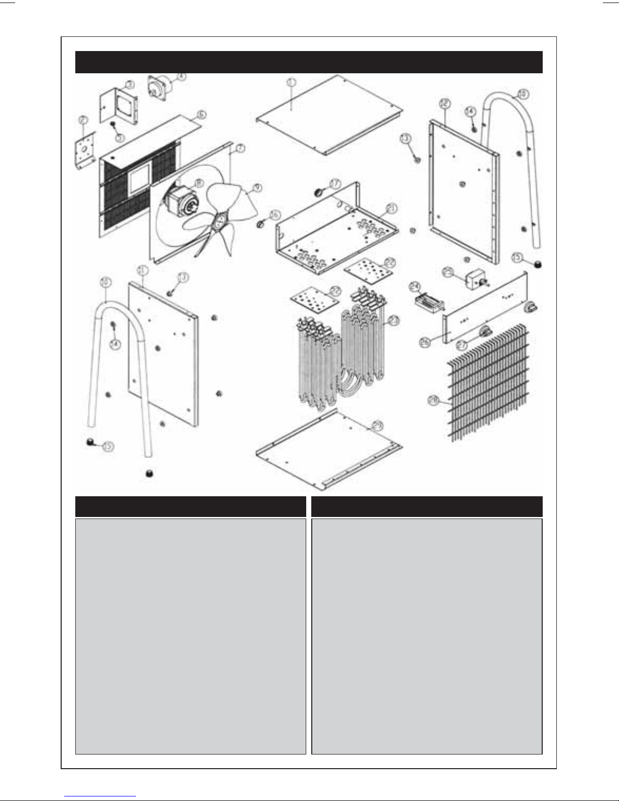
SPARE PARTS - DEVIL 4115
No. Description Part No.
1 Top Plate RP24119602
2 Motor Fittings RP22119172
3 Mounting Bkt RP22119015
4 Appliance Inlet 32A RP17110056
5 Grommet RP44470015
6 Rear Grille RP21119157
7 Fan Cowl RP22201015
8 Motor RP17801002
9 Fan RP17802934
10 Pipe Holder RP25119083
11 Side Plate Left RP23119632
12 Side Plate Right RP23119622
13 Insulation Bush Male Vb RP44550009
14 Insulation Bush Male Vb RP44550010
15 Foot RP44610004
No. Description Part No.
16 Rubber Grommet RP18480022
17 Grommet RP44470020
18 Fuse RP17172041
19 Fuse Holder RP17160011
20 Grommet RP44470008
21 Mounting Box RP21119601
22 Insulation Sheet RP27450006
23 Heat Element RP17141000
24 Switch Assy RP17251103
25 Temp. Regulator RP17120105
26 Front Panel RP29505410
27 Knob RP18508008
28 Front Grille RP23119166
29 Base RP23119612
- Trailing Socket 32A RP17110052
9
Page 10
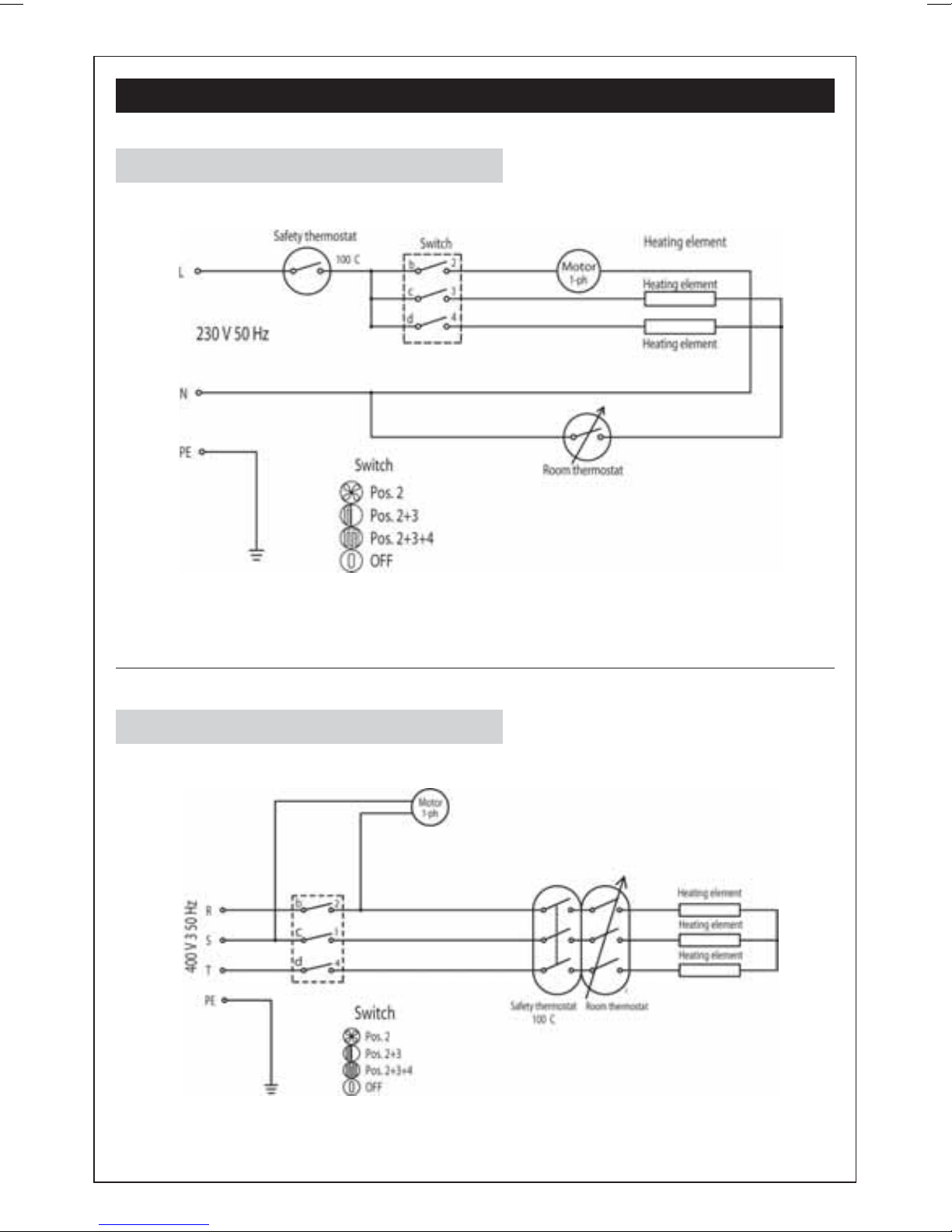
WIRING DIAGRAMS
Devil 4035
Devil 4055
10
Page 11
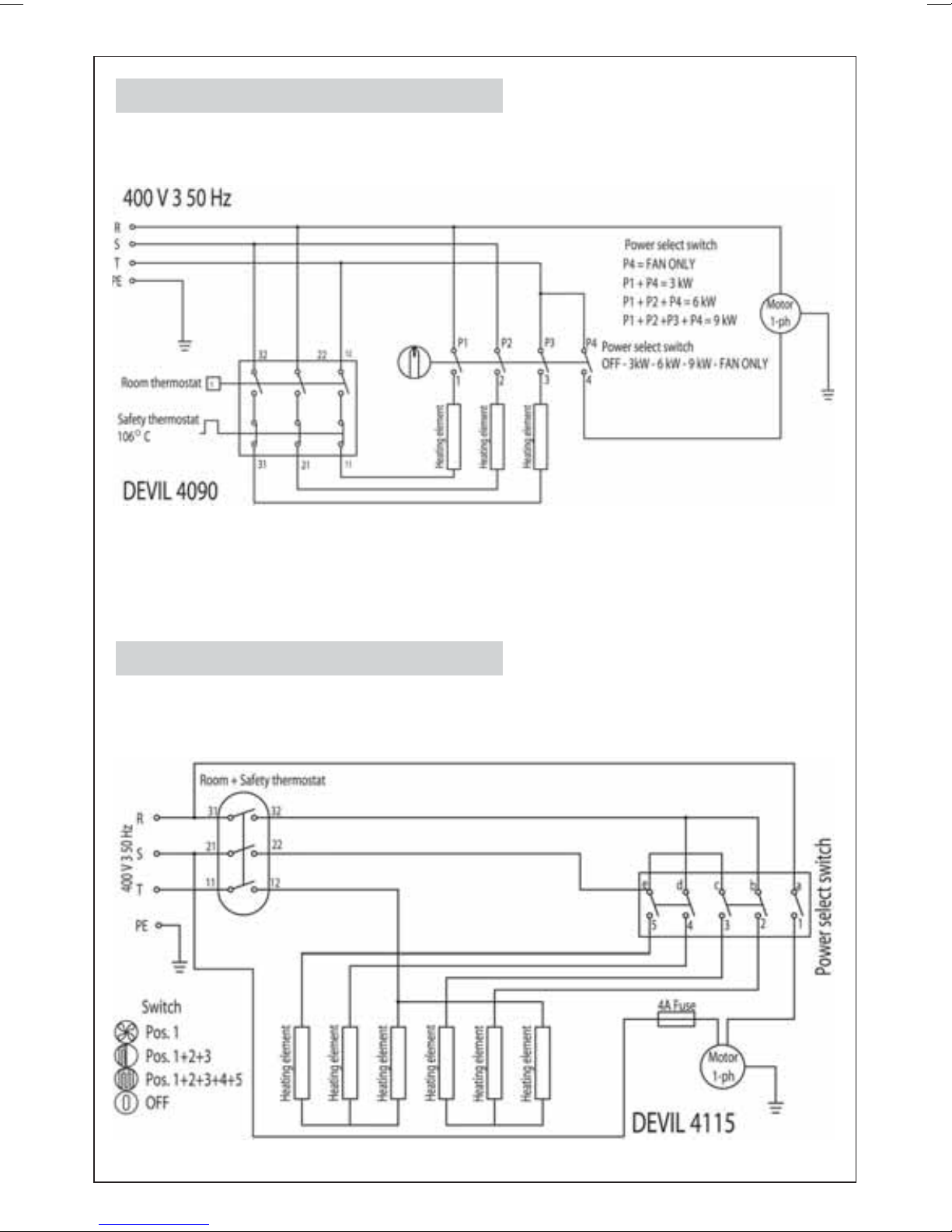
Devil 4090
Devil 4115
11
 Loading...