

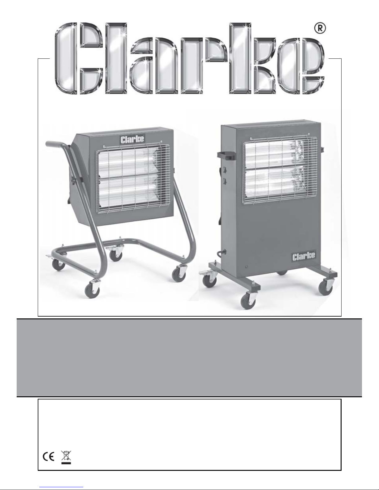
Clarke Devil 370P, Devil 370SP, Devil 371P, Devil 371SP Operating & Maintenance Instructions
Page 1
OPERATING & MAINTENANCE
INSTRUCTIONS
Devil 370P, 370SP, 371P & 371SP
Part Nos: 6926000, 6926005, 6926010 & 6926015
GC0210
DEVIL QUARTZ INFRA-RED
HALOGEN HEATERS
Page 2
2
INTRODUCTION
Thank you for purchasing this CLARKE Quartz Halogen Infra-red Heater.
Please read this manual thoroughly and follow the instructions carefully.
Before attempting to use the heater, thoroughly familiarise yourself with the
heater & its operation. In doing so you will ensure the safety of yourself and
that of others around you, and you can look forward to the heater giving you
long and satisfactory service.
GUARANTEE
This product is guaranteed against faulty manufacture for a period of 12
months from the date of purchase. Please keep your receipt which will be
required as proof of purchase.
This guarantee is invalid if the product is found to have been abused or
tampered with in any way, or not used for the purpose for which it was
intended.
Faulty goods should be returned to their place of purchase, no product can
be returned to us without prior permission.
This guarantee does not effect your statutory rights.
ENVIRONMENTAL PROTECTION
Do not dispose of this product with general household waste. This
product contains valuable raw materials and must be disposed of
according to the laws governing Waste Electrical and Electronic
Equipment, at a recognised disposal facility.
Page 3

3
GENERAL SAFETY RULES
1) WORK AREA
1. These heaters are for INDOOR USE ONLY.
2. Do not expose the heater or power cable to rain or wet conditions. Any
water entering the heater will increase the risk of electric shock. DO NOT
use this heater in a bathroom, shower room or any other wet environment.
3. NEVER locate the heater near combustible materials such as curtains,
furniture etc. Allow at least 1 metre distance.
4. DO NOT locate the heater close to an adjacent wall or low ceiling. Allow
a distance of at least 1 metre from a wall or ceiling. Avoid placing the
heater directly below power socket outlets.
5. Take care to ensure that the wire guard cannot be covered.
6. Do not operate heater in explosive atmospheres such as in the presence
of flammable liquids, gases or dust such as in a paint spray booth or any
explosive environment.
7. Never stand the heater on a movable vehicle where it could tip over.
8. Do not allow the halogen tubes to become covered with dust which
could become a fire hazard. If used in a dusty workplace it should be
cleaned as described under Cleaning and Maintenance.
9. NEVER touch the halogen tubes for at least 15 minutes after switching off.
10. DO NOT leave the heater unattended.
11. If children are present always use with a fireguard.
12. Store the heater out of the reach of children and do not allow persons
unfamiliar with these instructions to operate it.
13. Do not use this heater with a programmable timer used to switch it on
automatically.
14. Use ONLY in an upright position.
2) ELECTRICAL SAFETY
1. Electrical appliances must match the power outlet. Never modify the plug
in any way. Do not use adaptor plugs with earthed (grounded)
appliances. Correct plugs and outlets will reduce the risk of electric shock.
2. Do not abuse the electrical cable. Never use the cable for pulling or
unplugging the heater. Keep the cable away from sources of heat, oil,
sharp edges or moving parts. Damaged or tangled cables increase the
risk of electric shock.
3. Keep the mains cable well away from machines and ensure an adequate
electrical supply is close at hand so that the operation is not restricted by
the length of the cable.
Page 4
4
4. ALWAYS disconnect from the mains supply before moving the heater, or
performing any cleaning or maintenance tasks.
5. Inspect the mains cable regularly for signs of damage. DO NOT use if it is
damaged, and ALWAYS keep it away from the source of heat.
6. Check the heater for damage before use. DO NOT use if the heater tubes
are damaged or broken. Any damage should be properly repaired or the
part replaced. If in doubt, DO NOT use. Consult your local Clarke dealer.
3) SERVICE & REPAIRS
1. If necessary, have your heater repaired by a qualified person using
identical replacement parts. This will ensure that the safety of the
appliance is maintained.
Additionally, please keep these instructions in a safe place for future
reference.
ELECTRICAL CONNECTIONS
DEVIL 370P & 370SP HEATER UNITS
The 370 models are provided with a 13 amp BS 1363 plug, fitted with a 13amp fuse
and MUST be connected to a standard, 230 Volt (50Hz) electrical supply, preferably
through a suitably fused isolator switch.
WARNING: THIS APPLIANCE MUST BE EARTHED
IMPORTANT: The wires in the mains lead should be wired up in accordance
with the following colour code:
Green & Yellow - Earth
Blue - Neutral
Brown - Live
As the colours of the flexible cable of this appliance may not correspond with
the coloured markings identifying terminals in your plug, proceed as follows:
•
Connect the GREEN & YELLOW coloured cord to the plug terminal
marked with a letter E or Earth symbol “
” or coloured GREEN or
GREEN & YELLOW.
• Connect the BROWN coloured cord to the plug terminal marked a
letter “L” or coloured RED.
•
Connect the BLUE coloured cord to the plug terminal marked a
letter “N” or coloured BLACK.
Page 5

5
If this appliance is found to be fitted with a plug which is moulded on to the
electric cable (i.e. non-rewireable) please note:
1. The plug must be thrown away if it is cut from the electric cable. There is a
danger of electric shock if it is subsequently inserted into a socket outlet.
2. Never use the plug without the fuse cover fitted.
3. Should you wish to replace a detachable fuse carrier, ensure that the
correct replacement is used (as indicated by marking or colour code).
4. Replacement fuse covers can be obtained from your local Clarke dealer
or most electrical stockists.
FUSE RATING
The fuse in the plug must be replaced with one of the same rating and this
replacement must be ASTA approved to BS1362.
We strongly recommend that this machine is connected to the mains supply
via a Residual Current Device (RCD).
DEVIL 371P & 371SP HEATER UNITS
The 371 models MUST be connected to a 110 Volt, 1 phase 50Hz supply
through a suitably fused isolator switch. On no account must a 230V, 13amp
(BS1363) plug be used.
NOTE: If a portable 110V transformer is used, make sure it has a rated
capacity sufficient to take the load of the heater.
In the event that the heater is hard wired into the electrical system, it must be
carried out in accordance with IEE regulations.
The user should purchase a suitable connecting lead which is compatible
with the appliance socket. A length of 2-3 metres is recommended as giving
mobility to the heater but without becoming a trip hazard.
If in any doubt, consult a qualified electrician. DO NOT attempt any electrical
repairs yourself.
Page 6
6
UNPACKING AND ASSEMBLY
Before assembling, please check contents against the following list and
advise your dealer immediately if any parts are missing.
1 x Heater 4 x Castors (2 with brakes)
2 x Halogen Lamps 2 x Support Legs (P only)
1 x Frame (SP only) 2 x Securing Knobs (SP only)
2 x Saddle Supports (SP only) 2 x Handles (P only)/1 x Handle (SP only)
1 x Fixings pack
TOOLS REQUIRED
7mm, 13mm and 14mm spanners, pozidrive
(phillips) screwdriver
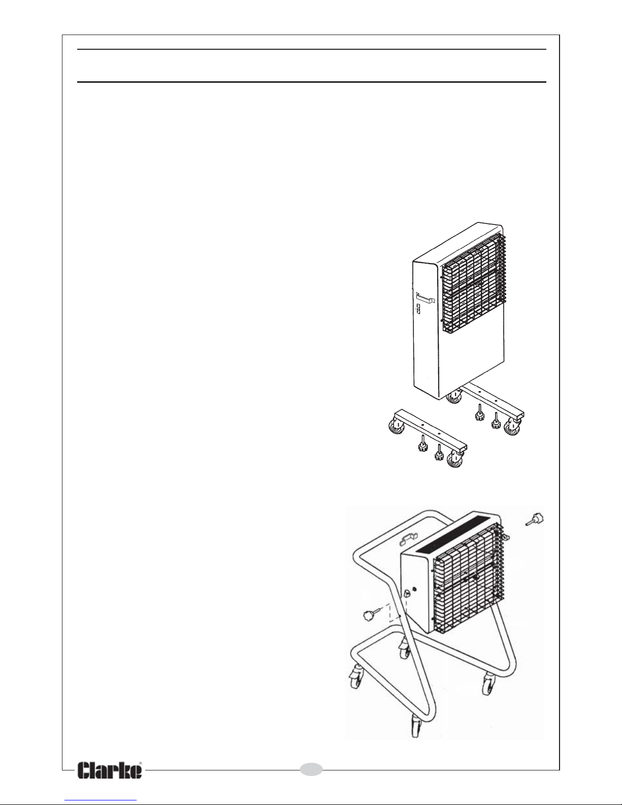
DEVIL 370 /371P
1. Attach the four castors to the support legs
using the 13mm nuts.
2. Attach the legs to the main body using
14mm securing bolts supplied.
3. Attach the handles to each side of the
heater body using the screws supplied.
4. Fit the halogen lamps (see page 7).
DEVIL 370SP/371SP
1. Attach the four castors to the frame
using the 13mm nuts.
2. Attach the handle to the heater body
using the screws supplied.
3. Attach the frame to the heater body
as shown in the drawing, using the
securing knobs and the plastic saddle
supports located either side of the
frame tubing.
4. Fit the halogen lamps (see page 7).
Page 7
7
OPERATION
1. Position the heater where required, and lock the castors to prevent the
heater from rolling.
2. Slacken the locking knobs and rotate the heater body to the required
angle. Tighten the securing knobs on each side to lock into place (SP
models only).
3. Connect the mains cable to a suitable power supply.
4. Use the on/off switches to turn on either one, or both heating elements.
IMPORTANT!
When using the SP model heaters, the angle of tilt MUST NOT exceed 45
degrees downwards, as this could lead to the heater overheating. NEVER
position the heater pointing vertically downwards.
CLEANING & MAINTENANCE
If the heater has been used, ALWAYS allow it to cool down for at least 15
minutes and disconnect from the mains supply before performing any
maintenance tasks.
PERIODICALLY
• If there is any serious build up of dirt, wipe thoroughly with a damp cloth.
Take care that no moisture enters the heater. Take care NOT to touch the
tubes with your fingers.
• Inspect the mains cable for damage. Undue heat will cause the cable to
stiffen and crack. If this is found, have the cable replaced. Check cable
routing and ensure it is well away from the heat source.
• Ensure heating lamps are clear of dust (use compressed air to clean if
possible. (ALWAYS wear a dust mask if performing this operation)
• Refer to your CLARKE dealer if internal maintenance is required.
• When storing the heater, allow it to cool down, then place it in its packing
box for storage in a dry, ventilated place.
FITTING/ REPLACING LAMPS
Before attempting to fit/replace halogen lamps, ensure the heater is
switched off and isolated from the main electrical supply by removing the
plug from the socket.
NEVER handle the heater lamps with bare hands. ALWAYS handle using either
a soft clean glove or a piece of soft clean cloth wrapped around the lamp.
Page 8
8
1. Loosen and remove the two pozidrive screws securing the wire guard,
remove the guard and store removed parts safely.
2. To remove lamp, grasp lamp and gently but firmly push it to one end of
the heater. The lamp holders are spring loaded and will allow the lamp
sufficient movement to clear the opposite holder.
3. Remove the lamp and dispose of, according to local regulations.
4. Fit new halogen lamp in reverse order, repeat procedure for second tube.
5. Replace the guard using the screws removed earlier.
The heater is now ready for use again and may be plugged in and
switched on.
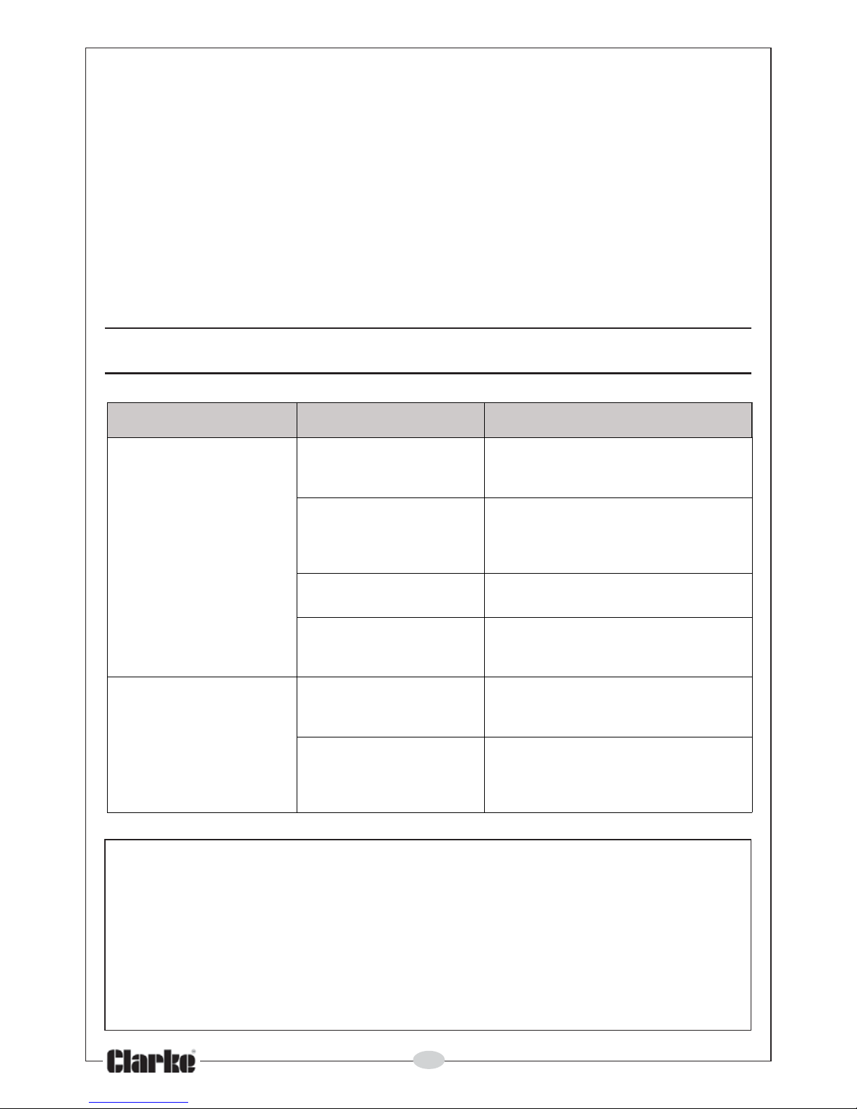
FAULT FINDING
melborP esuaCelbissoP ydemeR
tonseodretaeH
hguohtla,etarepo
dnanideggulp
.nodehctiws
dab/esoolsigulP
.noitcennoc
ehtkcehc&tuogulpe
htlluP
dnagulpehtfonoitcennoc
.tekcos
nwolbesuFdnayrassecenfiecalpeR
swolbesuffI.esuacetagitsevni
EKRALCruo
ytlusnoc,yldetaeper
.relaed
tekcostarewopoN
.teltuo
elbatiusanigulpehttresnI
.tekcos
sihctiwsytefastliT
.tin
ugnilbasid
hctiwsfI.thgirpusitinuerusnE
ruoytlusnoc,tes-ertonseod
.relaedEKRALC
tnemelegnitaeH
.tohgniwolg
hgihootegatlovtupnI
.wolootro
niylppusrewopaesU
gnitarehthtiwecnadrocca
.lebalehtno
yltrapsitelniriA
.dekco
lb
yawatpeksiretaehehterusnE
slairetamrostcejboynamorf
ehtrevocyllaitrapdluochcihw
.tiotninwardebrodrauge
riw
For parts & Servicing, please contact your nearest dealer, or
CLARKE International, on one of the following numbers.
PARTS & SERVICE TEL: 020 8988 7400
PARTS & SERVICE FAX: 020 8558 3622
or e-mail as follows:
PARTS: [email protected]
SERVICE: [email protected]
Page 9
9
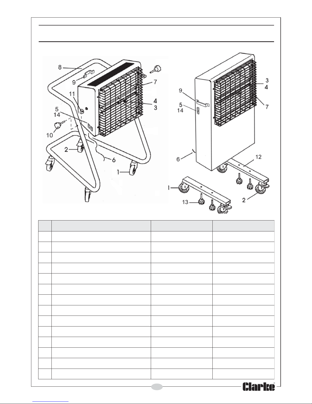
COMPONENT PARTS
oN noitpircseD 073liveD 173liveD
1)dradnats(rotsaC10073VEDGW10173VEDGW
2ekarBhtiwrotsaC20073VEDGW20173VEDGW
3paCdnEcimareC30073VEDGW30173
VEDGW
4ebuTnegolaHztrauQ40073VEDGW40173VEDGW
5hctiwSFFO/NO50073VEDGW50173VEDGW
6elbaCrewoP60073VEDGW60173VEDGW
7dra
uGeriW70073VEDGW70173VEDGW
8)ylnoPS(emarF80073VEDGW80173VEDGW
9eldnaHcitsalP90073VEDGW90173VEDGW
01)ylnoPS(bonKgn
iruceS01073VEDGW01173VEDGW
11)ylnoPS(elddaScitsalP11073VEDGW11173VEDGW
21)ylnoP(raBtroppuS21073VEDGW21173VEDGW
3
1)ylnoP(tloBgniruceS31073VEDGW31173VEDGW
41hctiwSytefaStliT41073VEDGW41173VEDGW
Page 10
10
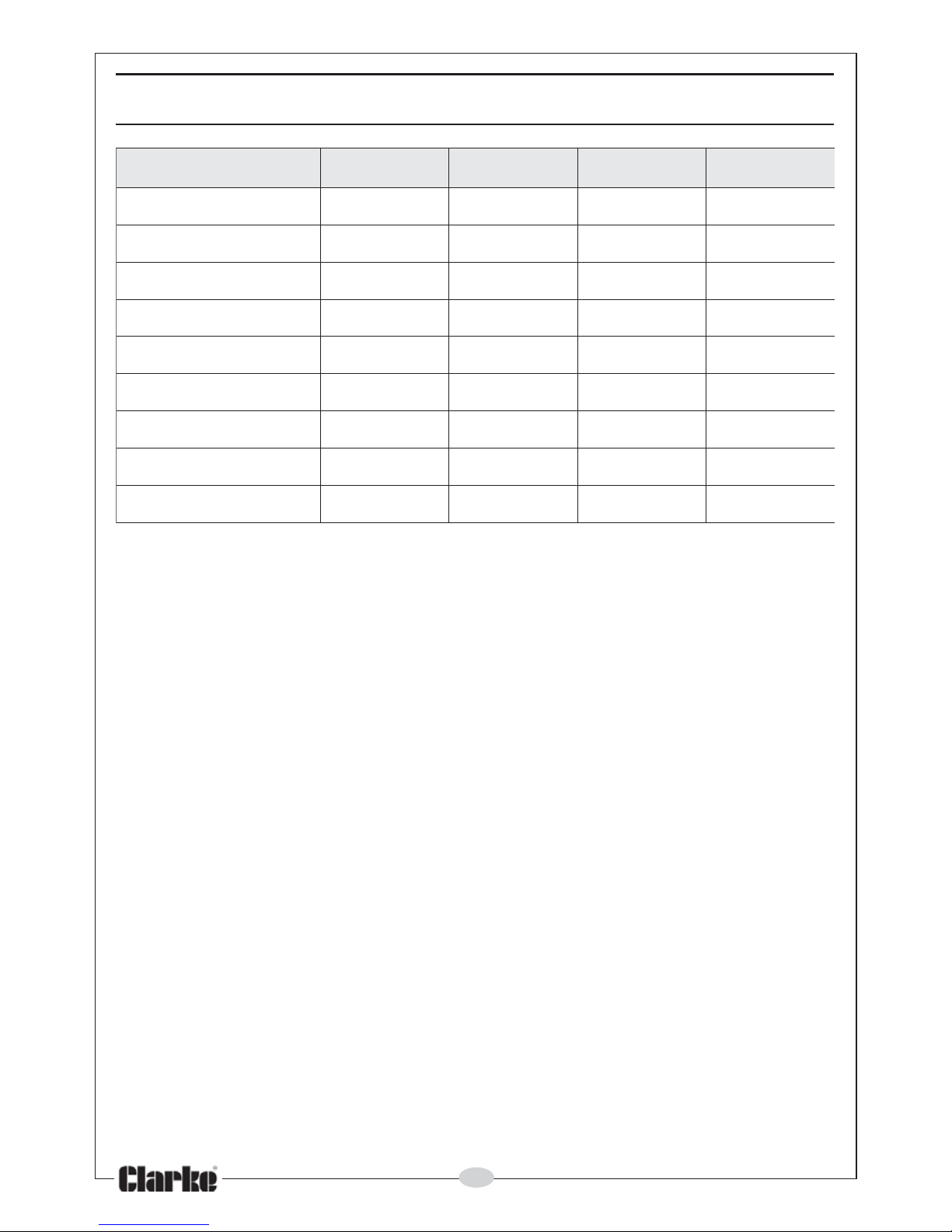
TECHNICAL SPECIFICATION
Please note that the details and specifications contained herein, are correct
at the time of going to print. However, CLARKE International reserve the right
to change specifications at any time without prior notice.
A selection of suitable extension leads & plugs is available from your nearest
CLARKE dealer, for further information, contact your nearest dealer, or
telephone CLARKE International Sales department on 01992 565300.
ledoM P073liveD PS073liveD P173liveD PS173liveD
oNtraP00062965006529601062965106296
thgieWgk6.61gk1.51gk6.61gk1.51
mm)HxWxL(snoisnemiD098x075x094026x01
5x075098x075x094026x015x075
egattaWWK3WK3WK3WK3
egarepmAA5.21A5.21A72.72A72.72
egatloVylppuSzH05/v032zH05/v032zH05/v0
11zH05/v011
gnitaresuFA31A31A23A23
ssalCnoitalusnI02PI02PI02PI02PI
tuptuOtaeH.xaMwk3wk3wk3wk3
Page 11
11
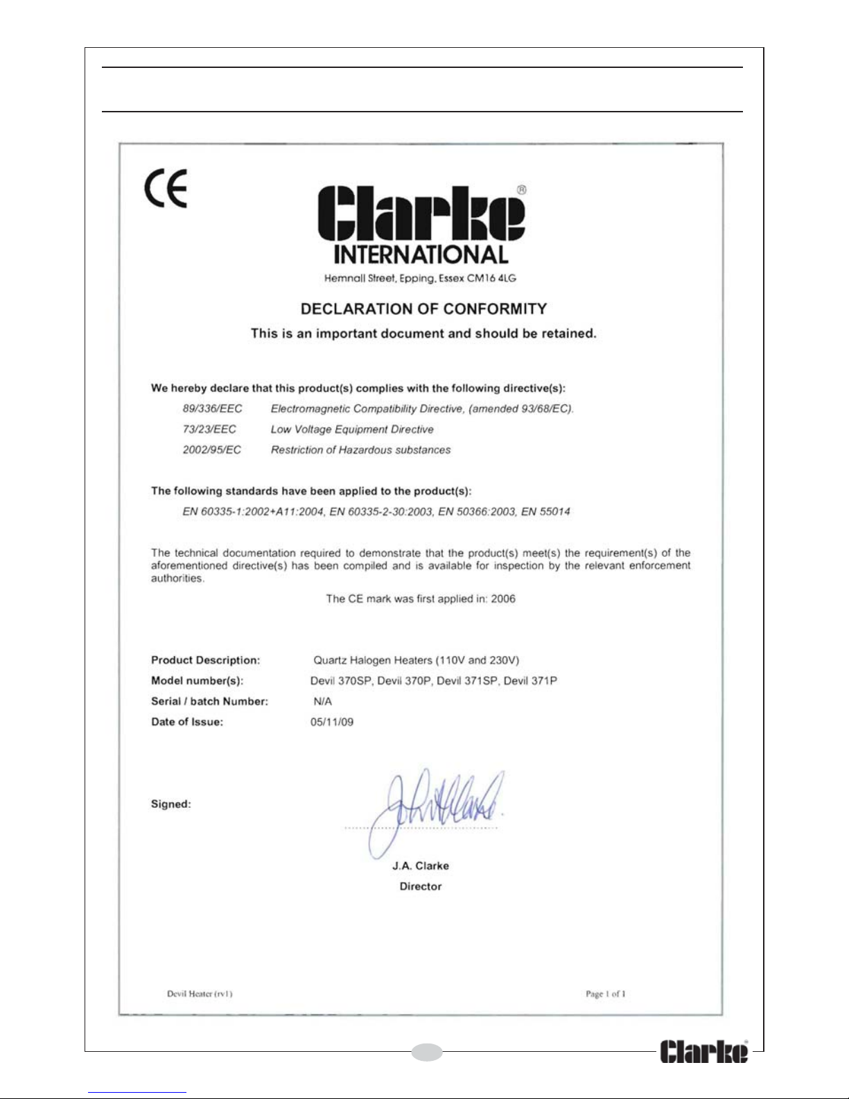
DECLARATION OF CONFORMITY
Page 12

 Loading...