

Page 1
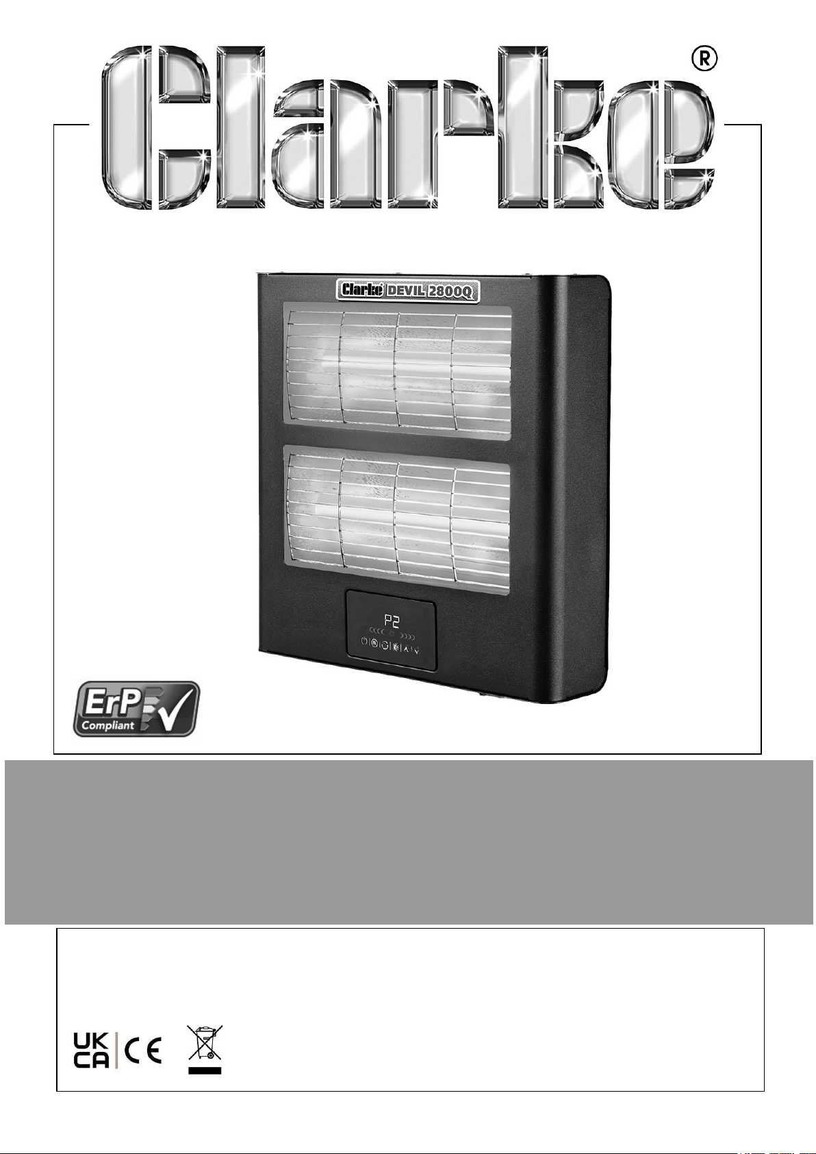
2.8KW DEVIL QUARTZ HALOGEN HEATER
MODEL NO: DEVIL 2800Q
PART NO: 6920334
OPERATING & MAINTENANCE
INSTRUCTIONS
ORIGINAL INSTRUCTIONS DL0925 Rev 3
Page 2
INTRODUCTION
Thank you for purchasing this CLARKE Quartz Halogen Heater.
Before attempting to use this product, please read this manual thoroughly and follow
the instructions carefully. In doing so you will ensure the safety of yourself and that of
others around you, and you can look forward to your purchase giving you long and
satisfactory service.
GUARANTEE
This product is guaranteed against faulty manufacture for a period of 12 months from
the date of purchase. Please keep your receipt which will be required as proof of
purchase.
This guarantee is invalid if the product is found to have been abused or tampered
with in any way, or not used for the purpose for which it was intended. Faulty goods
should be returned to their place of purchase, no product can be returned to us
without prior permission.
This guarantee does not effect your statutory rights.
SPECIFICATIONS
Model Number Devil 2800Q
Part Number 6920334
Weight 5.0kg
Dimensions (W x D x H) 412 x 95 x 420mm
Rated Input Wattage 2.8kW (2 x 1.4kW)
Rated Input Current 12.1A
Supply Voltage 230V/50Hz
Plug Fuse Rating 13A
Ingress Protection Class IP20
Duty Cycle Continuous
Remote Control Batteries 2 x AAA (Not Included)
2
Parts & Service: 020 8988 7400 / E-mail: [email protected] or [email protected]
Page 3
THE FOLLOWING TABLE ADDRESSES THE
INFORMATION REQUIREMENTS OF REG.2024/
1103
Item Symbol Value Unit
Heat output
Nominal heat output P
Minimum heat output (indicative) P
Maximum continuous heat output P
nom
min
max, c
2.8 kW
N/A kW
N/A kW
Auxiliary electricity consumption
In off mode P
In standby mode P
In idle mode P
In network standby P
Seasonal space heating energy efficiency in active mode n
o
sm
idle
nsm
s, on
0.800 W
0.800 W
N/A W
N/A W
91 %
Standby mode with display information or status - No -
Type of heat output/room temperature control (select one)
Single stage heat output, no temperature control No
Two or more manual stages, no temperature control No
With mechanical thermostat temp control No
With electronic temperature control Yes
Electronic temperature control with day timer No
Electronic temperature control with week timer No
Other control options (multiple selections possible)
Room temperature control with presence detection No
Room temperature control with open window detection Yes
Room temperature control with distance control option No
Room temperature control with adaptive start control No
Room temperature control with working time limitation Yes
Room temperature control with black bulb sensor Yes
Room temperature control with self-learning functionality No
Room temperature control with control accuracy No
3
Parts & Service: 020 8988 7400 / E-mail: [email protected] or [email protected]
Page 4
SAFETY RULES
Make sure that you read, understand and comply with the following.
WARNING: THIS PRODUCT IS ONLY SUITABLE FOR WELL
INSULATED AREAS AND IS NOT DESIGNED TO BE THE PRIMARY
HEAT SOURCE.
SAFE WORKING PRACTICES
1. DO NOT operate the heater when you are tired or under the influence of alcohol,
drugs or intoxicating medication.
2. DO NOT stand on the heater.
3. DO NOT use the heater with wet hands or when there is water on the power
cable.
4. Turn the heater off when not in use and keep it in a safe, dry location.
5. The heater is designed to heat enclosed areas, such as workshops and other
industrial areas. DO NOT use the heater for any other function. It is not suitable
for drying clothes or laundry.
ELECTRICAL SAFETY
1. Electrical appliances must match the power outlet. NEVER modify the plug in any
way. DO NOT use adaptor plugs with earthed (grounded) appliances. Correct
plugs and outlets will reduce the risk of electric shock.
2. DO NOT abuse the electrical cable. NEVER use the cable for pulling or
unplugging the heater. Keep the cable away from sources of heat, oil, sharp
edges or moving parts. Damaged or tangled cables increase the risk of electric
shock.
3. Keep the power cable well away from machines and ensure an adequate electrical
supply is close at hand so that the operation is not restricted by the length of the
cable.
4. ALWAYS disconnect from the power supply before moving the heater or
performing any cleaning or maintenance tasks.
5. Inspect the mains cable regularly for signs of damage. DO NOT use if it is
damaged, and ALWAYS keep it away from the source of heat.
6. Check the heater for damage before use. DO NOT use if the heater tubes/
elements are damaged or broken. Any damage should be properly repaired or the
part replaced. If in doubt, DO NOT use. Consult your local CLARKE dealer.
4
Parts & Service: 020 8988 7400 / E-mail: [email protected] or [email protected]
Page 5
POSITIONING
WARNING: DO NOT USE THE HEATER NEAR FLAMMABLE MATERIAL,
LIQUIDS, SOLIDS, GASES OR COMPRESSED GAS CYLINDERS ETC.
1. This heater is designed for indoor use only.
2. DO NOT use this heater in small rooms when they are occupied by persons not
capable of leaving the room on their own unless constant supervision is provided.
3. DO NOT use this heater in the immediate surrounds of a bath, a shower, a
swimming pool or wet surfaces.
4. NEVER place the heater against or near any surface such as a wall, door,
curtains, furniture or combustible material etc. Allow at least 2 metre clearance.
5. DO NOT place the heater immediately below any electrical outlet.
6. DO NOT place the heater on a raised surface or anywhere where it could topple
over. ALWAYS use on a horizontal and stable surface.
7. ALWAYS ensure that the grille cannot be blocked or covered.
8. DO NOT operate fan heaters in explosive atmospheres such as in the presence of
flammable liquids, gasses or dust such as in a paint spray booth or any explosive
environment. Electric motors create sparks which may ignite dust or fumes.
9. This heater can be used by children aged 8 and above and persons with reduced
physical, sensory and mental capabilities or lack of knowledge if they have been
given instruction concerning the use of appliance in a safe way and understand
the hazards.
10. Children less than 3years should be kept away unless continuously supervised.
11. Children should NOT play with this appliance.
OPERATION
1. CAUTION: Some parts of this product can become very hot and cause burns.
Particular attention should be given where children, vulnerable people and animals
are present.
2. The heater must only be used by people who have read these instructions and
have been trained in its use.
3. DO NOT use if dropped.
4. DO NOT use if there is visible signs of damage.
5. DO NOT obstruct the air inlet and outlet sections of the heater.
6. DO NOT cover the heater with anything that could restrict the air flow.
5
Parts & Service: 020 8988 7400 / E-mail: [email protected] or [email protected]
Page 6
7. DO NOT touch the heater casing or grille when first switched off, as these will be
very hot and will take time to cool.
8. DO NOT get the heater wet or use in areas of high condensation.
9. DO NOT connect other appliances to the same mains socket as the heater.
10. DO NOT use this heater with a programmable timer used to switch it on
automatically.
11. DO NOT leave the heater unattended.
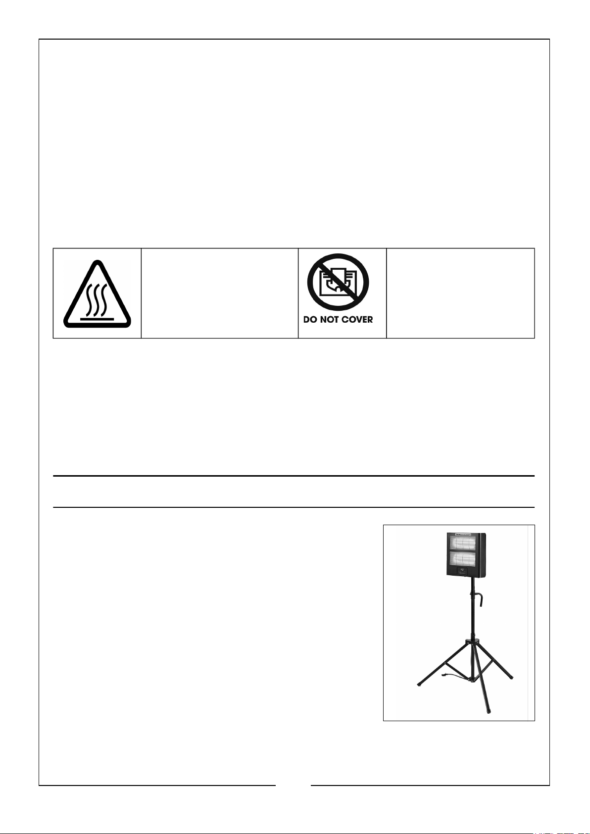
SAFETY SYMBOLS
These safety symbols appear on the heater.
CAUTION: Hot Surface,
DO NOT Touch
DO NOT Cover
SERVICE & REPAIRS
• If necessary, have your heater repaired by a qualified person using
identical replacement parts, or contact the CLARKE Service Department.
This will ensure that the safety of the product is maintained.
Please keep these instructions in a safe place for future reference.
CLARKE ACCESSORIES
This heater unit, as well as being wall mounted, can also
be mounted on a free standing tripod. This tripod can be
purchased from any CLARKE stockists.
• Model: Tripod for Devil 1200Q & Devil 2800Q
Quartz Infrared Heaters, product number:
6920335
6
Parts & Service: 020 8988 7400 / E-mail: [email protected] or [email protected]
Page 7
ELECTRICAL CONNECTIONS
Plug must be BS1363/A approved.
WARNING: READ THESE ELECTRICAL SAFETY INSTRUCTIONS
THOROUGHLY BEFORE CONNECTING THE PRODUCT TO THE POWER
SUPPLY.
The 230V models are provided with a 13 amp BS 1363 plug, fitted with a 13 amp fuse
and MUST be connected to a standard, 230 Volt (50Hz) electrical supply, preferably
through a suitably fused isolator switch.
If the plug has to be changed because it is not suitable for your socket or because of
damage, it must be removed and a replacement fitted, following the wiring
instructions shown below. The old plug must be discarded safely as insertion into a
power socket could cause an electrical hazard.
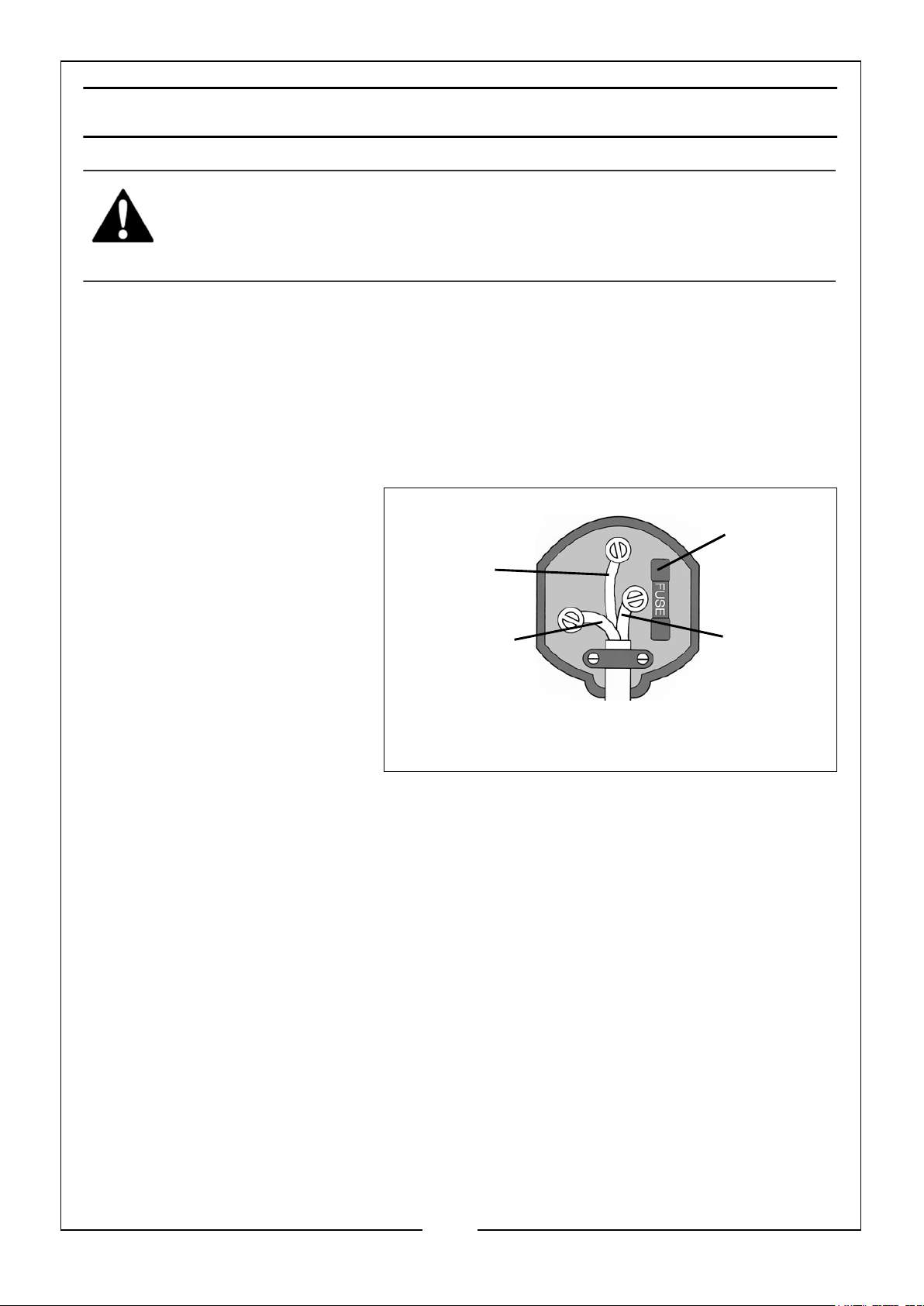
The wires in the mains lead
should be wired up in
accordance with the following
colour code:
• Connect the GREEN &
YELLOW wire to the plug
terminal marked with a
letter E.
Earth
(Green and
Yellow)
Neutral
(Blue)
Always fit
a 13 Amp
fuse.
Live
(Brown)
• Connect the BROWN
wire to the plug terminal
marked a letter “L”.
• Connect the BLUE wire to the plug terminal marked a letter “N”.
The fuse in the plug must be replaced with one of the same rating and this
replacement must be ASTA approved to BS1362.
We strongly recommend that this machine is connected to the mains supply via a
Residual Current Device (RCD).
If in any doubt, consult a qualified electrician. DO NOT attempt any electrical repairs
yourself.
Ensure that the outer sheath of
the cable is firmly held by the clamp
Parts & Service: 020 8988 7400 / E-mail: [email protected] or [email protected]
7
Page 8
UNPACKING AND ASSEMBLY
UNPACKING
Before assembling, please check contents against the following list and advise your
dealer immediately if any parts are missing.
1 x Heater
1 x 2 Piece Wall Support Bracket and 4 Screws
1 x Remote Control Unit (Batteries not included)
WALL MOUNTING ASSEMBLY
WARNING: LOCATE THE UNIT NO CLOSER THAN 0.3M TO THE
CEILING, NO LESS THAN 1.8M FROM THE FLOOR AND NO LESS THAN
1M FROM ANY SIDEWALL. ENSURE THE MOUNTING SURFACE IS
SUITABLE AND STRONG ENOUGH TO SECURELY AND SAFELY
MOUNT THE UNIT (FIXINGS NOT SUPPLIED).
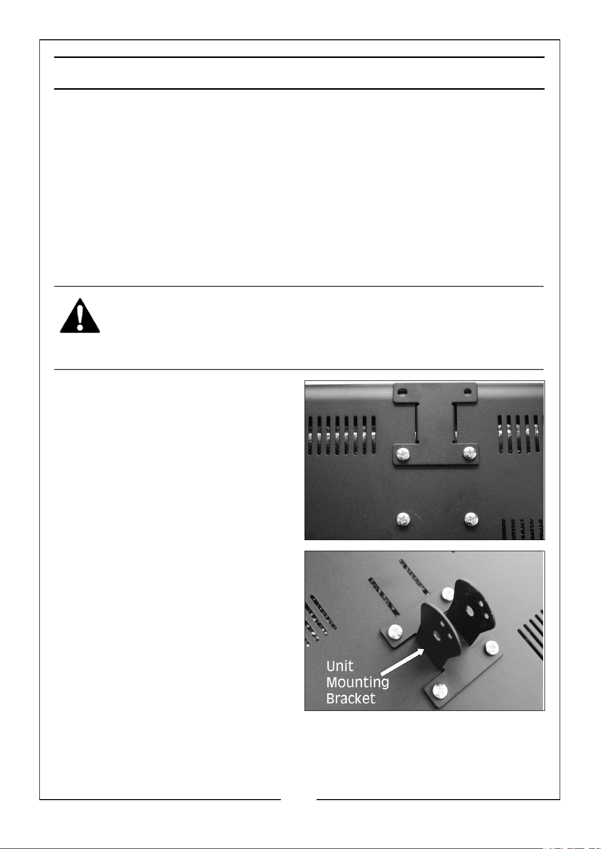
1. Remove the four screws on the rear of
the unit and take out the unit
mounting bracket.
2. Use the 4 screws to attach the unit
mounting bracket to the rear of the
unit as shown.
NOTE: Make sure its orientation is
correct in order to facilitate
downward adjustment of the
unit when fitted to the wall
mounting bracket.
3. Ensure all fixings are firmly and
securely attached.
8
Parts & Service: 020 8988 7400 / E-mail: [email protected] or [email protected]
Page 9
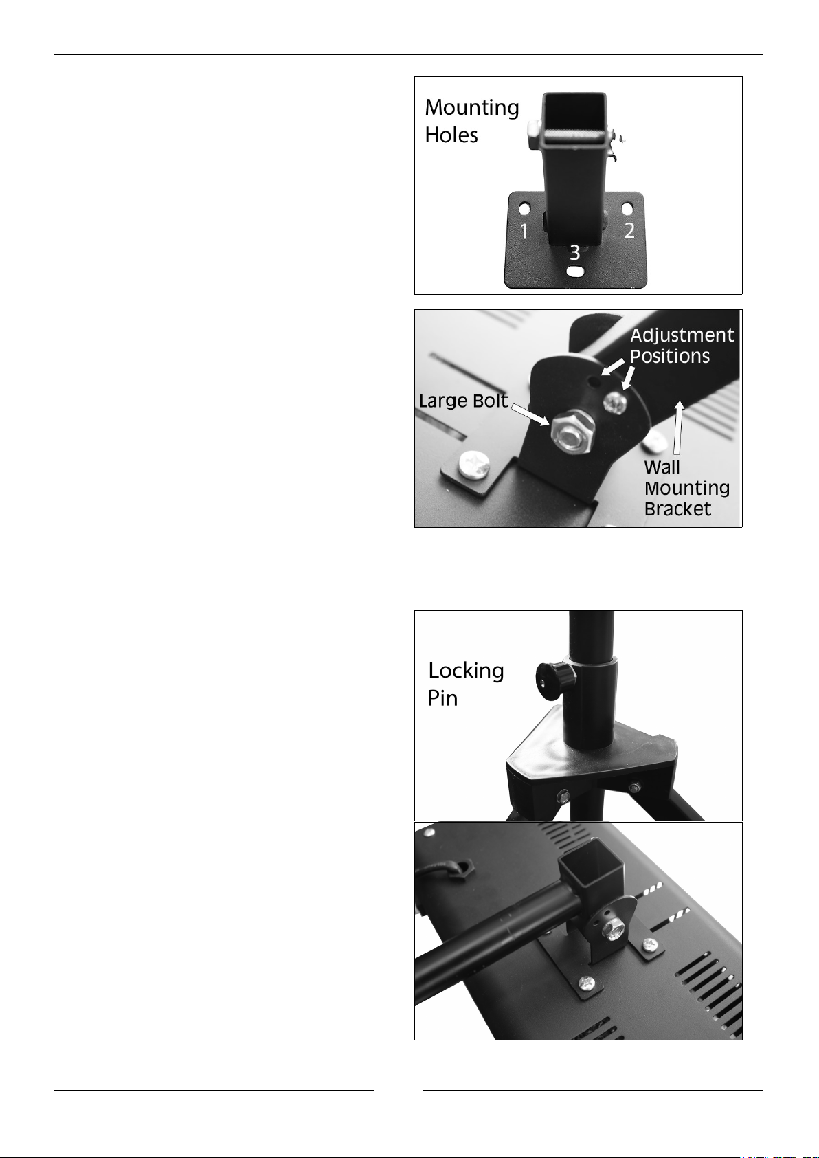
4. Mount the wall mounting bracket to a
suitable wall via the 3 mounting holes
as shown and suitable fixings (not
supplied).
NOTE: No closer than 0.3m to the
ceiling, 1.8m from the floor and
1m from any side walls.
5. Remove the large bolt and small
screw from the wall mounting bracket.
Slide the wall mounting bracket
between the unit mounting bracket
arms and secure with the large bolt.
Adjust the unit so that the small screw
holes (2 positions available) align and
screw in the small screw to secure the
unit at the angle required.
IF USING THE TRIPOD (SOLD SEPARATELY)
1. Undertake points 1 - 3 of the Wall Mounting Assembly.
2. Pull out the locking pin and extend the
legs as far as possible until the locking
pin fits in the lower locking hole.
NOTE: DO NOT use if pin does not
lock into place in the lower
locking hole
3. Using the large bolt that is supplied
with the wall mounting bracket, attach
the tripod mounting bracket to the
unit mounting bracket as shown.
9
Parts & Service: 020 8988 7400 / E-mail: [email protected] or [email protected]
Page 10
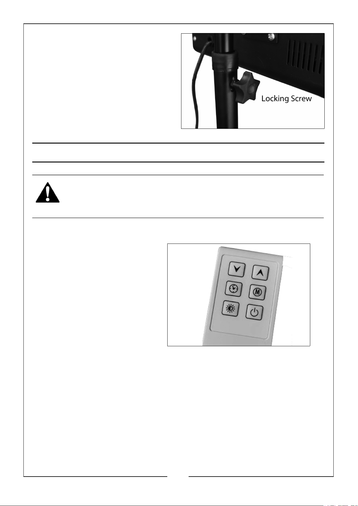
4. Place the tripod mounting bracket into
the top of the tripod and tighten in
place using the locking screw.
OPERATION
WARNING: FOR SAFE OPERATION OF THIS HEATER IT IS
ESSENTIAL TO READ THESE INSTRUCTIONS BEFORE USE.
USING THE REMOTE CONTROL
• 2 x AAA batteries (not
included) are required and are
installed as shown by the
diagram found inside the
control unit.
• The remote control must be
directed at the heater display
panel. It has a range of approx
2.5 metres and must be aimed
at the correct angle.
• The function of each button on
the remote control are the same as shown on the operation panel on the
front of the heater.
MANUAL OPERATION
1. Mount the heater on a wall or tripod and following all safety precautions and
assembly instructions, connect to a suitable power supply.
10
Parts & Service: 020 8988 7400 / E-mail: [email protected] or [email protected]
Page 11
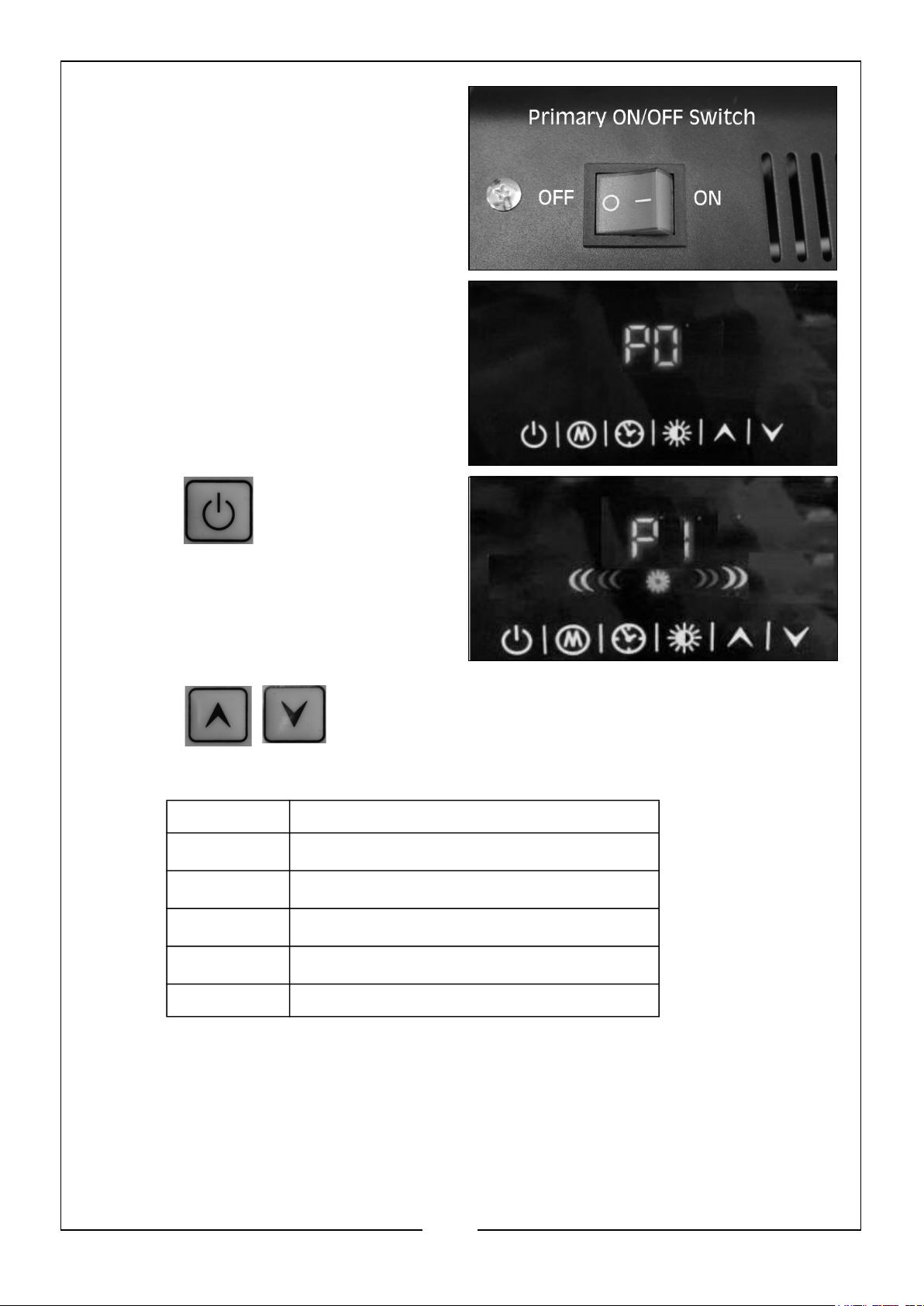
2. Switch on the power at the ON/OFF
switch.
3. The heater will be in Standby with the
display showing PO.
4. Press to turn on the upper
heating lamp and the screen will show
P1.
5. Press to select the mode from P1-P6, referring to the different
temperature settings.
P1 Only the upper element will work
P2
P3
P4
P5
24oC
26oC
28oC
30oC
P6 Both elements will work
• During mode P2-P5 the upper element is working all the time and the
lower element will be turned off automatically according to the set
temperature.
11
Parts & Service: 020 8988 7400 / E-mail: [email protected] or [email protected]
Page 12
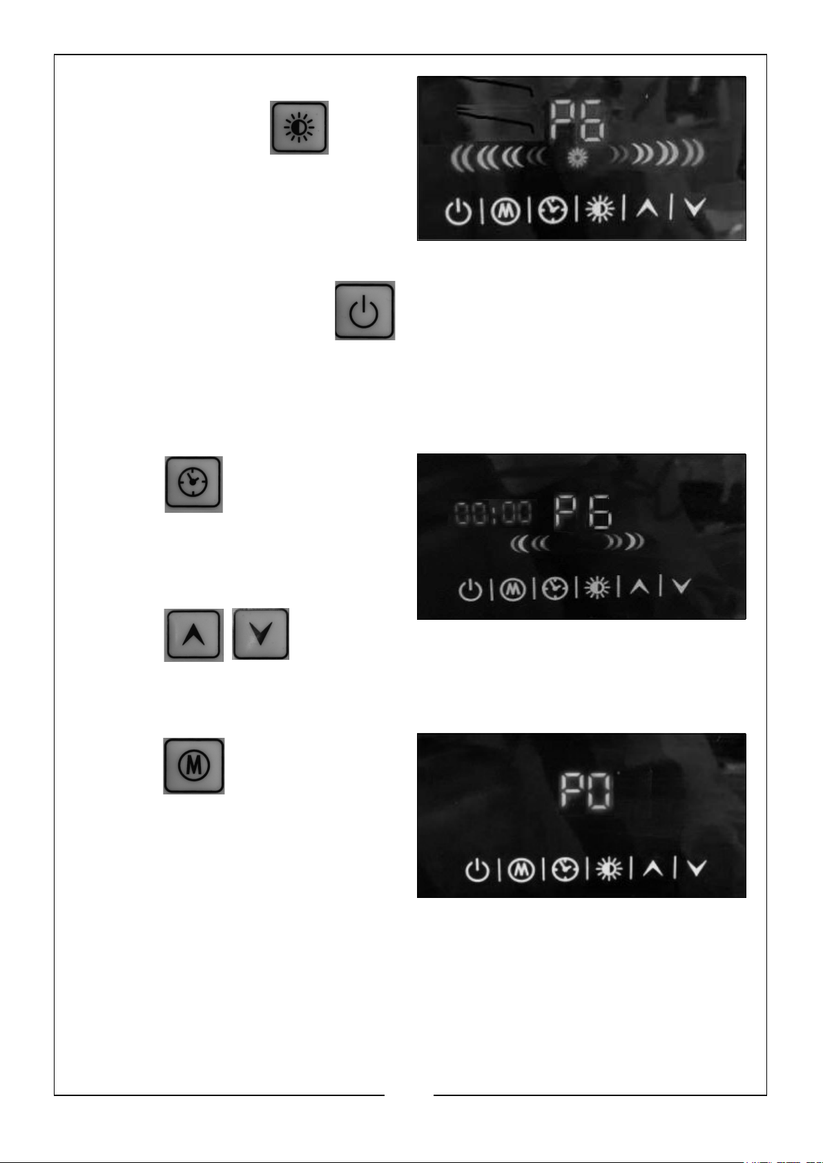
6. The user can change from mode P1
and P6 by pressing . The
screen will show a cascade effect
when in mode P6.
7. To power off the unit, press again. The heater stops working and returns
to standby with the screen showing ‘PO’.
8. Switch off the ON/OFF switch and unplug the heater.
SETTING THE SHUTDOWN TIMER
1. Press to set the shutdown
timer.
• The time on the screen flickers with
initial status 00:00.
2. Press to set the time
to turn the heater off.
• It increases/decreases 1 hour per press.
3. Press when you finish setting
the time required and the heater will
set to countdown mode.
4. When the time is up, the heater turns
off automatically and enters the
standby state P0.
FUNCTION FOR DETECTING OPENING WINDOWS
1. When the ambient temperature drops by 5oC within 10 minutes, the heater will
turn off automatically and enter a standby state with three alarm beeps.
12
Parts & Service: 020 8988 7400 / E-mail: [email protected] or [email protected]
Page 13
• Users need to turn on the heater manually by pressing or the
primary ON/OFF switch.
CLEANING & MAINTENANCE
WARNING: IF THE HEATER HAS BEEN USED, ALWAYS ALLOW IT TO COOL
DOWN FOR AT LEAST 15 MINUTES AND DISCONNECT FROM THE POWER
SUPPLY BEFORE PERFORMING ANY MAINTENANCE TASKS.
FITTING/REPLACING TUBES
Before attempting to fit/replace halogen tubes, make sure that the heater is switched
off and isolated from the electrical supply by removing the plug from the socket.
NEVER handle the halogen tubes with bare hands. Always handle using either a soft
clean glove or a piece of soft clean cloth wrapped around the lamp.
1. Loosen and remove the retaining screws on the top and bottom of the unit
securing the front cover, remove the guard and store removed parts safely.
2. To remove the tube, grasp and gently but firmly push it to one end of the heater.
The tube holders are spring loaded and will allow the tube sufficient movement to
clear the opposite holder.
3. Remove the tube and dispose of it according to local regulations.
4. Fit new halogen tube in reverse order.
5. Replace the guard and cover using the screws removed earlier.
6. Make sure all fixings are secure and tight.
PERIODICALLY
1. If there is any serious build up of dirt, wipe the exterior thoroughly with a damp
cloth. Take care that no moisture enters the heater. Take care NOT to touch the
tubes with your fingers.
2. Inspect the power cable for damage. Undue heat will cause the cable to stiffen
and crack. If this is found, have the cable replaced. Check cable routing and
ensure it is well away from the heat source.
3. Ensure heating tube is clear of dust (use compressed air to clean if possible,
ALWAYS wear a dust mask and safety glasses if performing this operation).
4. Refer to your CLARKE dealer if internal repair is required.
5. When storing the heater, allow it to cool down, then place it in its packing box for
storage in a dry, ventilated place.
13
Parts & Service: 020 8988 7400 / E-mail: [email protected] or [email protected]
Page 14
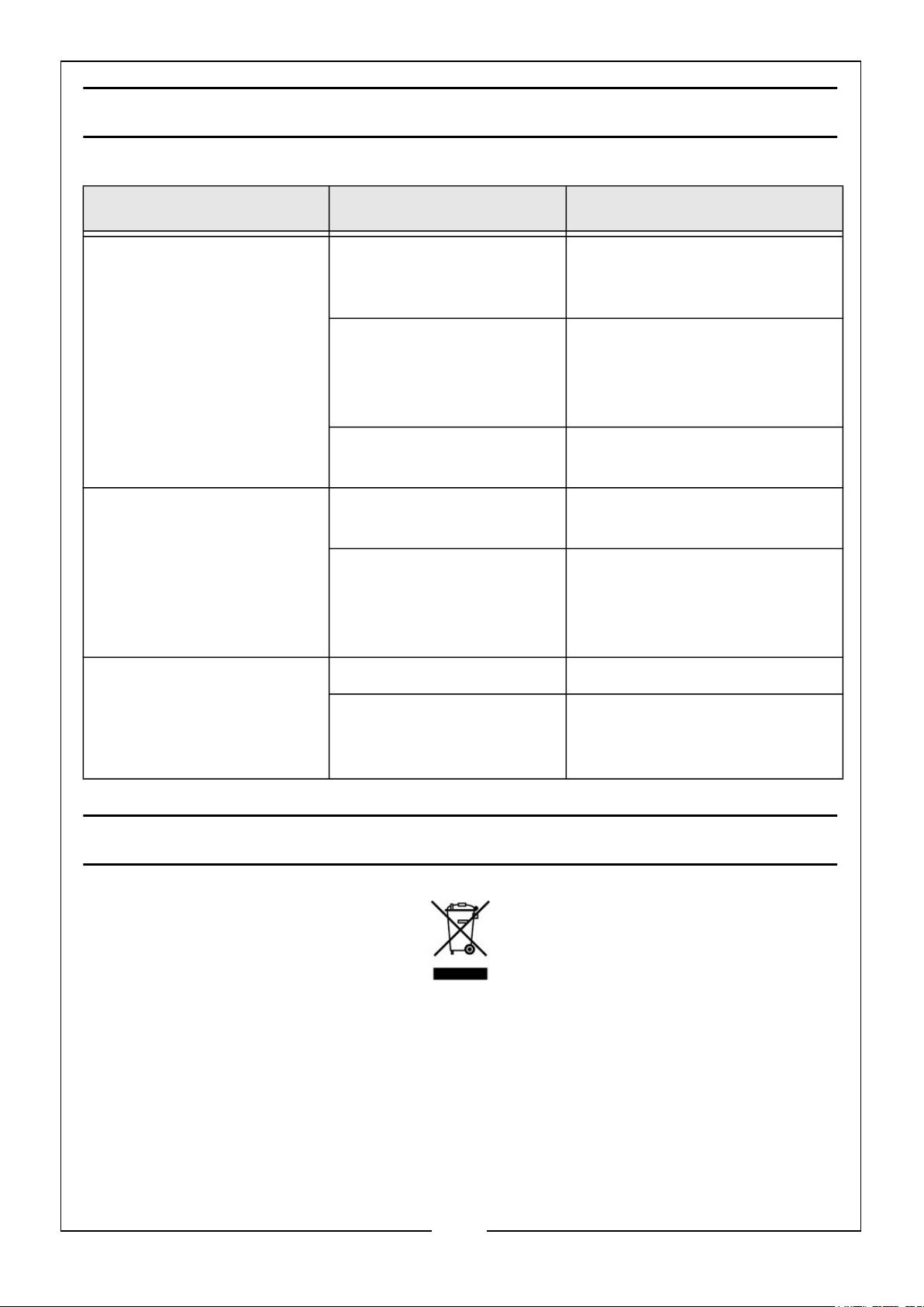
FAULT FINDING
SYMPTOM PROBLEM SOLUTION
Heater does not operate, although plugged in
and switched on.
Heater tube is glowing
hot.
Heater does not respond
to remote controller.
Plug is loose/bad connection.
Fuse blown. Replace if necessary and
No power at socket outlet.
Input voltage incorrect. Ensure power supply matches
Air supply partly blocked. Ensure the heater is kept
Batteries defective. Replace batteries.
Controller is out of range
or not pointing at the display panel.
Remove the plug & check the
connection of the plug and
socket.
investigate the cause. If fuse
blows repeatedly, consult
your CLARKE dealer.
Insert plug into a suitable
socket.
the rating on the label.
away from any objects or
materials which could impair
the fresh air supply.
Move closer or try different
angles of pointing the controller at the heater.
ENVIRONMENTAL RECYCLING POLICY
Through purchase of this product, the customer is taking on the obligation to deal
with the WEEE in accordance with the WEEE regulations in relation to the treatment,
recycling & recovery and environmentally sound disposal of the WEEE.
In effect, this means that this product must not be discarded with general household
waste. It must be discarded according to the laws governing Waste Electrical and
Electronic Equipment (WEEE) at a recognised disposal facility.
14
Parts & Service: 020 8988 7400 / E-mail: [email protected] or [email protected]
Page 15
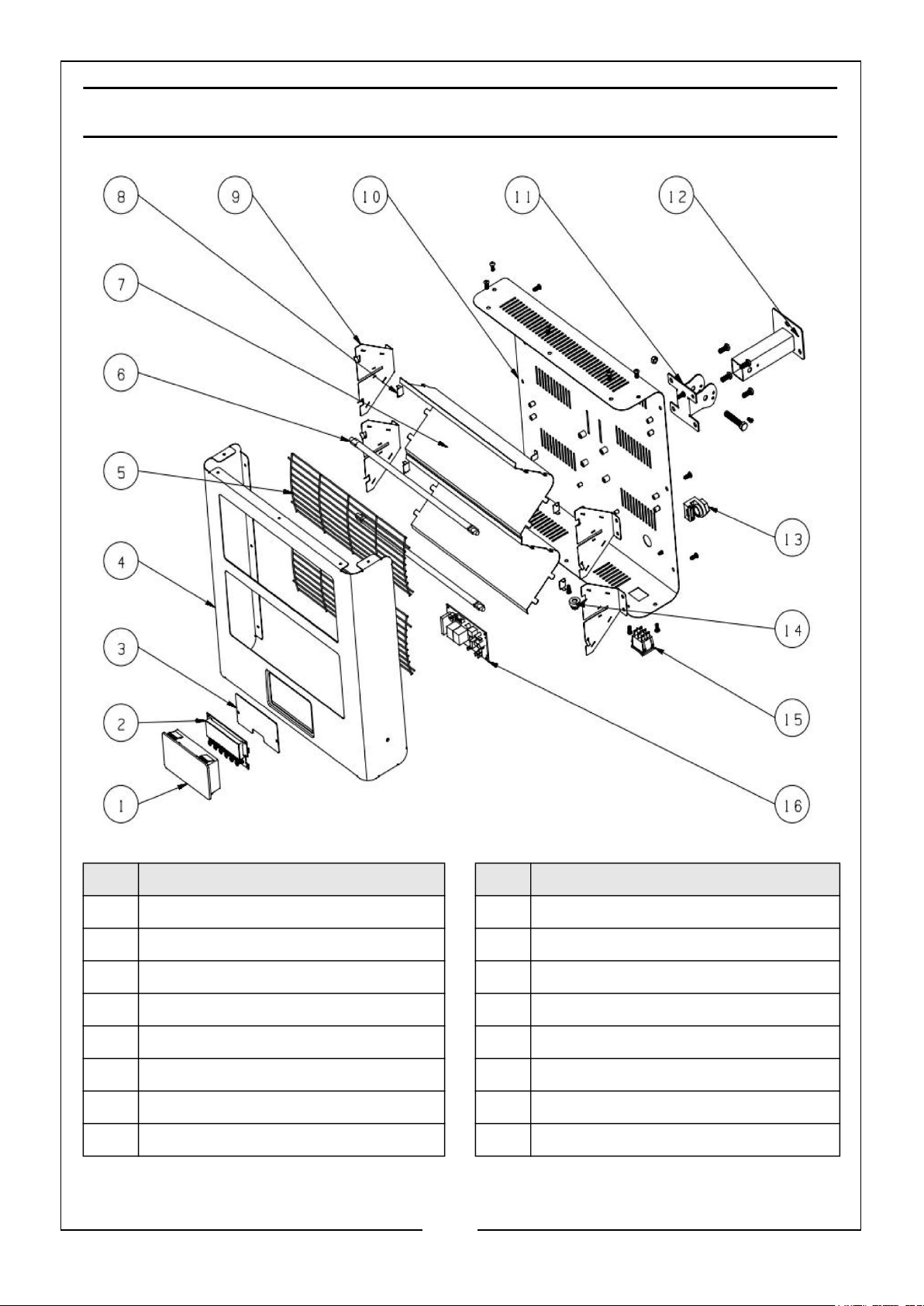
PARTS DIAGRAM
No Description No Description
1 Manual Operation Panel Cover 9 Reflector Side Plate
2 ERP Manual Operation Panel PCB 10 Back Case
3 PCB Box Plate 11 Support Bracket
4 Front Case 12 Wall Mounting Bracket
5 Front Grille 13 Cable Gland
6 230V 1400W Heating Element 14 Rubber Sleeve
7 Reflector 15 Rocker switch
8 Reflector Bracket 16 Power PCB & Battery
15
Parts & Service: 020 8988 7400 / E-mail: [email protected] or [email protected]
Page 16
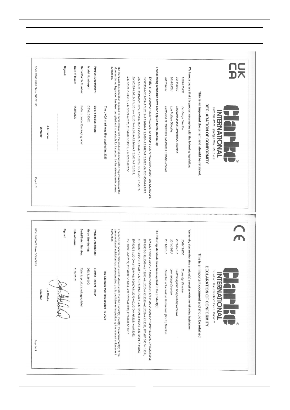
DECLARATION OF CONFORMITY
16
Parts & Service: 020 8988 7400 / E-mail: [email protected] or [email protected]
 Loading...