

Page 1
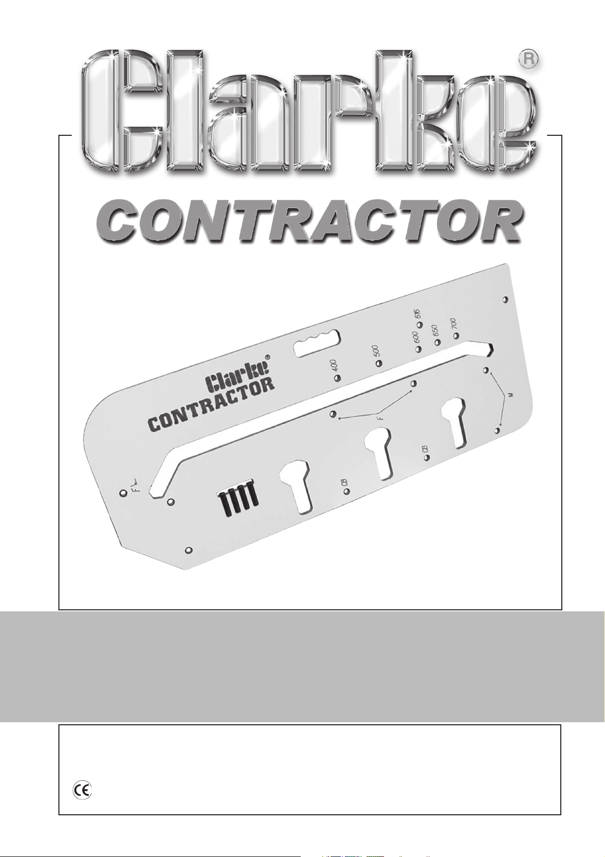
WORKTOP JIG
WORKTOP JIG
Model No: CWJ700/CWJ900
Part No: 6462118/6462119
OPERATION & MAINTENANCE
INSTRUCTIONS
0305
Page 2

Please note that the details and specifications contained herein, are correct at the time of going
to print. However, CLARKE International reserve the right to change specifications at any time
without prior notice.
-1-
Page 3
Thank you for purchasing this CLARKE Worktop Jig.
Before attempting to use the jig, please read this manual thoroughly and follow the
instructions carefully. In doing so you will ensure the safety of yourself and that of others
around you, and you can look forward to the jig giving you long and satisfactory service.
CLARKE GUARANTEE
This CLARKE product is guaranteed against faulty manufacture for a period of 12
months from the date of purchase. Please keep your receipt as proof of purchase.
This guarantee is invalid if the product is found to have been abused or tampered
with in any way, or not used for the purpose for which it was intended.
Faulty goods should be returned to their place of purchase, no product can be
returned to us without prior permission.
This guarantee does not effect your statutory rights.
Specifications
Model Nos: ............................... CWJ700 & CWJ900
Part Nos: ................................... 6462118 & 6462119
Worktop Jig
For cutting left and right standard 90º and 45º joints.
For cutting connecting bolt recesses.
Cuts worktops ranging from 400mm to 900mm wide (model dependant).
Integral carry handle.
Snap in peg storage holder, includes 3 pegs.
Replacement pegs available from your Clarke dealer.
Part No:WTJIG-01-PEGS-BK
Tools required (not supplied) for use with the worktop jig
12mm (½”) router capable of holding a 30mm guide bush.
30mm guide bush.
½” tungsten carbide router bit.
Minimum of two quick action woodworking clamps.
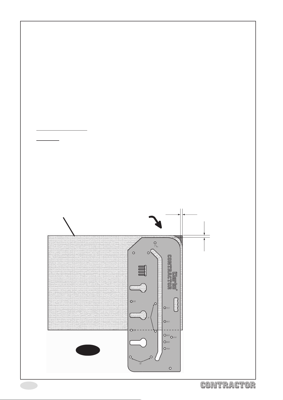
NOTE: worktop corners can be shaped using one of the four corners of the jig as a
template, there are three radii (10mm, 50mm & 100mm) the fourth corner is
45º. Example shown on page 17.
Tip: wherever possible, ALWAYS cut the joint before cutting wortop to length, this allows
for rectifiication in the event of minor mistakes when cutting the joint.
-2-
Page 4
Safety Precautions
WARNING:
As with all machinery, there are certain hazards involved with their operation and
use. Exercising respect and caution will considerably reduce the risk of personal
injury. However, if normal safety precautions are overlooked or ignored, personal
injury to the operator or damage to property, may result.
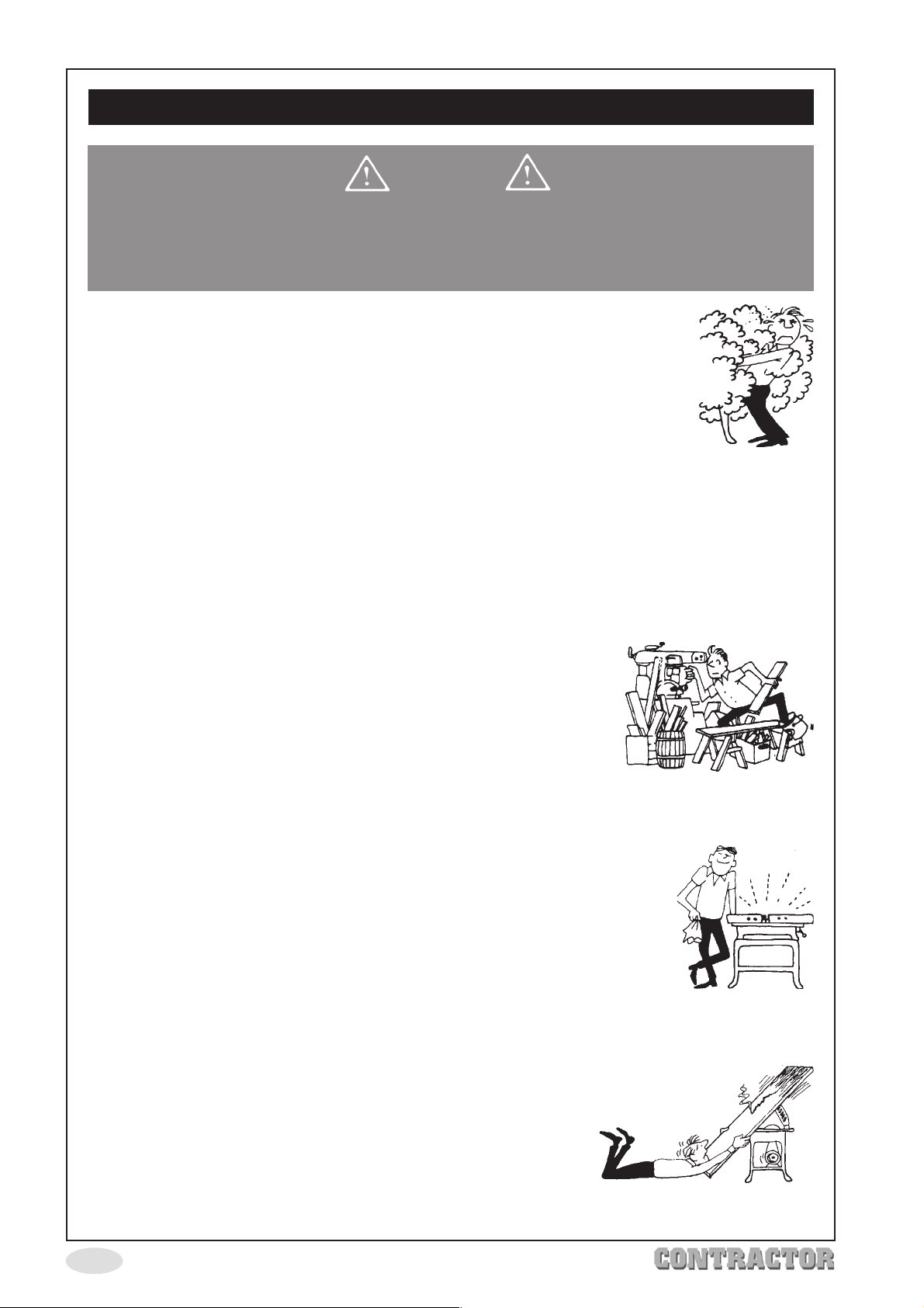
1. ALWAYS Learn the equipments applications, limitations and any
specific potential hazards peculiar to it. Read and become familiar
with the entire operating manual.
2. ALWAYS use a face or dust mask if operation is particularly dusty.
3. ALWAYS check for damage. Before using tools and equipment, any
damaged should be checked to ensure that it will operate properly,
and perform its intended function. Check for alignment of moving
parts, breakage of parts, mountings and any other condition that may affect the
equipments operation. Any damage should be properly repaired or the part replaced.
If in doubt, DO NOT use. Consult expert advice.
4. ALWAYS disconnect power tools from the electric supply before servicing and when
making adjustments or changing accessories etc.
5. ALWAYS wear safety goggles, manufactured to the latest European Safety Standards.
Everyday eyeglasses do not have impact resistant lenses, they are not safety glasses.
6. ALWAYS keep work area clean. Cluttered areas and benches
invite accidents.
7. ALWAYS ensure that adequate lighting is available. A
minimum intensity of 300 lux should be provided. Ensure that
lighting is placed so that you will not be working in your own
shadow.
8. ALWAYS keep children away. All visitors should be kept a safe distance from the work
area, especially whilst working with tools particularly power tools.
9. ALWAYS maintain equipment in top condition. Keep tools/machines
clean for the best and safest performance. Follow maintenance
instructions.
10. ALWAYS handle with extreme care. Do not carry tools/machines
by the electric cable, or yank the cable to disconnect it from the
power supply.
11. ALWAYS ensure the switch is off before plugging in to mains. Avoid
accidental starting.
12. ALWAYS concentrate on the job in hand, no matter how trivial it may seem. Be aware
that accidents are caused by carelessness due to familiarity.
13. ALWAYS keep your proper footing and balance at all times,
don’t overreach. For best footing, wear rubber soled
footwear. Keep floor clear of oil, scrap wood etc.
14. ALWAYS seek assistance when lifting heavy objects
(worktops etc).
-3-
Page 5
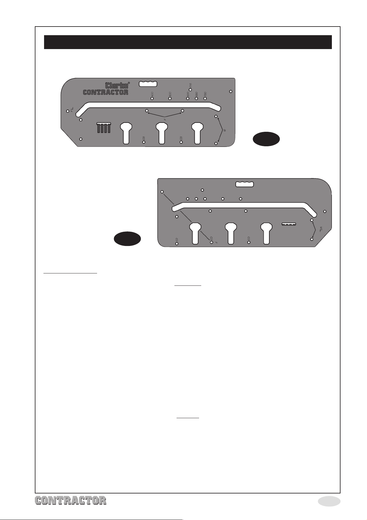
Using The Jig
Rear View
Front View
Fig. 1
Fig. 2
Before Starting:
ALWAYS
ensure the worktop is firmly supported on trestles or similar.
ensure the jig is firmly secured to the worktop using no less than 2 quick
woodworking clamps or similar.
ensure there are no obstructions in the path of the router, also the router cutter
beneath the worktop, i.e. the cutter doesn’t cut into the bench/trestle when cutting
through the worktop.
use only good quality sharp tungsten router bits.
cut into the post form edge (curved edge) of the worktop to avoid break out or
chipping of the laminate.
keep the router vertical to the jig and laminate.
keep the jig surface clean.
NEVER
exceed 10mm depth of cut in one pass.
remove or position the router whilst the cutter is still rotating.
PLEASE NOTE: for illustrative purposes only, all diagrams and instructions in this manual
make reference to 700mm worktops, but apply equally to all sizes of worktop ranging
from 400mm to 900mm
-4-
Page 6
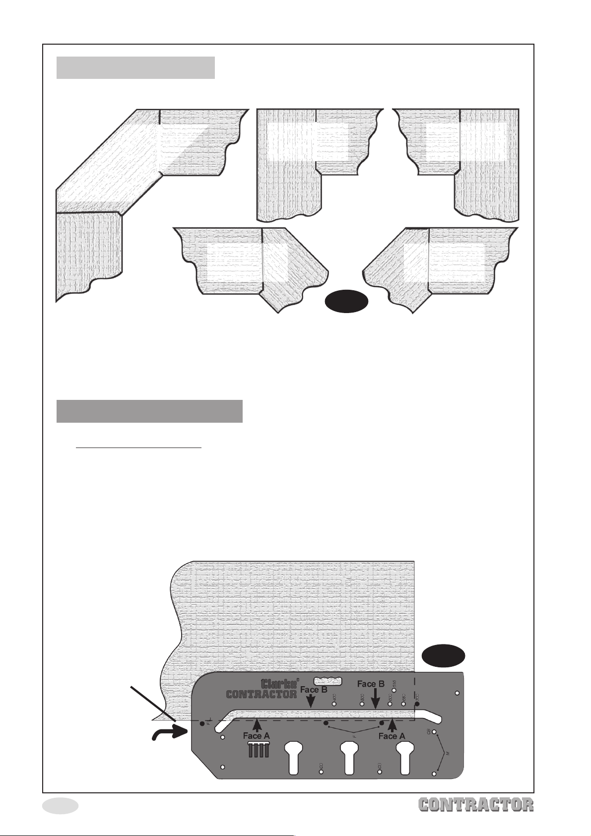
Standard Joints
Corner joint
using left
and
right 45º joints
90º Left
Hand Joint
45º Right
Hand Joint
90º Right
Hand Joint
45º Left
Hand Joint
Fig. 3
Before commencing, prepare the router by removing the fence guide etc if fitted, attach
the 30mm guide bush and if available, a dust extractor, also install the cutter. Put the
router safely to one side until ready to use.
Left Hand 90º Joints
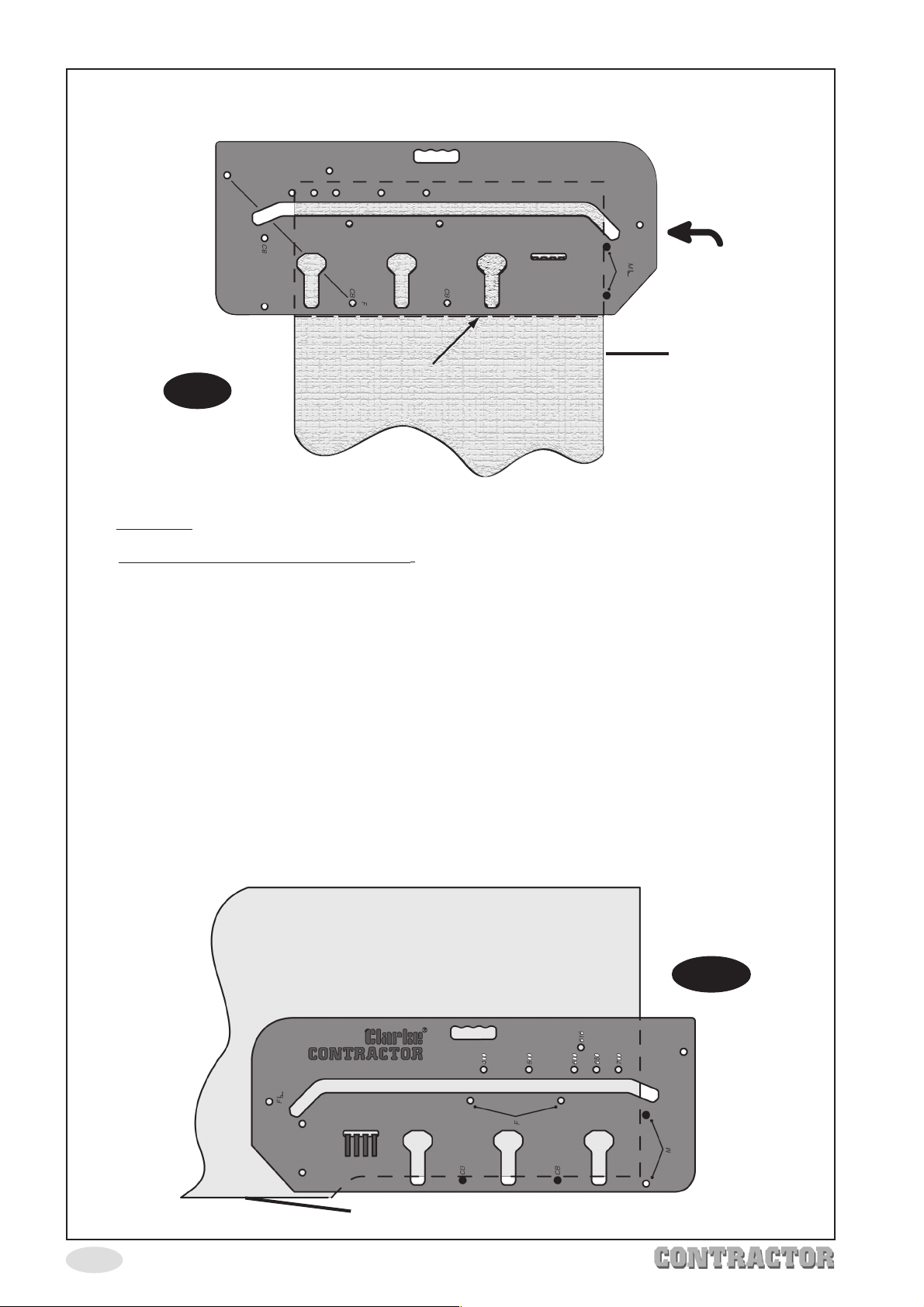
1. Female joint (Fig. 4) - prepare the worktop with laminate face up and the post
form (curved edge) towards you.
2. Fully insert three pins in the holes marked
3.Fully insert fourth pin in the hole corresponding to the worktop width (e.g.700mm).
NOTE: when inserting pins, ensure the heads finish up below the jig surface,
otherwise the router will not sit flat on the jig resulting in ill fitting joints.
Female joint - laminate face up.
‘F’.
Fig. 4
Post Form Edge
-5-
Cut Direction
Page 7
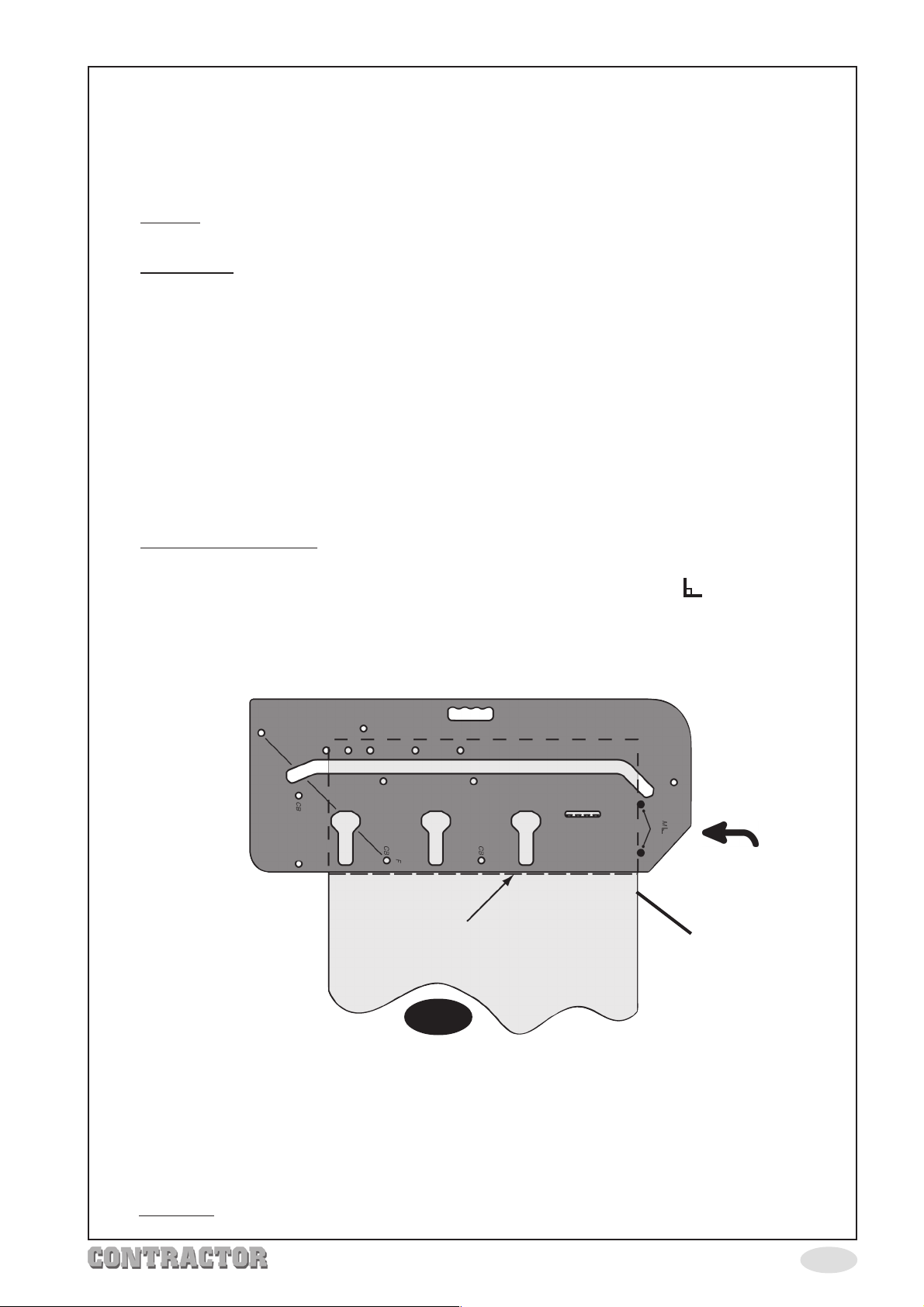
4. Ensure the 3 pins in holes
fourth pin in the hole marked with the worktop width is pushed firmly against the worktop
edge.
5. Firmly clamp the jig onto the worktop ensuring the clamps do not obstruct the router
path.
6.
Cutting-Position the router (guide bush) in the jig slot at the post form end, ensure the
router base is flush on the jig surface. Set the cut depth to 10mm max.
7.
IMPORTANT: Ensure the router is pulled towards the slot edge nearest you (Face ‘A’
Fig.4). Switch the router ON and slowly move it, held firmly against face A, until the
far end of the workpiece is reached. Switch OFF and wait for the cutter to stop
spinning.
8. Lift the router out off the slot and return it to the start position again, increase the
depth of cut a further 10mm and make a second pass. Keep repeating steps 7 & 8
until the cut is complete, i.e. the cutter is below the bottom of the worktop.
9. Switch the router OFF and wait for it to stop spinning, return the router to the start
position again. Switch ON, this time, push the router against the slot edge furthest
from you (Face ‘B’, Fig.4) and make one finishing cut AT FULL DEPTH. When finished,
switch OFF and wait for the cutter to stop spinning, remove the router and jig, store
them away safely for reuse.
10.
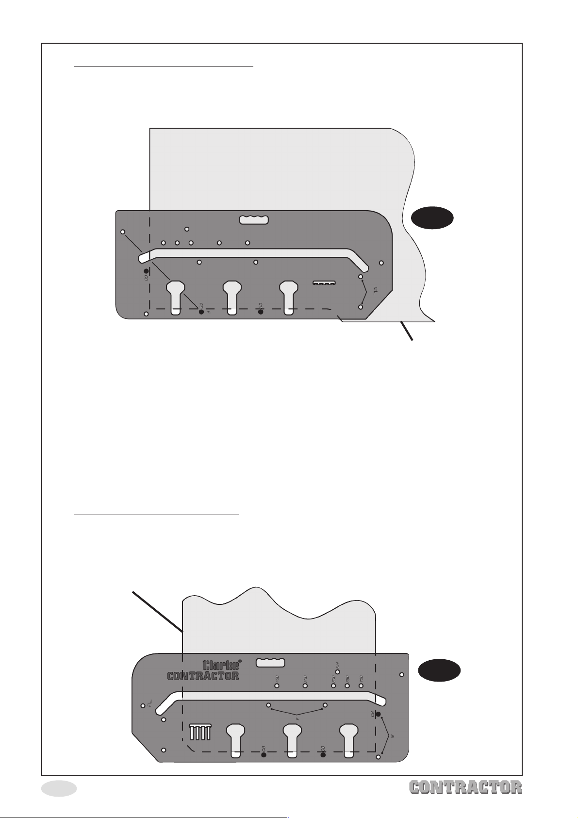
Male Joint (Fig. 5) - Place the worktop with the laminate face down, taking care
to protect the surface.
‘F’
are pushed firmly against the post formed edge, and the
‘M’
11. Fully insert two pins in the jig holes marked
12. Refer to page 10, (cutting to length) to determine where to mark the pencil line for
positioning the jig on the worktop.
Pencil Line
Male Joint - Laminate face down.
with angle symbol .
Cut Direction
Post Form Edge
Fig. 5
13. Ensure the two pins in holes
the jig lined up on the pencil line as above (Fig. 5).
14. Firmly clamp the jig to the worktop ensuring it doesn’t move as you do so. Ensure the
clamps do not obstruct the router path.
15.
Cutting - follow steps 6 - 9 above.
‘M’
are pushed firmly against the post form edge and
-6-
Page 8
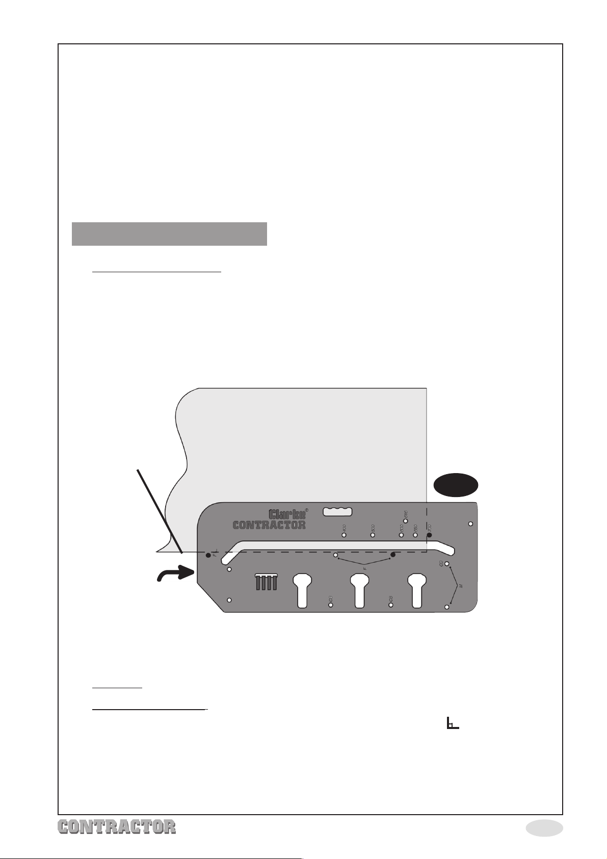
16. Female Bolt Recesses (Fig. 6) - Place the worktop with the laminate face down.
17. Fully insert three pins in holes marked
18. Clamp the jig to the worktop ensuring the three pins are firmly pushed up to the cut
out face and the worktop edge. Ensure clamps do not obstruct the router path.
Female bolt recesses - Laminate face down.
‘CB’.
Fig. 6
Post Form Edge
19. Place the router into the front of one of the clamp bolt recesses, set the depth of
cut to 10mm max. Switch the router ON and machine the recess. When done,
switch the router OFF and wait for the cutter to stop spinning. Return the router
to the back again. Increase the depth of cut a further 10mm and machine the
recess again. When finished, switch the router OFF and wait for it to stop spinning.
20. Repeat step 19 for the other 2 recesses (other 3 recesses for 900mm worktops).
IMPORTANT
Recesses must be no deeper than 20mm maximum.
21. Male Bolt Recesses (Fig. 7) - Place the worktop with laminate face down.
22. Fully insert 3 pins in the holes marked
23. Clamp the jig to the worktop ensuring all 3 pins are pushed firmly against the
worktop. Ensure clamps do not obstruct the router path.
Post Form Edge
Male bolt recesses Laminate face down.
‘CB’.
Fig. 7
-7-
Page 9
24. Place the router into the front of one of the clamp bolt recesses, set the depth of
cut to 10mm max. Switch the router ON and machine the recess. When done,
switch the router OFF and wait for the cutter to stop spinning. Return the router to
the back again. Increase the depth of cut a further 10mm and machine the recess
again. When finished, switch the router OFF and wait for it to stop spinning.
25. Repeat step 24 for the other 2 recesses (other 3 recesses for 900mm worktops).
IMPORTANT
Recesses must be no deeper than 20mm maximum.
Right Hand 90º Joint
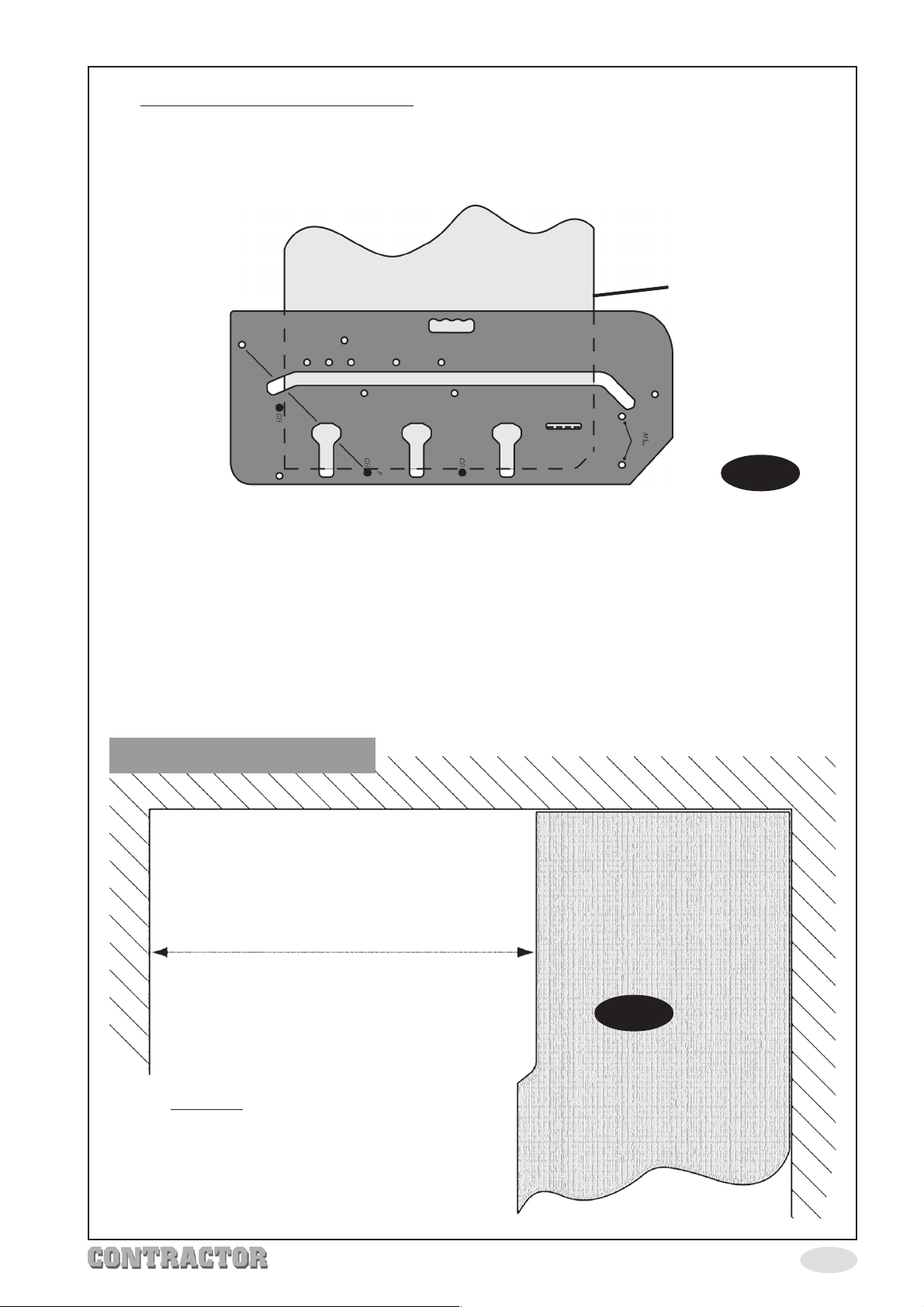
1. Female joint (Fig. 8) - prepare the worktop with the laminate face down and
the post form edge towards you.
‘F’
2. Fully insert 2 pins in the holes marked
3. Fully insert third pin in hole corresponding to the worktop width (e.g.700mm).
.
4. Ensure the 2 pins in holes
third pin in the worktop width hole is pushed firmly against the worktop edge.
Post Form Edge
‘F’
are pushed firmly against the post form edge, and the
Female joint - laminate face down.
Fig. 8
Cut Direction
5. Firmly clamp the jig onto the worktop ensuring the clamps do not obstruct the router
path.
6.
Cutting - follow steps 6 - 9 on page 6.
7.
Male Joint (Fig. 9) - Place the worktop with the laminate face up.
‘M’
8. Fully insert two pins in the jig holes marked
9. Refer to page 10, (cutting to length) to determine where to mark the pencil line for
positioning the jig on the worktop.
10. Ensure the two pins in holes
the jig lined up on the pencil line as above (Fig. 9 overleaf).
‘M’
are pushed firmly against the post form edge and
with angle symbol .
-8-
Page 10
11. Firmly clamp the jig to the worktop ensuring it doesn’t move as you do so. Ensure the
clamps do not obstruct the router path.
Cut Direction
Post Form Edge
Fig. 9
12.
Cutting - follow steps 6 - 9 on page 6.
Male Joint - Laminate face up.
Pencil Line
13.
Female Bolt Recesses (Fig. 10) - Place the worktop with the laminate face down.
14. Fully insert three pins in holes marked
15. Clamp the jig to the worktop ensuring the three pins are firmly pushed up to the cut
out face and the worktop edge. Ensure clamps do not obstruct the router path.
16. Place the router into the front of one of the clamp bolt recesses, set the depth of
cut to 10mm max. Switch the router ON and machine the recess. When done,
switch the router OFF and wait for the cutter to stop spinning. Return the router to
the back again. Increase the depth of cut a further 10mm and machine the recess
again. When finished, switch the router OFF and wait for it to stop spinning.
17. Repeat step 16 for the other 2 recesses (other 3 recesses for 900mm worktops).
‘CB’.
IMPORTANT
Recesses must be no deeper than 20mm maximum.
Female bolt recesses - Laminate face down.
Fig. 10
-9-
Post Form Edge
Page 11
18. Male Bolt Recesses (Fig. 11) - Place the worktop with laminate face down.
19. Fully insert 3 pins in the holes marked
20. Clamp the jig to the worktop ensuring all 3 pins are pushed firmly against the
worktop. Ensure clamps do not obstruct the router path.
Male bolt recesses Laminate face down.
‘CB’.
Post Form Edge
Fig. 11
21. Place the router into the front of one of the clamp bolt recesses, set the depth of
cut to 10mm max. Switch the router ON and machine the recess. When done,
switch the router OFF and wait for the cutter to stop spinning. Return the router to
the back again, increase the depth of cut a further 10mm and machine the recess
again. When finished, switch the router OFF and wait for it to stop spinning.
22. Repeat step 21 for the other 2 recesses (other 3 recesses for 900mm worktops).
IMPORTANT
Recesses must be no deeper than 20mm maximum.
Cutting To Length
1000mm
When producing a male joint left or right
hand, the position of the jig has to be
calculated. It is easier if the female joint is
cut first, leaving the gap intended for the
male part of the worktop.
Fig. 12
Example
The female joint has already been cut
(Fig. 12) the length of the male worktop
needed is 1000mm (1metre).
-10-
Page 12
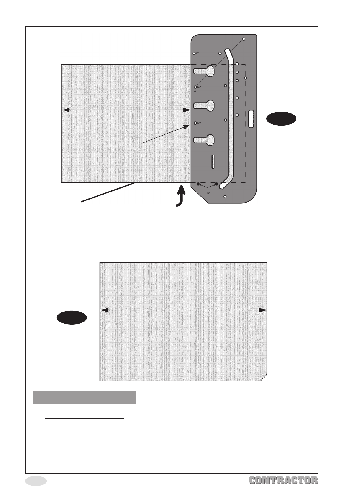
772mm
Pencil Line
Fig. 13
Post Form Edge
Position the jig onto the worktop to be cut into the male piece, referring back to the
instructions for cutting 90º joints. Subtract 228mm from the intended length,
e.g. 1000mm - 228mm = 772mm. Position the worktop jig 772mm from the opposite end
of the worktop you are cutting.
Cut Direction
1000mm
Fig. 14
Left Hand 45º Joints
1. Female joint (Fig. 15) - Refer to the diagrams on the different joints available.
Prepare the worktop with the laminate face up and the post form edge towards
the left.
2. Fully insert 2 pins in the holes marked
3. Position the jig as in Fig. 15 so that when the cut has been made, there is sufficient
length to enable trimming to length, see Fig. 16 over.
-11-
‘F’.
Page 13
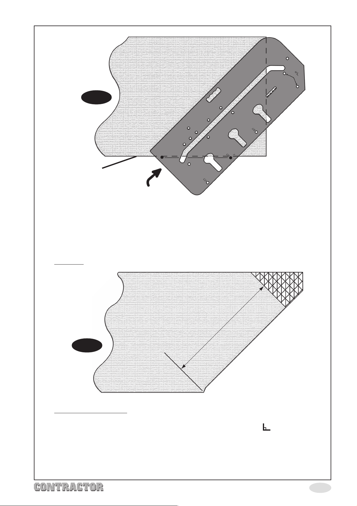
Fig. 15
Post Form Edge
Female joint - laminate face up.
Cut Direction
4. Ensure the 2 pins in holes
worktop, clamp the jig to the worktop ensuring clamps do not obstruct the router
path.
5. Once the cut is complete, remove the excess (Fig. 16 hatched area), using either
the router or a fine tooth saw.
Cutting - Follow steps 6 - 9 on page 6.
6.
‘F’
are pushed firmly against the post form edge of the
700mm
Fig. 16
7. Male Joint (Fig. 17) - Place the worktop with the laminate face down, taking
care to protect the surface.
‘M’
8. Fully insert two pins in the jig holes marked
9. Refer to page 10, (cutting to length) to determine where to mark the pencil line for
positioning the jig on the worktop.
10. Ensure the 2 pins in holes marked
and the jig on the pencil line (Fig. 17).
‘M’
are pushed firmly against the post form edge
with angle symbol .
-12-
Page 14
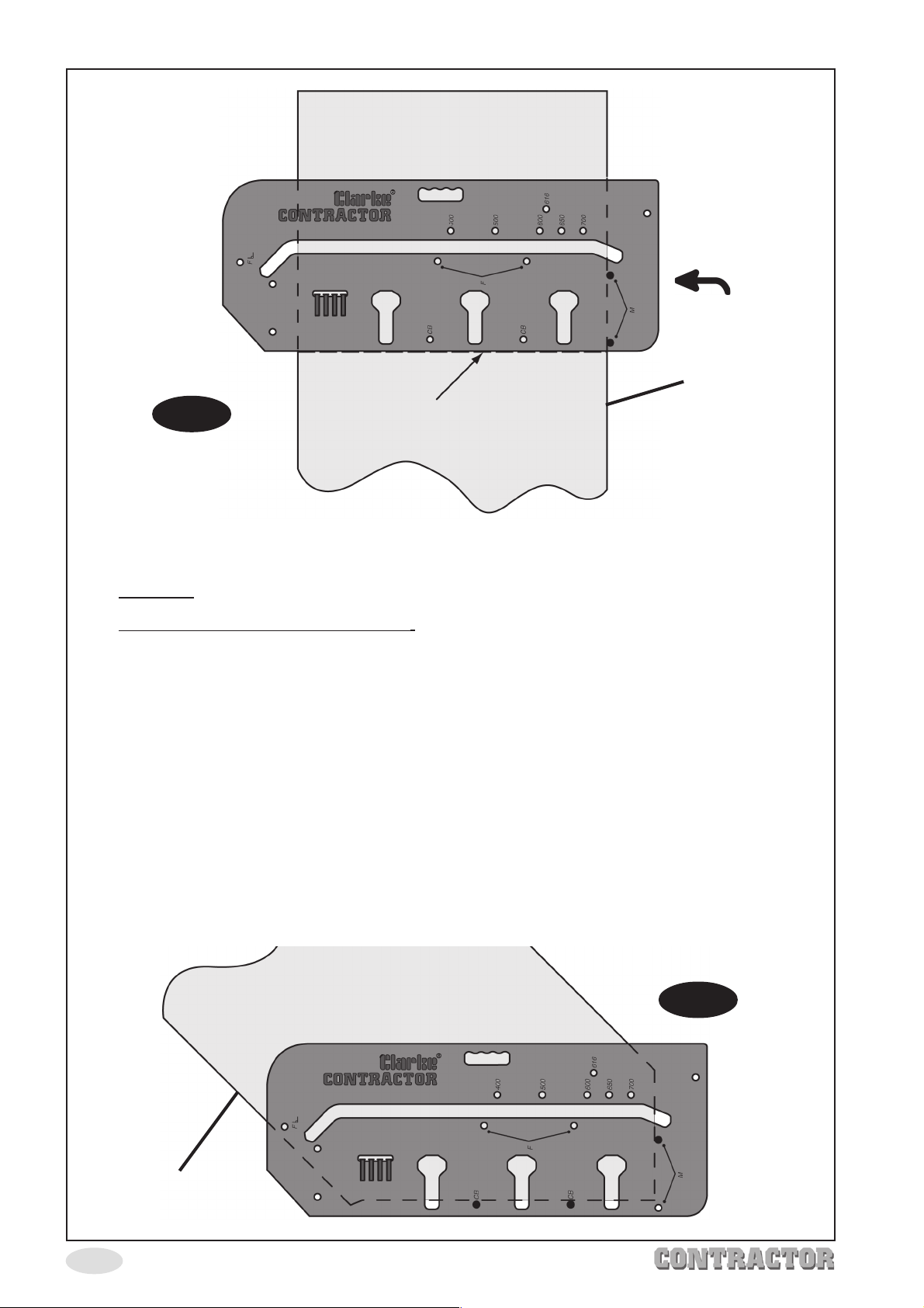
Cut Direction
Post Form Edge
Fig. 17
Male Joint - Laminate face down.
11. Firmly clamp the jig to the worktop ensuring it doesn’t move as you do so. Ensure the
clamps do not obstruct the router path.
Cutting - Follow steps 6 - 9 on page 6.
12.
13.
Female Bolt Recesses (Fig. 18) - Place the worktop with the laminate face down.
14. Fully insert three pins in holes marked
15. Clamp the jig to the worktop ensuring the three pins are firmly pushed up to the cut
out face and the worktop edge. Ensure clamps do not obstruct the router path.
16. Place the router into the front of one of the clamp bolt recesses, set the depth of
cut to 10mm max. Switch the router ON and machine the recess. When done,
switch the router OFF and wait for the cutter to stop spinning. Return the router to
the back again. Increase the depth of cut a further 10mm and machine the recess
again. When finished, switch the router OFF and wait for it to stop spinning.
17. Repeat step 16 for the other 2 recesses (other 3 recesses for 900mm worktops).
Pencil Line
‘CB’.
Post Form Edge
-13-
IMPORTANT
Recesses must be no deeper than 20mm maximum.
Female bolt recesses - Laminate face down.
Fig. 18
Page 15
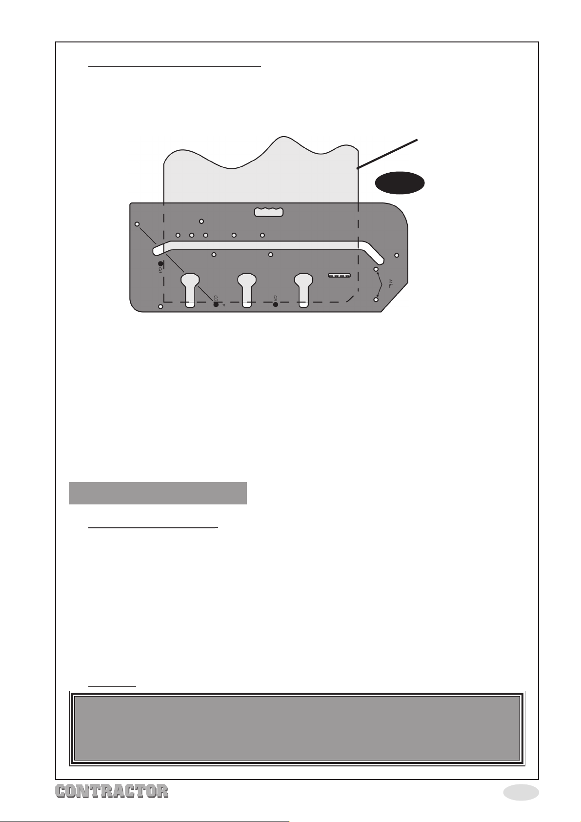
18. Male Bolt Recesses (Fig. 19) - Place the worktop with laminate face down.
19. Fully insert 3 pins in the holes marked
20. Clamp the jig to the worktop ensuring all 3 pins are pushed firmly against the
worktop. Ensure clamps do not obstruct the router path.
Male bolt recesses Laminate face down.
21. Place the router into the front of one of the clamp bolt recesses, set the depth of
cut to 10mm max. Switch the router ON and machine the recess. When done,
switch the router OFF and wait for the cutter to stop spinning. Return the router to
the back again. Increase the depth of cut a further 10mm and machine the recess
again. When finished, switch the router OFF and wait for it to stop spinning.
‘CB’.
Post Form Edge
Fig. 19
22. Repeat step 21 for the other 2 recesses (other 3 recesses for 900mm worktops).
IMPORTANT
Recesses must be no deeper than 20mm maximum.
Right Hand 45º Joints
1. Female joint (Fig. 20) - Refer to the diagrams on the different joints available.
Prepare the worktop with the laminate face down and the post form edge towards
the left.
2. Fully insert 2 pins in the holes marked
3. Position the jig as in Fig. 15 so that when the cut has been made, there is sufficient
length to enable trimming to length, see Fig. 16 page 12.
4. Ensure the 2 pins in holes
worktop, clamp the jig to the worktop ensuring clamps do not obstruct the router
path.
5. Once the cut is complete, cut off the excess, see Fig. 16.
Cutting - Follow steps 6 - 9 on page 6.
6.
‘F’
are pushed firmly against the post form edge of the
‘F’.
CAUTION
To Prevent damage to the laminate surface, take
extra care when working with laminate face down.
-14-
Page 16
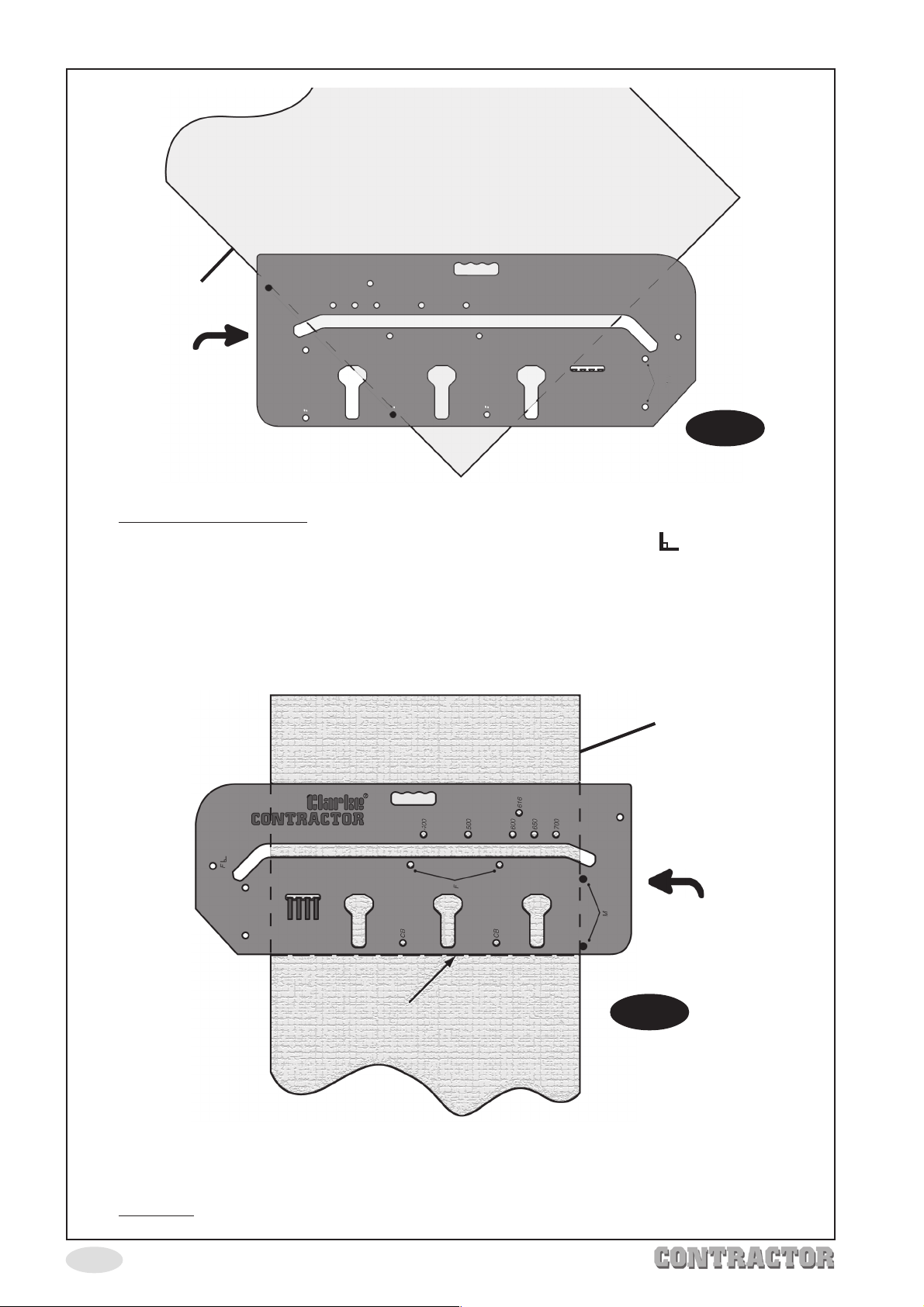
Female joint - laminate face down.
Post Form Edge
Cut Direction
Fig. 20
Male Joint (Fig. 21) - Place the worktop with the laminate face up.
7.
‘M’
8. Fully insert two pins in the jig holes marked
9. Refer to page 10, (cutting to length) to determine where to mark the pencil line for
positioning the jig on the worktop.
with angle symbol .
10. Ensure the 2 pins in holes marked
and the jig on the pencil line (Fig. 17).
Pencil Line
Male Joint - Laminate face up.
‘M’
are pushed firmly against the post form edge
Post Form Edge
Cut Direction
Fig. 21
11. Firmly clamp the jig to the worktop ensuring it doesn’t move as you do so. Ensure the
clamps do not obstruct the router path.
12.
Cutting - Follow steps 6 - 9 on page 6.
-15-
Page 17
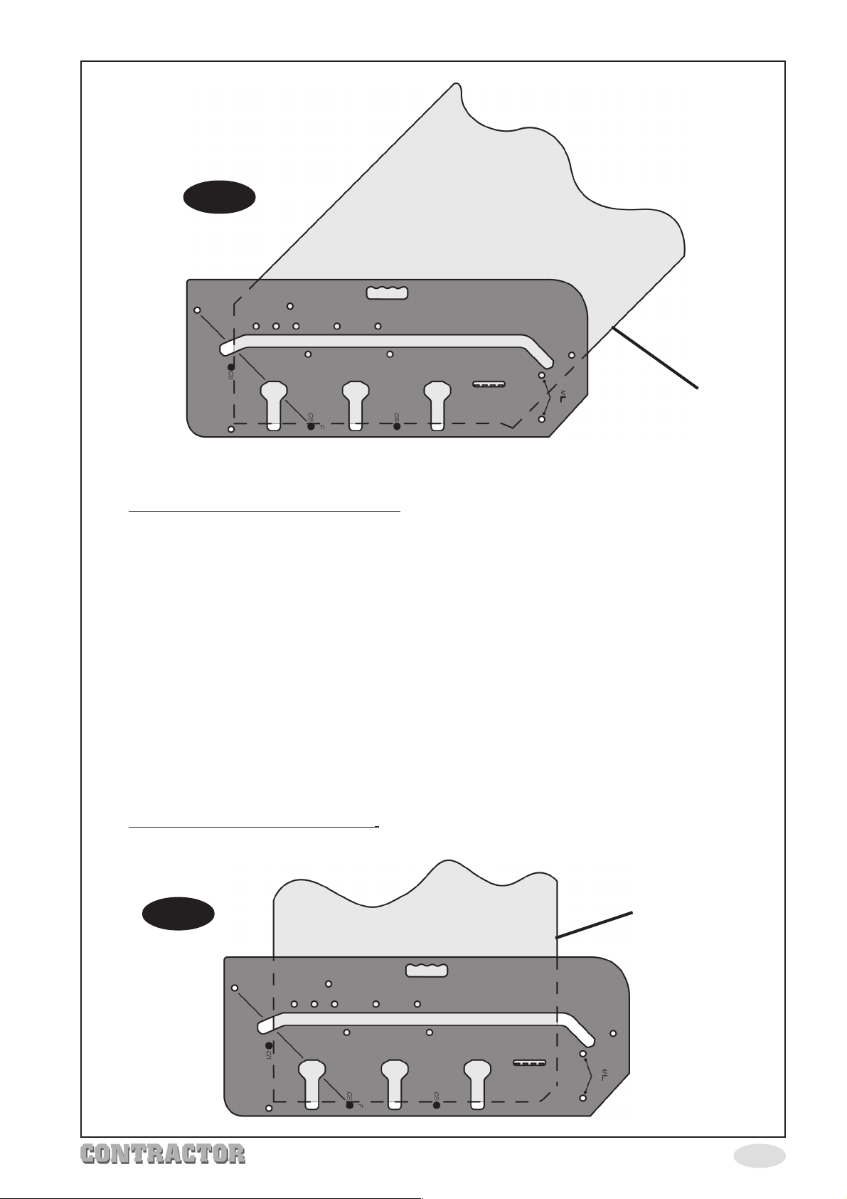
Fig. 22
Female bolt recesses - Laminate face down.
Post Form Edge
13. Female Bolt Recesses (Fig. 18) - Place the worktop with the laminate face down.
14. Fully insert three pins in holes marked
15. Clamp the jig to the worktop ensuring the three pins are firmly pushed up to the cut
out face and the worktop edge. Ensure clamps do not obstruct the router path.
16. Place the router into the front of one of the clamp bolt recesses, set the depth of
cut to 10mm max. Switch the router ON and machine the recess. When done,
switch the router OFF and wait for the cutter to stop spinning. Return the router to
the back again. Increase the depth of cut a further 10mm and machine the recess
again. When finished, switch the router OFF and wait for it to stop spinning.
17. Repeat step 16 for the other 2 recesses (other 3 recesses for 900mm worktops).
‘CB’.
IMPORTANT
Recesses must be no deeper than 20mm maximum.
18. Male Bolt Recesses (Fig. 23) - Place the worktop with laminate face down.
Fig. 23
Male bolt recesses Laminate face down.
Post Form Edge
-16-
Page 18
19. Fully insert 3 pins in the holes marked
20. Clamp the jig to the worktop ensuring all 3 pins are pushed firmly against the
worktop. Ensure clamps do not obstruct the router path.
21. Place the router into the front of one of the clamp bolt recesses, set the depth of
cut to 10mm max. Switch the router ON and machine the recess. When done,
switch the router OFF and wait for the cutter to stop spinning. Return the router to
the back again. Increase the depth of cut a further 10mm and machine the recess
again. When finished, switch the router OFF and wait for it to stop spinning.
22. Repeat step 21 for the other 2 recesses (other 3 recesses for 900mm worktops).
‘CB’.
IMPORTANT
Recesses must be no deeper than 20mm maximum.
1. Shaping Corners - Position jig on worktop as in Fig. 24 below.
2.
Cutting - Position the router (guide bush) on the edge of the jig at the post form end,
ensure the router base is flush on the jig surface. Set the cut depth to 10mm max.
3. Switch the router ON and slowly move the router following the edge of the jig.
Switch OFF and wait for the cutter to stop spinning.
4. Lift the router off the jig and return it to the start position again, increase the depth
of cut a further 10mm and make a second pass. Keep repeating steps 3 & 4 until
the cut is complete, i.e. the cutter is below the bottom of the worktop.
9. Switch the router OFF and wait for it to stop spinning, remove the router and jig,
store them away safely for reuse.
15mm
Post Form Edge
Cut Direction
15mm
-17-
Fig. 24
Page 19
Maintaining your worktop jig.
Your worktop jig requires no maintenance other than occasionally wiping it over with a
clean dampened soft cloth.
For ingrained dirt, a mild household cleaning agent can be used, DO NOT use any
solvents or chemicals as these can damage the jig.
Polishing with a propriety anti-static household polish, can aid the movement of the
router across the surface of the jig.
In case of loss, replacement pegs are available from your Clarke dealer.
Part No: WTJIG-01-PEGS-BK
HEALTH AND SAFETY
Always seek the assistance of an able bodied person when
lifting and manoeuvring heavy objects such as worktops
etc.
It is very important for one person to take charge, giving
very precise instructions of when and where to lift, plus how
heavy etc. the object being lifted is.
Failure to carry out this instruction could lead to serious
personal injury.
-18-
Page 20

 Loading...