

Page 1
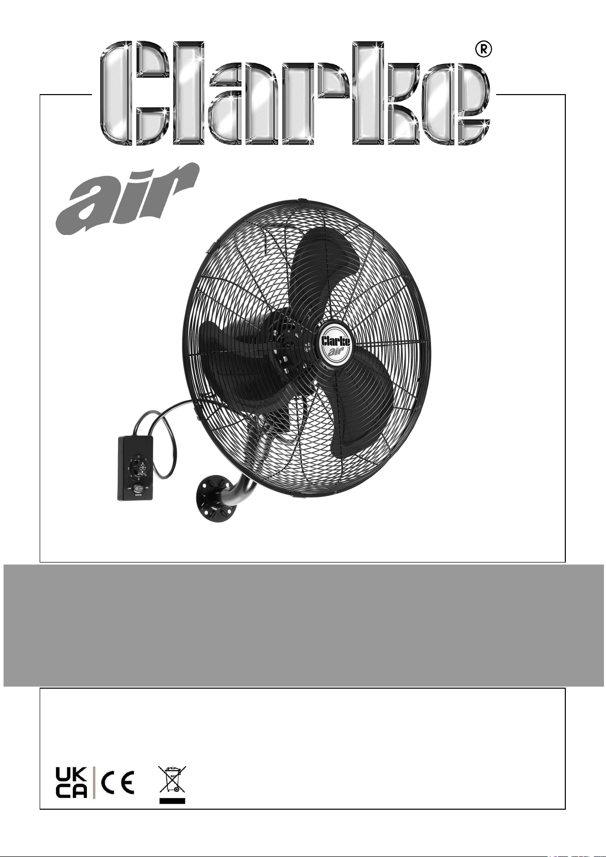
18” OSCILLATING WALL FAN
MODEL NO: CWFO18
PART NO: 3231546
OPERATION & MAINTENANCE
INSTRUCTIONS
ORIGINAL INSTRUCTIONS DL0125
Page 2
INTRODUCTION
Thank you for purchasing this CLARKE Wall Fan.
Before attempting to use this product, please read this manual thoroughly and follow
the instructions carefully. In doing so you will ensure the safety of yourself and that of
others around you, and you can look forward to your purchase giving you long and
satisfactory service.
ENVIRONMENTAL RECYCLING POLICY
By purchasing this product, the customer is taking on the obligation to deal
with its safe disposal in accordance with the Waste Electrical and Electronic
Equipment (WEEE).
In effect, this means that this product must not be disposed of with general
household waste. It must be disposed of according to the laws governing Waste
Electrical and Electronic Equipment (WEEE) at a recognised disposal facility.
If disposing of this product or any damaged components, do not dispose of with
general waste. This product contains valuable raw materials. Metal products should
be taken to your local civic amenity site for recycling of metal products.
GUARANTEE
This CLARKE product is guaranteed against faulty manufacture for a period of 12
months from the date of purchase. Please keep your receipt as proof of purchase.
This guarantee is invalid if the product is found to have been abused or tampered
with in any way, or not used for the purpose for which it was intended.
Faulty goods should be returned to their place of purchase, no product can be
returned to us without prior permission.
This guarantee does not effect your statutory rights.
2
Parts & Service: 020 8988 7400 / E-mail: [email protected] or [email protected]
Page 3
SAFETY PRECAUTIONS
1. ALWAYS read this manual before use.
2. DO NOT use outdoors. Suitable for indoor use only
3. DO NOT use in environments containing chemical fumes etc.
4. DO NOT use as an extractor fan or connect to a duct system.
5. DO NOT cover the fan with clothing or any material that will restrict free airflow
through the fan.
6. NEVER touch the blades with your hand or any object.
7. ALWAYS unplug the fan before performing maintenance. Don’t touch the fan
when your hands are wet.
8. DO NOT attempt to disassemble, repair or rebuild the fan.
9. NEVER use the fan if the cable or plug are damaged.
10. NEVER use the fan close to fires.
11. DO NOT use this fan with any solid-state speed control device to reduce the risk
of fire or electric shock.
12. AVOID using in dusty environments.
13. Use of extreme caution is necessary when the fan is used by or near children,
disabled persons or pets and whenever the fan is left operating unattended.
14. This appliance is not intended for use by persons (including children) with reduced
physical, sensory or mental capabilities or lack of experience and knowledge,
unless they have been given supervision or instruction concerning use of the
appliance by a person responsible for their safety.
15. Children should be supervised to ensure they DO NOT play with the appliance.
3
Parts & Service: 020 8988 7400 / E-mail: [email protected] or [email protected]
Page 4
ELECTRICAL CONNECTIONS
WARNING! READ THESE ELECTRICAL SAFETY INSTRUCTIONS
THOROUGHLY BEFORE CONNECTING THE PRODUCT TO THE
MAINS SUPPLY.
This product may be fitted with a non-rewireable plug. If it is necessary to change the
fuse in the plug, the fuse cover must be refitted. If the fuse cover becomes lost or
damaged, the plug must not be used until a suitable replacement is obtained.
If the plug has to be changed because it is not suitable for your socket, or due to
damage, it should be cut off and a replacement fitted, following the wiring
instructions shown below. The old plug must be disposed of safely, as insertion into a
mains socket could cause an electrical hazard.
WARNING! THE WIRES IN THE POWER CABLE OF THIS
PRODUCT ARE COLOURED AS FOLLOWS:
Blue = Neutral Brown = Live Yellow and Green = Earth
If the colours of the wires in the power cable of this product do not correspond with
the markings on the terminals of your plug, proceed as follows.
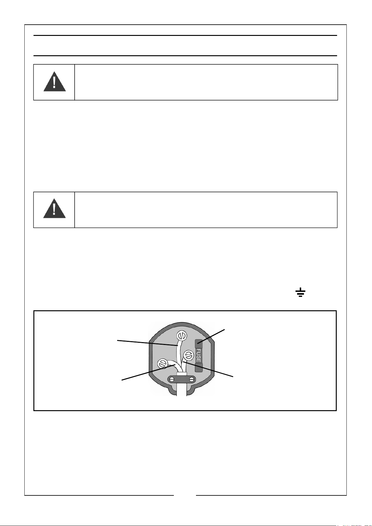
• Connect the Blue wire to the terminal marked N.
• Connect the Brown wire to the terminal marked L.
• Connect the Yellow and Green wire to the terminal marked E or
Plug must be BS1363/A approved.
Always fit a 3 Amp fuse.
Earth
(Green and Yellow)
Neutral
(Blue)
Ensure that the outer sheath of the cable is firmly held by the clamp
Live
(Brown)
We strongly recommend that this machine is connected to the mains supply via a
Residual Current Device (RCD)
If in any doubt, consult a qualified electrician. DO NOT attempt any repairs yourself.
4
Parts & Service: 020 8988 7400 / E-mail: [email protected] or [email protected]
Page 5
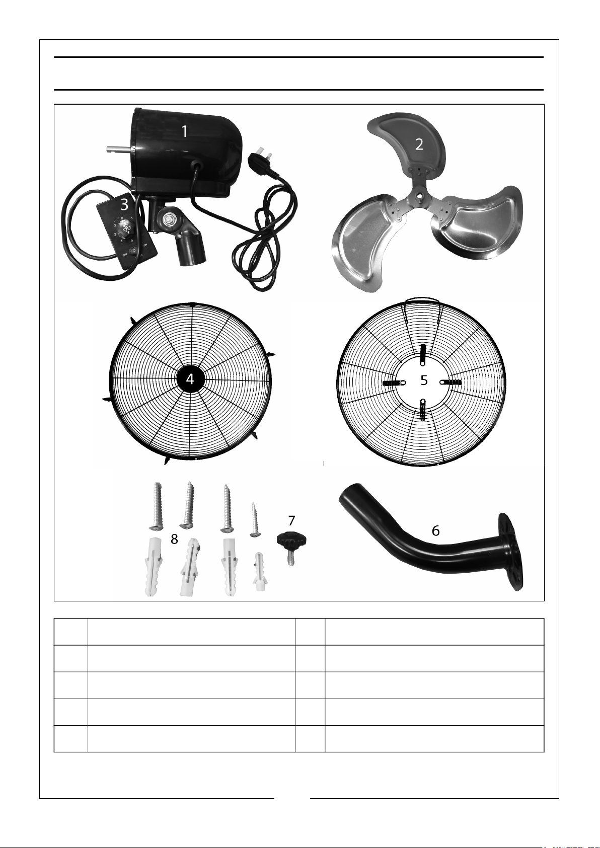
OVERVIEW - COMPONENTS
NO DESCRIPTION NO DESCRIPTION
1 Motor Housing 5 Rear Grill
2 Fan Blade 6 Hanging Wall Bracket
3 Control Box 7 Positioning Screw
4 Front Grill 8 Wall Bracket Fixings x 4
5
Parts & Service: 020 8988 7400 / E-mail: [email protected] or [email protected]
Page 6
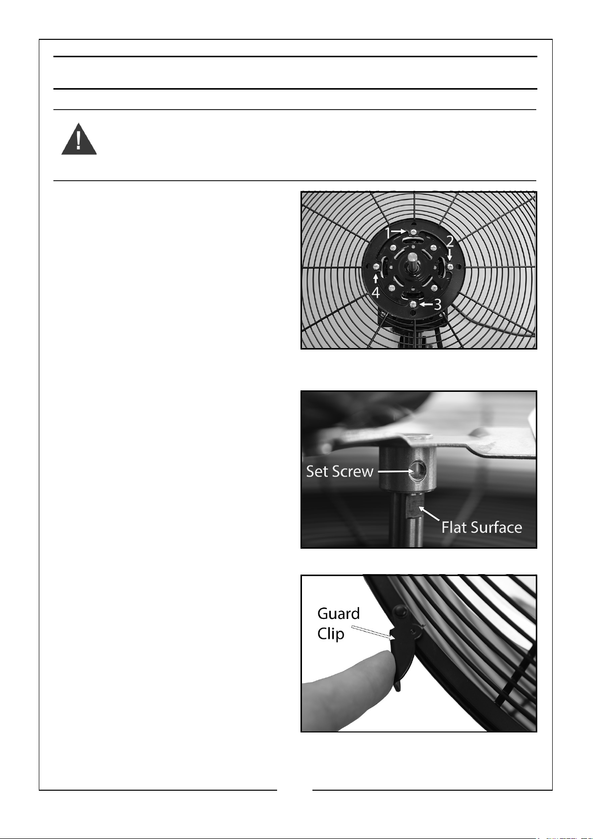
INSTALLATION
CAUTION: USE THE FOLLOWING INFORMATION AS A GUIDELINE ONLY. IT
IS THE USER’S RESPONSIBILITY TO BE SURE THE LOCATION AND THE WALL
SURFACE CAN HANDLE THE WEIGHT OF THIS FAN.
1. Remove the four mounting screws
from the motor housing (as shown).
2. Mount the rear guard onto the motor
housing using these four screws.
3. Tighten the four screws securely.
• Keep the security screw hole in the
rear guard at the bottom and the
handle at the top.
4. Place the fan blade onto the motor
shaft, as shown.
5. Tighten the blade set screw securely
on the flat surface on the motor
shaft.
6. Attach the front guard to the rear
guard using the hook clip centered on
the top wire handle.
7. Press the remaining guard clips onto
the rear guard to securely attach the
front guard.
6
Parts & Service: 020 8988 7400 / E-mail: [email protected] or [email protected]
Page 7
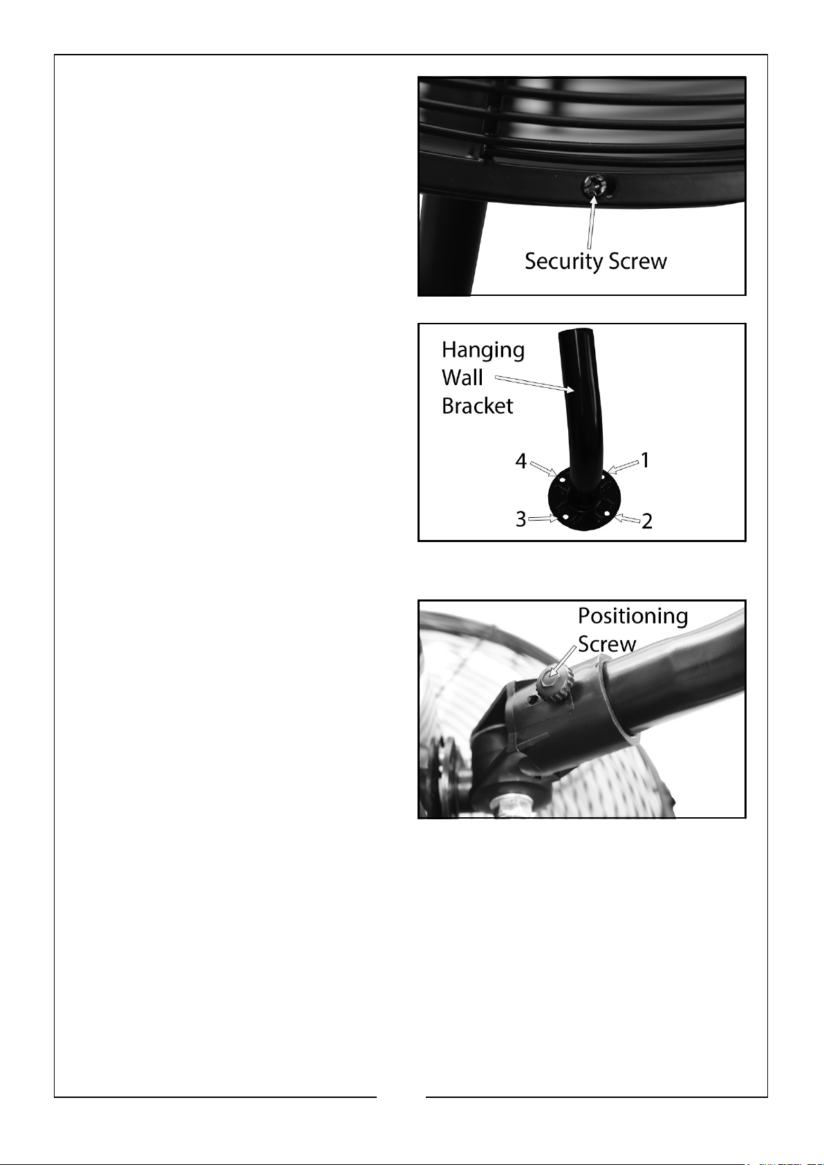
8. Use the security screw and nut to
tighten the fan grill in position.
NOTE: DO NOT operate the fan
without the guard being in
place.
9. Confirm the wall fan height as
needed, then mark the position of
the hanging wall bracket will be
located using the four screw holes, as
shown.
10. Drill four holes in the wall.
NOTE: Hole dimensions should be a
minimum of 5/16” diameter
and 1 3/4” depth.
11. Insert the four wall plugs into the
holes and screw the bracket tightly to the wall.
12. Insert the supporting bracket of the
fan on to the pole, align the holes
and tighten them with the positioning
screw in one of the two holes.
13. If you require to install the control box on the wall, confirm the position as
needed.
14. Drill one hole in the wall, insert the wall plug and screw and tighten until the head
of the screw is approximately 2-3mm from the wall.
7
Parts & Service: 020 8988 7400 / E-mail: [email protected] or [email protected]
Page 8
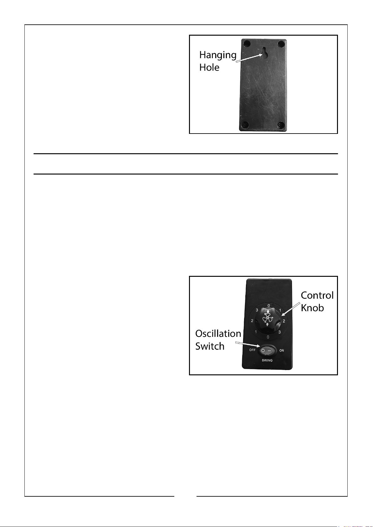
15. Hang the control box on a screw
using the hanging hole in the back of
the box.
NOTE: To prevent damage to the
control box cord and motor, the
distance between the control
box and the wall bracket should
be no more than 50cm.
OPERATING
1. Plug the fan directly into a 230V 50Hz wall outlet. Be sure the plug fits tightly in
the outlet. A loose connection may cause overheating and damage to the plug or
fan.
NOTE: To prevent overloading a circuit, DO NOT plug the fan into a circuit
that is servicing other electrical needs. It is normal for the motor to feel
warm to the touch after continuous operation. This fan features a
thermostat that will automatically shut off of it overheats for any
reason. If this happens, unplug the fan from the outlet immediately.
2. Control the fan oscillation by pressing
the rocker switch ‘SWING’ on the
control box, OFF or ON.
3. To operate the fan, turn the control
knob on the control box through the
following positions.
• Position 0 - Off
• Position 1 - Slow
• Position 2 - Medium
• Position 3 - Fast
8
Parts & Service: 020 8988 7400 / E-mail: [email protected] or [email protected]
Page 9
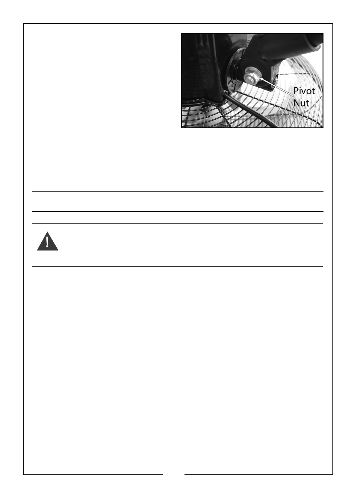
4. To adjust the airflow upwards or
downwards, loosen the pivot nut on
the rear of the fan, adjust the fan to
the desired angle and firmly tighten
the pivot nut.
CUT OUT SAFETY DEVICE
This fan has a thermal cut out safety device built in. If it activates, turn off the power
and let the fan cool for 5 minutes. Once cooled, turn the power back on and resume
operation. If the problem persists, contact your local CLARKE service centre.
MAINTENANCE
WARNING: NEVER OPERATE THE FAN WITH THE FRONT GRILL
REMOVED. ALWAYS DISCONNECT THE POWER CABLE FROM THE
POWER SUPPLY BEFORE PERFORMING MAINTENANCE WORK
Have any repairs carried out by a suitably qualified person.
• The motor and bearings are permanently sealed for life and do not require
any additional lubrication.
CLEANING
If the fan has been operating for long periods the blades and motor assembly may
eventually require cleaning.
1. Release the clips retaining the front guard and lift it away carefully.
2. Wipe the fan blades with dry cloth and remove any dust from the motor assembly
with a soft brush, vacuum cleaner or jet of compressed air.
• Always wear a dust mask and glasses when using compressed air.
3. Never use any cleaning product or any corrosive liquid that will damage the
surface finish.
4. Replace the guard securely before use.
9
Parts & Service: 020 8988 7400 / E-mail: [email protected] or [email protected]
Page 10
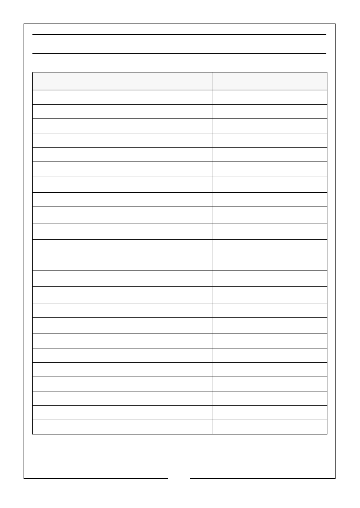
SPECIFICATIONS
MODEL CWFO18
Operating Voltage and Frequency 230 V AC (50Hz)
Rated Input Wattage 100 W
Rated Input Ampage 0.43 A
Electrical Insulation Class Class I
Duty Cycle Classification S1 - Continuous
Ingress Protection (IP) Rating IP20
Operating Temperature Range
Safety Device Thermal Cut Out Safety Device
Safety Device Temperature Cut Out
Swivel Range
Revolving Range
Maximum Fan Speed 1300 rpm
Maximum Air Flow
Max Fan Air Flow Rate
Fan Power Input 96.9 W
Service Value
Standby Power Consumption 0 W
Fan Sound Power 72 dB
0 to 35oC
135oC
o
30
85o Between Left & Right
70.3 m3/min
61.6 m3/min
0.6 m3/min/W
Maximum Air Velocity 3.6 m/s
Seasonal Electricity Consumption 31 kWh/a
Dimensions (W x D x H) 510 x430 x 550 mm
Fan Diameter 457 mm / 18 inch
Weight 5.5 kg
10
Parts & Service: 020 8988 7400 / E-mail: [email protected] or [email protected]
Page 11
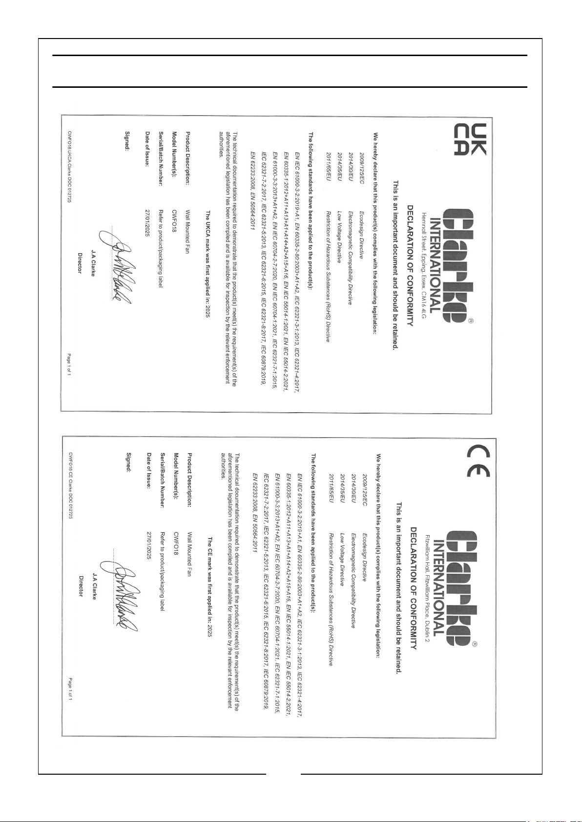
DECLARATION OF CONFORMITY
11
Parts & Service: 020 8988 7400 / E-mail: [email protected] or [email protected]
Page 12

 Loading...