

Page 1
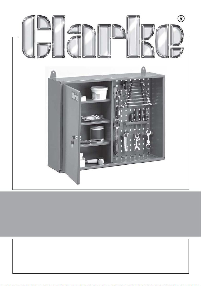
Wall Storage Rack & Cabinet
Model: CWC80B
Part No: 4800265
ASSEMBLY INSTRUCTIONS
GC07/12
Page 2
PRE-ASSEMBLY CHECK
Unpack the components and lay them out carefully. Referring to the parts list
ensuring that all parts are present. If there are any deficiencies, immediately
contact the dealer from where the product was purchased, or the Clarke
International Parts Department on 020 8988 7400.
ASSEMBLY
NOTES: When assembling, all screw heads should be on the outside of the
cabinet. DO NOT tighten any nuts until the cabinet is fully assembled.
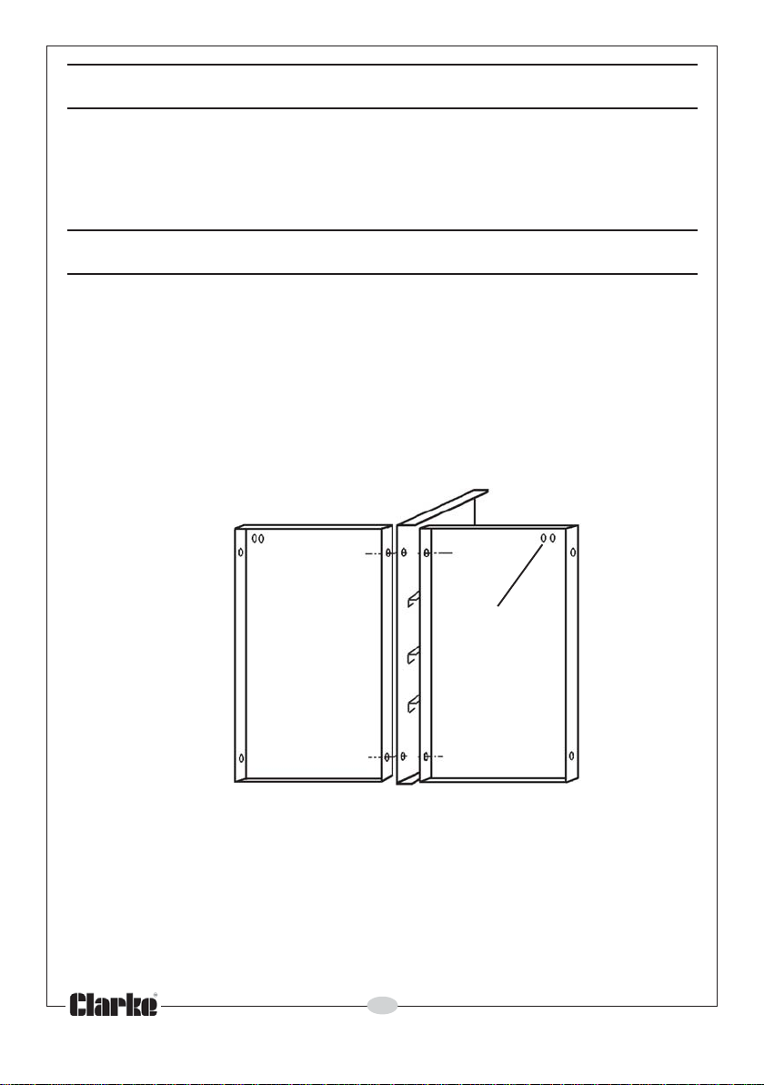
Make a note of the position of the wall mounting holes in each back
panel. These must be uppermost when the cabinet is assembled.
1. Take the back panels as shown in Fig 1, with the central side panel (with
shelf brackets) positioned between them as shown.
NOTE: The central side panel includes brackets to support the shelves and
must therefore face the end panel with the corresponding shelf brackets.
FIG 1
Mounting Holes
2. Line up the holes and connect with a screw & nut at each location.
3. Place the top panel on to the back panel assembly as shown in Fig 2, so
that the edge with the return fold lies at the front and connect all parts
loosely together.
4. Offer up the other side panel with shelf brackets to one end so that the
shelf brackets match those at the centre of the unit. Line up the corner
holes at ‘A’, and secure with a screw/nut.
5. Repeat at the front corners. Repeat the process with the other side panel.
2
Parts & Service: 020 8988 7400/E-mail:[email protected] or [email protected]
Page 3
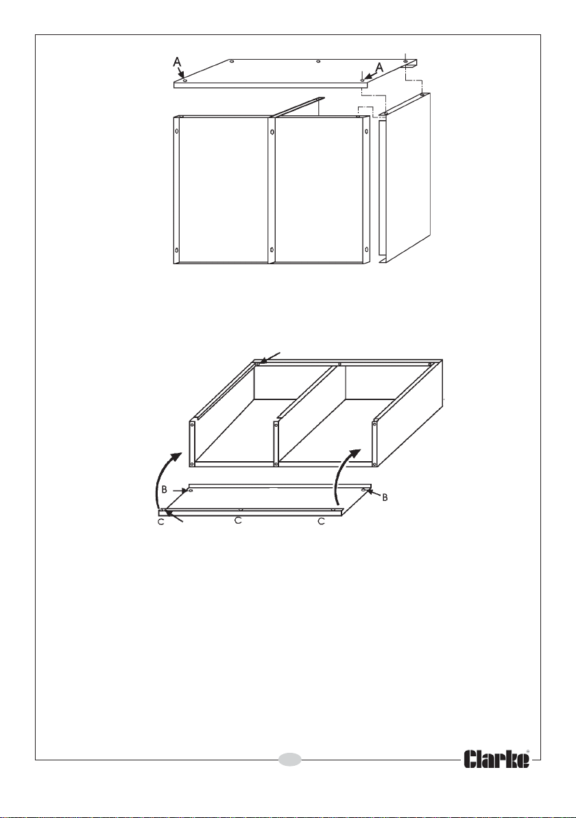
FIG 2
6. Lay the assembly down, as shown in Fig 3 and offer up the bottom panel
(the edge with the return fold uppermost).
7. Line up the holes in each corner at B and loosely insert a screw & nut.
FIG 3
Pivot Hole
Pivot Hole
8. Attach the door by inserting the pivot pins into the pivot holes in the top
and bottom panels. Line up the holes at C, insert a screw and with the
door open, fit a nut at each corner.
9. With the cabinet lying on a flat surface, as in Fig 3, rock it gently to ensure
that no part is unduly stressed, before tightening all the screws/nuts
progressively.
10. Attach the wall hanging brackets to the back panels using the screws and
nuts provided.
Your wall cabinet is now ready to hang. Ensure it is firmly attached to the wall
before loading with tools. Wall plugs and screws are provided for the purpose.
The shelves are rested on the supporting brackets, while the tool holders
engage with the back panel, and may be positioned to your own choice.
3
Parts & Service: 020 8988 7400/E-mail:[email protected] or [email protected]
Page 4
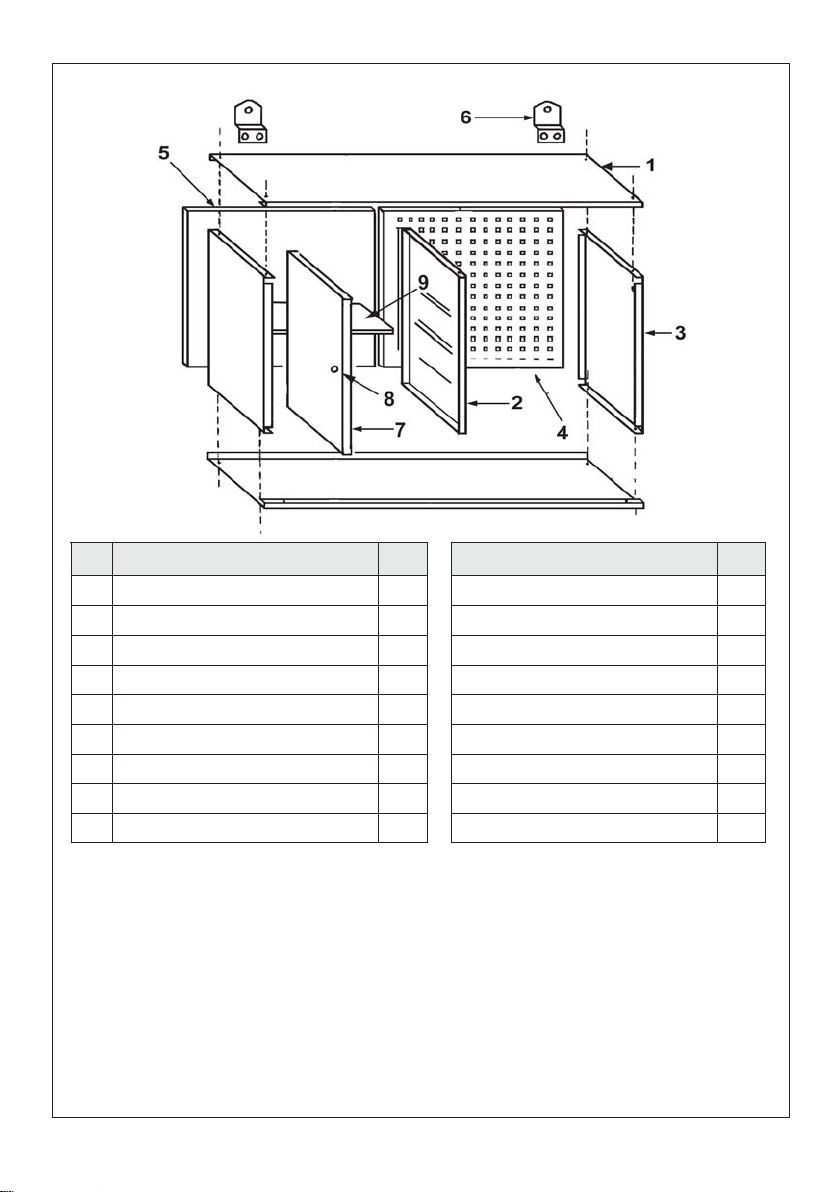
PART LIST & DIAGRAM
oN noitpircseD ytQ noitpircseD ytQ
1lenaPmottoB/poT2gulPllaW2
2stekcarbflehshtiwlenaPediS2wercSgnitnuoM2
3lenaPediSnialP101x5MwercS81
4lenaPkcaBdetarofr
eP15MtuN81
5lenaPkcaBnialP1sredloHlooTelgniS5
6stekcarBgnignaHllaW2redloHhcnerW1
7rooDtnorF1redloHrevirdwercS1
8yekhtiwys
9flehS3
sAkcoLrooD1redloHeliF1
GUARANTEE
This CLARKE product is guaranteed against faulty manufacture for a period of
12 months from the date of purchase. Please keep your receipt as proof of
purchase. This guarantee is invalid if the product is found to have been
abused or tampered with in any way, or not used for its intended purpose.
Faulty goods should be returned to their place of purchase, no product can
be returned to us without prior permission. This guarantee does not effect
your statutory rights.
 Loading...