

Page 1
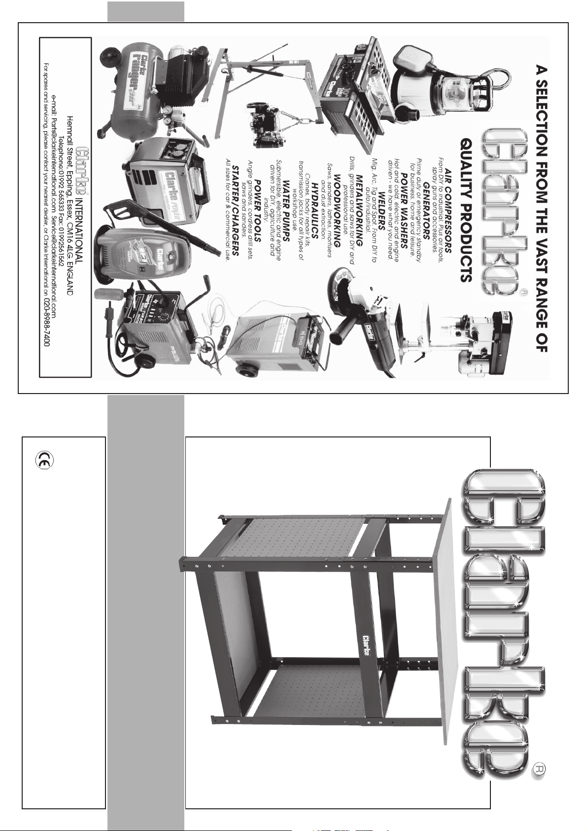
Work Bench/Tool Stand
Work Bench/Tool Stand
Assembly & User Instructions
Model No: CWB2
Part No: 7637710
1205
Page 2
Please note that the details and specifications contained herein, are correct at the time of going to print. However,
Leg (F): ......................................... HTCWB2005 ................ 4 off
Side Panel (C): ............................ HTCWB2006 ................ 2 off
Shelf (B): .......................................HTCWB2007 ................ 1 off
Long Beam (D): ........................... HTCWB2009 ................ 4 off
Short Beam (E): ...........................HTCWB2010 ................ 4 off
Floor Guard (J): ...........................HTCWB2011 ................ 4off
Leg Extension (G): .......................HTCWB2013 ................ 4off
Bench Top (A): ............................ HTCWB2016 ................ 1off
Hardware Bag (nuts & bolts etc)(I): ............................... HTCWB2020 1 off
CLARKE International reserve the right to change specifications at any time without prior notice.
-1-
Spares
Maximum load on bench top: ................. 50kg
Depth: .......................................................... 410mm
Work Top Area: ............................................ 690 x 510mm
Height (variable):........................................ 620mm to 830mm in 42mm increments
width: ........................................................... 610mm
Model No: .................................................... CWB2
Part No: ........................................................ 7637710
intended.
Faulty goods should be returned to their place of purchase, no product
can be returned to us without prior permission.
This guarantee does not effect your statutory rights.
Specifications
Thank you for purchasing this CLARKE workbench/toolstand
Before attempting to use this equipment, please read this manual thoroughly and follow
the instructions carefully. In doing so you will ensure the safety of yourself and that of others
around you, and you can look forward to the bench giving you long and satisfactory service.
This CLARKE product is guaranteed against faulty manufacture for a period
of 12 months from the date of purchase. Please keep your receipt as proof
of purchase.
This guarantee is invalid if the product is found to have been abused or
tampered with in any way, or not used for the purpose for which it was
CLARKE GUARANTEE
-6-
(d) Turn the completed bench back onto it’s
NOT overtighten.
feet site on a firm flat surface, the bench
should be firm and stable without rocking
etc, any instability should be rectified
before attempting to attach any
equipment.
SERVICE: [email protected]
PARTS: [email protected]
PARTS & SERVICE TEL: 020 8988 7400
or e-mail as follows:
(c) Turn the assembled frame upside down
and lay on bench top (Fig. 8), line up the
pilot holes with the elongated ones and
secure in position with screws supplied, DO
(c) Carefully drill out pilot holes using suitable sized drill
pre-marked pilot holes facing upwards.
for the securing screws supplied, take care not to
drill completely through to top.
6. Fit floor guard (‘J’) to the bottom of each leg, tap in place with a soft faced hammer/
8. When completely satisfied the unit is as square as
possible, the top can be fitted as follows.
(a) Loosely fit one angle bracket (‘H’) top of each
NOTE: when fitting angle bracket to the leg, ensure it
is fitted on the inside of the leg with the elongated
hole at the top (Fig. 7).
(b) lay the bench top on a flat level surface with the
leg using nuts and bolts supplied.
Elongated Hole
7. Stand the completed assembly on a flat level surface and tighten all securing screws,
mallet, alternatively a block of wood or similar.
ensuring the unit is square etc. Once all securing nuts and bolts are fully tightened,
recheck the assembly for squareness, if not square, rectify before continuing.
Fig. 8
Fig. 7
Page 3
-5- -2-
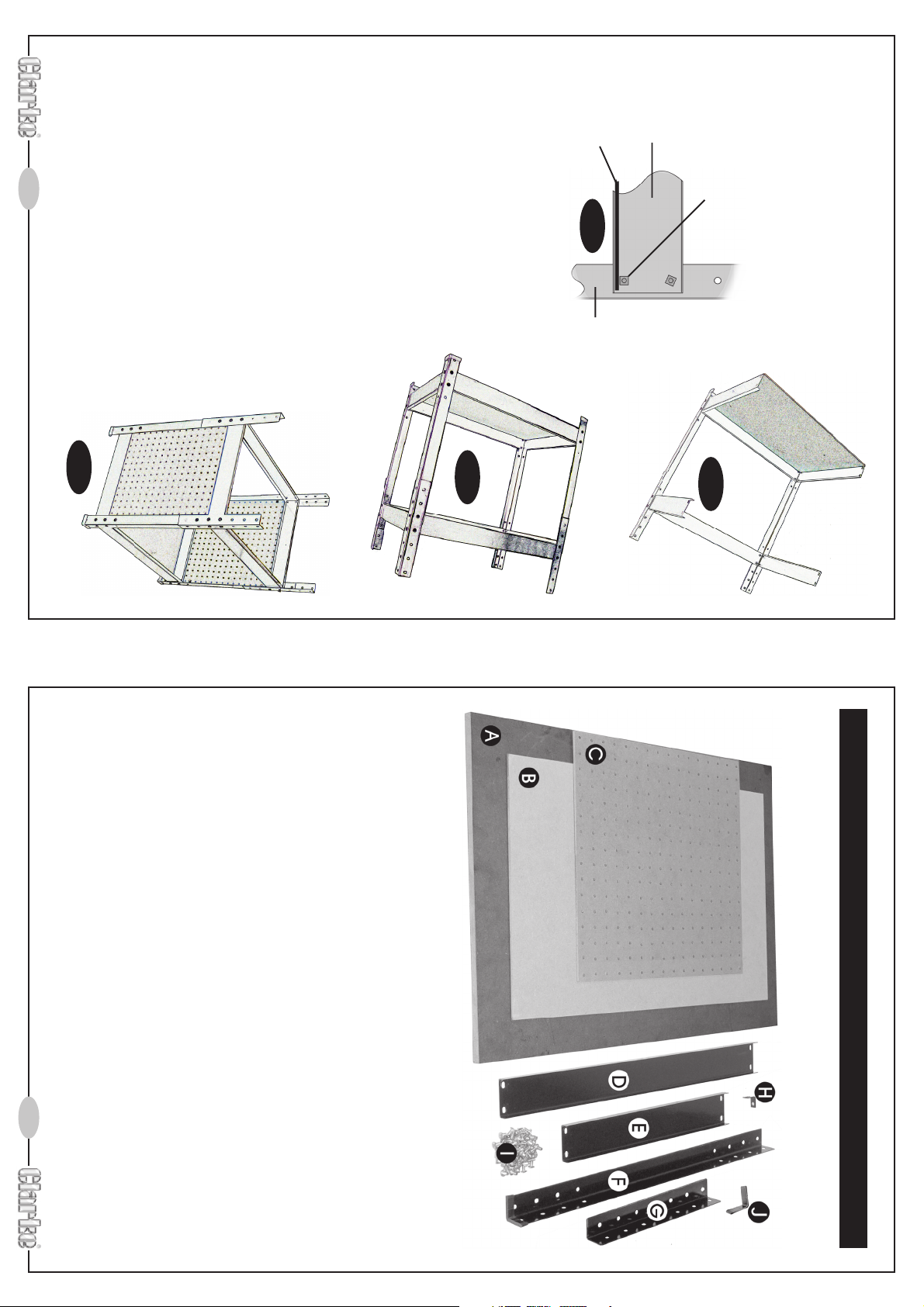
5. Fit side panel (‘C’) inside the frame between the legs
and short beams, secure with nuts and bolts supplied.
Repeat for other side panel.
4. Fit the second leg assembly as in Fig. 5,
again ensuring the beam flanges are all the
same and the shelf is between the flanges
and nuts (Fig. 4a).
Shelf
Fig. 4a
Leg
Lower Beam
nuts so that the flats on the nuts are parallel to
the shelf ledge in order to obtain this (Fig. 4a).
Securing Nuts
4. Slide the bottom shelf (‘B’) into the assembly
as shown in Fig. 4, the shelf should sit on the
lower flanges and between the flanges and
securing nuts, it may be necessary to rotate the
Fig. 6
The workbench MUST only be used on a firm, flat level surface as there are no levelling feet
etc to compensate for uneven surfaces.
NOTE: the height of the bench is determined by the position of the leg extensions, determine
the required height before fitting the extensions.
The height can be adjusted from as low as 620mm up to a maximum of 830mm in increments
of 42mm.
Fig. 5
NOTE: The workbench can be used to support a wide range of power tools etc, however it
is very important to ensure that any equipment is attached to the bench top and firmly
secured by either drilling fixing holes and bolting to the top using suitable nuts and bolts etc,
alternatively suitable clamps can be used, i.e. ‘G’ clamps.
As well as securing the machine to the bench, careful consideration must be given to the
bench height, any equipment used on this bench must not cause the bench to become
unstable, i.e. if the height or weight of the machine causes the assembly to become top
heavy and unstable, DO NOT USE, if in doubt contact your Clarke dealer for advice.
‘A’ Bench Worktop x 1off. ‘B’ Bottom Shelf x 1off.
‘C’ End Panel x 2 off. ‘D’ Long Beam x 4 off.
‘E’ Short Beam x 4 off. ‘F’ Leg x 4 off.
‘G’ Leg Extension x 4 off. ‘H’ Angle Bracket x 4 off.
‘I’ Nuts and bolts etc. ‘J’ Floor Guard (Foot) x 4 off.
Fig. 4
Before attempting to assemble your workbench, check for any shortages and/or dam-
age, any discrepancies should be reported to your Clarke dealer as soon a s possible.
Contents
Page 4
-3- -4-
11. ALWAYS ensure the switch is off before plugging in to mains. Avoid
13. ALWAYS keep your proper footing and balance at all
times - don’t overreach. For best footing, wear rubber
soled footwear. Keep floor clear of oil, scrap wood,
etc.
12. ALWAYS concentrate on the job in hand, no matter
accidental starting.
how trivial it may seem. Be aware that accidents are
caused by carelessness due to familiarity.
10. ALWAYS handle with extreme care do not carry the tool/machine
clean for the best and safest performance. Follow maintenance
instructions.
by its’ electric cable, or yank the cable to disconnect it from the
power supply.
8. A LWAYS keep children away. All visitors should be kept a
9. A LWAYS maintain machine in top condition. Keep tools/machines
safe distance from the work area, especially whilst operating the machine.
4. ALWAYS disconnect the tool/machine from the power supply before servicing and
5. ALWAYS wear safety goggles, manufactured to the latest European Safety Standards.
6. A LWAYS keep work area clean. Cluttered areas and
7. A LWAYS ensure that adequate lighting is available. A
properly, and perform its intended function. Check for alignment
of moving parts, breakage of parts, mountings, and any other
condition that may affect the machines operation. Any damage should be properly
repaired or the part replaced. If in doubt, DO NOT use the machine. Consult your
local dealer.
when changing accessories.
Everyday eyeglasses do not have impact resistant lenses, they are not safety glasses.
benches invite accidents.
minimum intensity of 300 lux should be provided. Ensure
that lighting is placed so that you will not be working in
your own shadow.
2. A LWAYS use a face or dust mask if operation is particularly dusty.
3. A LWAYS check for damage. Before using the machine, any
damaged part, should be checked to ensure that it will operate
with the entire operating manual.
1. A LWAYS Learn the machines applications, limitations and the
ignored, personal injury to the operator or damage to property, may result.
specific potential hazards peculiar to it. Read and become familiar
As with all machinery, there are certain hazards involved with their operation
and use. Exercising respect and caution will considerably lessen the risk of
personal injury. However, if normal safety precautions are overlooked or
Safety Precautions
WARNING:
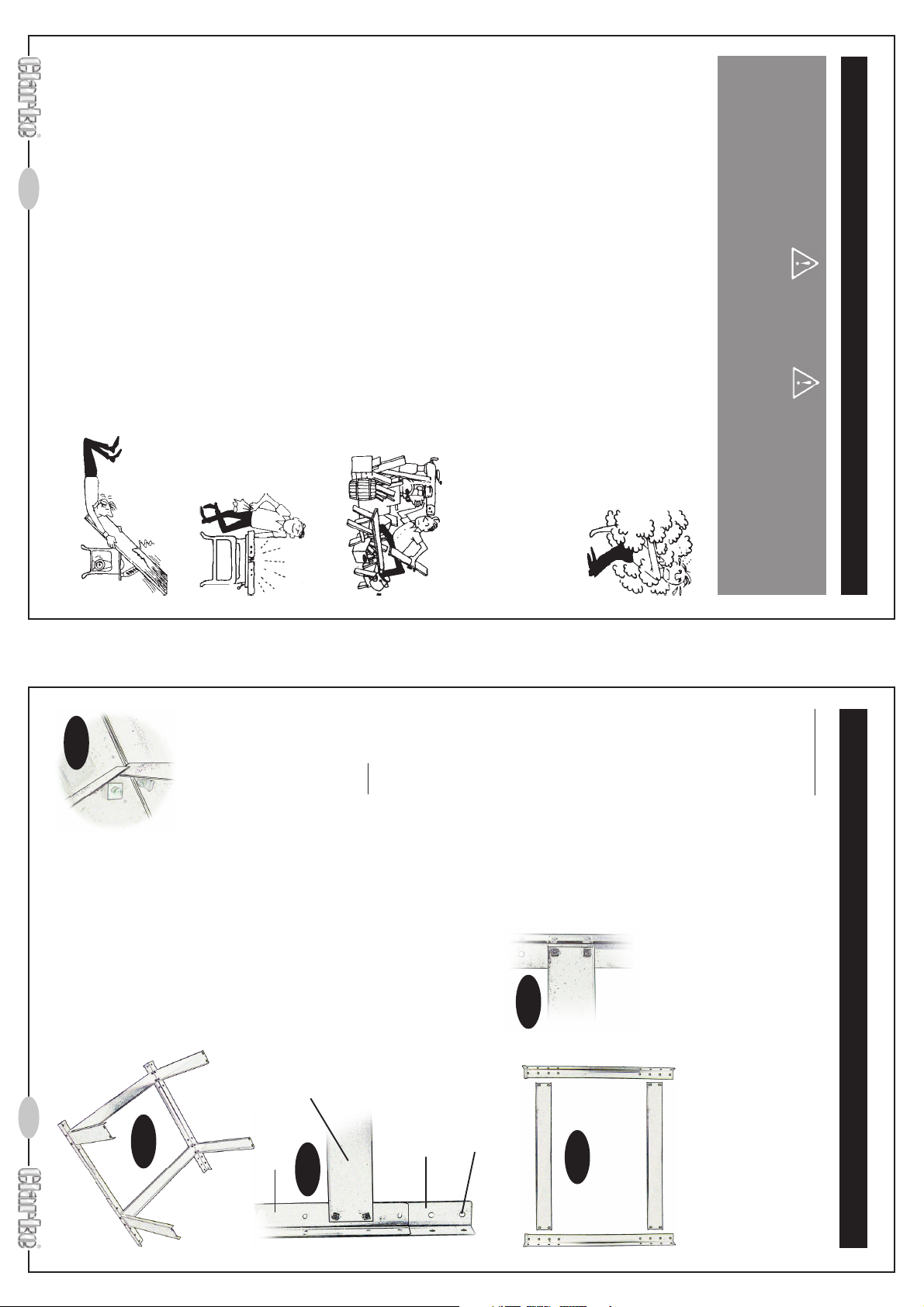
Fig. 3a
NOTE: when fitting the shorter
beams, they can be fitted with
the flanges either on top or
below the flanges of the longer
beams, we recommend
whatever you choose, they are
all fitted the same (Fig. 3a).
Fig. 3
4. Loosely attach the four shorter beams to one of
the assemblies, again fitting to the middle two
holes, top and bottom.
NOTE: the leg extensions are fitted to the outside of the
legs and MUST be secured with minimum of two screws,
if making up the lowest configuration (620mm), there is
no need to fit the leg extensions, if this option is chosen,
store the leg extensions safely in case the top needs
raising later.
3. Repeat steps 1 & 2 above for the remaining legs,
beams and leg extensions.
Upper Long Beam
Leg
Fig. 2
see. 2.
2. Loosely attach the upper long beams to both legs
IMPORTANT: hole nearest to the end of leg extension, MUST be at the top.
to the inside of both legs using
nuts and bolts supplied, nuts
as above, this time include the leg extensions (‘G’),
Fig. 1a
Leg extension
on the inside (Fig. 1a).
Fig. 1
1. Lay out 2 legs (‘F’) and 2 long beams (‘D’) in position
using the middle two holes, top and bottom.
as in Fig. 1.
attach the lower long beam
Note: the braces are fitted to the legs,
Loosely
Tools required:
Phillips screwdriver.
8mm combination spanner.
9mm open ended spanner.
Assemble the bench as follows:
Fit all nuts and bolts finger tight only until the bench is fully assembled.
NOTE: figures in brackets refer to contents on page 2.
Assembly
 Loading...